Comparative Energy Analysis of a Load Sensing System and a Zonal Hydraulics for a 9-Tonne Excavator


1
Department of Engineering and Architecture, University of Parma, 43124 Parma, Italy
2
Faculty of Engineering and Natural Sciences, IHA Innovative Hydraulics and Automation, Tampere University, FI-33720 Tampere, Finland
3
Department of Energy, Politecnico di Torino, C.so Duca degli Abruzzi 24, 10129 Turin, Italy
*
Author to whom correspondence should be addressed.
Actuators 2020, 9(2), 39; https://doi.org/10.3390/act9020039
Submission received: 14 April 2020
/
Revised: 18 May 2020
/
Accepted: 19 May 2020
/
Published: 20 May 2020
(This article belongs to the Special Issue Electro-Hydraulic Actuators)
Abstract
:With the rising demand for energy efficiency, displacement-controlled or so-called pump-controlled systems have become an attractive research topic for applications in construction machinery and other off-road vehicles. Pump-controlled systems can be implemented with electro-hydrostatic actuators as electro-hydraulic zones, which are located next to the end actuator as a replacement for the traditional valve-controlled hydraulic actuation systems. In this paper a 9-tonne class excavator is utilized as a study case. A mathematical model of the conventional machine, validated with tests carried out on both the excavator and the single hydraulic components, was previously developed within the Simcenter AMESim© environment. This mathematical model was modified with electric components for simulating a zonal hydraulics excavator and compared with a conventional load sensing (LS) machine. The energy efficiencies of both the LS circuit and the new solution were evaluated for typical duty cycles, pointing out the obtainable energy efficiency improvements, which were mainly due to the absence of the directional valves and pressure compensators. The results also point out the effect of the pipe losses when the circuit layout requires the pipe for connecting the pump with the actuator; moreover, the effect of a diesel engine downsizing on the energy saving was evaluated.
1. Introduction
The strengthening of air-quality regulations and combustion engine emission limits in off-road mobile machinery has pushed researchers to investigate new energy saving solutions and efficiency improvement in general. Various research groups have already conducted investigations of the hybridization of architectures in order to improve the efficiency of the entire powertrain system or drivetrain. In this well-established area of research, the authors in [1,2] demonstrate the ways to improve the efficiency of hydraulic systems by the application of novel system solutions and the adaption of energy recovery. The most widely adapted approach is the harvesting of potential and/or kinetic energy. The harvesting of potential energy from the lowering boom motion or kinetic energy from the turning of the swing drive are state-of-the-art examples for excavator application (for details refer to [3,4,5,6]). Overall, the proposed approaches can be divided based on the utilized form of energy storage: electric (battery, supercapacitor, etc.) or hydraulic. The balance between the price of the utilized components and the efficiency becomes a key selection factor for any vehicle or off-road mobile machinery applications [7]. Due to the costs of the components, many researchers have turned to exploring the combination and improvement of all the systems and subsystems of the machine.
Currently, interests in replacing traditional valve-controlled hydraulic actuation systems [8] with pump-controlled or displacement-controlled electro-hydrostatics is growing in many areas of applications such as aeronautics [9,10], ground [11], undersea vehicles [12], and robotics [13] applications. For instance, the concept of distributed or zonal hydraulics instead of centralized hydraulics is originated from the aeronautics with concept of a “more electric aircraft (MEA)” [9]. One of the realizations of zonal hydraulics can be implemented with electro-hydrostatic actuator (EHA) systems, which offer compactness and high efficiency, in addition to plug-and-play installations. Numerous references describe the advantages and disadvantages of EHA compared to valve-controlled conventional hydraulic systems. For instance, in [14] a hydraulic circuit utilizing two valves to compensate for the differential flow of asymmetrical actuators demonstrated superior improvement of efficiency when compared to a load-sensing (LS) circuit. The hydraulic power delivered by the pump in the proposed circuit was about 23% of the power required by a LS circuit.
In [15], the authors proposed six different self-contained drive architectures with self-locking features, which were directly controlled by pump. The power losses and energy recovery potentials were analyzed for the proposed architectures, and the results were compared with a conventional valve-controlled hydraulic drive architecture. Another electro-hydraulic self-contained asymmetrical cylinder drive with passive load-holding capability was proposed in [16]. Padovani et al. reported on a single-boom crane system implementation, in which the position tracking error remained within ±2 mm and which showed a total efficiency of about 60% during actuation motion.
An actuator directly driven by a linear pump was proposed in [17] for distributed actuation in an airplane. The proposed solution omits the needs of valves to balance flow in the asymmetrical cylinder.
Takahashi et al. in [18] proposed an EHA system for double-acting single rod cylinder system for landing gear. This concept has been adopted not only in the aerospace field, but several studies for implementation of EHA for ground vehicles have also recently been completed; for instance, in [19] the authors present a literature review including the concepts based on variable-displacement hydraulic pumps and variable-speed electric drives, and throughout comparison analysis of the advantages of each drive class. Authors in [19] spotted a trend towards the novel system architectures based on electrical prime movers stepping away from diesel engines. The ability of pump-controlled drives to harvest energy and to share power afterwards between multiple actuators adds a new role in future designs of hydraulically actuated multi-linked applications. According to [20], excavators as a complex multi-linked construction machinery, are contribution up to 60% of the CO2 emissions produced by construction machinery. Subsequently, the cut in greenhouse gases production by excavators can lead to a significant reduction in the world CO2 emission level. Work by Aalto university research group in [21,22] demonstrated that an EHA-type system enables up to 50% reduction in energy consumption compared to conventional low-cost Load Sensing valve-controlled system. This work was conducted with 1-tonne excavator test case.
The primary goal of this study is to demonstrate the advantage of zonal hydraulics on a 9-tonne excavator. More specifically, in this paper such an architecture will be compared to conventional LS hydraulics implemented on the same machine. The zonal hydraulics is realized with direct driven hydraulics (DDH).
The research activity presented in this paper is based on simulations carried out with an excavator mathematical model developed in an AMESim© environment. The excavator model is based on a lumped parameter approach that, in the hydraulic version, includes the following models: diesel engine, pump, directional flow control valves, hydraulic lines and kinematics of the front equipment. The standard LS excavator model was validated with experimental activities carried out on the excavator and on the single components, with the engine fuel consumption and many parameters measured during typical duty cycles. Other modelling approaches that can be found in literature [23,24,25,26,27] focus on more detailed aspects, while the followed approach permits the simulation of the components with computational run times suitable for circuit simulations [28]. The validated mathematical model of the standard hydraulic excavator [29,30,31,32,33,34,35,36,37] was modified and used for investigating new layout configurations based on zonal hydraulics.
The remainder of this paper is organized as follows. In Section 2, a standard/conventional hydraulic excavator mathematical model is presented. Section 3 describes the validation experimental activities with standard/conventional excavator. The results of a solution based on zonal hydraulics are described in Section 4. Section 5 presents the comparison results obtained with the standard LS and DDH model. The conclusion and final remarks are presented in Section 6.
2. Standard Hydraulic Excavator Mathematical Model
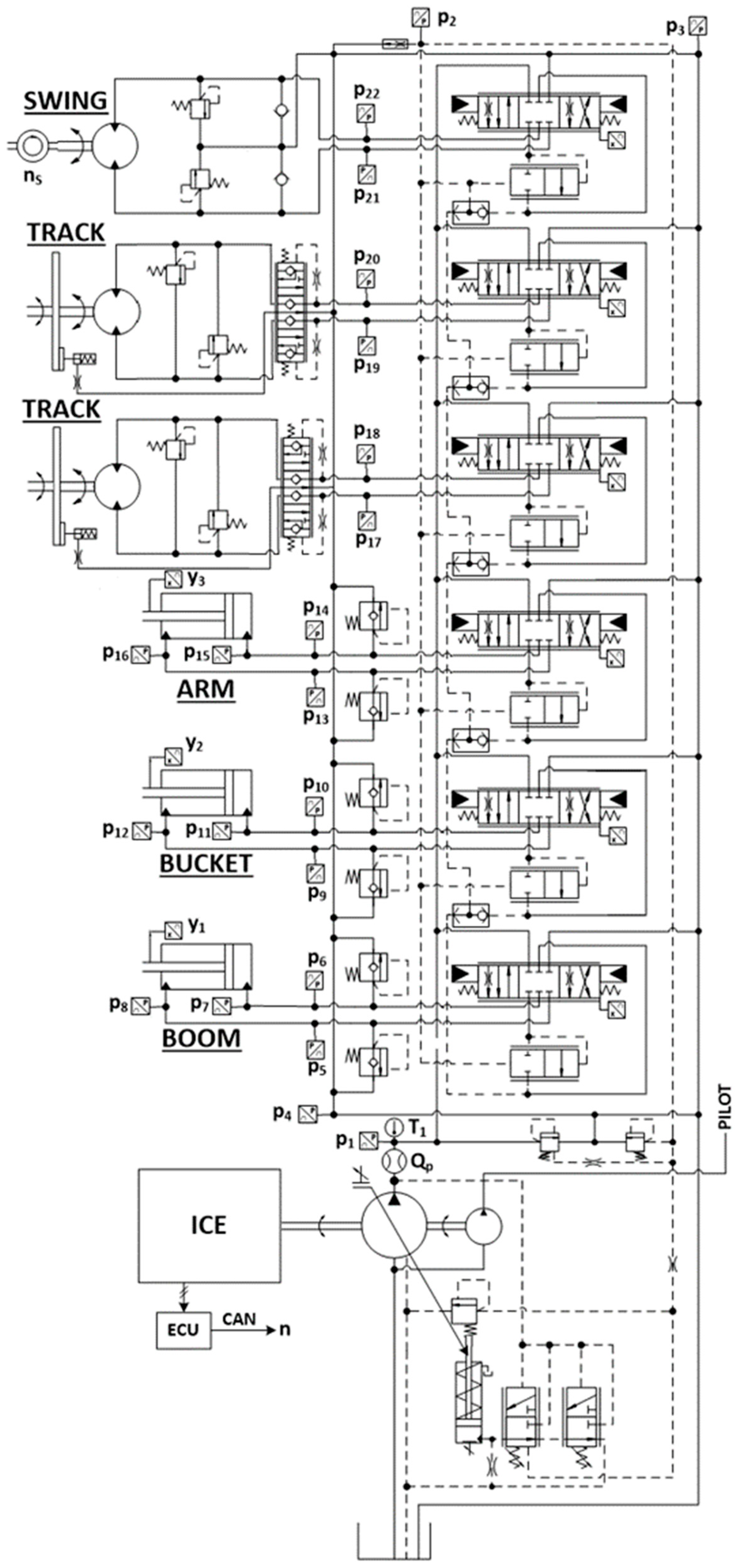
The 9-tonne hydraulic excavator in standard version is equipped with a 46 kW diesel engine (internal combustion engine (ICE)), the hydraulic circuit is a traditional Load sensing system, with a flow sharing directional valve and axial piston pumps. The attachment boom, arm, bucket and swing have been modelled. The ISO scheme of system layout of standard excavator, with the installed sensors for testing, is illustrated in Figure 1.
The mathematical model implemented is based on a lumped parameter approach and the main assumptions considered are listed below: constant tank pressure; fluid inertial effects in pipes are neglected; mechanical bodies are considered as rigid; mechanical joints have one degree of freedom; friction in revolute pairs are neglected. The mathematical model was developed using the AMESim® software; following a short description of the main features of the implemented sub-models is reported. For a detailed explanation refer to our earlier publication [34].
2.1. Pump Model
Two pumps are installed in the system. The pilot pump is an external gear unit that feeds the pilot hydraulic circuit, for this pump the simulations were carried out assuming the overall efficiency constant. The pump that feeds the main hydraulic circuit is an axial piston pump, the displacement is controlled by the pressure compensator (PC), the flow compensator (FC) and the torque limiter (TL). The pump is simulated with a gray box model composed by the combination of white box models for its regulators (PC, FC and TL) and a black box model of the pump flow characteristic. The model was already presented in detail and verified in [29,37], and the volumetric and hydro-mechanical efficiency maps were experimentally defined.
2.2. LS Flow Sharing Valve Block Model
The main valve of is a LS flow sharing valve block and its ISO scheme is represented in Figure 1. The valves permit control of the velocity of the movements, since each post-compensator maintains a constant pressure drop across the corresponding metering area, and the LS pressure is conveyed through the valve to the pump. Moreover, even when the main pump reaches the saturation condition, the same pressure drop is maintained in all sections (flow sharing).
The mathematical model is based on a lumped parameter approach, and it has been validated in [31,37] with the comparison between the simulation and experimental results obtained during laboratory tests carried at the University of Parma, Italy. The LS flow sharing valve block model has been developed in the AMESim © environment.
2.3. Hydraulic Cylinder Model
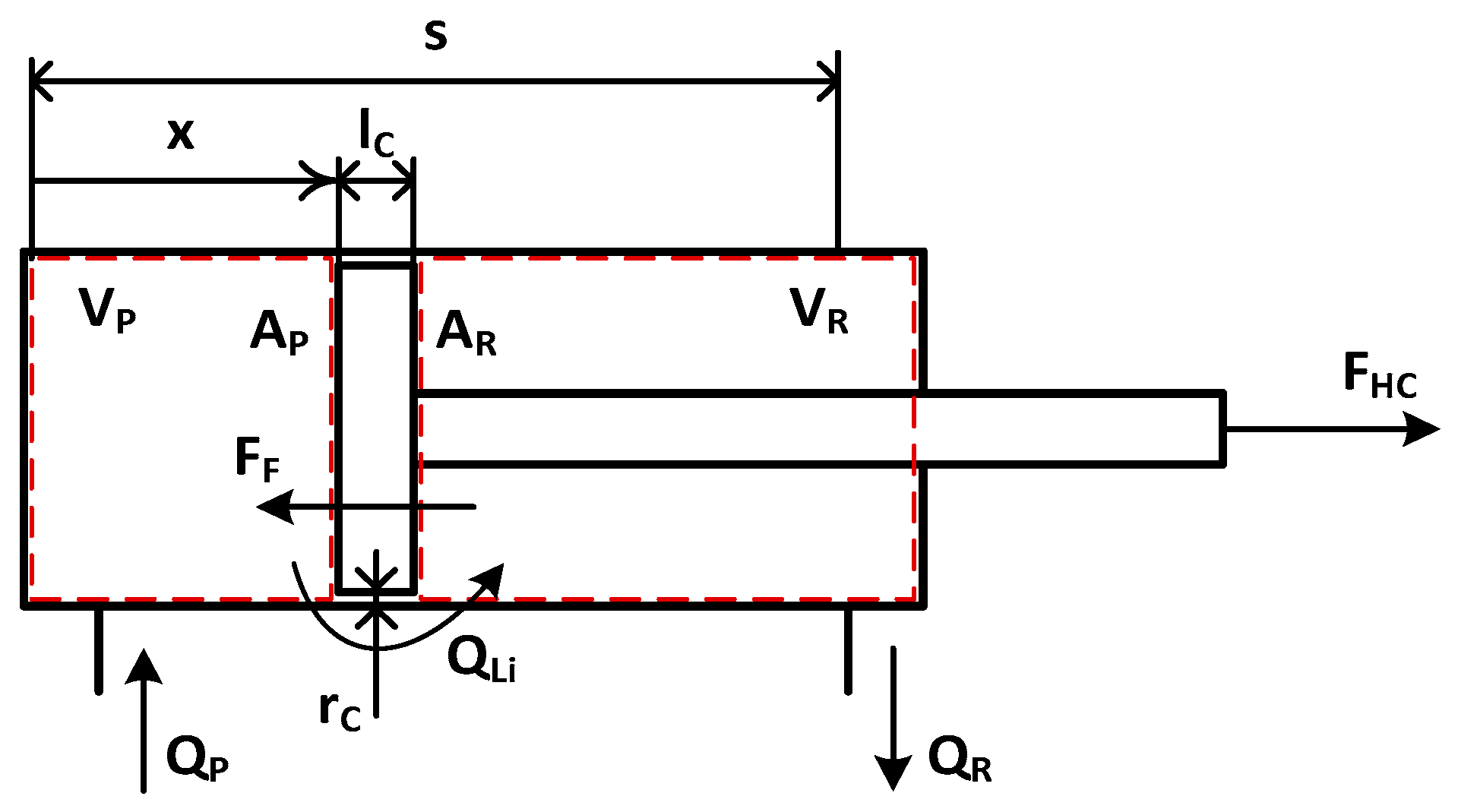
The hydraulic cylinders are double acting single-rod cylinders. The model is based on the scheme reported in Figure 2. The modelling approach considers the following assumptions: external cylinder leakages are neglected; the cylinder is considered rigid; to simplify the model the linear friction model includes the friction in in revolute pairs [37].
The hydraulic cylinders have been modelled defining two control volumes for the piston and rod side, respectively. Applying the continuity equation and fluid state equation, the pressures rise rates are reported in Equation (1) and Equation (2).
The leakages flow rate is defined by Equation (3):
The force exerted by the actuator, FHC, is calculated considering both the pressure and frictional forces, FF, in Equation (4). While the frictional force is defined by Equation (5), where the Coulomb friction force, FC, and the viscous friction coefficient, kV, were defined according to experimental results in [28]:
2.4. Turret Motor Model
The fixed displacement motor for rotating the turret is considered in the present study. The mathematical model is based on filling and emptying equations [34]. The computation of the real exerted torque hydro-mechanical efficiency is considered; when the hydraulic machine works as a pump, i.e,. during the turret decelerations, the hydro-mechanical efficiency is properly accounted [38]. The motors for the tracks have not been considered.
2.5. Hydraulic Pipe Losses Model
The pressure losses in the hydraulic pipes were computed considering the laminar flow based on the results obtained during the experimental tests. The tests were conducted measuring the fluid pressure at the beginning of the pipes (close to the directional valves) and at the end of the pipes (close to the linear actuators). The model computes the losses considering a simple pipe, for each line, with equivalent diameter that reproduces the measured losses. The average length of the pipes is 5 m for the boom, 7 m for the arm and 8 m for the bucket, while the pipe internal equivalent diameter is 10 mm for boom and arm, and 8 mm for the bucket. The pipe pressure losses were calculated according to Equation (6). The parameter kL was experimentally defined for each ith hydraulic line of interest.
2.6. Excavator Kinematic Model
The model of the front equipment and turret was developed to consider actual forces and torques on the respective hydraulic actuators [33,37]. This model remains the same for the DDH solutions presented in this paper.
2.6.1. Front Equipment
The front equipment model is made of the boom, arm and bucket, assumed as rigid bodies linked together by revolute pairs and linear actuators. The behavior of these bodies was completely defined by introducing the following parameters, defined with the aid of the 3D CAD model of the linkage: mass; center of gravity; moment of inertia of the body relative to an axis passing through the center of gravity; position of joints.
Using linear spring stiffness and damping coefficient, the forces () exchanged between two bodies in revolute joints are calculated with Equation (7) and Equation (8):
where (x1, y1) and (x2, y2) are the pivot joint coordinates relative to body 1 and 2. The masses of boom and arm incorporate the masses of the cylinder actuators. The centrifugal forces and the Coriolis forces acting on the bodies when the turret rotates have been neglected.
2.6.2. Turret
The turret has been modelled assuming a constant inertia, a constant position of the front equipment has been fixed, both Coulomb friction and viscous friction terms are considered. The dynamic equilibrium of the turret is defined by Equation (9):
Experimental tests have permitted to define the viscous and Coulomb coefficient, fast and slow rotation cycles were carried out.
2.7. Internal Combustion Engine Model
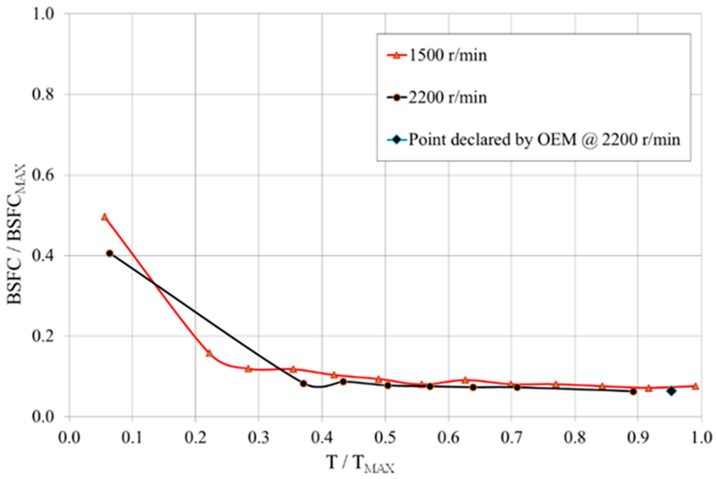
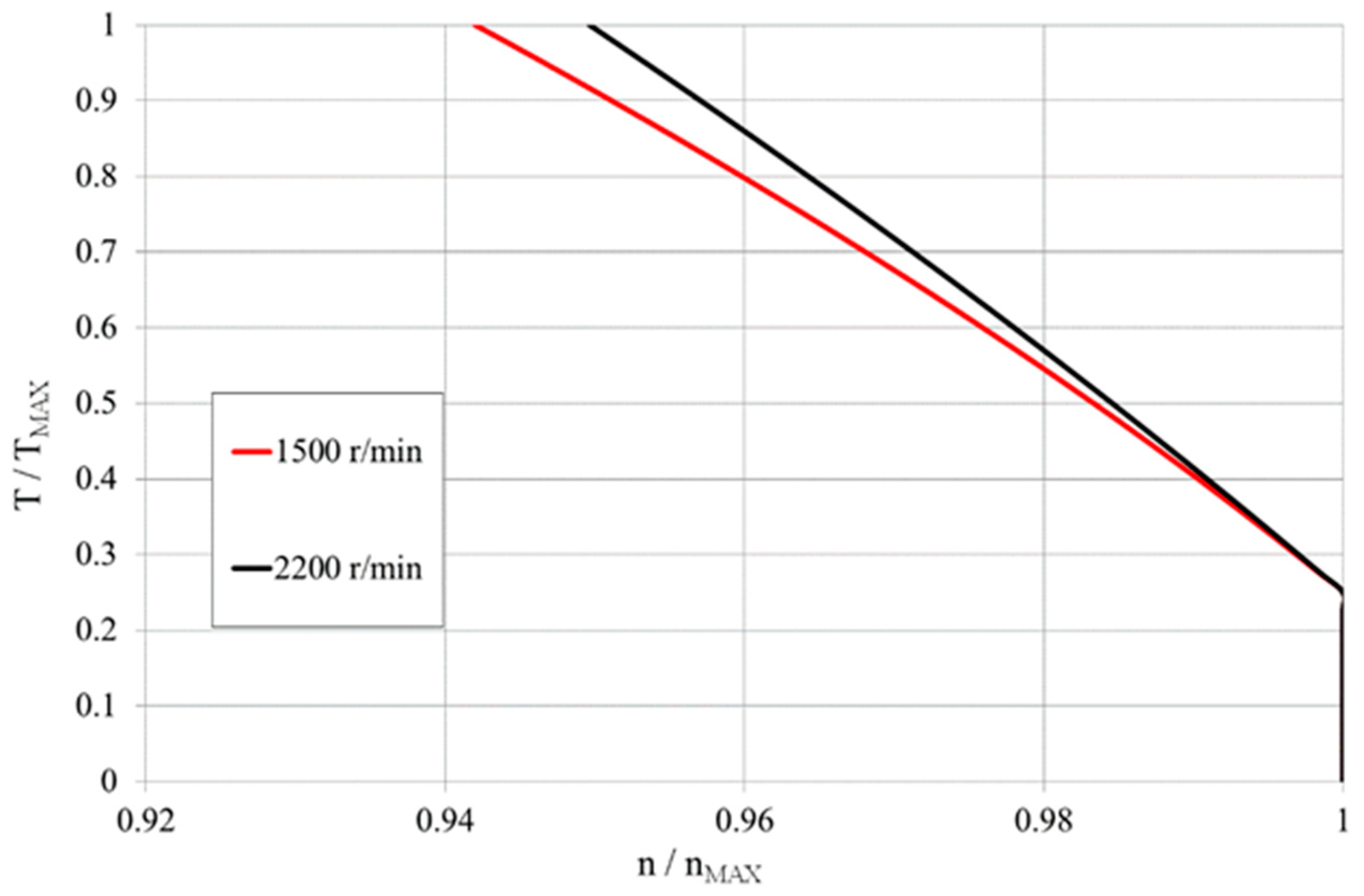
The ICE model developed calculates the instantaneous engine fuel consumption from an engine map as a function of torque and engine speed, as shown in Figure 3. The model includes the engine regulator behavior during operations, implementing the map reported in Figure 4, where the target rotational speed is reduced by a coefficient when the torque increases.
The engine map includes data from the manufacturer and data experimentally obtained.
3. Standard Excavator—Experimental Study
An extended experimental study was carried out to validate the mathematical model of the standard hydraulic excavator.
The pump and valve tests were directly performed on a test rig, as reported in [31,32,33], while to validate the hydraulic circuit tests were carried out on the excavator that was instrumented as shown in Figure 1; for more details refer to [33,34].
With reference to Figure 1, where the installed sensors are indicated, the main variables measured were: pump delivery flow rate (Qp); pump outlet pressure (p1); actuators pressures (p5 ÷ p22); turret angular velocity (ns); hydraulic actuators linear positions (y1 ÷ y3); valves main spool positions (LVDT1 ÷ LVDT6).
The experimental study carried out permitted to set the valves discharge coefficients and hydraulic line pressure drop characteristic; for the actuators and turret characterization (friction coefficients) fast and slow single movements were executed. Further detail about the experimental setup can be found in [34].
The working cycles adopted for the fuel consumption evaluation is based on the JCMAS standard [39]. To reduce the driver stochastic influence on the measurements each working cycle test considered by JCMAS was repeated a sufficient number of times in order to minimize the operator stochastic influence on the mean fuel consumption. The mean fuel consumption and the combined standard uncertainty including the instrument uncertainty (UIN) and the influence of the driver on fuel consumption (), were defined for each working cycle with a 95% confidence level, Equation (10).
To evaluate the fuel consumption prediction of the model, experimental data and simulation results are expressed as a percentage differences, Table 1 shows differences that are in the range of the standard uncertainty.
The modelling results are within the combined uncertainty limits experimentally defined in [28]. Starting from the described excavator mathematical model, a new model developing DDH solution has been studied; many components like diesel engine, front equipment, actuators and pipes (when considered) remain unchanged.
4. Zonal Hydraulics—DDH Solutions
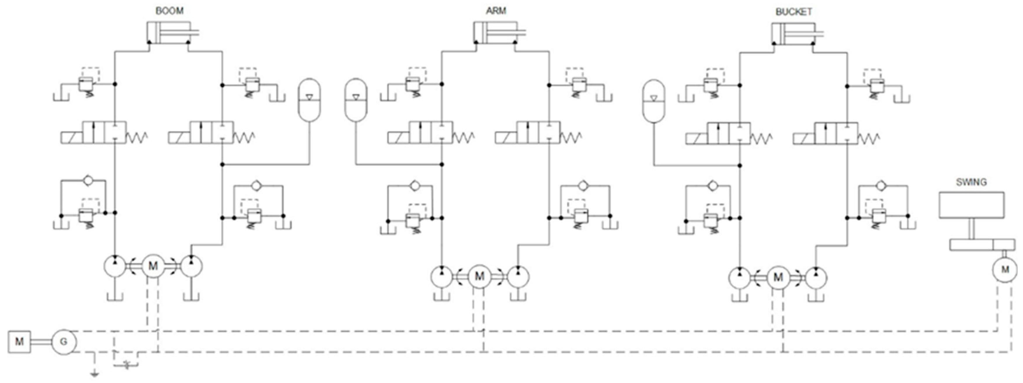
A solution based on zonal hydraulics has been modelled and the results have been compared with the standard LS circuit results. In Figure 5 a scheme of system layout is reported: the main components are two hydraulic pump/motor units at constant displacement both connected to an electric machine, a hydraulic accumulator, two anti-shock and anti-cavitation valves and two on/off valves.
The same scheme is used for all subsystems of the front equipment, except for the hydraulic accumulator connection. The hydraulic accumulator has been added for compensating the uneven flow required by a differential cylinder [19,40,41].
The accumulator has been connected to the cylinder side with lower average pressure during the duty cycle considered. For the boom cylinder the piston side presents the lower average pressure value respect to the piston side, while for the arm and cylinder, the accumulator has been placed on the piston side. For these cylinders, analyzing the cylinder pressure during the duty cycle emerges that the average pressure is lower on the piston side, because of the higher surface of piston respect the annular surface of the piston on the rod side. About the turret, a simple electric motor has been considered instead of the hydraulic motor, Figure 5. The tracks have not been considered. The DDH solution permits to remove the directional valves and the main variable displacement pump. The Diesel engine is now connected to a generator that supplies the energy to the electric motors.
The DDH mathematical model has been developed in the AMESim environment modifying the mathematical model of the standard hydraulic excavator, in this way the models of the front equipment, turret, pipe and actuators previously validated. The cylinder models remain the same as for standard configuration of excavator also for the DDH solutions, as shortly reported in previous sections, remain suitable for the new model based on the proposed DDH solution. This section is focused on the new components added to the circuit.
The pumps/motors are external gear machines modelled considering the volumetric and hydro-mechanical efficiency as a function of speed and working pressure based on standard library provided in AMESim© environment. A simple map-based model has been considered for the simulation, which is obtained from previous experimental study.
Focusing on a single subsystem, the sizing of the pump/motors has been performed considering the actual displacement of the double acting actuator, the ratio piston/rod displacement must be not too far from the ratio between the displacement of the hydraulic machine connected to the piston side and the rod side. The difference between these ratios should be less than 2% [40,41]. Considering the internal leakages of each component a flow rate compensation must be adopted, for this reason, the scheme presents a hydraulic accumulator connected to the actuator to balance this flow difference.
The pressure time derivative inside the hydraulic accumulator volume is calculated considering an adiabatic gas transformation Equation (11):
The pump/motor machine permits to recover energy during the overrunning load, the connected electric machine can work as generator. Two on/off valves have been installed to maintain the position of the actuator when not used, obviously, these valves must be simultaneously activated and deactivated. The pressure losses due to the passage through these valves have been considered. Note: utilized valves are from standard library of AMESim ©.
4.1. Operator Model
The operator mathematical model can reproduce the duty cycle proposed by the JCMAS standard [39].
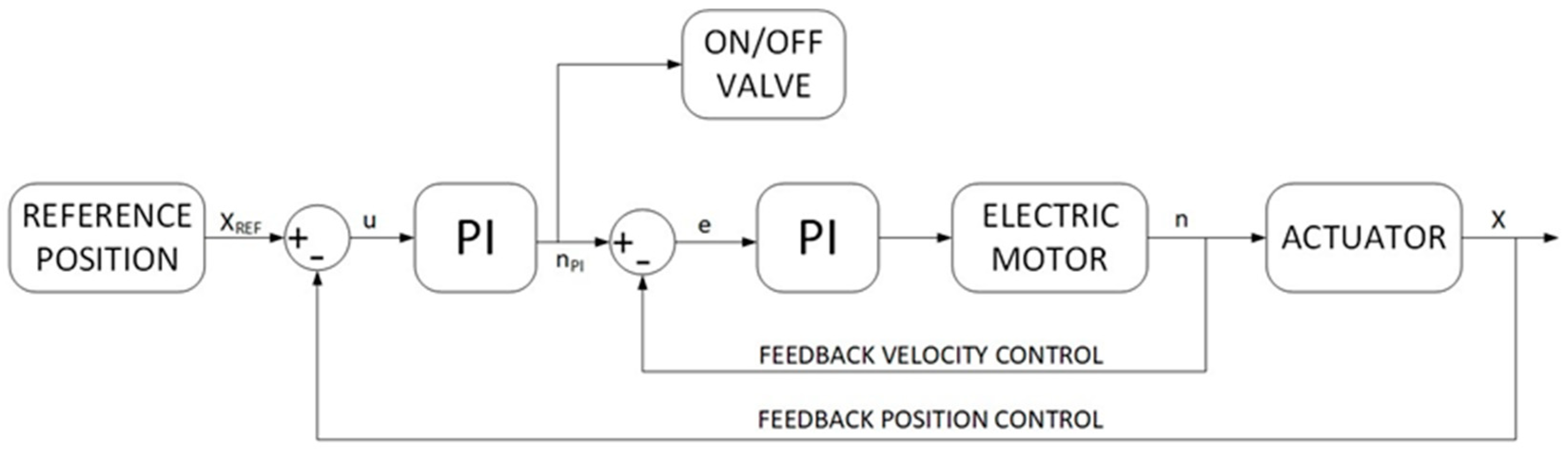
In the standard model, in order to reproduce the desired duty cycles, the actuator position is compared with the target position and a suitable spool position of the directional valve is defined. In the studied DDH solutions the position of the actuator depends on the delivered flow rates that are a function of the pump speed, this latter controlled by the electric motor. The required actuator position and the actual position define an error that is managed by a PI controller to set the electric motor speed, Figure 6.
The turret is directly moved by an electric motor. The simulation of the energy required by the turret is necessary when the digging cycle is considered. During the turret rotation the inertia of the turret has been calculated considering the front equipment in a fixed position.
4.2. Electric Components
The electric circuit is composed of three electric motors/generators, battery and the main generator connected to the diesel engine. The model was developed in AMESim© environment.
The electric motor/generator model can reproduce the working conditions in all four quadrants of the torque-speed map.
A particular working condition the electric motor speed is set to zero, because the actuator velocity must be zero. In this case the on/off valves are closed, therefore the pressure inside the pump between valves and pump/motor remain high. The electric machine must supply torque to the hydraulic machine for keeping the speed equal zero. Utilized AMESim© electric machine model permits to operate in motoring and generator mode and harvest potential energy if there are any.
In Table 2 the main simulated features of the electric motors are reported, all motors are the same for all subsystems.
In Table 2 are also reported the main features of the generator connected to the diesel engine.
4.3. Battery
This paper is not focused on the performance of the battery that is simply simulated as an ideal storage system without considering its dynamic behavior, ageing problems, thermal effects and so on. The storage system is essential to permit energy recovery during phases with overrunning loads. From the literature [42], a suitable Li-Ion battery could have the main features reported in Table 2. During simulations, it is important that the state of charge of the battery (SOC) remains always between the 30% and 80% [42]; the proper sizing of the battery permits to respect these conditions.
5. Results
This section presents the results obtained with the standard LS and DDH model to compare their performance. About the DDH solution, two configurations have been considered. A first configuration (DDH pipe) considers the presence of the same pipes adopted for the standard solution, being the electro-hydraulic cylinder drives placed on the turret, in order to introduce minimal modifications to the standard layout. The second configuration (DDH) considers the electro-hydraulic units directly connected to the cylinders for reducing the pipes losses, but it will involve a reduction of the payload capacity. In the following diagrams, the first solution is identified with the added term “pipe” in the legends. A further configuration considers an ICE downsizing for evaluating the impact on fuel consumption. A downsizing of the diesel engine is possible because of the presence of the battery that permits to limit the power peaks required to the ICE during the duty cycles, and in more efficient solutions, DDH without pipes, the maximum power request is anyway reduced.
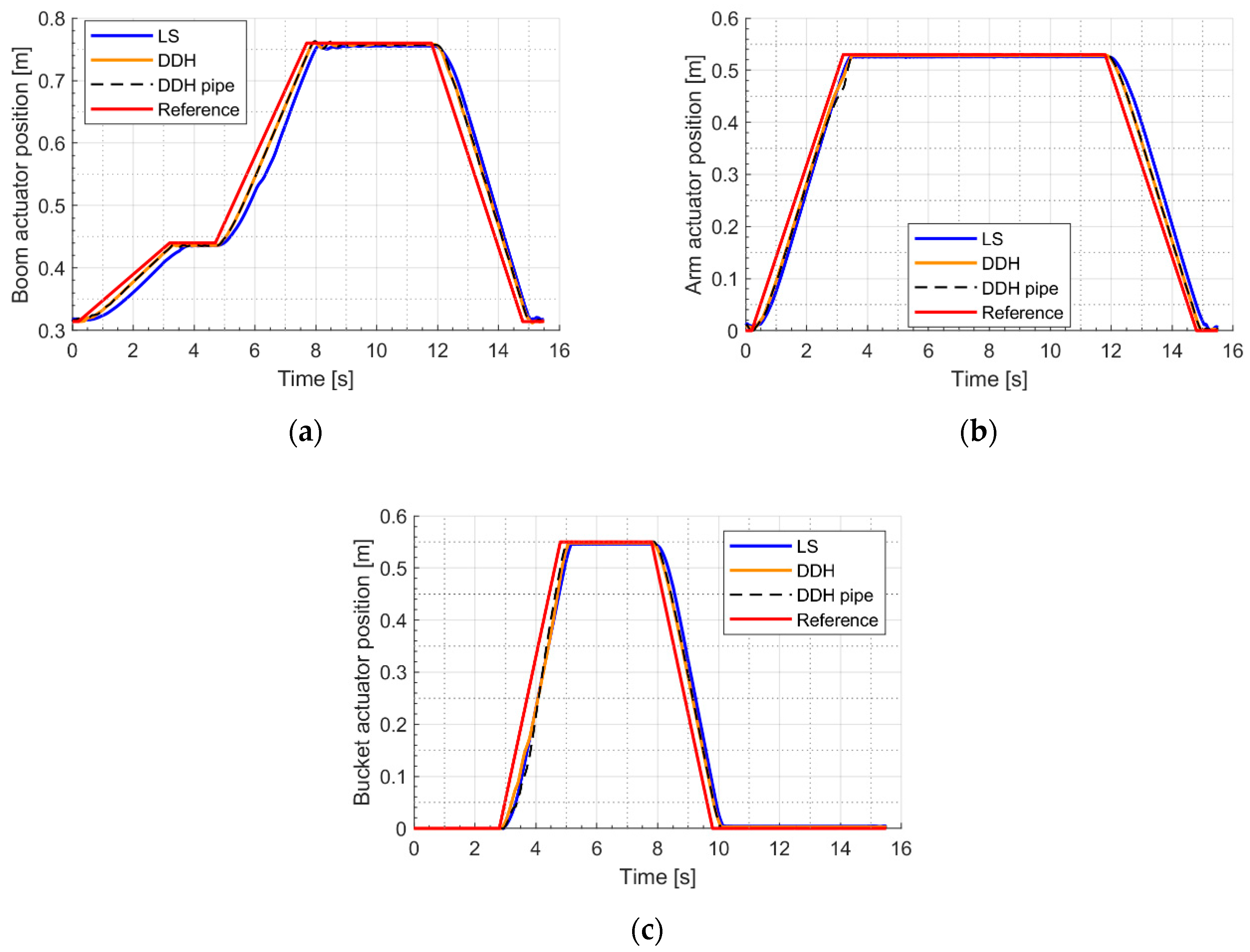
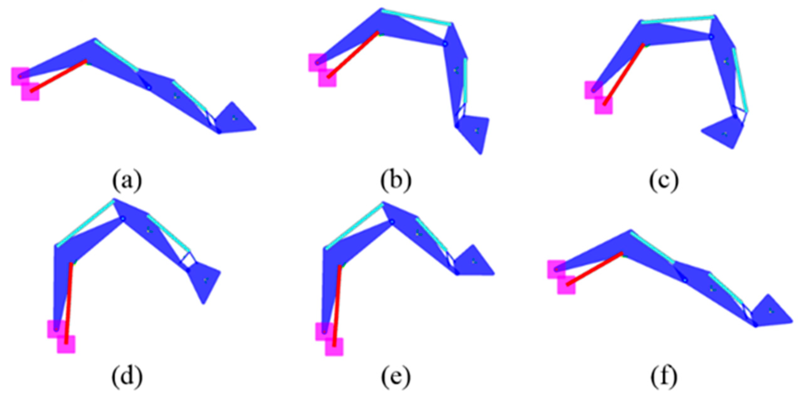
In Figure 7, the response to the digging duty cycle imposed to the front equipment actuators are represented. According to the Figures, all models, the standard LS and the two DDH, are able to follow the duty cycles without significant difference in respect to the reference one. Therefore, these results permit a reliable fuel consumption comparison between the LS and DDH architecture. Figure 8 reports the operation sequence of the front implement during the digging cycle and the relative positions of cylinders during the cycle. The cycle consists of digging a bucket of earth, the bucket opening and discharging, and going back to the initial position as displayed in Figure 8. Note: The swinging motion is excluded in this investigation, due to the focus on the front attachment of the excavator. Figure 8 is obtained from the AMESim© environment.
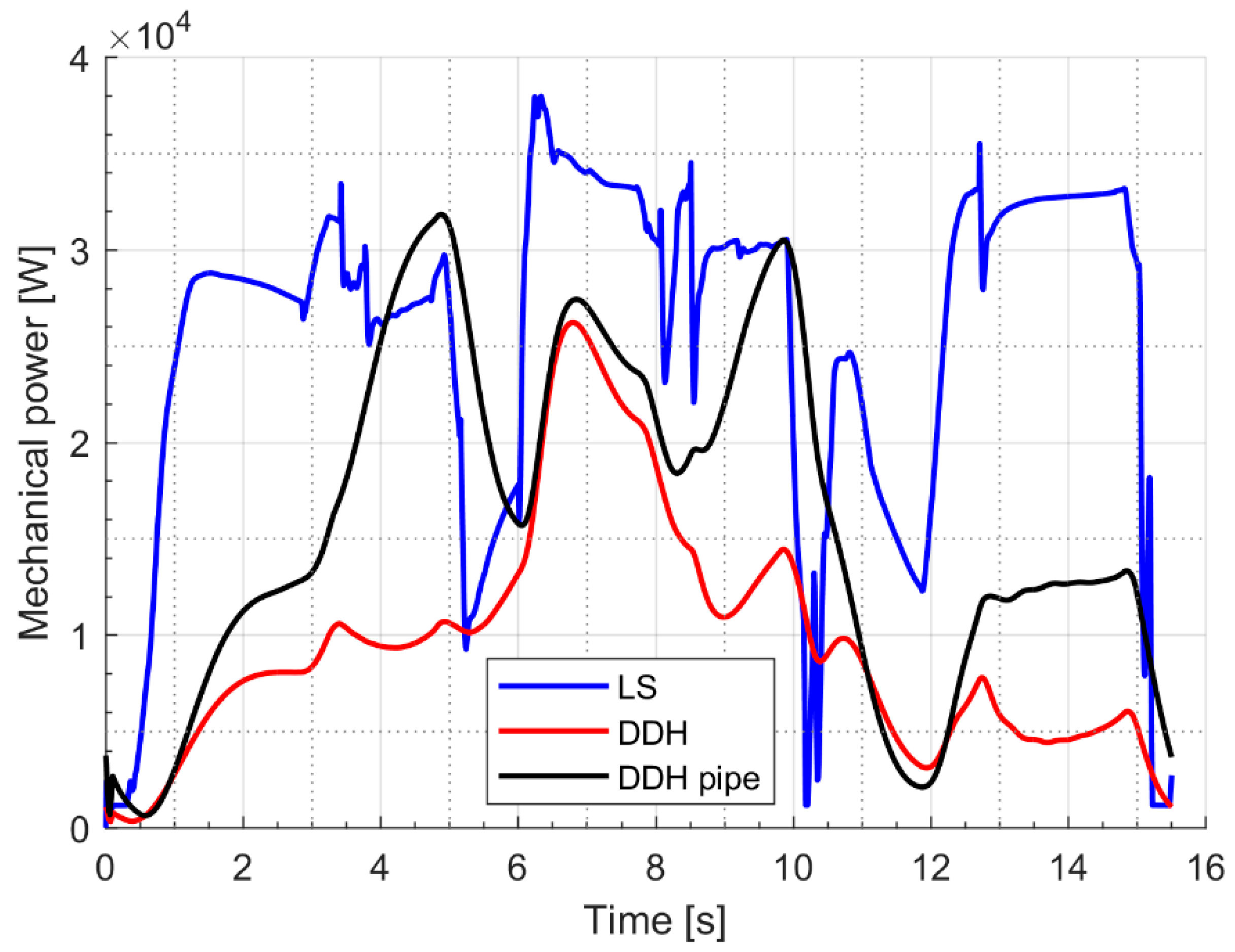
In Figure 9, the mechanical power required by the pump for the LS system and by the generator for DDH solutions is reported during a digging cycle. It is evident that the maximum mechanical power is always reduced in the case of DDH solutions; moreover, for DDH without pipes the power peak is limited to 26 kW instead of 37 kW. The lower power request will permit the investigation of a reduction of the diesel engine size.
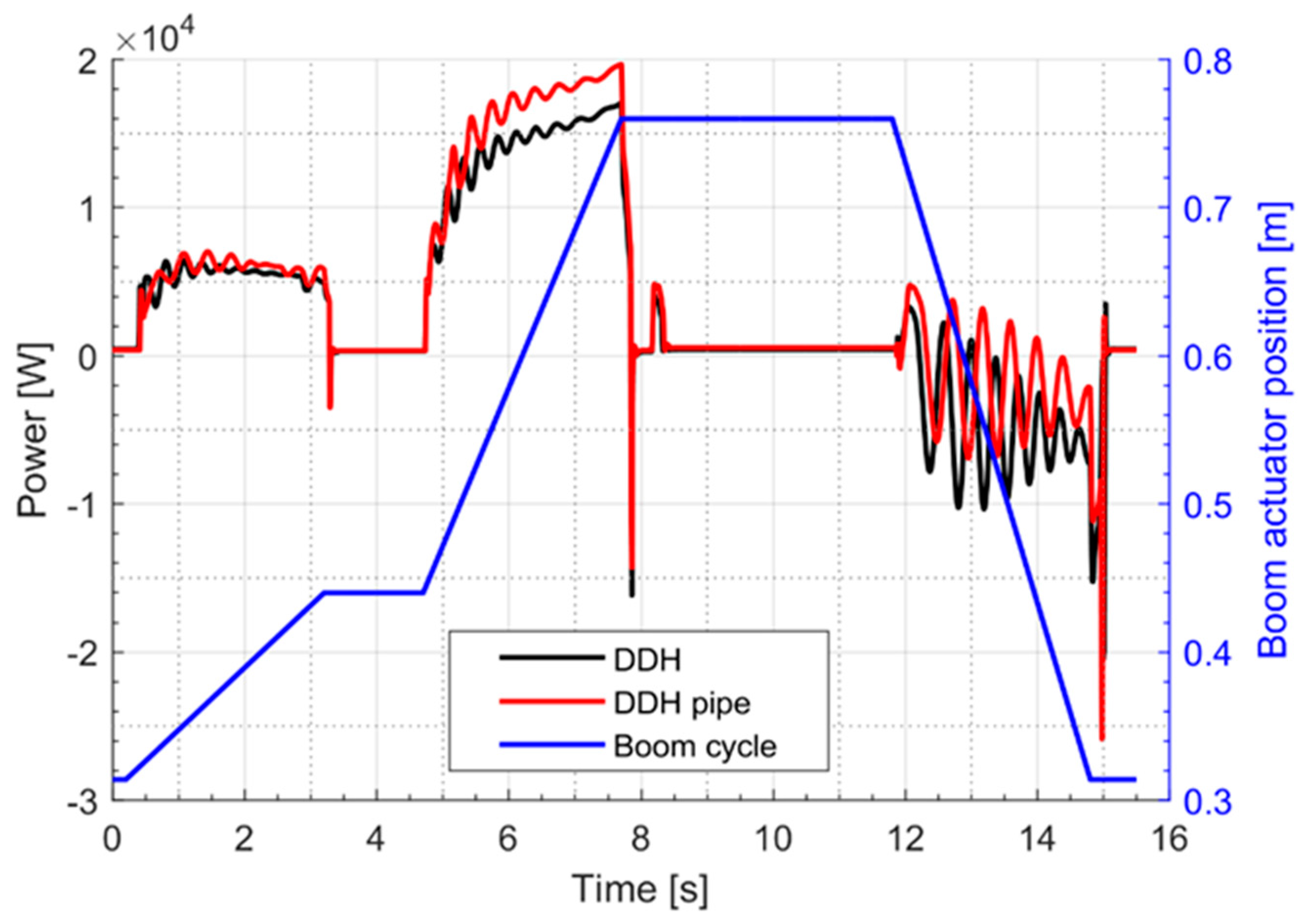
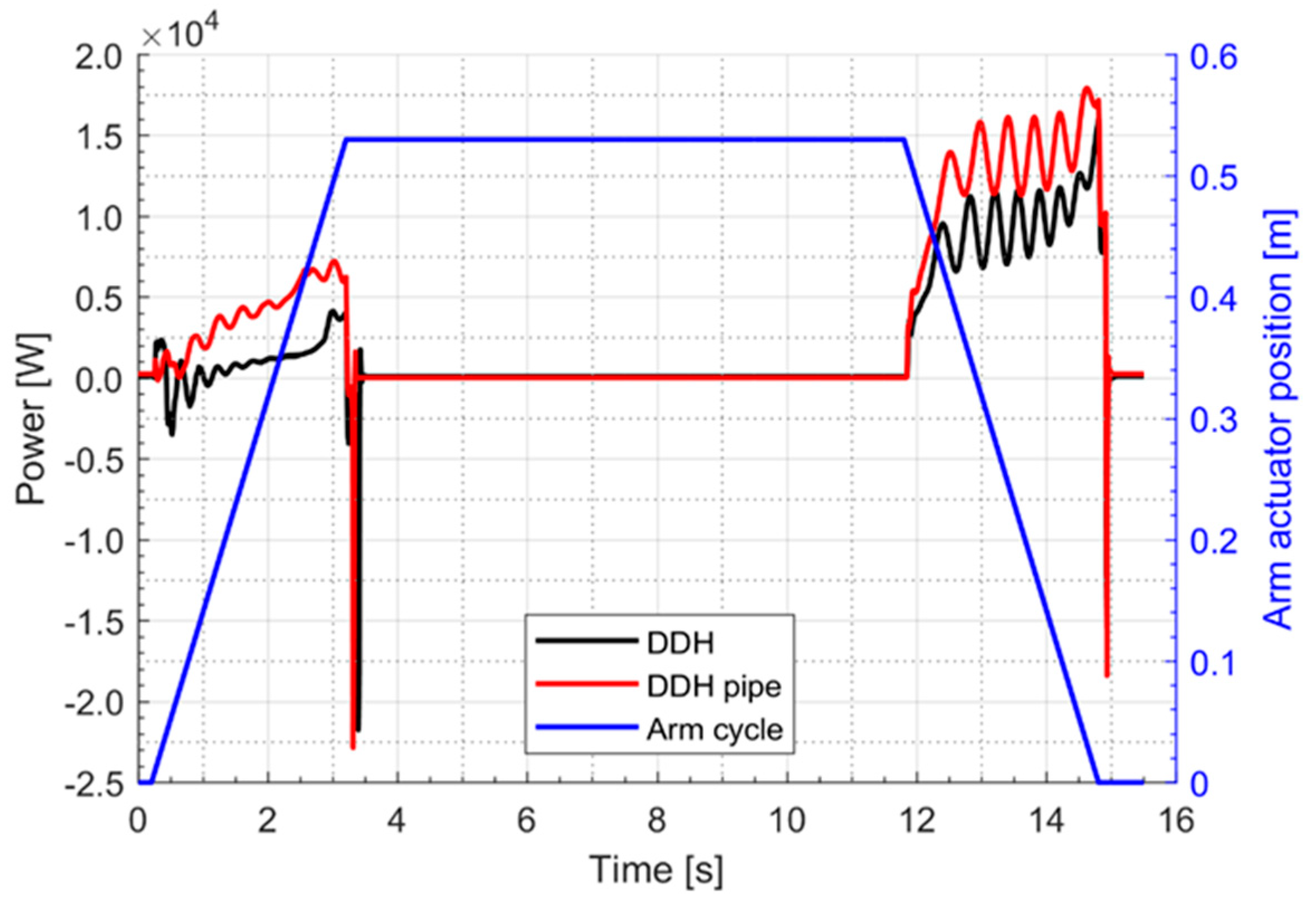
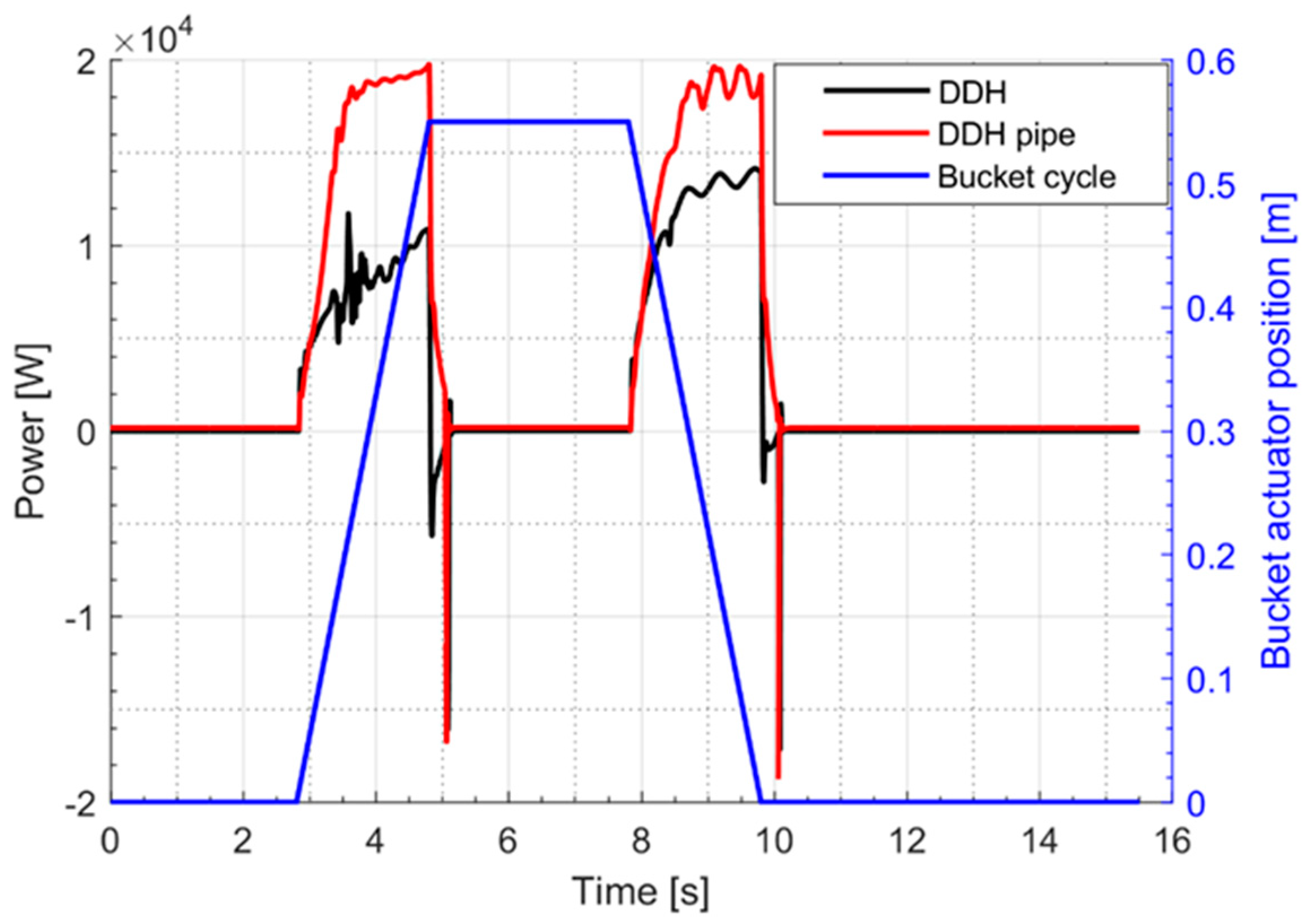
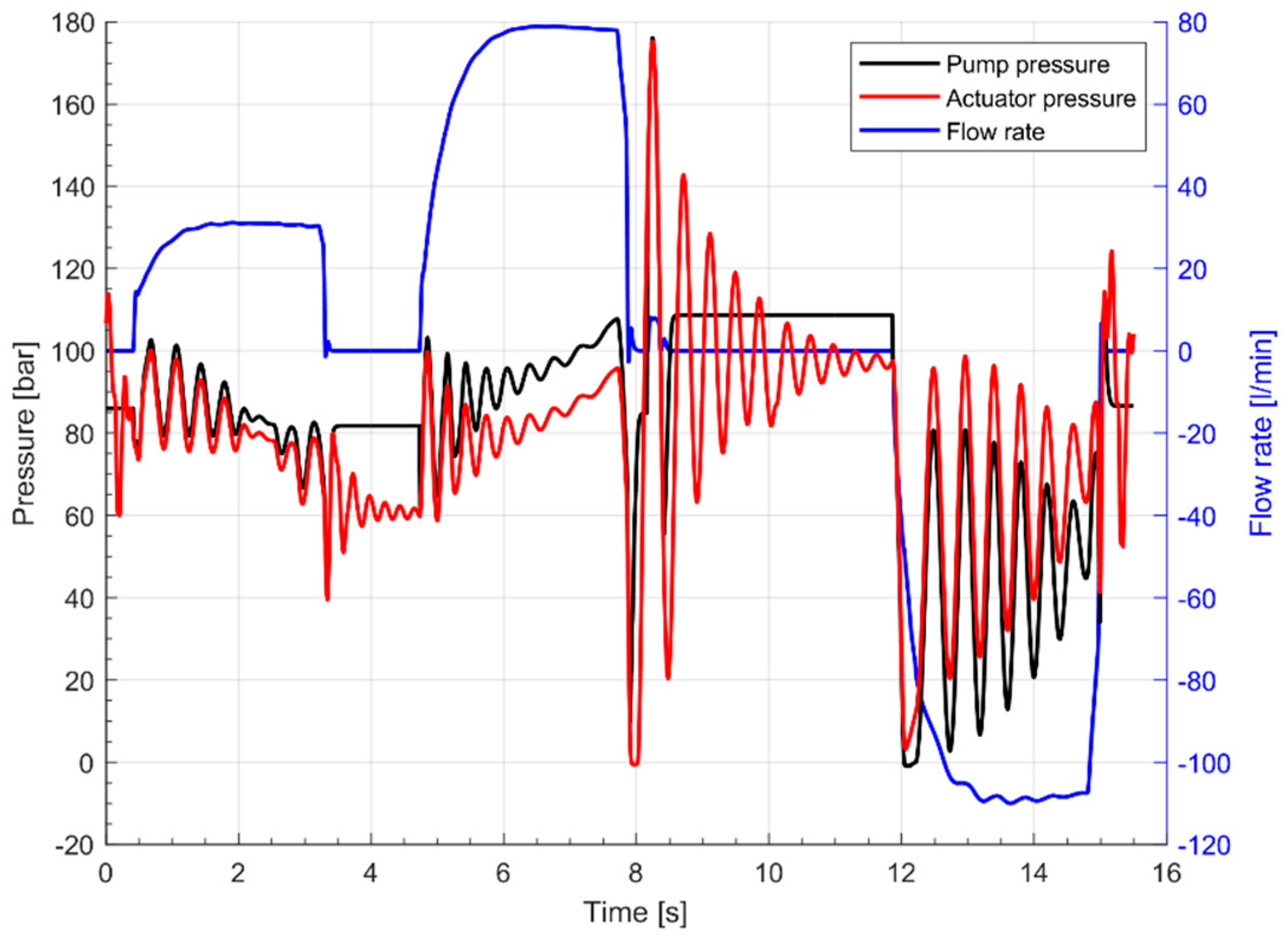
Figure 10, Figure 11 and Figure 12 report the electric motor power curves relatively to the actuation of boom, arm and bucket, respectively. In both cases of arm and bucket duty cycle the power is always positive, while for the boom case the power becomes negative during the last phase because of the overrunning load. Both the DDH and the DDH with pipes have been considered. The curves referring to the DDH with pipes always shows higher values in respect to the case without pipes, confirming the negative effects of the pipe losses. The pipe losses associated to the bucket are the most relevant, mainly because of the length/diameter ratio of the used pipes that is twice the ratio of the pipes used for the boom. Figure 13 reports the boom actuator piston side pressure during the digging cycle for the case of the DDH with pipes. The pump pressure is also reported and the differences between them are due to the pressure losses through the pipe. Such a diagram points out the negative effect of the pressure drop due to the losses through the pipes.
The main target of the simulations is to compare the energy required by the LS circuit and the DDH circuits.
In Table 3, the comparison is focused on the mechanical energy required by the pumps. In more detail, the values represent the energy required by the main pump of the LS solution, while for the DDH solution the indicated values are the sum of the energy required by all pumps involved during the considered duty cycle. From the results obtained it is evident that DDH solutions present a strong reduction of the required mechanical energy, because of the absence of the directional valves and pressure compensators. In Table 4 the comparison is referred to the diesel engine fuel consumption, in this case, the efficiency map of the engine is considered. The differences are significant but present lower values in terms of fuel saving percentage with respect to the mechanical energy saving. The reason is the effect of the engine efficiency map that presents different values depending on the load (torque) values. Thanks to the reduced power required, the diesel engines’ average load is lower with respect to the traditional LS case; unfortunately, as it is well known, at lower loads the engine features lower efficiency. A significant improvement can be obtained by reducing the engine size (cases identified with DS in the table), in this way the engine works at average loads closer to the maximum engine load where the efficiency reaches the higher values.
In Table 5, the mechanical energy supplied by the diesel engine is reported; obviously, the LS value is equal to the value reported in Table 4, being the diesel engine directly connected to the pump. For DDH solutions the l engine is connected to the generator that feeds the electric motors, the differences between Table 3 and Table 5 are due to the efficiency considered for the electric components.
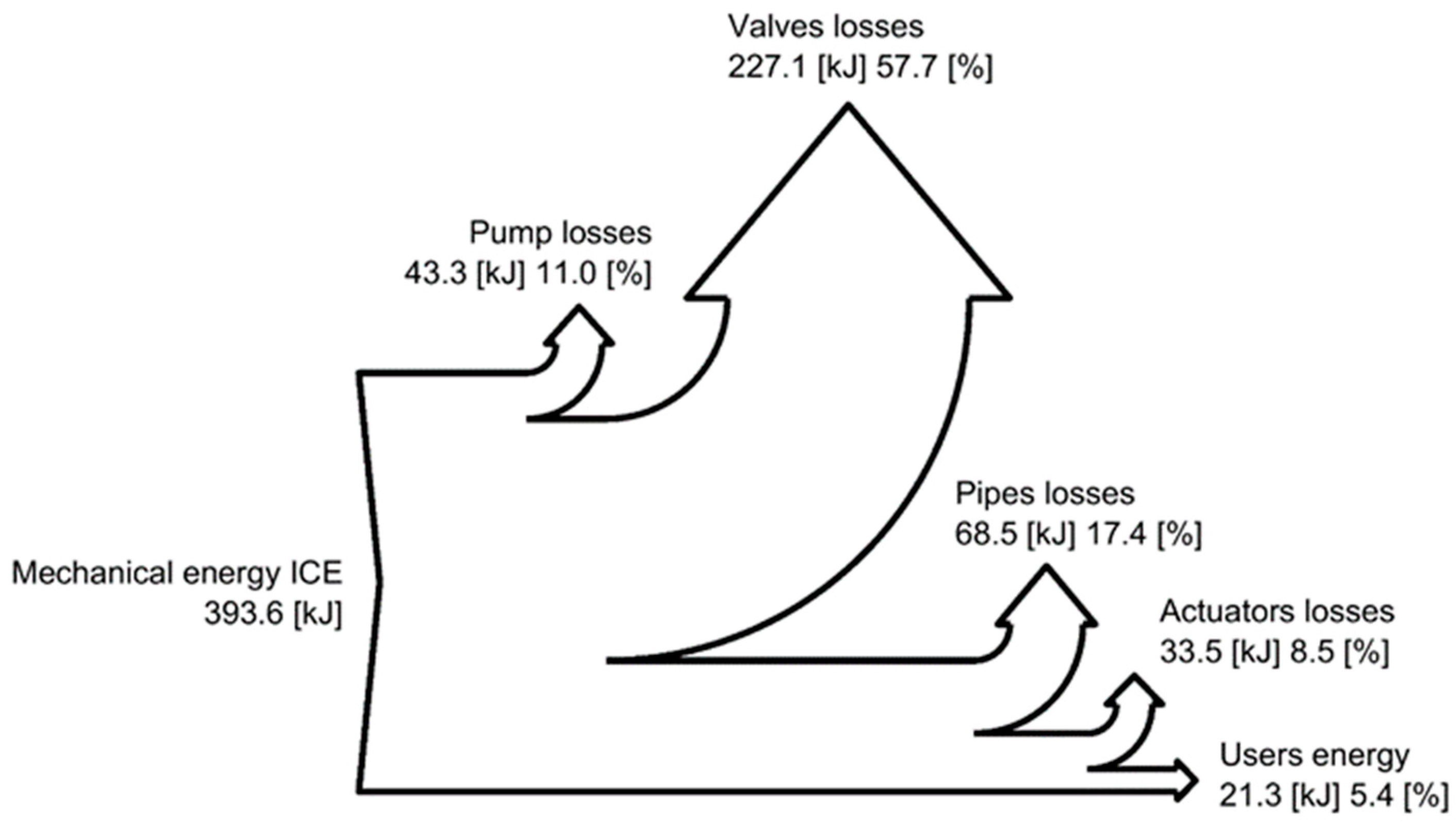
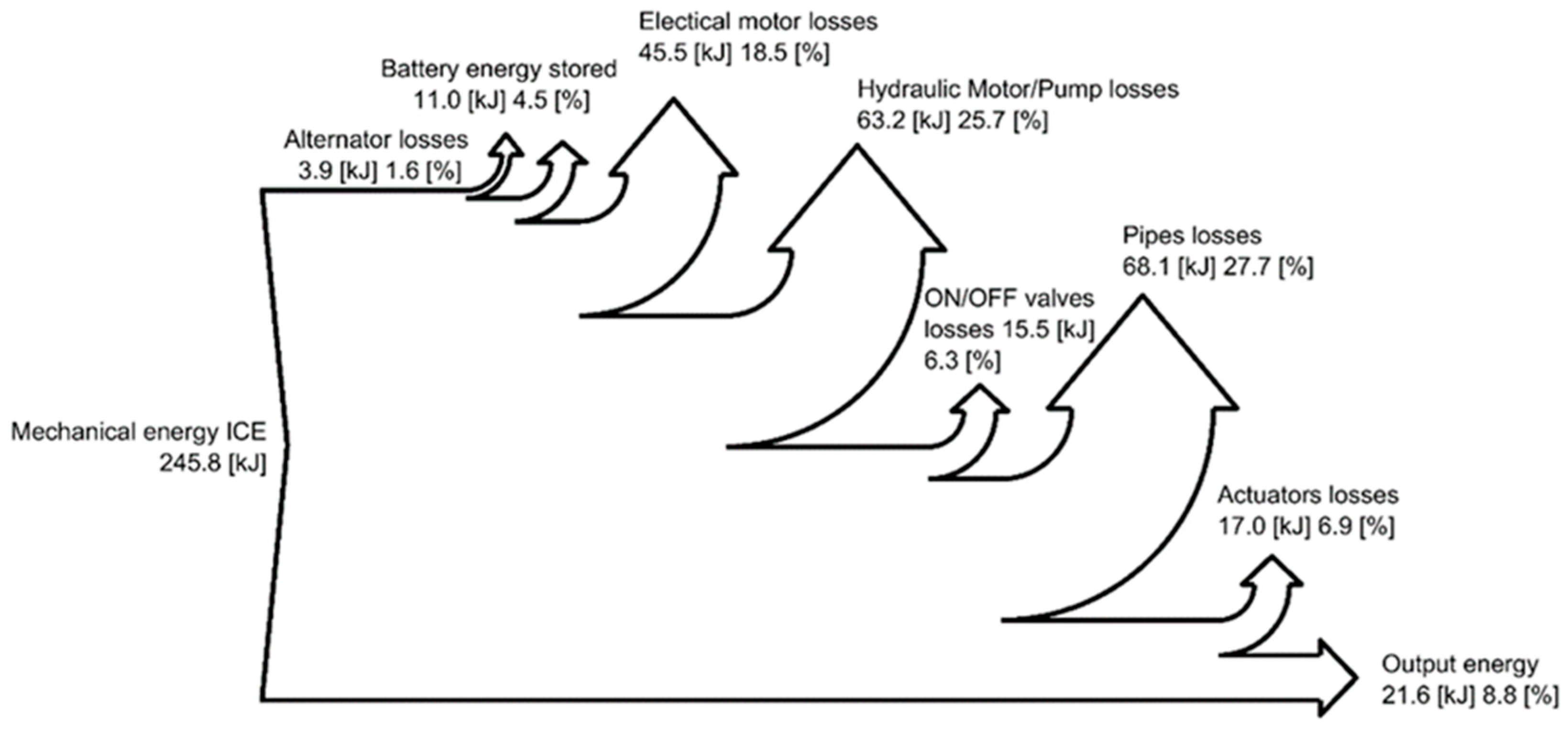
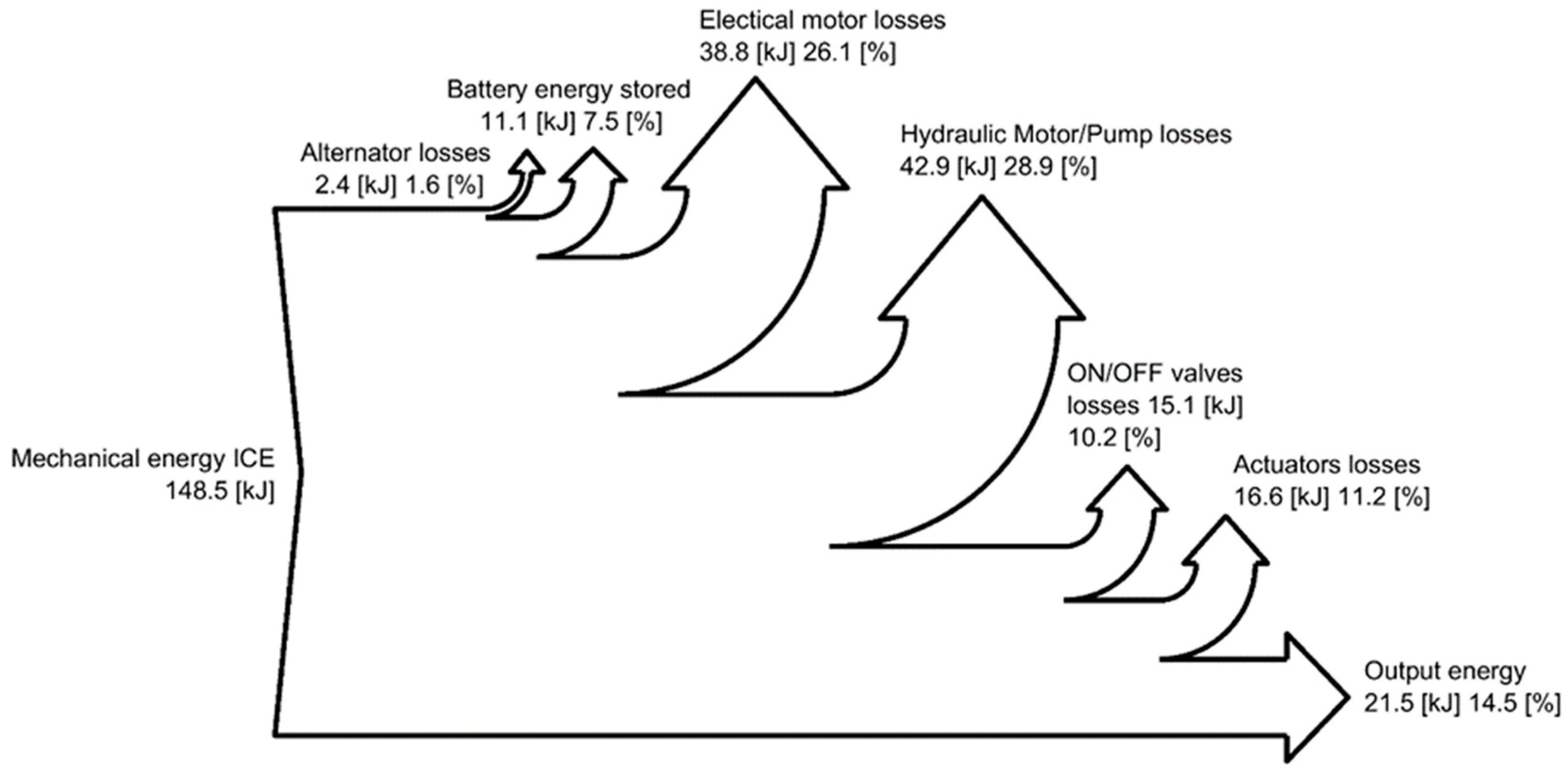
In Figure 14, Figure 15 and Figure 16, the Sankey diagrams representing the energy distribution through the systems analyzed are reported; these diagrams allow the understanding of the losses distribution. In the standard configuration (Figure 14), the main losses are due to the valve block, while for the DDH solution with pipes (Figure 16)—the more efficient solution—the losses through the pipes become more relevant (27.7%) and similar to the losses generated by hydraulic motor/pump and electric machines.
6. Discussion
The presented work concentrated on analyzing the possible improvements in a 9-tonne excavator with the application of zonal hydraulics realized with DDH.
The results are based on simulations carried out in an AMESim© environment with a validated excavator mathematical model based on a standard LS system as reference. Two DDH configurations were considered: the first one with pipes, leaving the pumps in the turret, and a second one without pipes, assuming the location of the pumps close to the cylinders.
The distributions of the losses (Sankey diagrams) for the system components of the DDH system (with pipes and without pipes) and conventional LS system were determined for a 9-tonne excavator. It was shown that location of DDH (in particular, lengths of the pipes) affects the mechanical energy requirements by 65% of the studied excavator due to increase of friction losses. This highlights that circuit layout should be carefully considered as it is affecting efficiency and overall system consumption. Realization of zonal hydraulics does not bring full advantages if location and optimization is not taken in account. It is important to notice that the drawback of the proposed zonal hydraulics solution (identical to any electrification/hybridization) is the overall costs. Since each DDH unit requires energy source (external (battery, supercapacitor + battery) or generated locally), electric servo drive, hydraulic accumulator (balance uneven flow and/or replacement for tank), and fixed displacement pump/motors. However, demonstrated advantages illustrated in this paper compensate this drawback.
The energy efficiency of both the LS circuit and the new solution was evaluated for typical duty cycles. Simulations were performed using JCMAS digging cycle. As JCMAC standard regulates, digging cycles were performed without payloads. This brings simplification to this study, as actual digging cycles do not have penetration into the earth pile. This was excluded due to the complexity of the terra-mechanical interaction and consequent forces.
The developed mathematical model has permitted to quantify the energy saving for the DDH solution investigated and to identify the sources of losses. This work has demonstrated the potential of the application of zonal hydraulics to the 9-tonne excavator, as a scale-up compared to our previous study [22]. Future steps, in order to improve the actual mathematical model, are to develop an electric motor model within the Simcenter AMESim© environment, and in experimental validation of the proposed concept with a 1-tonne micro-excavator as the most affordable scale for testing. Further solutions will be investigated for compensating the uneven flow requirements for the differential cylinder application.
7. Conclusions
In this paper an investigation of the implementation of zonal hydraulics with direct driven hydraulics (DDH) for a 9-tonne excavator is presented. The results are based on simulations carried out with a validated excavator mathematical model based on a standard LS system assumed as reference. Two DDH configurations were considered: the first one with pipes, leaving the pumps in the turret, and a second one without pipes, assuming the placing of the pumps close to the cylinders. The mathematical model has permitted to quantify the energy saving for each solution investigated and to identify the sources of losses.
The absence of the directional valves, with their pressure compensators, has strongly reduced the hydraulic losses; in this case, it clearly emerges that the pipes losses become relevant. Therefore, a DDH solution should be developed by locating the pumps as close as possible to the cylinders.
In both the DDH analyzed solutions the mechanical power presents the lower maximum values, and this result permits us to reduce the displacement of the diesel engine, with the main advantages of increasing the efficiency and reducing the engine mass/size, partially compensating for the presence of electric components.
Author Contributions
Conceptualization, P.C. and T.M.; methodology, P.C.; software, F.S.; validation, P.C. and F.S.; writing—original draft preparation, P.C., T.M. and M.R.; writing—review and editing, P.C., T.M. and M.R.; supervision, P.C.; project administration, P.C. All authors have read and agreed to the published version of the manuscript.
Funding
This research received no external funding.
Acknowledgments
The authors would like to acknowledge Casappa S.p.A. for the active support given to the experimental activity on the hydraulic excavator.
Conflicts of Interest
The authors declare no conflict of interest.
Nomenclature
| Abbreviation | Definition | |
| BSFC | Brake Specific Fuel Consumption | |
| DS | ICE downsizing | |
| DDH | Direct Driven Hydraulics | |
| ICE | Internal Combustion Engine | |
| JCMAS | Japan Construction Machinery Association Standard | |
| LS | Load Sensing | |
| Symbol | Definition | Unit |
| B | Fluid Bulk Modulus | (Pa) |
| bt | Turret Viscous Friction Coefficient | (N·m/(rad/s)) |
| bx, by | Contact Damping Coefficient | (N/(m/s)) |
| dp | Actuator Piston Diameter | (m) |
| ey | Actuator Position Error | (m) |
| It | Turret Moment of Inertia | (kg·m2)] |
| kx, ky | Contact Stiffness Coefficient | (N/m) |
| p | Pressure | (Pa) |
| Q | Flow Rate | (m3/s) |
| Standard Deviation of the Mean | (kg) | |
| UIN | Instrument Uncertainty | (kg) |
| UC95 | Combined Standard Uncertainty | (kg) |
| Tt | Torque turret | (N·m) |
| TCt | Turret Coulomb Friction Torque | (N·m) |
| T | Hydraulic Machine Torque | (N·m) |
| V | Volume | (m3) |
| ϑ | Angular Position | (rad) |
| µ | Fluid Dynamic Viscosity | (Pa·s) |
References
- Vukovic, M.; Leifeld, R.; Murrenhoff, H. Reducing Fuel Consumption in Hydraulic Excavators—A Comprehensive Analysis. Energies 2017, 10, 687. [Google Scholar] [CrossRef] [Green Version]
- Inderelst, M.; Weidner, F.; Niu, D.; Stammen, C. Quantification of Energy Saving Influencers. 21t Excavator Hydraulic System–A Holistic Investigation? In Proceedings of the 11th International Fluid Power Conference, Aachen, Germany, 19–21 March 2018. [Google Scholar]
- Joo, C.; Stangl, M. Application of Power Regenerative Boom system to excavator. In Proceedings of the 10th IFK: International Fluid Power Conference, Dresden, Germany, 8–10 March 2016; Volume 3, pp. 175–184. [Google Scholar]
- Li, J.; Zhao, J.; Zhang, X. A Novel Energy Recovery System Integrating Flywheel and Flow Regeneration for a Hydraulic Excavator Boom System. Energies 2020, 13, 315. [Google Scholar] [CrossRef] [Green Version]
- Cheng, G.U.; Xiao, X.U.; Xiao, L.I.; Shou-Hong, W.A. Recovering system of swing braking energy in hydraulic excavator. J. Zhejiang Univ. 2012, 46, 142–149. [Google Scholar] [CrossRef]
- Chengqiang, L.; Yong, W.; Yong, D.; Yi, S. Simulation and Experimental Research on Slewing System Energy Saving of Hydraulic Hybrid Excavator. In Proceedings of the 2019 IEEE 8th International Conference on Fluid Power and Mechatronics (FPM), Wuhan, China, 10–13 April 2019; pp. 177–182. [Google Scholar] [CrossRef]
- Leon-Quiroga, J.; Newell, B.; Krishnamurthy, M.; Gonzalez-Mancera, A.; Garcia-Bravo, J. Energy Efficiency Comparison of Hydraulic Accumulators and Ultracapacitors. Energies 2020, 13, 1632. [Google Scholar] [CrossRef] [Green Version]
- Padovani, D.; Rundo, M.; Altare, G. The Working Hydraulics of Valve-Controlled Mobile Machines: Classification and Review. J. Dyn. Sys. Meas. Control 2020, 142, 070801. [Google Scholar] [CrossRef]
- Rosero, J.; Ortega, J.; Aldabas, E.; Romeral, L. Moving Towards a more Electric Aircraft. IEEE Aerosp. Electron. Syst. Mag. 2007, 22, 3–9. [Google Scholar] [CrossRef] [Green Version]
- Gaile, A.; Lue, Y. Electro Hydraulic Actuation (EHA) systems for primary flight control, landing gear and other type of actuation. In Proceedings of the 2016 IEEE International Conference on Aircraft Utility Systems (AUS), Beijing, China, 10–12 October 2016; pp. 723–728. [Google Scholar] [CrossRef]
- Schneider, M.; Koch, O.; Weber, J. Green Wheel Loader–Improving fuel economy through energy efficient drive and control concepts. In Proceedings of the 10th International Fluid Power Conference, Dresden, Germany, 8–10 March 2016. [Google Scholar]
- Smith, S.; Irving, J.; Irving, J. Electro Hydrostatic Actuators for Control of Undersea Vehicles. In Proceedings of the Joint Undersea Warfare Technology Fall Conference, Groton, CT, USA, 20–23 September 2006. [Google Scholar]
- Ding, B.; Plummer, A.; Iravani, P. A Study of a Compliant Hydraulic Actuator for Running Robots. In Proceedings of the 2018 Global Fluid Power Society PhD Symposium (GFPS), Samara, Russia, 18–20 July 2018; pp. 1–6. [Google Scholar] [CrossRef]
- Imam, A.; Rafiq, M.; Jalayeri, E.; Sepehri, N. A Pump-Controlled Circuit for Single-Rod Cylinders that Incorporates Limited Throttling Compensating Valves. Actuators 2018, 7, 13. [Google Scholar] [CrossRef] [Green Version]
- Schmidt, L.; Ketelsen, S.; Brask, M.H.; Mortensen, K.A. A Class of Energy Efficient Self-Contained Electro-Hydraulic Drives with Self-Locking Capability. Energies 2019, 12, 1866. [Google Scholar] [CrossRef] [Green Version]
- Padovani, D.; Ketelsen, S.; Hagen, D.; Schmidt, L. A Self-Contained Electro-Hydraulic Cylinder with Passive Load-Holding Capability. Energies 2019, 12, 292. [Google Scholar] [CrossRef] [Green Version]
- Li, Y.; Jiao, Z.; Wang, Z. Design, Analysis, and Verification of an Electro-Hydrostatic Actuator for Distributed Actuation System. Sensors 2020, 20, 634. [Google Scholar] [CrossRef] [Green Version]
- Takahashi, N.; Kondo, T.; Takada, M.; Masutani, K.; Okano, S.; Tsujita, M. Development of Prototype Electro-Hydrostatic Actuator for Landing Gear Extension and Retraction. In Proceedings of the 7th JFPS International Symposium on Fluid Power, Toyama, Japan, 15–18 September 2008. [Google Scholar]
- Ketelsen, S.; Padovani, D.; Andersen, T.O.; Ebbesen, M.K.; Schmidt, L. Classification and Review of Pump-Controlled Differential Cylinder Drives. Energies 2019, 12, 1293. [Google Scholar] [CrossRef] [Green Version]
- Abekawa, T.; Tanikawa, Y.; Hirosawa, A. Introduction of Komatsu Genuine Hydraulic Oil KOMHYDRO HE; Komatsu Technical Report; Komatsu: Tokyo, Japan, 2010; Volume 56. [Google Scholar]
- Niraula, A.; Zhang, S.; Minav, T.; Pietola, M. Effect of zonal hydraulics on energy consumption and boom structure of an excavator. Energies 2018, 11, 2088. [Google Scholar] [CrossRef] [Green Version]
- Zhang, S.; Minav, T.; Pietola, M. Improving efficiency of micro excavator with decentralized hydraulics. In Proceedings of the 2017 Bath/ASME Symposium on Fluid Power and Motion Control, FPMC 2017, Sarasota, FL, USA, 16–19 October 2017. [Google Scholar]
- Rundo, M. Models for Flow Rate Simulation in Gear Pumps: A Review. Energies 2017, 10, 1261. [Google Scholar] [CrossRef] [Green Version]
- Borghi, M.; Zardin, B.; Specchia, E. External Gear Pump Volumetric Efficiency: Numerical and Experimental Analysis. SAE Tech. Pap. 2009, 1, 2844. [Google Scholar] [CrossRef]
- Frosina, E.; Buono, D.; Senatore, A.; Costin, I.J. A Simulation Methodology Applied on Hydraulic Valves for High Fluxes. Int. Rev. Model. Simul. 2016, 9, 217. [Google Scholar] [CrossRef]
- Frosina, E.; Senatore, A.; Rigosi, M. Study of a High-Pressure External Gear Pump with a Computational Fluid Dynamic Modeling Approach. Energies 2017, 10, 1113. [Google Scholar] [CrossRef] [Green Version]
- Altare, G.; Rundo, M. CFD Analysis of gerotor lubricating pumps at high speed: Geometric features influencing the filling capability. In Proceedings of the ASME/BATH 2015 Symposium on Fluid Power and Motion Control (FPMC), Chicago, IL, USA, 12–14 October 2015. Paper no. FPMC2015-9539. [Google Scholar] [CrossRef]
- Pintore, F.; Borghi, M.; Morselli, R.; Benevelli, A.; Zardin, B.; Belluzzi, F. Modelling and Simulation of the Hydraulic Circuit of an Agricultural Tractor. In Proceedings of the 8th FPNI Ph.D Symposium on Fluid Power, Lappeenranta, Finland, 11–13 June 2014. [Google Scholar] [CrossRef]
- Casoli, P.; Anthony, A. Gray Box Modeling of an Excavator Variable Displacement Hydraulic Pump for Fast Simulation of Excavation Cycles; Control Engineering Practice; Elsevier Ltd.: Amsterdam, The Netherlands, 2013; Volume 21, pp. 483–494. [Google Scholar] [CrossRef]
- Casoli, P.; Gambarotta, A.; Pompini, N.; Riccò, L. Development and application of co-simulation and control-oriented modeling in the improvement of performance and energy saving of mobile machinery. Energy Procedia 2014, 45, 849–858. [Google Scholar] [CrossRef] [Green Version]
- Casoli, P.; Anthony, A.; Riccò, L. Modeling of an Excavator System–Load sensing flow sharing valve model. In Proceedings of the SAE 2012 Commercial Vehicle Engineering Congress, Rosemont, IL, USA, 13–14 September 2012. [Google Scholar] [CrossRef]
- Casoli, P.; Gambarotta, A.; Pompini, N.; Riccò, L. Coupling excavator hydraulic system and internal combustion engine models for the Real-Time simulation. Control Eng. Pract. 2015, 41, 26–37. [Google Scholar] [CrossRef]
- Casoli, P.; Pompini, N.; Riccò, L. Simulation of an Excavator Hydraulic System Using Nonlinear Mathematical Models. Stroj. Vestn. J. Mech. Eng. 2015, 61, 583–593. [Google Scholar] [CrossRef] [Green Version]
- Casoli, P.; Riccò, L.; Campanini, F.; Lettini, A.; Dolcin, C. Mathematical model of a hydraulic excavator for fuel consumption predictions. In Proceedings of the ASME/BATH Symposium on Fluid Power & Motion Control, Chicago, IL, USA, 12–14 October 2015; Paper No. FPMC2015-9566. ISBN 978-0-7918-5723-6. [Google Scholar] [CrossRef]
- Bedotti, A.; Campanini, F.; Pastori, M.; Riccò, L.; Casoli, P. Energy saving solutions for a hydraulic excavator. Energy Procedia 2017, 126, 1099–1106. [Google Scholar] [CrossRef]
- Casoli, P.; Riccò, L.; Campanini, F.; Bedotti, A. Hydraulic Hybrid Excavator—Mathematical Model Validation and Energy Analysis. Energies 2016, 9, 1002. [Google Scholar] [CrossRef] [Green Version]
- Casoli, P.; Anthony, A.; Rigosi, M. Modeling of an Excavator System–Semi empirical hydraulic pump model. SAE Int. J. Commer. Veh. 2011, 4, 242–255. [Google Scholar] [CrossRef]
- Ivantysyn, J.; Ivantysynova, M. Hydrostatic Pumps and Motors; Technip Books International: New Delhi, India, 2003; ISBN 81-88305-08. [Google Scholar]
- Earth-Moving Machinery—Fuel Consumption on Hydraulic Excavator—Test Procedure; JCMAS H020:2007; Japan Construction Machinery and Construction Association for Hydraulic Excavators: Tokyo, Japan, 2007.
- Järf, A.; Minav, T.; Pietola, M. Nonsymmetrical flow compensation using hydraulic accumulator in direct driven differential cylinder. In Proceedings of the ASME 2016 9th FPNI Ph.D. Symposium on Fluid Power, FPNI2016, Florianópolis, Brazil, 26–28 October 2016. [Google Scholar]
- Minav, T.; Zhang, S.; Pietola, M. Eliminating sizing error in direct-driven hydraulics. In Proceedings of the 10th JFPS International symposium on Fluid Power, Fukuoka, Japan, 24–27 October 2017. [Google Scholar]
- Rahn, C.D.; Wang, C.-Y. Battery Systems Engineering; Wiley: Hoboken, NJ, USA, 2013; ISBN 9781119979500. [Google Scholar]
Figure 1.
Standard excavator hydraulic circuit with installed sensors for testing [34].
Figure 1.
Standard excavator hydraulic circuit with installed sensors for testing [34].

Figure 2.
Control volumes considered for modelling the cylinder

Figure 3.
Diesel engine—brake specific fuel consumption map.

Figure 4.
Diesel engine—shaft speed variation with torque.

Figure 5.
Scheme of zonal hydraulic solution.

Figure 6.
Electro-hydraulic control scheme.

Figure 7.
Actuator response to reference position of duty digging cycle: simulations results (a) boom, (b) arm, (c) bucket.
Figure 7.
Actuator response to reference position of duty digging cycle: simulations results (a) boom, (b) arm, (c) bucket.

Figure 8.
(a–f) Operation sequence of the front implement during digging cycle.

Figure 9.
Mechanical power course during digging duty cycle.

Figure 10.
Electric motor power boom actuator— direct driven hydraulics (DDH) and DDH with pipes.

Figure 11.
Electric motor power arm actuator—DDH and DDH with pipes.

Figure 12.
Electric motor power bucket actuator—DDH and DDH with pipes.

Figure 13.
Boom actuator piston side, pressure and flow rate. DDH with pipes model.

Figure 14.
Sankey diagram for the digging duty cycle—standard LS solution.

Figure 15.
Sankey diagram for the digging duty cycle—DDH with pipes.

Figure 16.
Sankey diagram for the digging duty cycle—DDH without pipes.


Table 1.
Results comparison.
| Working Cycle | UC95 [%] | [%] |
|---|---|---|
| Trench Digging | ±3.6 | −0.3 |
| Grading | ±8.0 | −1.8 |
Table 2.
Electric components and their main parameters.
| Component | Parameter | Value |
|---|---|---|
| Electric motor | Voltage [V] | 400 |
| Max speed [r/min] | 4000 | |
| Moment of inertia [kg/m2] | 0.049 | |
| Generator | Min speed [r/min] | 1000 |
| Rated speed [r/min] | 2200 | |
| Voltage [V] | 400 | |
| Battery | Specific Energy [Wh/kg] | 130 |
| Specific power [W/kg] | 2000 | |
| Power [kW] | 50 | |
| Mass [kg] | 25 |
Table 3.
Mechanical energy supplied to the pumps.
| Solutions | Mechanical Energy (kJ/Cycle) | Mechanical Energy Saving (%) | ||
|---|---|---|---|---|
| Digging | Grading | Digging | Grading | |
| LS | 393.6 | 72.1 | / | / |
| DDH with pipes | 185.3 | 15.7 | −54.0 | −78.3 |
| DDH without pipes | 96.2 | 12.2 | −75.5 | −83.1 |
Table 4.
Diesel engine fuel consumption.
| Solutions | Fuel Consumption (g/Cycle) | Fuel Saving (%) | ||
|---|---|---|---|---|
| Digging | Grading | Digging | Grading | |
| LS | 34.5 | 10.5 | / | / |
| DDH with pipes | 28.2 | 8.6 | −18.2 | −18.2 |
| DDH without pipes | 24.1 | 8.6 | −30.1 | −19.7 |
| DDH (DS) with pipes | 23.8 | 7.3 | −31.1 | −31.0 |
| DDH (DS) without pipes | 17.0 | 5.9 | −50.8 | −43.6 |
Table 5.
Mechanical energy supplied by diesel engine (for DDH solutions the diesel engine is connected to the generator).
Table 5.
Mechanical energy supplied by diesel engine (for DDH solutions the diesel engine is connected to the generator).
| Solutions | Mechanical Energy (kJ/Cycle) | Mechanical Energy Saving (%) | ||
|---|---|---|---|---|
| Digging | Grading | Digging | Grading | |
| LS | 393.6 | 72.1 | / | / |
| DDH with pipes | 245.8 | 26.9 | −37.5 | −62.8 |
| DDH without pipes | 148.5 | 23.0 | −62.3 | −68.1 |
© 2020 by the authors. Licensee MDPI, Basel, Switzerland. This article is an open access article distributed under the terms and conditions of the Creative Commons Attribution (CC BY) license (http://creativecommons.org/licenses/by/4.0/).
Share and Cite
MDPI and ACS Style
Casoli, P.; Scolari, F.; Minav, T.; Rundo, M. Comparative Energy Analysis of a Load Sensing System and a Zonal Hydraulics for a 9-Tonne Excavator. Actuators 2020, 9, 39. https://doi.org/10.3390/act9020039
AMA Style
Casoli P, Scolari F, Minav T, Rundo M. Comparative Energy Analysis of a Load Sensing System and a Zonal Hydraulics for a 9-Tonne Excavator. Actuators. 2020; 9(2):39. https://doi.org/10.3390/act9020039
Chicago/Turabian StyleCasoli, Paolo, Fabio Scolari, Tatiana Minav, and Massimo Rundo. 2020. "Comparative Energy Analysis of a Load Sensing System and a Zonal Hydraulics for a 9-Tonne Excavator" Actuators 9, no. 2: 39. https://doi.org/10.3390/act9020039
Note that from the first issue of 2016, this journal uses article numbers instead of page numbers. See further details here.