Article

A Breakdown of System of Systems Needs Using Architecture Frameworks, Ontologies and Description Logic Reasoning

1
Fluid and Mechatronic Systems, Linköping University, 58183 Linköping, Sweden
2
Overall Design and Survivability, Saab Aeronautics, 58254 Linköping, Sweden
*
Author to whom correspondence should be addressed.
Aerospace 2021, 8(4), 118; https://doi.org/10.3390/aerospace8040118
Submission received: 16 March 2021 / Revised: 13 April 2021 / Accepted: 16 April 2021 / Published: 20 April 2021

Abstract

:
Aerospace systems are connected with the operational environment and other systems in general. The focus in aerospace product development is consequently shifting from a singular system perspective to a System-of-Systems (SoS) perspective. This increasing complexity gives rise to new levels of uncertainty that must be understood and managed to produce aerospace solutions for an ever-changing future. This paper presents an approach to using architecture frameworks, and ontologies with description logic reasoning capabilities, to break down SoS needs into required capabilities and functions. The intention of this approach is to provide a consistent way of obtaining the functions to be realized in order to meet the overarching capabilities and needs of an SoS. The breakdown with an architecture framework results in an initial design space representation of functions to be performed. The captured knowledge is then represented in an ontology with description logic reasoning capabilities, which provides a more flexible way to expand and process the initial design space representation obtained from the architecture framework. The proposed approach is ultimately tested in a search and rescue case study, partly based on the operations of the Swedish Maritime Administration. The results show that it is possible to break down SoS needs in a consistent way and that ontology with description logic reasoning can be used to process the captured knowledge to both expand and reduce an available design space representation.

1. Introduction

System-of-systems engineering (SoSE) is a growing field of research within aerospace product development. Aerospace systems are becoming more and more connected with the operational environment and other systems in general. This leads to new and higher levels of complexity and uncertainty that must be managed. Consequently, it creates a desire for understanding systems and their connections to the operational environment, and other systems, early in the development process. This is especially true for aerospace systems, which often have long lead times and long expected lifespans, leading to higher levels of risk and uncertainty during development. A holistic view of these systems are therefore needed to explore the influence of possible changes in the outside world, such as changing politics, policies, and environmental aspects. By increasing the understanding of these complex relationships early on, the identification of the most suitable design solutions can be facilitated.
Having a holistic view implies that more aspects than just single system solutions must be considered during the early design phases. The increasing number of connections with other systems takes the development into a system-of-systems (SoS) perspective. SoSE involves the integration of constituent systems (CS) to provide capabilities that are unattainable by the constituents alone [1]. It also aims to assist the development of robust, flexible and interoperable system solutions from a long-term perspective, which is a necessity in the aerospace industry. Traditional product development for systems engineering (SE) has been performed based on fixed requirements and needs. However, the increased complexity of systems and SoS is shifting the focus away from initially specified requirements to the fulfillment of capabilities over time. Systems that are capable of delivering capabilities over time, and under changing circumstances, can consequently be regarded as most suitable for future development. This shift in focus leads to new development challenges and a request for the ability to incorporate the possibility of changing requirements into the development process. New methods and approaches, in which changing requirements and customer needs can be modelled and managed with explorations and forecasts of the available design space, early in the development of new products or product portfolios, are therefore needed. Furthermore, the ever-increasing interoperability between systems related to an overall SoS perspective must also be included to get a holistic view and a perception of the available design space for future aerospace products.

1.1. A System of Systems Definition

While the term “system” can be referred to as “a set of elements or parts that is coherently organised and interconnected in a pattern or structure that produces a characteristic set of behaviours” [2], the term “SoS” can be defined as “an interoperating collection of component systems that produce results unattainable by the individual systems alone” [3]. An SoS can be distinguished from a system based on five different characteristic properties proposed in [4]. These properties specify that a system can be regarded as an SoS if it experiences:
  • Operational independence
  • Managerial independence
  • Geographic distribution
  • Emergent behaviour
  • Evolutionary development
Operational independence and managerial independence describe how each of the system’s components operate on their own and that they are capable of performing their purposes independently of the other components in the system. They can also be managed independently and be developed by different organisations. Geographical distribution explains that the system’s components can be situated in different geographical locations and that the system’s components are not necessarily physically connected. Accordingly, communication and exchange of information are the main types of interaction between them. Emergent behaviour implies that the components of the system together perform capabilities that are not achievable by the components individually. Finally, evolutionary development describes how the composition of the system can change throughout its life cycle. New and different components can be introduced into the system, while old components can be removed as time progresses. Examples of SoSs in the aerospace context can be air defence systems, air traffic control networks or maritime operations, such as search and rescue (SAR). The definition of an SoS listed in this section is used throughout this paper.

1.2. Related Work

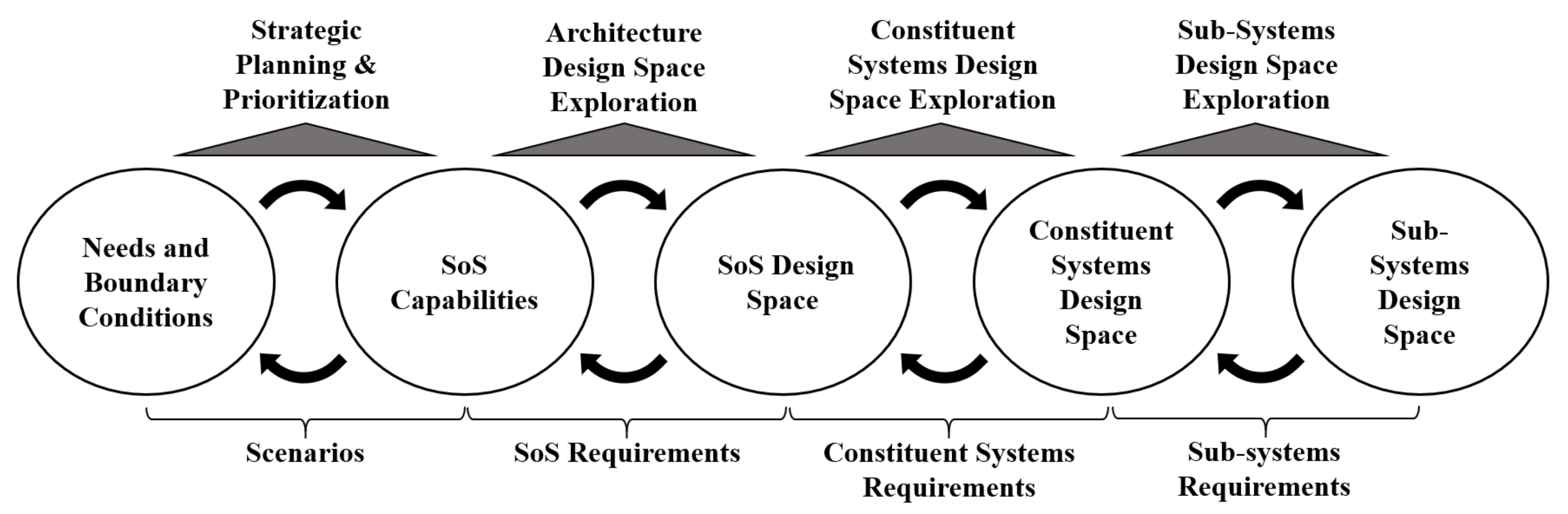
SoSs are all around us and are becoming increasingly common as digitalization enables an increasing number of systems to interoperate, share information and exchange data with each other. Suggestions for how SoS perspectives can be used in aerospace product development have been presented in related research [5]. The design process is here explained to be divided into five different levels of interest that can be used to explore SoS holistically. These levels are presented in Figure 1.
The five levels presented in Figure 1 are associated with different design spaces that are interconnected with each other. Needs and boundary conditions generate a desire for specific capabilities that can fulfil them. The required capabilities can be achieved by individual or collaborating systems that are analysed in an SoS design space. The SoS can in turn be composed of different CSs, that are subsequently composed of various subsystems. The described process has no specific starting point and can be considered recursive. This means that a change in needs and boundary conditions will propagate and consequently influence all design spaces at the different levels. A change in the subsystem design space will therefore influence the other levels in a similar way. This view of a holistic design process is envisioned to be used to investigate the influence of changes from one level to the others with “what-if” analyses and thereby explore the available design spaces. Approaches from fields such as SE have been widely used in aerospace product development and have well established practices. However, the more holistic SoS view requires different approaches to achieve satisfactory results in an ever-changing world.

1.3. Purpose of Paper

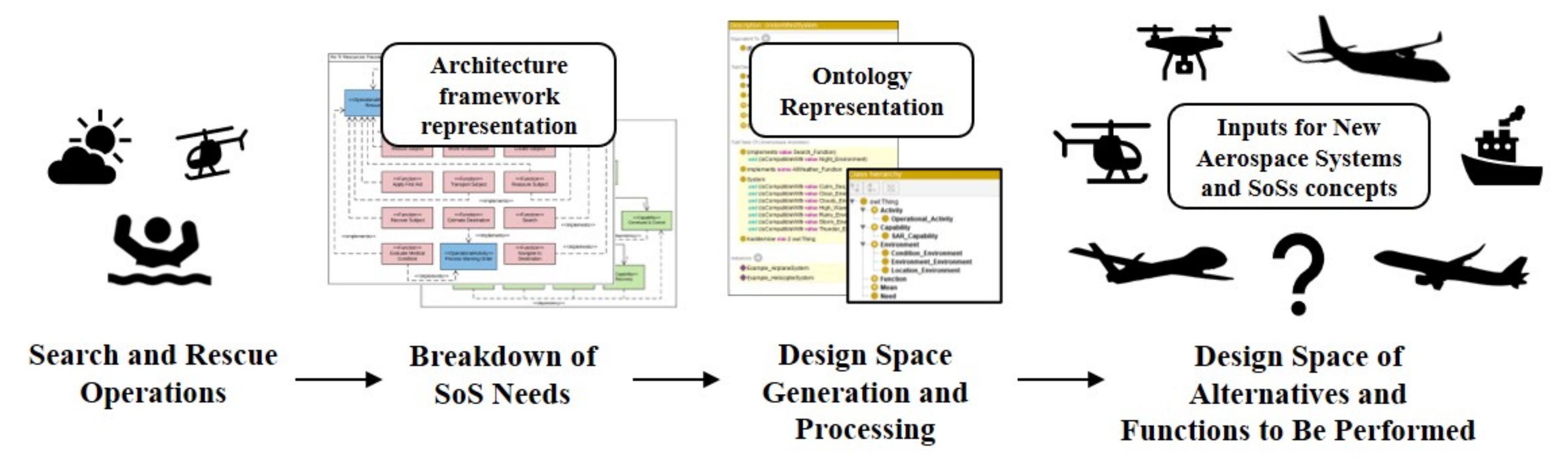
This paper presents an approach to break down SoS needs into required capabilities and functions by means of an architecture framework. The outcome of the breakdown is then represented in an ontology model that introduces the ability to dynamically investigate changes in the created knowledge representation with description logic reasoning. The ontology model also facilitates possible expansions and reductions of the captured design space representation of alternatives and functions to be performed. A case study based on the SAR operations of the Swedish Maritime Administration (SMA) and the International Aeronautical and Maritime Search and Rescue (IAMSAR) manuals is ultimately implemented to show the utility of the presented approach. The approach contributes to design space exploration methods for complex systems and SoSs and also to the realisation of the holistic design process from [5] shown in Figure 1. The overall approach and purpose of this paper is illustrated in Figure 2.
Additionally, this paper briefly describes various methods for approaching aerospace product development with an SoS view. This is shown in Section 2 together with other research results and how different research areas connect to the work presented in this paper. Section 3 describes the general workflow of the presented approach, while Section 4 illustrates the use of the approach in the SAR case study. Opportunities for future work and improvements are presented and discussed in Section 5. Section 5 also elaborates on how the outcome of presented approach can be used for a continued design process where new aerospace and SoS concepts can be generated. The most important conclusions of this study are presented at the end of the paper in Section 6.

2. State of the Art

There are many ways of approaching the complex problems related to SoS and an overall holistic perspective of a development process. Approaches that have been used in areas related to the problem outlined in the introduction are presented here. An illustration showing where the scope of the presented research is situated compared with related areas can be seen at the end of this section.

2.1. System-of-Systems and Capability Engineering

A system can be distinguished from an SoS using the five characteristic properties described in the introduction. An SoS can additionally be divided into different types, depending on its degree of centralised control. Four different types of SoS are presented in [6]. These are listed as directed, acknowledged, collaborative and virtual SoS types. They are presented in descending order of control, where the directed SoS is the type with the highest level of centralised control over the connected CS. A virtual type is typically an SoS with no central authority. An integrated air defence network is an example of a directed SoS with a high degree of centralised control over connected systems, such as airborne assets [4]. It is explained in [7] that an SoS is rarely developed from scratch. They are rather formed over time as systems interoperate to achieve new capabilities through collaboration. The process of integrating systems to achieve such capabilities is called capability engineering, which is a similar field to SoSE in many ways. As the name implies, capability engineering focuses on the capabilities of complex systems and SoSs [8]. It involves the identification and evaluation of capabilities to ensure that they are designed and sustained according to the systems’ requirements.
A common approach in SE is to use model based systems engineering (MBSE) to increase the understanding of a system and its architecture, during both development and deployment [9]. MBSE is a valued alternative to real-time and prototype testing. This is especially true in SoS applications, where the complexity and large scale introduce both economic and physical barriers to this purpose [10]. One of the commonly used approaches in MBSE is to use modelling languages such as the Unified Modelling Language (UML) or the Systems Modelling Language (SysML) to describe systems and their related properties, such as their functionality and architecture. These languages can also be used to describe important aspects of an SoS. The architecture and exchange of information between CS are examples of such aspects. Another important aspect is the emergent behaviours in an SoS. Emergent behaviour is one of the five characteristic properties described in [4] and can be defined as behaviours that only appear once systems or system elements are interacting [11]. SoS capabilities are examples of desired emergent behaviours. However, unwanted behaviours could also arise through system collaborations. MBSE is a mean by which to identify these behaviours early in the development so that they can be avoided. Desired SoS behaviours can instead be facilitated through analyses of the CS collaboration and SoS architectures.
Architecture frameworks have been developed for the purpose of describing the architecture of complex systems and SoSs [3]. Examples of such frameworks are the US Department of Defense Architecture Framework (DoDAF), the UK Ministry of Defence Architecture Framework (MoDAF) and the Unified Architecture Framework (UAF), with the latter being closely connected with UML and SysML [12]. Architecture frameworks can be used to model the complex relationships that exist in SoSs. They thereby increase the understanding of the connected systems, while also enabling analyses to ensure that they meet the intended capabilities [12]. Similar to DoDAF and MoDAF, UAF introduces a number of viewpoints that are designed to capture different stakeholders’ areas of interest. Unlike DoDAF and MoDAF, however, UAF is intended to be used in both the commercial and military sectors for system architecture descriptions.

2.2. Ontology and Ontological Engineering

A complement to MBSE is to use ontology models. Ontology models have been used in SE, SoSE and capability engineering to represent relevant domain knowledge [13,14,15,16]. Additionally, an ontology model has been used to provide a knowledge representations for system decomposition and component parameters of a civil transport aircraft as shown in [17]. The use of ontologies in SE can be referred to as ontology based systems engineering (OBSE), and a detailed state-of-the-art review of OBSE can be found in [18]. The work presented in [18] also includes a summary of possible contributions of ontologies to SE.
An ontology can be described as a formal and explicit representation of a given domain that involves knowledge of the included entities and the relationships that exists between them [19]. The field of ontological engineering includes descriptions of languages, methods and principles that can be used to create ontology models. Ontologies can be implemented in different ontology languages, where the most commonly used languages are the Resource Description Framework (RDF) and the Web Ontology Language (OWL) [20]. Web Ontology Language Description Logics (OWL-DL) is a subset of OWL that features description logic reasoning capabilities. Description logic reasoning, or simply reasoning, can check an ontology for inconsistencies but can also infer complex relationships from simpler ones [21]. Ontology and reasoning can be a way of understanding the emergent behaviours of a complex system or SoS, as explained in [15,22].
Ontologies can be seen as complements to modelling languages such as UML and SysML. However, ontologies feature an increased interoperability and scalability due to their ability to describe a domain from different terminologies and viewpoints [16]. Mappings between ontologies and SysML have been performed to enable reasoning over the represented content, improve flexibility and organise different domains to enhance information exchange [23,24]. UML and SysML models can also be used to automatically generate an ontology, as shown in [25]. Here, a case study is used to show how a SysML Requirement Diagram can be changed into an OWL ontology file to enable a better understanding of the semantic context. Ontologies made in OWL work under the open world assumption, which implies that no conclusion can be drawn about incomplete data; there can always be more information that is simply not yet known [20]. Ontologies feature the nonunique naming assumption and entities can be referred to by different names by different organisations and people. The open world assumption and the nonunique naming assumption are reasons why ontologies have increased interoperability and scalability compared to, e.g., relational databases. The interoperability aspect can be further increased by utilising a top- and domain-level ontology structure [26]. Different domain ontologies can be introduced and organised under a domain neutral top-level ontology. This enhances the interoperability and reusability between ontologies developed by different organisations. Top-level ontologies also support the creation of new and reusable ontologies that can be joined with existing ones [27]. There are many examples of different top-level ontologies, also commonly referred to as upper-level ontologies. Some of these are presented in [28] together with comparisons between them.

2.3. Design Space Exploration for System-of-Systems and Other Considerations

In SE, design space explorations are performed to find feasible solutions in a design space of alternatives [29]. The size of the available design space can be reduced by ruling out areas where intended requirements cannot be met. Explorations of a design space can also enhance the understanding of a system during early development. This can, for example, be done by investigating how changes in requirements influence the system. Many traditional SE approaches for design space explorations and product development are still applicable in an SoSE context. A function-means tree (F/M tree) is a method used for functional breakdowns and concept generations [30]. As the name implies, an F/M tree consists of functions and means, where the top of the tree describes the main functions to be performed by the system. The next level describes the alternatives of means that can perform the main functions. Each mean can be composed of lower-level functions that in turn are performed by alternative lower-level means and so on. In aircraft design, the main functions of an F/M tree can, for example, describe functions for generating lift and providing control. The corresponding means for implementing these functions can consequently include usage of a fixed wing for generating lift and control surfaces such as ailerons for providing lateral control, for example. An F/M tree creates a hierarchical structure of functions and means that can be used to generate different concepts to fulfil functions. Matrix-based approaches for representing relationships between means and functions can generate available design spaces using morphological matrices. An Interactive Reconfigurable Matrix of Alternatives (IRMA) can be used for design space refinement and allows designers to see interrelationships between concept options [29]. A general problem with matrix-based approaches is, however, that the available combinations of solutions grow at an exponential rate. This is especially true for the large design spaces available for an SoS. A design space can be represented in an ontology as shown in [31]. Ontology has here been used to represent and prune a design space for cyberphysical systems and air vehicles in a conceptual design context. The knowledge of a design space represented in an ontology can be used to create an IRMA to visualise and explore the available design space in an intuitive way. This is shown in [32] where design space refinements are performed to generate missile system concepts.
The emergent behaviours that can arise depending on the options considered in design space explorations are important to understand. Emergent behaviour exists in both systems and SoSs. It is argued in [11] that these behaviours are foreseen and appropriately tested during development in SE, while emergent behaviours in SoSs are deliberately not foreseen. The reason for this is that an SoS must be rich in emergent behaviours to achieve a broad range of capabilities. All emergent behaviours cannot be deliberately designed in. Various approaches for understanding emergent behaviours have shown that different kinds of simulations can be used for this purpose. System dynamics can be used to investigate and increase the understanding of systems through simulations [2]. It can also be used to indicate how desired emergent behaviours can be achieved in SoSs. Emergent behaviours of systems are important to understand in SoSE development, in order to predict unforeseen and undesired behaviours. Complex emergent behaviours of SoS can be produced and analysed with agent-based simulations (ABS). Consequently, ABS can be used to increase the understanding of the dynamics in SoS during the early stages of system design [33]. ABS has for example been used to evaluate performances of SoSs with unmanned aerial vehicles at a conceptual design stage as shown in [34,35].
There are many other approaches that have been used or that have shown promising results for usage, in design space exploration for SoS and aerospace applications [5]. Visual analytics, for example, is an area that give users and decision-makers a perception of data and analyses through visualisations that support human reasoning [36]. Consequently, visual analytics could facilitate the understanding of an available design space and how it is affected by certain design choices. Combined with what-if analyses, visual analytics can help increase the understanding of a design space and illustrate trade-offs between requirements and different performance measures.
The approaches that have been mentioned in this section can be used in the modelling and usage of an SoS perspective in aerospace applications. The scope of this paper and its presented research is consequently positioned between the areas illustrated in Figure 3.

3. Approach and Methods

This section presents a method that has been developed to approach the problem outlined in the introduction. It shows how the holistic view in Figure 1, and its correlated levels of interest in needs and SoS capabilities, can be approached using an architecture framework and an ontology with description logic reasoning capabilities. Parts of the approach build upon previous research results presented in [37,38].
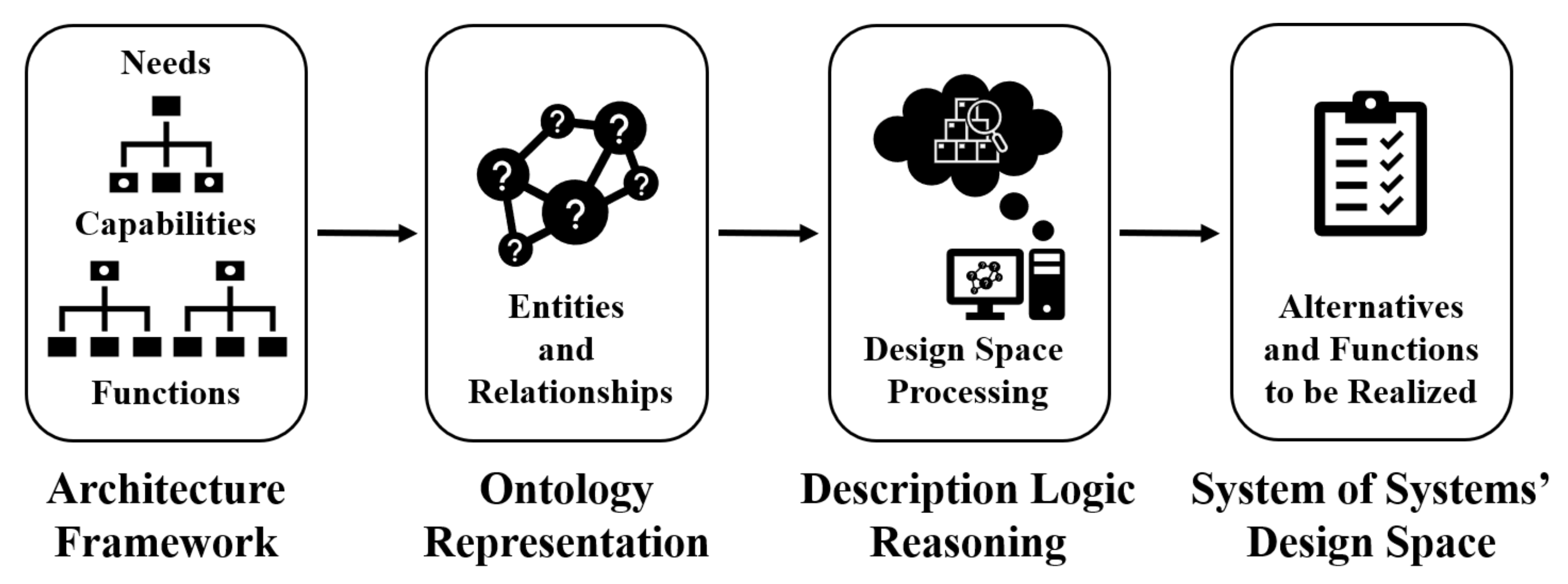
The purpose of the presented method is to illustrate how SoS needs can be broken down into capabilities using an architecture framework. The architecture framework can then be used to further break down the required capabilities into functions that must be performed by the involved systems of the SoS to meet the overarching capabilities. The use of an architecture framework provides a consistent and standard way of performing the breakdown chain described above. An ontology representation of the knowledge captured in the breakdown allows the available design space of SoS capabilities and functions to be queried and processed by a description logic reasoner. The transition into an ontology also adds a new level of flexibility for introducing changes and for adding additional information to the represented knowledge. This means that the design space can be both expanded and reduced in an efficient and traceable way using the reasoner. A reduced design space of alternatives, and functions to be performed based on user-defined needs and requirements, can thereby automatically be inferred by the reasoner. The outcome of the approach can consequently be used as inputs for a continued design process where realisations to the indicated functions can be provided by different concepts, such as aerospace systems.
An illustration of the presented approach is shown in Figure 4. The remainder of this section gives a detailed description of each part of the presented approach, while Section 4 shows how the approach can be utilised in a case study.

3.1. Breakdown of System of Systems Needs Using an Architecture Framework

The first step in the approach presented in Figure 4 is to break down SoS needs into corresponding capabilities and functions. The needs of an SoS typically correspond to those of the involved stakeholders and any customers. Architecture frameworks such as the DoDAF and UAF consist of different viewpoints designed to help in the description of architectures for complex systems. They provide a standard way to represent architectures through an MBSE approach [39]. Architecture framework viewpoints describe models for areas of interest, such as capability taxonomies, resources, standards and requirements. The intention of the presented approach is to use the taxonomy and descriptions of architecture framework viewpoints to provide a consistent way of understanding the hierarchical structure and relationships between needs, capabilities and functions.
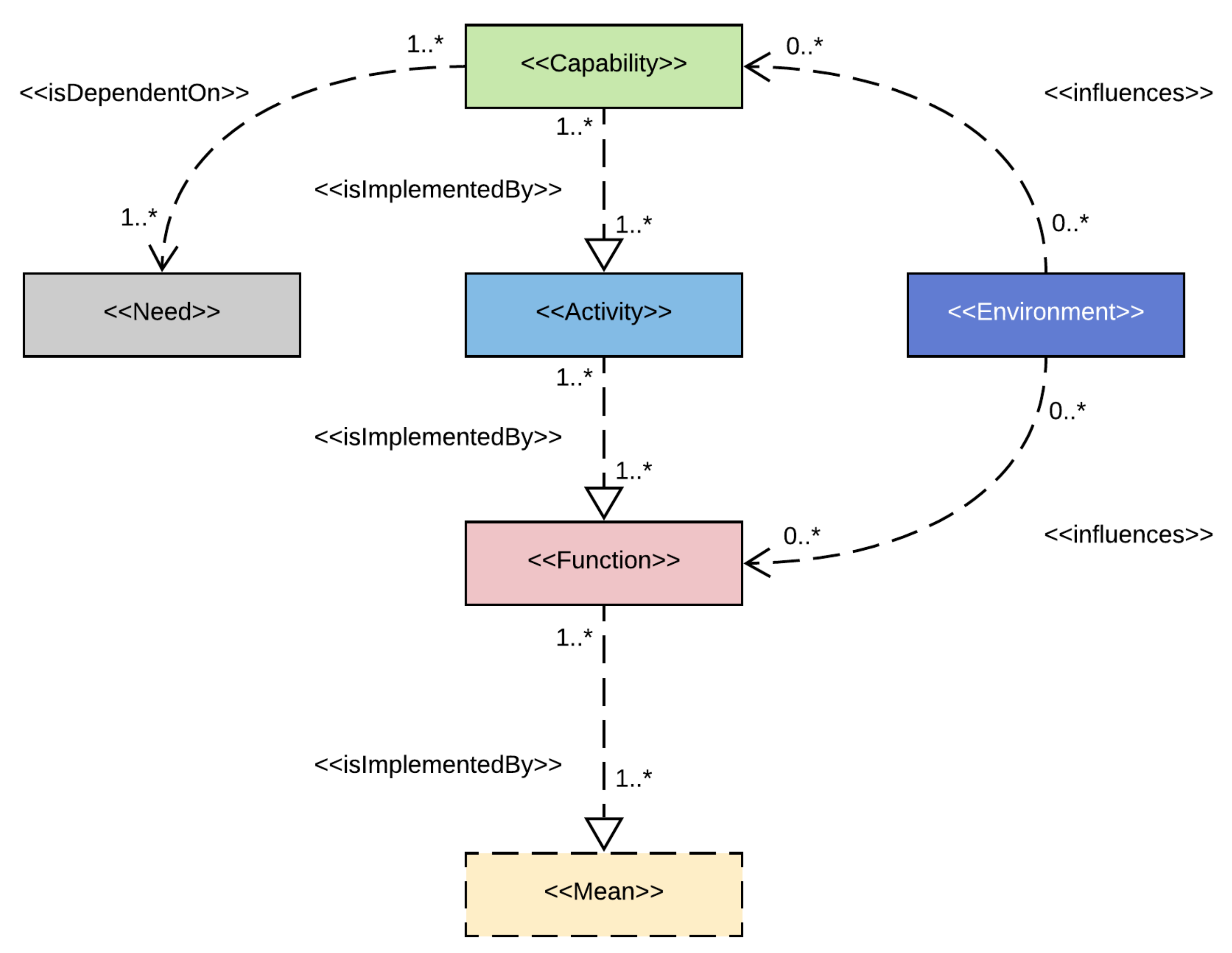
A stakeholder’s need is a request for a solution to a problem that can be provided by a service in a defined environment. In this sense, a stakeholder is an individual or organisation that has an interest in at least one phase of an enterprise described in an architecture framework. The enterprise must be capable of satisfying the stakeholder’s needs and delivering the service, which means that it must possess the capabilities of doing so. A capability is defined as the ability to perform a set of activities through a combination of ways and means. Consequently, an activity is a realisation, or implementation, of a capability through a combination of one or more functions. Functions are performed by means or elements of the enterprise in question, for example, systems and subsystems. Depending on the surrounding conditions, such as the environment, an activity might require different functions to meet the intended capability. The definitions listed above are based on the UAF documentation found in [40].
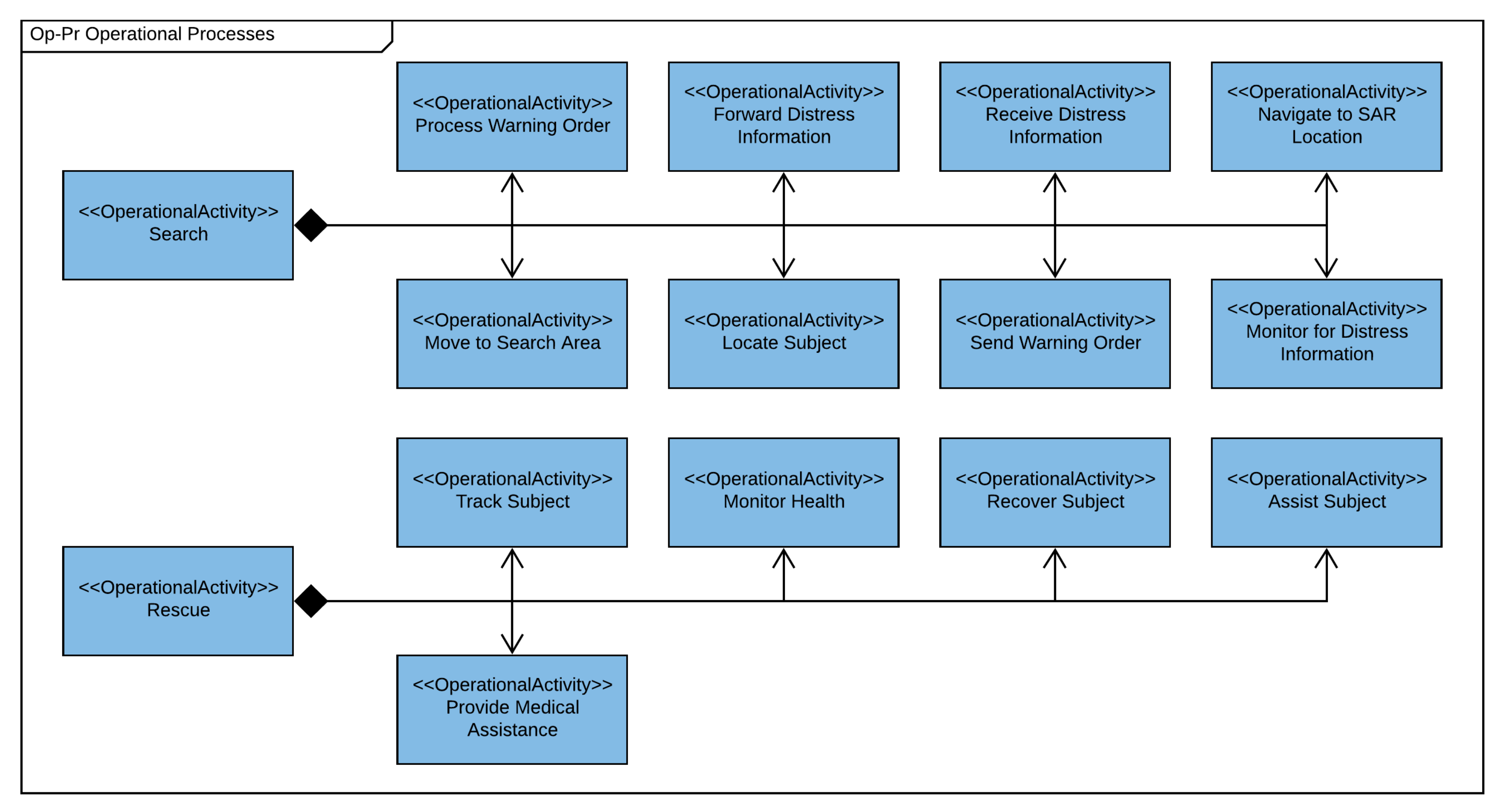
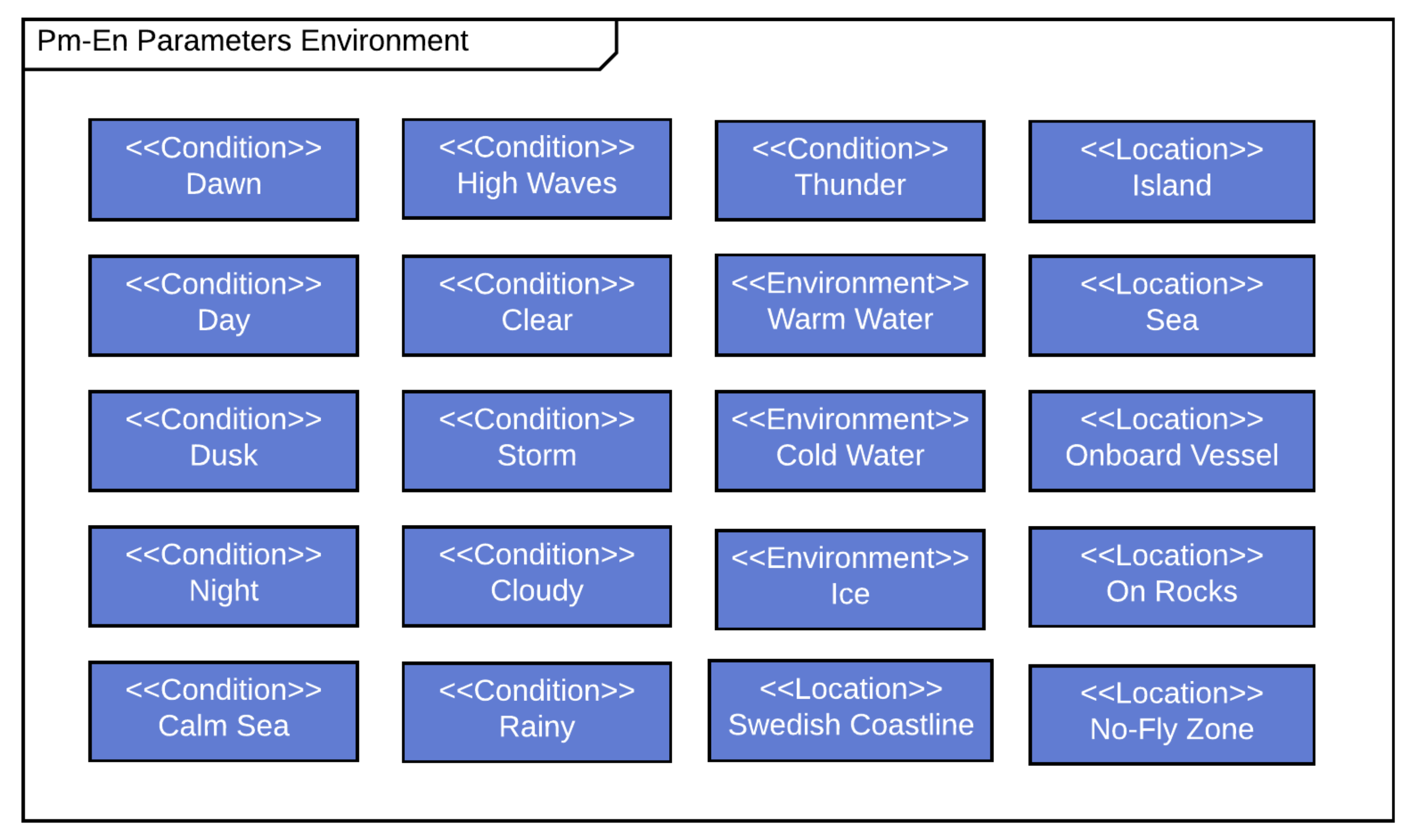
Another important aspect of architecture frameworks is the scenarios that a complex system or SoS are presumed or expected to participate in. Different scenarios will have different stakeholders and needs, which consequently lead to different capabilities and functions to be performed. Investigations of different possible scenarios can facilitate the identification of reoccurring capabilities and functions that are important to fulfil. External factors such as the environment and environmental conditions of a scenario must also be considered. As stated in the introduction, changes in the outside world will influence the required capabilities. It is therefore important to ensure that the capabilities and functions can be sufficiently performed over time and under changing external factors.
Architecture frameworks include many more considerations and viewpoints than those described in this section. However, the purpose of the approach is to identify functions that are to be performed by constituent systems of an SoS. Consequently, the architecture framework is mainly used as a structured, standard and consistent way of performing the breakdown as mentioned previously. In addition, the architecture framework viewpoints give an indication of what needs to be included and modelled to capture the holistic view of an SoS. Figure 5 shows an illustration of the intended architecture framework breakdown approach.
As illustrated in 
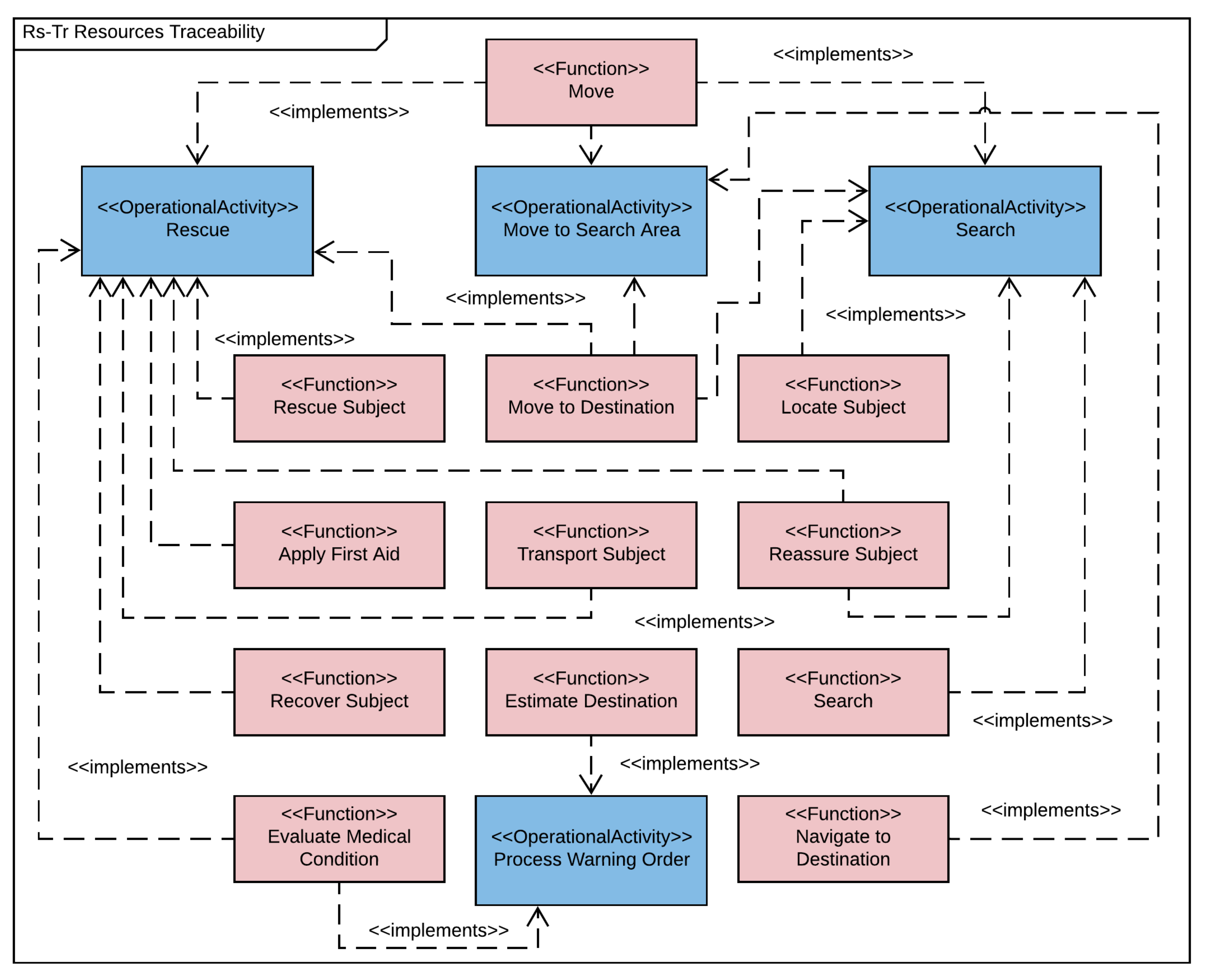
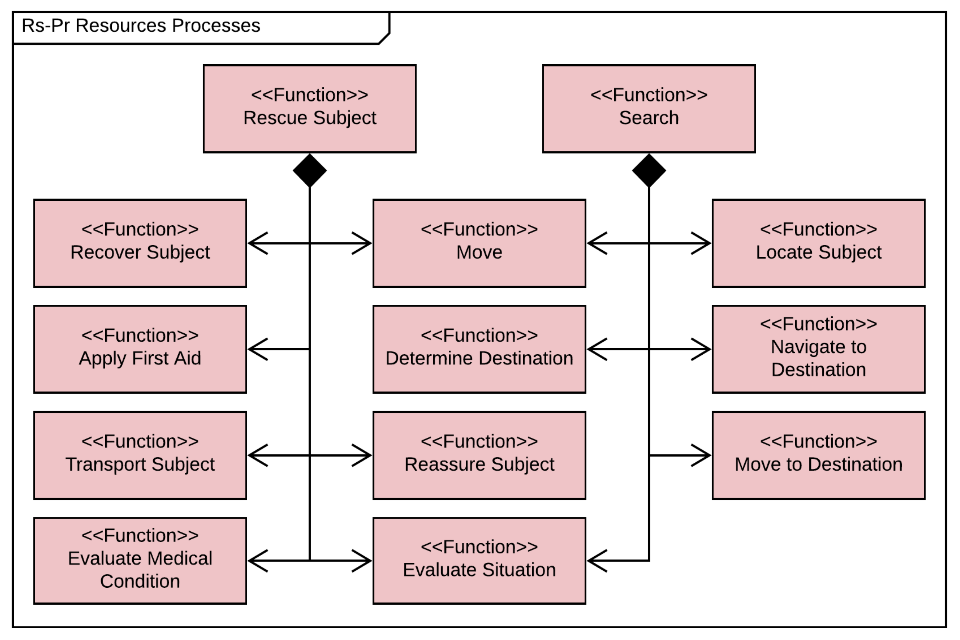
Figure 5, needs must always be associated with capabilities to be fulfilled. A capability is therefore dependent on a corresponding need. A capability can be implemented by at least one activity, and in a similar way one or more activities can implement at least one capability, if seen in the inverse direction. The same also applies between activities and functions. This structure is very similar to that of an F/M tree, where functions and means alternate. Therefore, capabilities can be treated as functions. This implies that they can be seen as the main functions to be performed, and activities are the means by which to implement them. The activities are implemented by functions that in turn can be allocated to suitable means, such as systems and subsystems. The F/M tree approach can thereafter be continued to perform more detailed functional breakdowns if desired. The environment can influence both capabilities and functions, as shown in Figure 5. The environmental conditions can consequently introduce constraints on a capability required to implement an activity, for example.

3.2. Ontology Representation

The next step of the approach is to represent the outcome of the architecture framework breakdown in an ontology. The modelling of the ontology can be done using an ontology development process presented in [
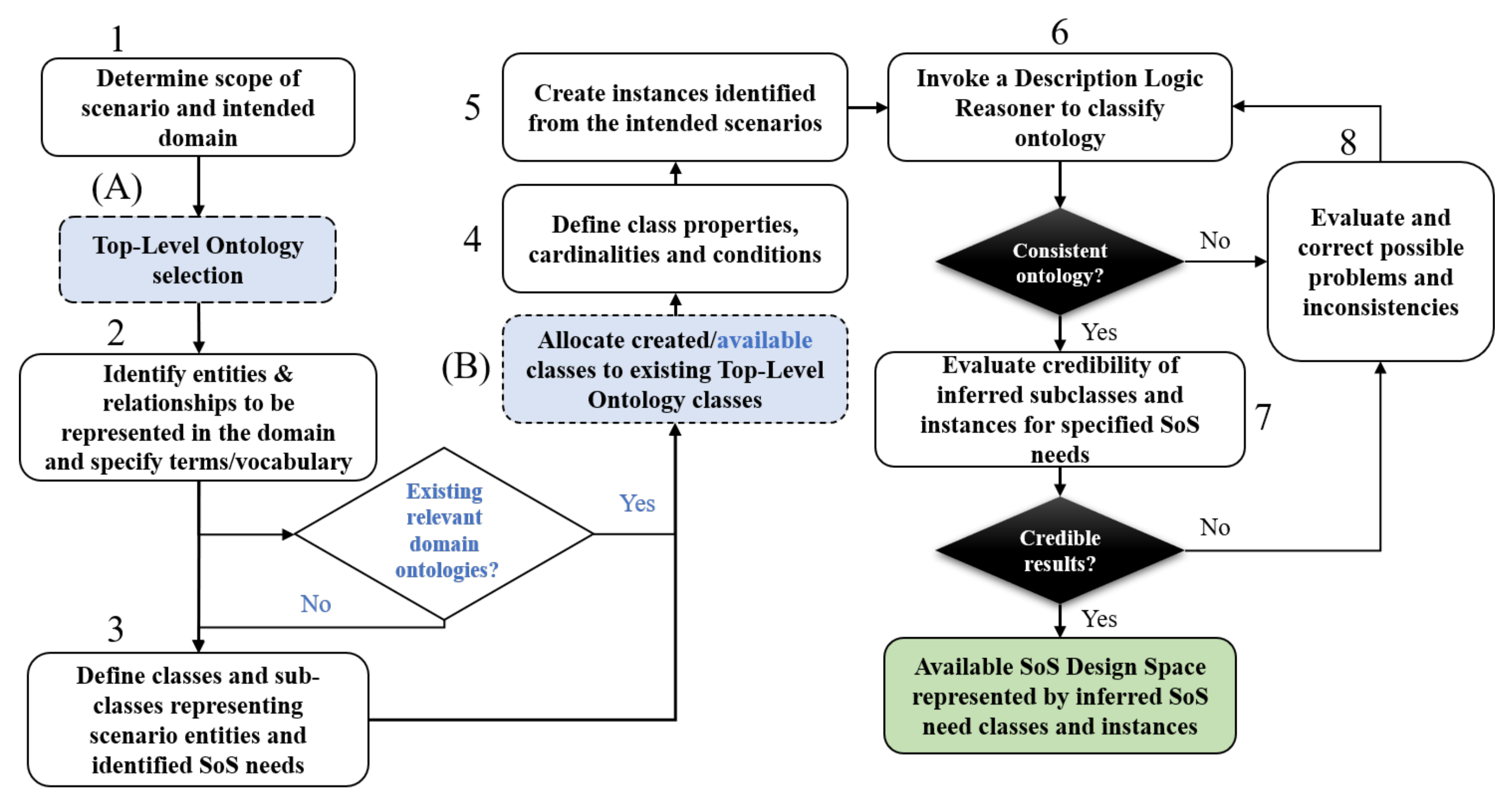
37]. The modelling is here performed through eight consecutive steps that can be used to generate and process an SoS design space. Figure 6 shows the different steps of the ontology development process.
Step 1 of the process is used to determine what should be modelled in the ontology. This corresponds to the domain and scenarios of interest that are to be represented. An optional step, denoted (A) and (B) in Figure 6, can be used if a top-level ontology structure is desired or to be used. A top-level structure can bring several benefits, as explained in Section 2.2. It is also possible to include existing relevant domain ontologies. More details on these optional steps are found in [
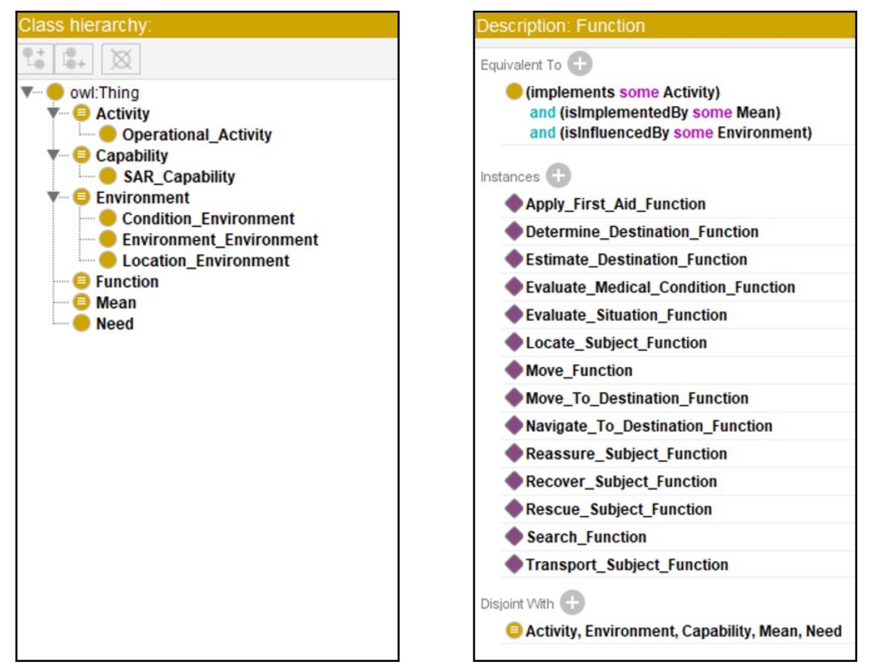
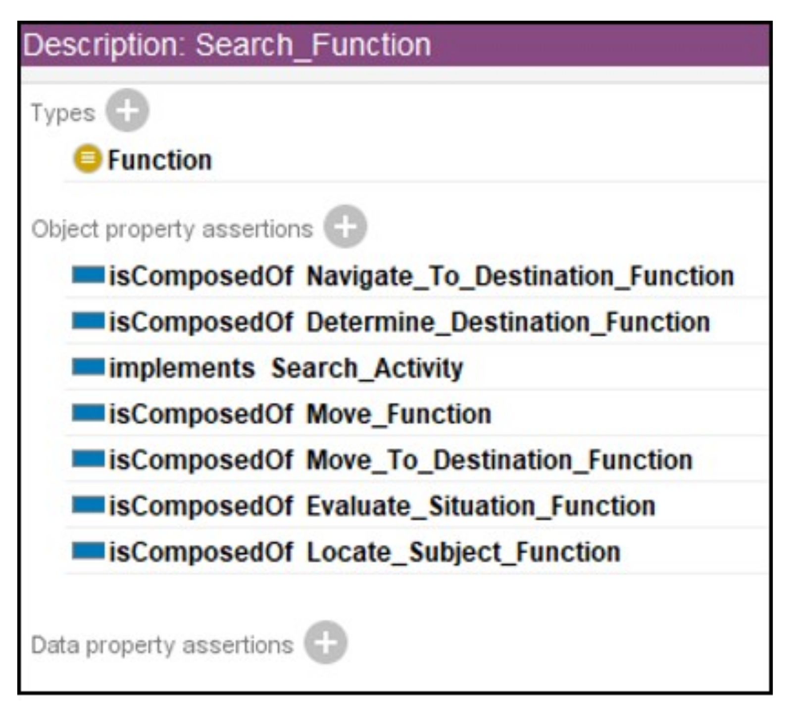
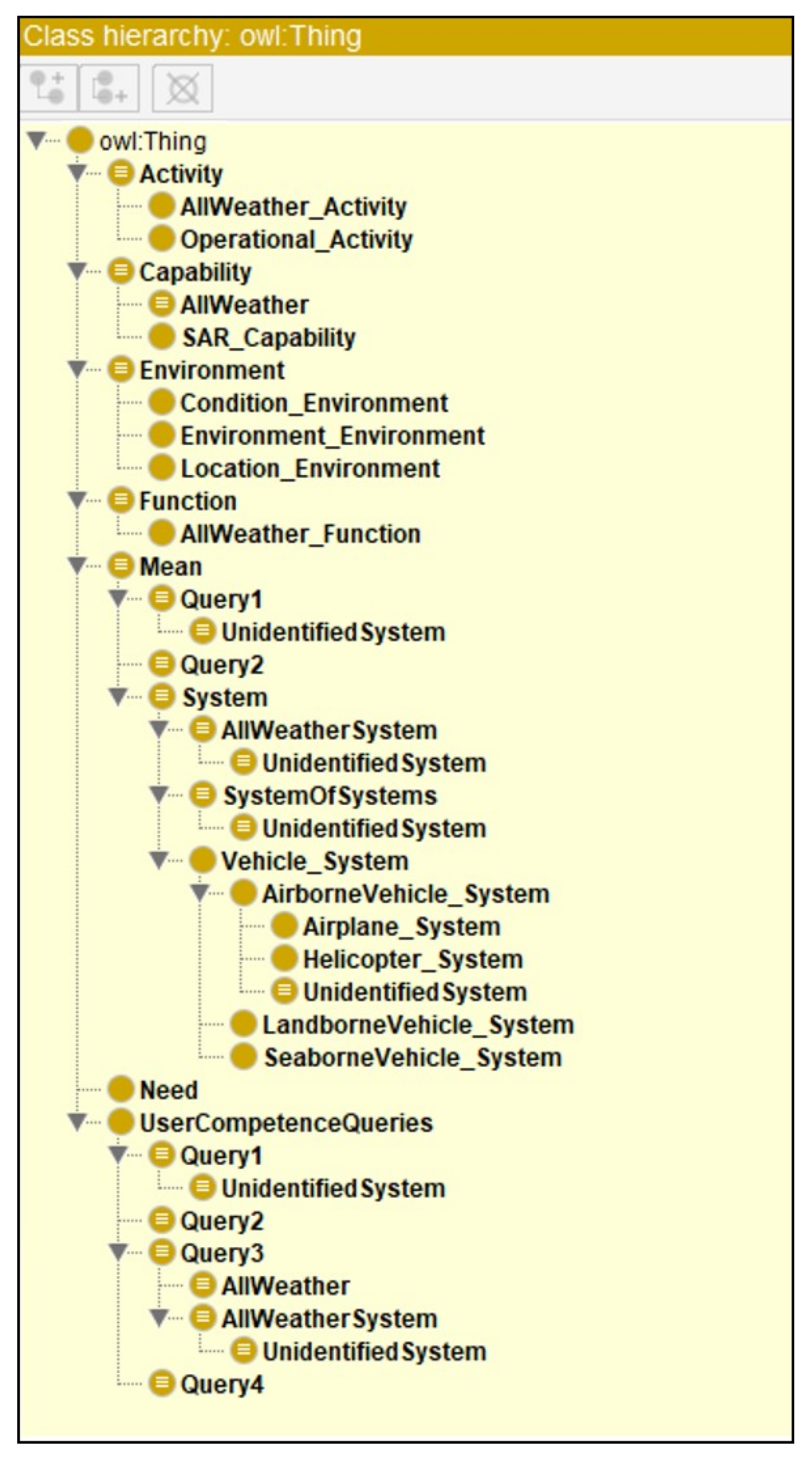
37]. The second step is to identify the entities and relationships that are to be modelled in the ontology. Entities include capabilities, functions and environmental conditions but can also be physical components such as systems or resources. In the third step, the previously identified entities are modelled in the ontology as classes in a structured taxonomy. The fourth step corresponds to the modelling of relationships that exist between classes. Instances, also called individuals, are the lowest granularity of an ontology and should represent the lowest level of the previous breakdown from the architecture framework. This can, for example, be a specific function or capability. An instance can also correspond to a certain type of aerospace system, such as a specific helicopter or airplane.
The remaining steps of the ontology modelling process involve the use of a description logic reasoner that can classify the ontology and create a design space of alternatives or functions to be performed by the SoS. The following section describes steps six to eight in more detail.

3.3. Design Space Processing with Description Logic Reasoning

As step six in 
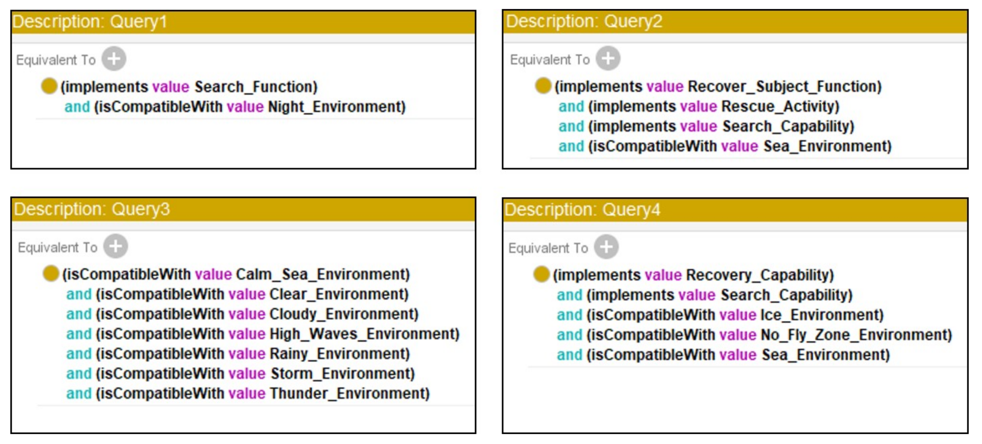
Figure 6 explains, the invocation of a reasoner is done to classify the ontology and check it for inconsistencies. The reasoner will build up a new ontology based on the modelled classes and relationships between them. This new ontology is called an inferred ontology, while the unclassified one is referred to as an asserted ontology. The knowledge represented in the ontology model can also be further expanded and processed at this stage using the reasoner. This can be done, for example, by creating defined classes that contain necessary and sufficient conditions. Defined classes can be populated with classes and instances that fulfil the specified necessary and sufficient conditions described in the defined class definition. This means that a reasoner can automatically position new information added to the knowledge base under the appropriate classes if modelled correctly. Defined classes can, in this sense, also be used to generate a reduced design space of alternatives or functions to be performed based on user-defined needs and requirements of an SoS. The reasoner can consequently populate these defined classes with the classes and individuals that are able to satisfy the described conditions in them. A design space of alternatives or functions that fulfil the defined needs and requirements can therefore be created and simultaneously reduced.
The credibility of inferences made to the defined classes should be evaluated and checked for unexpected results, as explained in [37] and step seven of the process in Figure 6. Step eight is only to be performed if inconsistencies are found or unreasonable results are achieved. The inferred design space captured in the ontology can finally be extracted and further processed or evaluated.

3.4. Design Space of Alternatives and Functions to Be Performed

Finally, the approach illustrated in Figure 4 gives a set of alternatives or functions that are to be fulfilled to satisfy desired needs and requirements. It is possible to explore the design space of alternatives or functions to be performed using the reasoner. This can be done by changing class definitions in the ontology, or by adding additional defined classes, to see how the changes propagate due to changing scenarios and circumstances, for example. The reasoner can reinfer the asserted ontology and thereby show how the sets of alternatives or functions to be performed have changed. The alternatives and functions that are most persistent to changes can consequently be identified as the ones that are most important for the SoS to fulfil in order to cover a wide range of possible scenarios. These “what-if” investigations can also be performed on the environmental conditions to get a perception of their influences on the design space.
The resulting reduced design space of alternatives can be further investigated using ABS, for example as shown in [38], where the performance measures of different SoSs with airborne SAR assets are investigated. The subsequent realization of the reduced design space of possible functions to be performed can be investigated with a continued F/M tree approach, as mentioned previously. However, the scope of this paper is mainly to show how a reduced design space of alternatives or functions to be performed can be obtained, and a further evaluation and realisation part is therefore not covered. Section 5 discusses this in more detail and provides examples of possible next and additional steps of the presented approach, together with brief elaborations on them.

4. Search and Rescue Case Study

The implementation of a search and rescue (SAR) case study based on the operations of the Swedish Maritime Administration (SMA) is carried out to test the approach presented in Section 3. The case study shows how the Unified Architecture Framework (UAF) can be used to perform the breakdown and how an ontology model can be used to further process the outcome. SAR operations can be considered as SoS with typically high degrees of centralised control that often include several types of aerospace systems, such as rescue helicopters and search airplanes. SAR is also an area where changes in the operational environment, such as weather conditions, can introduce large changes in required capabilities and functions. The aim of the case study is not to create a full representation of SAR with either architecture frameworks or ontology. Overall, the breakdown is kept at a basic level to illustrate the intended usage of the presented approach.

4.1. Breakdown of Needs

The needs of an SAR must be understood in order to break them down into corresponding capabilities and functions. The goals and ambitions of the SAR operations performed by the SMA are described in [41,42], together with their objectives and resources. This case study builds on the information from these sources together with the SAR system concept and overview available in the IAMSAR manuals [43,44,45]. A UAF sample problem, available from [46], was used as both a source of inspiration and a guideline for utilising the UAF in the presented case study.
The IAMSAR manual [43] describes that any SAR system should be able to fulfil the four basic needs listed below. These four needs are the starting point for the breakdown illustrated in this case study.
  • To “receive, acknowledge, and relay notifications of distress from alerting posts”
    (i.e., manage information).
  • To “coordinate search response”.
  • To “coordinate rescue response and delivery of survivors to a place of safety”.
  • To “provide medical advice, initial medical assistance or medical evacuation”
    (i.e., provide assistance).
With the established basic needs of any SAR, the breakdown into capabilities can begin. The SoS must be capable of meeting these needs, and there must consequently be a capability for coordinating search responses, for example. A capability can be subdivided into a number of lower-level capabilities. A capability connectivity described in the Strategic Structure (St-Sr) view of the UAF is used for this purpose. UML composition, generalisation and dependency relationships are here used to describe the capability connectivity. An illustration of the breakdown into lower-level capabilities for an overarching SAR capability, which meet the needs specified above, can be seen in Figure 7.
As Figure 7 shows, the top capability in the hierarchy is the capability to perform SAR. This capability can be further subdivided into maritime and land-based SAR. An SAR system must have the ability to coordinate both a search and a rescue response as well as being able to monitor a distress signal and provide command and control. The coordinate search and coordinate rescue response capabilities consists of lower-level capabilities that must be met. The command and control capability is central in SAR operations and consequently has many dependencies with other capabilities in the SAR system. All capabilities of the SAR system—without relationships—can be listed in the Strategic Taxonomy (St-Tx) view of the UAF.
A capability is realised once an activity that utilises that capability takes place. During an activity, a number of functions are performed to achieve the desired capabilities together. All related functions are not necessarily performed during an activity. The operational environment and conditions have a significant influence on the functions required to meet the capabilities. For example, search activities at night require functions for seeing in the dark. The breakdown of relationships between capabilities and operational activities is illustrated using the Operational (Op) domain of UAF together with its Traceability (Tr) model. Figure 8 shows this Operational Traceability (Op-Tr) view for the relationships between lower-level capabilities and operational activities.
An activity can consist of several lower-level activities. The Operational Processes (Op-Pr) view of the UAF is used to break down and illustrate the hierarchy of operational activities. A breakdown of the search and rescue operational activities is illustrated in Figure 9.
SAR operations consist of different activities that take place during an SAR mission. As Figure 9 shows, a rescue activity involves tracking the subject to be rescued as well as providing first aid if required and of course the recovery and assistance of the rescue subject. An activity can be implemented by one or more functions. The Resource Traceability (Rs-Tr) view of the UAF is designed to capture the traceability and mapping between the activities and functions that implement them. Figure 10 shows how the Rs-Tr view can be used for a few selected activities. Similar to the capabilities, all expected activities—without their relationships—can be listed in the Operational Taxonomy (Op-Tx) of the UAF.
Functions can be broken down into lower-level functions similar to capabilities and activities. An example of a functional breakdown can be seen in Figure 11, which shows the Resources Processes (Rs-Pr) view of the UAF. The Rs-Pr view can be used to show the hierarchy of functions that are to be performed in activities that realise the capabilities of the SAR system.
As Figure 11 shows, the function of rescuing a subject in distress involves several subfunctions. The rescue function is consequently built up of functions to provide movement, evaluate the medical conditions of the rescue subjects, transport the subjects off the scene, etc. A listing of all functions for the SAR system—without their relationships—can be represented using the Resources Taxonomy (Rs-Tx) view of the UAF.
Important considerations during all activities include the operational environment and the surrounding circumstances. In maritime SAR, weather conditions have a significant influence on which functions are needed to perform an activity, as previously mentioned. The location of a subject to be rescued can also impose certain restrictions on the SAR system. The rescue subject could, for example, be situated in a no-fly zone that will impose restrictions on the realisations for the “navigate and move to destination” functions. Environmental conditions such as water temperature will introduce time restrictions and required performances to realise the rescue activity in time. The environmental conditions that the SAR system is considered to operate in can be represented and visualised using the Parameters Environment (Pm-En) view of the UAF. Figure 12 shows an example of this.
The views that have been illustrated in this section are just a few parts of the UAF, and more details of SAR operations can be included if so desired. As previously mentioned, the intention of this case study is to show how the UAF can support the breakdown of SoS needs into capabilities, activities and functions. The following sections describe how the process shown in Figure 6 can be used to represent and also expand the knowledge captured from the various UAF views.

4.2. Ontology Modelling and Reasoner Usage

The information and knowledge captured in the UAF breakdown can be automatically classified and used to gain a higher understanding of the content, by being represented in an ontology with description logic reasoning capabilities. The implementation in an ontology allows a reasoner to automatically handle the complex relationships that were created with the UAF. Thereby, a reasoner also allows the captured knowledge to be queried and navigated in a flexible way. The ontology modelling is done in the Protégé ontology editing software [47], with the process described in Figure 6. Additionally, Protégé’s Pellet reasoner is used throughout the case study.
The first two steps of the process in Figure 6 have already been carried out with the UAF breakdown. The scope and domain are consequently a representation of the outcome of the breakdown, and entities correspond to, e.g., capabilities, activities, functions and environmental aspects of SAR. The optional steps of including existing ontologies and a top-level ontology structure were excluded from this case study to better show the modelling of the architecture framework outcomes.
The structure shown in Figure 5 is implemented in the ontology according to steps 3 and 4 of the process from Figure 6. This is done to represent the general structure between the entities from the UAF breakdown as classes and their relationships. Figure 13 shows the ontology’s class hierarchy and the definition of the Function class, with its relationships to other classes.
The Function class shown to the right in Figure 13 is here specified as a Defined class. Consequently, the class contains necessary and sufficient conditions stating that anything that can implement an activity, is implemented by a mean and is influenced by the environment must be a function (or equivalent to a function). A reasoner can thereby automatically classify a newly added entity as a function if it fulfils the stated conditions.
Figure 13 also shows that the Function class is associated with individuals describing the derived functions from the UAF breakdown. The individuals in the ontology correspond to the various outcomes from the different stages of the breakdown. Figure 14 shows the definition of the Search Function individual and its relationships with other individuals, as described by the breakdown in Figure 11.
The ontology modelling up to step 6 of the process from Figure 6 results in an ontology that describes the outcome from the existing UAF breakdown. The reasoner can check the ontology for inconsistencies and evaluate whether the represented knowledge is logically valid. Another important advantage that a reasoner provides is that it can automatically handle the complex relationships between represented entities. Even though the UAF breakdown was kept at a relatively basic level, the relationships captured from it create a complex network of dependencies between entities.

4.3. Expanding the Ontology and Design Space Processing

The current ontology representation can now be expanded with, for example, available SAR assets that can be associated with the corresponding functions that they implement. The expansion of the ontology can also be based on new additional capabilities or relationships between entities. For this case study, the ontology representation is mainly expanded with a few different types of example SAR assets as well as a definition of an implicit all-weather capability and an all-weather system. The expansion also includes an example definition of an SoS and an unidentified system that implicitly describes an SoS comprised of two airborne SAR assets. The intention of the expansion and the subsequent design space processing is to let the reasoner infer implicit knowledge in the ontology representation and answer user-defined queries that give the available design space of alternatives and functions to be performed. The expanded ontology hierarchy can be seen in Figure 15, together with the definition of an example airplane system individual.
The added subclasses under the Mean class contain definitions for different systems and an SoS as seen in Figure 15. The definition of the Example_AirplaneSystem individual shows how it implements some of the derived SAR functions, and how it is related to the environmental conditions through the isCompatibleWith and isNotCompatibleWith properties. The Example_AirplaneSystem individual is compatible with most of the environmental conditions from the previous breakdown. It is however defined as incompatible with the No_Fly_Zone_Environment individual, which restricts airborne vehicles. The Example_AirplaneSystem is also implementing the search and move to destination functions for example. However, it is not related to the recover subject function as this requires other means, such as an example helicopter or seaborne system. The expanded ontology hierarchy in Figure 15 also contains a class for the implicit all-weather capability. The definition of this class and the SoS class are shown in Figure 16.
Here, the definition of the AllWeather class is not explicitly saying that it is a capability, and one of the reasoner’s tasks is consequently to classify it as a subclass of the Capability class. Reasoning can also infer the available SAR assets that can meet the conditions for implementing an all-weather capability. The AllWeatherSystem class, in the class hierarchy from Figure 15, is an example of such a class that the reasoner can populate with the suitable SAR assets. SAR helicopters can be examples of systems with all-weather capabilities, as explained in [41].
The System Of Systems class contains a definition describing anything that has more than two members and is regarded as belonging to the Mean class. The previously mentioned unidentified system is added as an “UnidentifiedSystem” class to the expanded ontology as an example for the reasoner to classify as an SoS. The class definition contains “hasMember” properties to the Example_HelicopterSystem and the Example_AirplaneSystem.
Finally, the UserCompetenceQueries class, which can be seen in the hierarchy in Figure 15, contains several defined classes that are used to query the ontology for the individuals and classes that have the necessary and sufficient conditions to be regarded as members of the class. These classes can consequently be used to create a reduced design space of alternatives or functions to be performed based on user-defined queries, asking for specific needs, performances or requirements, for example. Additionally, the defined classes can also be used to only ask for the options that are regarded as airborne vehicle systems if desired. Such a reduced design space will consequently only include alternatives capable of flying. Figure 17 shows the definitions for the four example queries in this case study.
At this stage, the reasoner can be reinvoked to classify and build up the inferred ontology once again. Figure 18 shows the difference for the UnidentifiedSystem class before and after reasoning.
The UnidentifiedSystem class has gained more information for its definition after reasoning, as seen in Figure 18. It has been correctly inferred to be a subclass of the SystemOfSystems class, since it includes more than one hasMember property. It has also been classified as an airborne vehicle system, since it only includes airborne SAR assets. Furthermore, both Query 1 and AllWeatherSystem are inferred as superclasses. This means that the UnidentifiedSystem class fulfils the conditions to be regarded as a solution to query 1 as well as an all-weather capable system. This is further explained in the text related to Figure 19 and Figure 20.
The available design space of alternatives, or functions to be performed, is represented by the inferred subclasses and individuals of the different query classes. Figure 19 shows the definitions for example queries one and two, with the inferences made by the reasoner.
As Figure 19 shows, the Query1 class can be fulfilled by two of the example system individuals represented in the ontology. However, the UnidentifiedSystem class was inferred to be a subclass of Query 1, which means that its individuals also fulfil the described conditions. The Query1 class is consequently fulfilled by all the example system individuals represented in the ontology. The reasoner can also automatically classify the Query1 class as a mean, since it implements at least one function. The Query2 class is only fulfilled by the example helicopter and seaborne system, since they both implicitly possess a search capability and are able to perform a rescue activity by recovering a subject at sea. The performance between the two might however differ. The helicopter in query 2 can, for example, be able to cover a larger search area but at a higher cost per hour than the seaborne system. It is also possible that the conditions can be fulfilled from an SoS perspective. The example helicopter could for example provide the search function while the seaborne system provides the rescue activity. Another possibility is that the conditions can be fulfilled by an SoS with only helicopter systems. The different helicopters can in this case fulfil different roles. For example, one helicopter can implement the main search capability while two other helicopters perform the rescue activity and thereby recover the subjects from the sea. The number of SAR asset types to be used, and their corresponding roles, can be further investigated with e.g., ABS. Finally, since both systems implement at least one function, the reasoner infers that Query2 is describing means here as well.
The classes for Queries 3 and 4 have no inferred instances in their definitions. Query 3 can be explained by looking at the inferred class hierarchy, which is shown in Figure 20.
Both the AllWeather and the AllWeatherSystem classes have been inferred to be subclasses of the Query3 class, as shown in Figure 20. The UnidentifiedSystem class is, as previously mentioned, an all-weather capable system and it consequently fulfils the conditions to be a solution for query 3. Additionally, both the Example_AirplaneSystem and the Example_HelicopterSystem individuals fulfil the conditions to be regarded as all-weather systems in this example. Both these individuals are therefore also valid solutions on their own to query 3. The implicit all-weather capability, or AllWeather class, fulfils the described conditions as well. This means that anything with an all-weather capability will be regarded as a solution to the query. Additionally, the AllWeather class has also been correctly placed by the reasoner as a subclass of the Capability class, as seen in Figure 20. Another thing worth mentioning is that the reasoner has inferred the SystemOfSystems class to be a subclass of System in the inferred class hierarchy. An SoS can therefore be seen as a specialisation of a system, and it consequently inherits the general system properties.
Query 4 has not been populated with any individuals or subclasses. The reason for this is that there are no available entities that fulfil the described conditions in the current ontology representation. Query 4 consequently shows that no existing SAR solution can be used. The described conditions in query 4 thereby indicate the overarching capabilities and environmental conditions that must be fulfilled by, for example, a modified existing asset or a new system to be acquired or developed. The corresponding activities and functions for each requested capability from the previous breakdown can therefore be used as inputs for an F/M tree approach to develop of a new SAR asset or system, for example. This is also further discussed in Section 5.
The ontology representation that has been used in this case study is available from [48], together with the diagrams describing the UAF breakdown in this section.

5. Discussion and Future Directions

The case study presented in the previous chapter has shown how the suggested approach in this paper can be used to help breakdown SoS needs into required capabilities and functions. The case study has also shown how the reasoning capabilities of an ontology made in OWL can be utilised to expand the captured knowledge and to increase the understanding of the available design space of alternatives and functions to be performed by new aerospace systems and SoS concepts. Consequently, the presented work has covered and contributed to the realization of all levels of interest in Figure 1, except for the subsystem design space level. The outcome of the approach is intended to be used in conceptual design of new aerospace systems. However, the approach is kept general as derived functions also can be fulfilled by SoSs including nonairborne systems as well.
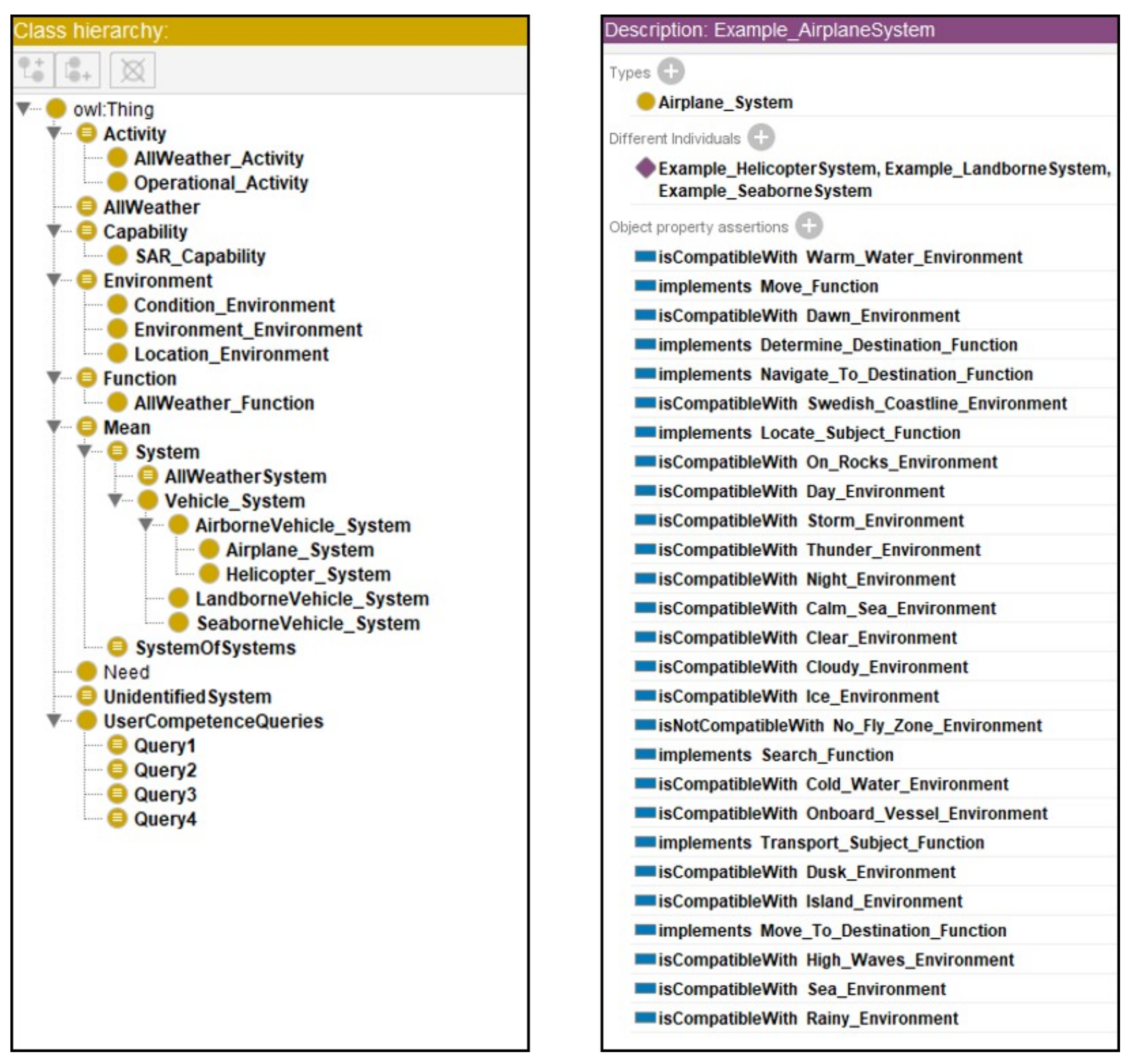
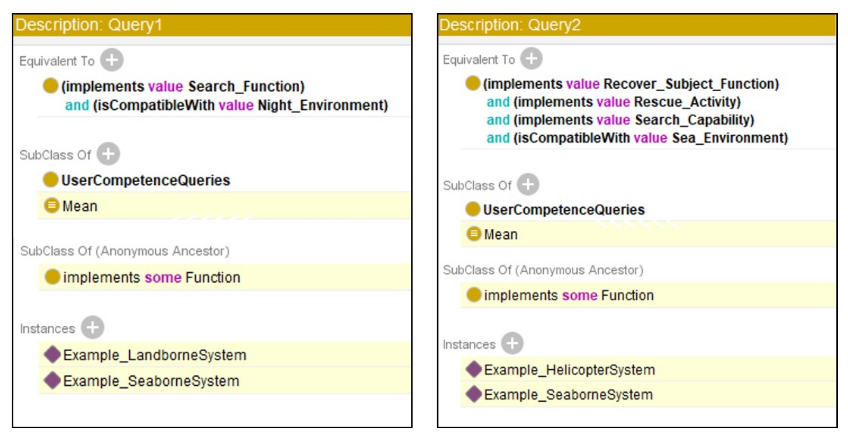
As the results from the user competence queries show, the available design space of alternatives is captured in the inferred suitable instances and subclasses of the different query classes. The queries both generate and reduce the available design spaces through reasoning. The descriptions for these suitable instances and subclasses could be extracted from the inferred ontology to enable further analyses with ABS, for example, as illustrated in [38]. However, this presumes that the represented instances in the ontology have the necessary information to sufficiently describe the ABS agents. Since no further evaluation of the design space was carried out in this study, the example system individuals from the ontology did not include additional information such as detection range and fuel consumption. Information like this can be added if desired by being represented in relationships to OWL data properties. Data properties can for example describe any parameter for airborne vehicles such as maximum takeoff weight, operational range, cost per hour and more. Reasoning can then be performed to also reduce a design space of existing alternatives based on requirements for specific values of parameters as shown in [37]. It is consequently possible to query the ontology and design space for all airborne vehicles that have an operational range above a certain number but with a low cost per hour for example. Queries with no inferred instances or subclasses can in this case also be regarded as inputs for a continued design process where the desired data properties correspond to system requirements.
The UAF representation of the SAR system, with its relationships between entities, is very similar to the representation in the ontology model. The reason for using both an architecture framework and an ontology in the approach is that both have their specific advantages. Architecture frameworks provide a structured way to represent information through their various views. Architecture frameworks also indicate what should be modelled and give a perception of the important aspects that must be included in a complex system or SoS. They also divide up the represented system through the various views, which facilitates the visualisation of specific entities and their relationships. Another important area of use for architecture frameworks is analyses of operations and how resources are to be utilised. The UAF breakdown was focused on arriving at the functions to be performed and not specifically on the utilisation of existing resources, such as specific airborne SAR vehicles. The approach consequently shows how the UAF can be used to support aerospace product development from an SoS perspective.
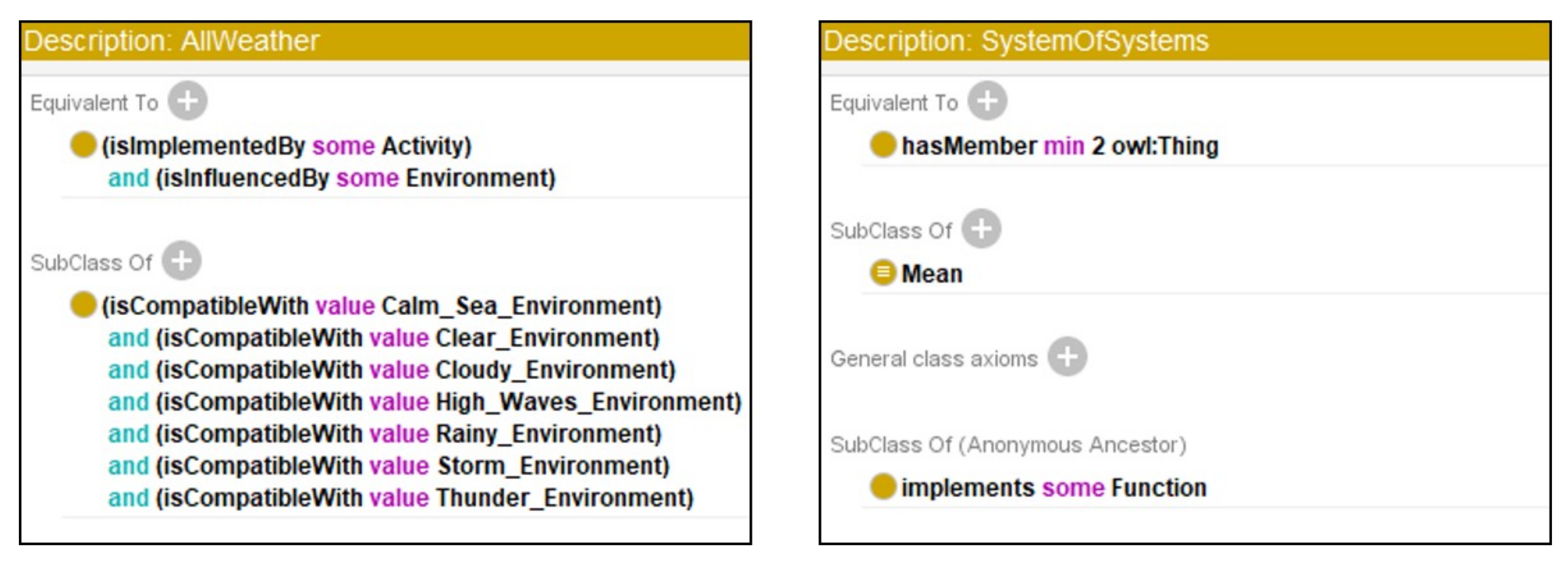
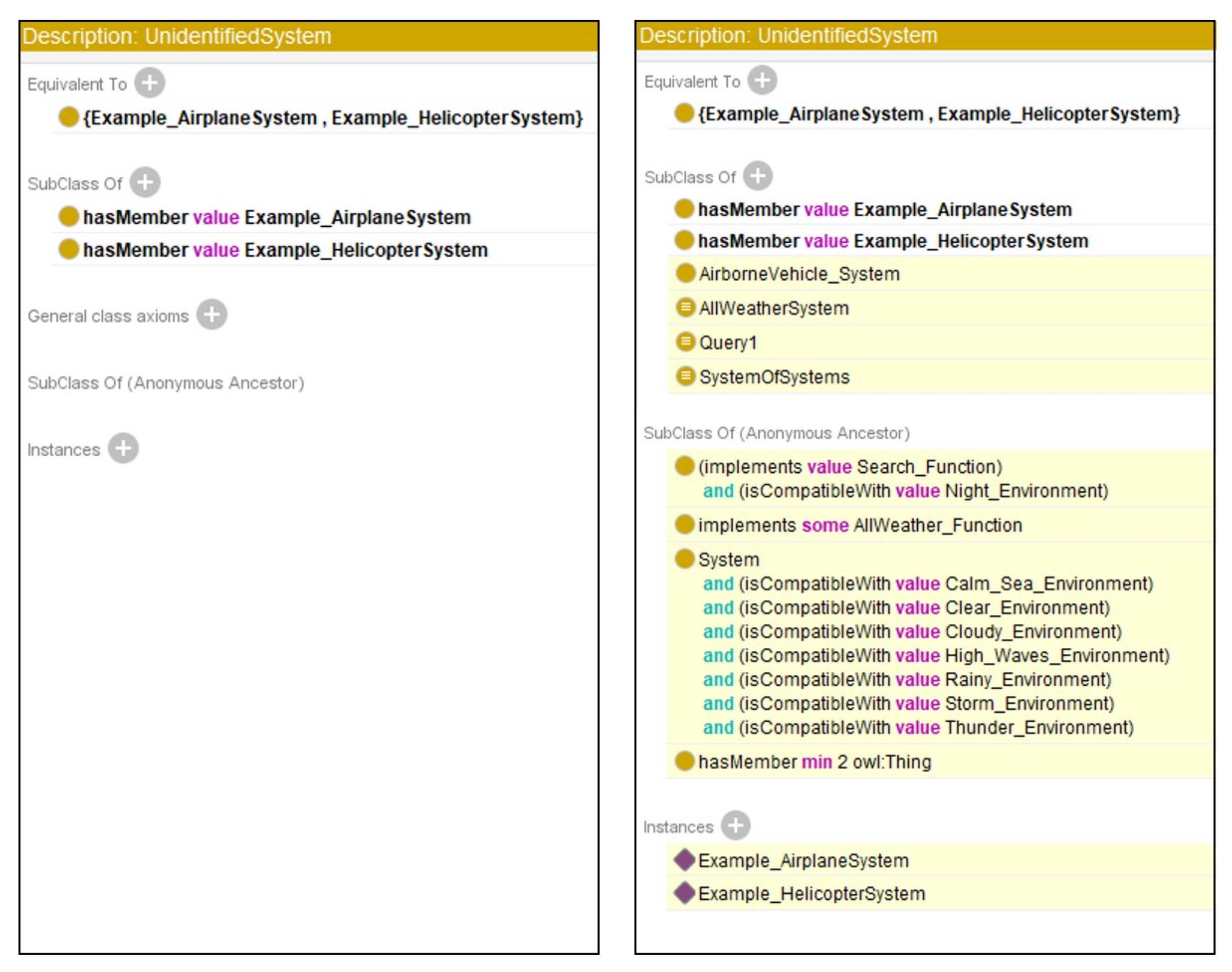
An ontology representation of the information captured in the architecture framework has several advantages. One of these is that a description logic reasoner can process the information, as shown in the previous section. This can indicate both inconsistencies and implicit relationships captured from the architecture framework representation. The additional information added to the ontology could also have been added directly to the UAF representation. However, the ontology model and the reasoning capabilities allow for additional expressiveness. An example of this is the automatic classification of the added SoS class and the UnidentifiedSystem class. Additionally, reasoning provides a way to generate and reduce an available design space based on queries of desired capabilities, performances and more, as seen in the previous section. Another advantage with an ontology is that the scalability is increased. The entities and relationships can be modified or extended as shown, and other existing ontologies can also be included if desired. The open world assumption and the nonunique naming assumption facilitate the interoperability and scalability of information, as mentioned in Section 2. However, more implicit relationships lead to increased computational time for reasoning. The SystemofSystems class contained a simple definition of an SoS to show an example of implicit reasoning. A future implementation of this class could include the five characteristic properties from [4] in the class definition. The reasoner could thereby be used to classify different system concepts as either complex systems or SoS based on fulfilment of the different properties in a more detailed way.
As mentioned before, the Query4 class did not have any inferred individuals or subclasses. Part of the definition for query 4 can, however, be fulfilled by existing alternatives in the ontology. The Example_Helicopter can, for example, fulfil all described conditions except for the no-fly zone environment. Consequently, query 4 could also be fulfilled by an SoS that includes a new system or asset that is capable of getting the rescue subject out of the no-fly zone so that the example helicopter eventually can perform the recover-subject function. An entirely new individual system or asset that fulfils all the conditions must therefore not be developed. However, additional evaluations will of course have to be performed to evaluate the most suitable choice in terms of overall performance, mission cost and success rate, for example.
The SAR example assets that were added to the ontology model were partly based on information from the SMA [42]. Their definitions were kept relatively simple and general for this case study. Similarly, their relationships with the environmental conditions and functions from the UAF should be seen as examples of how they can be assigned to different represented assets. Not all available SAR helicopter and airplane types will necessarily have all-weather capabilities, for example. More SAR assets can be added to the case study in the future to increase the overall design space. A possibility could be to create and include a domain ontology describing all suitable and available SAR aerospace systems. Such an ontology can then act as a statistical database of SAR aircraft types and their corresponding data. This can then be reasoned upon and used to give more suggestions to fulfil user-defined queries for example. However, reasoning does not give suggestions on the number of particular SAR asset and types to be used. Additional investigations must therefore be performed to investigate possible combinations of aircraft and the number of aircraft in different SoSs using, e.g., ABS, as previously mentioned and shown in [38]. Subsystem level analyses are an important part of a holistic SoS design process, as shown in Figure 1. The inclusion of subsystems in the ontology representation is a possible future expansion of the performed case study. Various alternatives of available subsystems can act as additional input for continued design processes using an F/M tree or a matrix of alternatives, for example.
Future work on the presented approach involves additional investigations into both the constituent system and the subsystem levels from Figure 1. Consequently, the incorporation of traditional SE design approaches and processes is an important topic for future work. Transitioning from the ontology description to matrix-based approaches is one possible way of allowing for additional processing and analysing options on the knowledge captured in the ontology. Such a transition also allows for more advanced numerical operations and optimisations. Requirements are an important consideration in any design process and exist on all levels of interest for an SoS. Certain requirements will only be introduced when solutions to required functions are chosen. Consequently, these types of requirements must be included and considered in a continued design process for constituent systems and subsystems. As mentioned previously, ABS can be used to evaluate the overall SoS and check whether performance requirements can be fulfilled throughout different missions.
Another interesting future venture would be to introduce new constituent systems and subsystems to see whether additional functions, capabilities and overarching needs can be fulfilled by the SoS. The approach presented in this paper has mainly been focused on a top-down approach, taking overall needs as its starting point. Another approach, for example, one that starts from a subsystem or CS level, could correspond to a possible design space expansion where the fulfilment of additional needs could be investigated. A new type of SAR helicopter can, for example, be introduced and investigated. If an analysis indicates that additional capabilities can be fulfilled by the new system, it can consequently be a valuable SAR asset to be acquired. An approach with no specific starting point could be enabled by dynamically activating relevant parts of the represented design space. A top-level ontology structure could perhaps facilitate this. However, no top-level ontology was included in the case study, as mentioned previously. It is possible that a metaontology structure could be utilised to dynamically activate relevant domain ontologies and thereby parts of the design space for designing a new aerospace system, for example. A specific ontology for airborne vehicles could be included if the reasoner infers that it is suitable to fulfil a specific query. A new domain ontology describing airborne vehicles could perhaps partly be created by incorporating the aircraft ontology from [17] as a subontology. An airborne vehicle ontology could also possibly include a future implementation of a more specific SAR aircraft ontology describing existing assets, such as helicopters and airplanes, as previously discussed. The aircraft ontology from [17] includes classes for system decomposition and component parameters. It could consequently be used for a continued design process with an F/M tree to allocated solutions to different functions with available aircraft subsystems and components. The outcome could thereafter be used to generate new aircraft concepts to meet the desired functions to be performed for example. In that case, the ontology created for this case study can be used as a middle-level ontology, which describes the relationships between capabilities, activities, functions and the environment in a metaontology structure. This introduces a hierarchical structure of different ontology models but also a consideration of fidelity between the included ontologies.
Additional future work includes investigations of changing overarching needs and surrounding circumstances based on possible future scenarios and forecasts. This can be done to see how the changes influence all levels of the holistic SoS view from Figure 1 and its related design spaces. The alternatives and functions that are least sensitive to such changes can consequently be regarded as the ones that are most resilient and suitable for further development based on forecasts of the near-term future. Even though the presented approach has covered many parts of the holistic SoS design process from Figure 1, there are still many considerations to be included on all levels. These include tactics, strategies and concepts of operations (CONOPS), which are essential elements of an SoS and an SoS design space.

6. Conclusions

This paper has shown how system-of-systems (SoS) needs can be broken down into capabilities and functions using the presented approach with an architecture framework and ontology. A search and rescue (SAR) case study, partly based on the operations of the Swedish Maritime Administration, was performed to test and illustrate this approach. The results from the case study showed that the Unified Architecture Framework (UAF) could be used to perform the initial breakdown of SAR needs into corresponding and required capabilities, activities and functions. An ontology with description logic reasoning capabilities was then used to represent the acquired knowledge from the breakdown with the UAF. The ontology representation was expanded with additional SAR information such as assets and their relationships with the represented environmental conditions. Different defined ontology classes were created to further utilize the reasoning capabilities of the ontology. Finally, reasoning was used to query the ontology representation to give the available design space of alternatives and functions to be performed by, for example, new aerospace system concepts to meet the overarching needs. The performed work thereby contributes an approach with which to meet the complex design challenges of today’s aerospace systems.

Author Contributions

Conceptualisation, L.K.F., I.S., P.K., C.J. and K.A.; methodology, L.K.F.; software, L.K.F.; validation, L.K.F., I.S., P.K., C.J. and K.A.; formal analysis, L.K.F.; investigation, L.K.F.; resources, L.K.F.; data curation, L.K.F.; writing—original draft preparation, L.K.F.; writing—review and editing, L.K.F., I.S., P.K., C.J. and K.A.; visualisation, L.K.F.; supervision, I.S., P.K., C.J. and K.A.; project administration, P.K., C.J.; funding acquisition, P.K., C.J. All authors have read and agreed to the published version of the manuscript.

Funding

This research was funded by the Swedish Innovation Agency (VINNOVA) under grant no. NFFP7/2017-04838.

Institutional Review Board Statement

Not Applicable.

Informed Consent Statement

Not Applicable.

Data Availability Statement

Not Applicable.

Conflicts of Interest

The authors declare no conflict of interest.

Sample Availability

The ontology representation and the diagrams describing the UAF breakdown are available from https://gitlab.liu.se/ludfr93/s2tep-ontologies-and-materials or https://liuonline-my.sharepoint.com/:f:/g/personal/ludfr93_liu_se/EhgWhzF6Z-lEmnYLE8fWU6MBONEnek44IWuxO775OKgtSg?e=GlO7lC (accessed on 19 April 2021).

Abbreviations

The following abbreviations are used in this manuscript:
ABSagent-based simulations
CONOPSconcepts of operations
CSconstituent systems
DoDAFUS Department of Defense Architecture Framework
F/M treefunction-means tree
IAMSARInternational Aeronautical and Maritime Search and Rescue
IRMAInteractive Reconfigurable Matrix of Alternatives
MBSEmodel based systems engineering
MoDAFUK Ministry of Defence Architecture Framework
OBSEontology-based systems engineering
OWLWeb Ontology Language
OWL-DLWeb Ontology Language Description Logics
RDFResource Description Framework
SARsearch and rescue
SEsystems engineering
SMASwedish Maritime Administration
SoSsystem-of-systems
SoSEsystem-of-systems engineering
SysMLSystems Modelling Language
UAFUnified Architecture Framework
UMLUnified Modelling Language

References

  1. Jamshidi, M. System of Systems Engineering Principles and Applications, 1st ed.; CRC Press, Taylor & Francis Group: Boca Raton, FL, USA, 2009. [Google Scholar]
  2. Meadows, D.H. Thinking in Systems: A Primer, 1st ed.; Chelsea Green Publishing: Chelsea, UK, 2008. [Google Scholar]
  3. INCOSE. Systems Engineering HandBook: A Guide for System Life Cycle Processes and Activities, 4th ed.; International Council on Systems Engineering (INCOSE): San Diego, CA, USA, 2015. [Google Scholar]
  4. Maier, M.W. Architecting principles for systems-of-systems. Syst. Eng. J. Int. Counc. Syst. Eng. 1998, 1, 267–284. [Google Scholar] [CrossRef]
  5. Staack, I.; Amadori, K.; Jouannet, C. A holistic engineering approach to aeronautical product development. Aeronaut. J. 2019, 123, 1545–1560. [Google Scholar] [CrossRef] [Green Version]
  6. INCOSE. INCOSE Systems of Systems Primer; INCOSE-TP-2018-003-01.0; INCOSE: San Diego, CA, USA, 2018. [Google Scholar]
  7. Lane, J.A. What Is a System of Systems and Why Should I Care? USC-CSSE-2013-001; University of Southern California: Los Angeles, CA, USA, 2013; ISBN 978-3-642-11828-9. [Google Scholar]
  8. CAE. Capability Engineering. 2019. Available online: https://www.cae.com/media/documents/Defence_Security/Services_-_Documents/datasheet.capability.engineering.pdf (accessed on 14 March 2021).
  9. Kossiakoff, A.; Sweet, W.N.; Seymour, S.J.; Biemer, S.M. Systems Engineering Principles and Practice, 2nd ed.; John Wiley & Sons: Hoboken, NY, USA, 2011. [Google Scholar]
  10. Dahmann, J.; Lane, J.A.; Rebovich, G.; Lowry, R. Systems of systems test and evaluation challenges. In Proceedings of the 2010 5th International Conference on System of Systems Engineering, Loughborough, UK, 22–24 June 2010; pp. 1–6. [Google Scholar] [CrossRef]
  11. Boardman, J.; Sauser, B. System of Systems—The meaning of of. In Proceedings of the 2006 IEEE/SMC International Conference on System of Systems Engineering, Los Angeles, CA, USA, 24–26 April 2006; IEEE: Los Angeles, CA, USA, 2006; Volume 1, pp. 118–123. [Google Scholar]
  12. Object Management Group (OMG). Unified Architecture Framework. Available online: https://www.omg.org/uaf/index.htm (accessed on 14 March 2021).
  13. Van Ruijven, L.C. Ontology for systems engineering. Conference on Systems Engineering Research, CSER’13. Procedia Comput. Sci. 2012, 16, 383–392. [Google Scholar] [CrossRef] [Green Version]
  14. Hennig, C.; Viehl, A.; Kämpgen, B.; Eisenmann, H. Ontology-Based Design of Space Systems. In Proceedings of the International Semantic Web Conference, Kobe, Japan, 17–21 October 2016; pp. 308–324. [Google Scholar]
  15. Langford, G.; Langford, T. The making of a system of systems: Ontology reveals the true nature of emergence. In Proceedings of the 12th System of Systems Engineering Conference (SoSE), Waikoloa, HI, USA, 18–21 June 2017; pp. 1–5. [Google Scholar]
  16. Dogan, H.; Henshaw, M.J.; Johnson, J. An incremental hybridisation of heterogeneous case studies to develop an ontology for capability engineering. In Proceedings of the INCOSE International Symposium, Rome, Italy, 9–12 July 2012; INCOSE: Rome, Italy, 2012; Volume 22, pp. 956–971. [Google Scholar]
  17. Ast, M.; Glas, M.; Roehm, T. Creating an ontology for aircraft design, an experience report about development process and the resulting ontology. In Proceedings of the Deutscher Luft-und Raumfahrtkongress, Stuttgart, Germany, 10–12 September 2013. [Google Scholar]
  18. Yang, L.; Cormican, K.; Yu, M. Ontology-based systems engineering: A state-of-the-art review. Comput. Ind. 2019, 111, 148–171. [Google Scholar] [CrossRef]
  19. Noy, N.F.; McGuinnes, D.L. Ontology Development 101: A Guide to Creating Your First Ontology; Stanford University: Stanford, CA, USA, 2000. [Google Scholar]
  20. Allemang, D.; Hendler, J. Semantic Web for the Working Ontologist—Effective Modeling in RDFS and OWL, 2nd ed.; Elsevier: Waltham, MA, USA, 2011. [Google Scholar]
  21. Horridge, M.; Knublauch, H.; Rector, A.; Stevens, R.; Wroe, C.; Jupp, S.; Moulton, G.; Drummond, N.; Brandt, S. A Practical Guide To Building OWL Ontologies Using Protégè 4 and CO-ODE Tools Edition 1.3; Technical Report; The University of Manchester: Manchester, UK, 2011. [Google Scholar]
  22. Mittal, S.; Diallo, S.; Tolk, A. Emergent Behavior in Complex Systems Engineering—A Modeling and Simulation Approach, 1st ed.; John Wiley & Sons: New York, NY, USA, 2018. [Google Scholar]
  23. Wagner, D.A.; Bennett, M.B.; Karban, R.; Rouquette, N.; Jenkins, S.; Ingham, M. An Ontology for State Analysis: Formalizing the Mapping to SysML. In Proceedings of the 2012 IEEE Aerospace Conference, Big Sky, MT, USA, 3–10 March 2012; pp. 1–16. [Google Scholar]
  24. Jenkins, S. Introduction to System Modeling and Ontologies. Available online: https://trs.jpl.nasa.gov/bitstream/handle/2014/42081/11-1269.pdf?sequence=1 (accessed on 19 April 2021).
  25. Wardhana, H.; Ashari, A.; Sari, A.K. Transformation of SysML Requirement Diagram into OWL Ontologies. Int. J. Adv. Comput. Sci. Appl. IJACSA 2020, 11, 106–114. [Google Scholar] [CrossRef]
  26. Arp, R.; Smith, B.; Spear, A.D. Building Ontologies with Basic Formal Ontology; The MIT Press: Cambridge, MA, USA, 2015. [Google Scholar]
  27. Smith, B. Basic Formal Ontology 2.0 Specification and User’s Guide; National Center for Ontological Research: Buffalo, NY, USA, 2015. [Google Scholar]
  28. Mascardi, V.; Cordì, V.; Rosso, P. A Comparison of Upper Ontologies. In Proceedings of the 8th AI*IA/TABOO Joint Workshop “From Objects to Agents”: Agents and Industry: Technological Applications of Software Agents, Genova, Italy, 24–25 September 2007; pp. 55–64. [Google Scholar]
  29. Dickerson, C.E.; Mavris, D.N. Architecture and Principles of Systems Engineering, 1st ed.; CRC Press: Boca Raton, FL, USA, 2010. [Google Scholar]
  30. Robotham, A.J. The Use of Function/Means Trees for Modelling Technical, Semantic and Business Functions. J. Eng. Des. 2002, 243–251. [Google Scholar] [CrossRef]
  31. Lynch, K.; Ramsey, R.; Ball, G.; Schmit, M.; Collins, K. Conceptual design acceleration for cyber-physical systems. In Proceedings of the Annual IEEE International Systems Conference (SysCon), Montreal, QC, Canada, 24–27 April 2017; pp. 1–6. [Google Scholar]
  32. Schmit, M.; Briceno, S.; Collins, K.; Mavris, D.; Lynch, K.; Ball, G. Semantic design space refinement for model-based systems engineering. In Proceedings of the 10th Annual International Systems Conference, SysCon 2016, Orlando, FL, USA, 18–21 April 2016. [Google Scholar] [CrossRef]
  33. Rainey, L.B.; Tolk, A. Modeling and Simulation Support for System of Systems Engineering Applications, 1st ed.; Wiley: Hoboken, NJ, USA, 2015. [Google Scholar]
  34. Papageorgiou, A. Design Optimization of Unmanned Aerial Vehicles—A System of Systems Approach. Ph.D. Thesis, Linköping University, Linköping, Sweden, 2019. [Google Scholar]
  35. Papageorgiou, A.; Ölvander, J.; Amadori, K.; Jouannet, C. Multidisciplinary and Multifidelity Framework for Evaluating System-of-Systems Capabilities of Unmanned Aircraft. J. Aircr. 2020, 57, 317–332. [Google Scholar] [CrossRef]
  36. Jändel, M.; Bivall, P.; Hammar, P.; Johansson, R.; Kamrani, F.; Quas, M.J. Visual Analytics—Perspectives on the Field of Interactive Visualization; Swedish Defence Research Agency (FOI): Stockholm, Sweden, 2016. [Google Scholar]
  37. Knöös Franzén, L.; Staack, I.; Jouannet, C.; Krus, P. An Ontological Approach to System of Systems Engineering in Product Development. In Proceedings of the 10th Aerospace Technology Congress, Stockholm, Sweden, 8–9 October 2019; Swedish Society of Aeronautics and Astronautics: Stockholm, Sweden, 2019; pp. 35–44. [Google Scholar]
  38. Knöös Franzén, L.; Schön, S.; Papageorgiou, A.; Staack, I.; Ölvander, J.; Krus, P.; Jouannet, C.; Amadori, K. A System of Systems Approach for Search and Rescue Missions. In Proceedings of the AIAA Scitech 2020 Forum, Orlando, FL, USA, 6–10 January 2020; American Institute of Aeronautics and Astronautics: Orlando, FL, USA, 2020; pp. 1–16. [Google Scholar]
  39. Object Management Group (OMG). Unified Architecture Framework (UAF) Domain Metamodel, Version 1.1; Object Management Group (OMG): Needham, MA, USA, 2020. [Google Scholar]
  40. No Magic, Inc. UAF Plugin 19.0 LTR Documentation. Available online: https://docs.nomagic.com/display/UAFP190/UAF+elements (accessed on 14 March 2021).
  41. Halléhn, M. Svenskt Program för Sjö- och Flygräddning. In Sjöfartsverket Document Nr: RADDALIV-6-182; Sjöfartsverket: Norrköping, Sweden, 2019. (In Swedish) [Google Scholar]
  42. Sjöfartsverket. Sjö-och Flygräddning. Available online: https://www.sjofartsverket.se/Sjofart/Sjo--och-flygraddning/ (accessed on 14 March 2021).
  43. ICAO; IMO. IAMSAR Manual—International Aeronautical and Maritime Search and Rescue Manual—Volume 1 Organization and Management, 10th ed.; International Civil Aviation Organization and International Maritime Organization: Montréal, QC, Canada, 2016. [Google Scholar]
  44. ICAO; IMO. IAMSAR Manual—-International Aeronautical and Maritime Search and Rescue Manual—-Volume 2 Mission Co-ordination, 7th ed.; International Civil Aviation Organization and International Maritime Organization: Montréal, QC, Canada, 2016. [Google Scholar]
  45. ICAO; IMO. IAMSAR Manual—International Aeronautical and Maritime Search and Rescue Manual—Volume 3 Mobile Facilities, 10th ed.; International Civil Aviation Organization and International Maritime Organization: Montréal, QC, Canada, 2016. [Google Scholar]
  46. Object Management Group (OMG). Unified Architecture Framework (UAF) Sample Problem (Informative); Technical Report; OMG Unified Architecture Framework: Object Management Group (OMG): Needham, MA, USA, 2018. [Google Scholar]
  47. Musen, M.A. The Protégé project. A look back and a look forward. AI Matters Assoc. Comput. Mach. Specif. Interest Group Artif. Intell. 2015, 1. [Google Scholar] [CrossRef]
  48. Knöös Franzén, L. S2TEP Ontologies. Available online: https://gitlab.liu.se/ludfr93/s2tep-ontologies-and-materials; https://liuonline-my.sharepoint.com/:f:/g/personal/ludfr93_liu_se/EhgWhzF6Z-lEmnYLE8fWU6MBONEnek44IWuxO775OKgtSg?e=GlO7lC (accessed on 19 April 2021).
Figure 1. The holistic design process for a system of systems (SoS). Adapted from [5].
Aerospace 08 00118 g001
Figure 2. The overall approach and purpose of this paper.
Aerospace 08 00118 g002
Figure 3. The presented work positioned relative to related areas and disciplines.
Aerospace 08 00118 g003
Figure 4. An illustration of the approach to breaking down SoS needs with an architecture framework and ontology to generate an SoS design space.
Aerospace 08 00118 g004
Figure 5. A Unified Modelling Language (UML) diagram of the breakdown approach, with the relationships between needs, capabilities, activities, functions, means and the environment.
Aerospace 08 00118 g005
Figure 6. The ontology development process described in [37], with its eight consecutive steps.
Aerospace 08 00118 g006
Figure 7. An example of a Strategic Structure (St-Sr) view of the Unified Architecture Framework (UAF) that describes the capability connectivity of the overall search and rescue (SAR) system.
Aerospace 08 00118 g007
Figure 8. An example of an Operational Traceability (Op-Tr) view of the UAF that describes the connection between capabilities and operational activities.
Aerospace 08 00118 g008
Figure 9. The Operational Processes (Op-Pr) view of the UAF, which describes the hierarchy of operational activities.
Aerospace 08 00118 g009
Figure 10. An example of a Resource Traceability (Rs-Tr) view of the UAF that describes the connection between operational activities and functions that implement them.
Aerospace 08 00118 g010
Figure 11. The Resource Processes (Rs-Pr) view of the UAF, showing a hierarchy of SAR functions.
Aerospace 08 00118 g011
Figure 12. The Parameters Environment (Pm-En) view of the UAF, illustrating possible locations, conditions and environments that the SAR system can operate in.
Aerospace 08 00118 g012
Figure 13. The ontology class hierarchy where the general classes from the UAF breakdown are represented (left). The definition of the Function class is shown to the right with its corresponding individuals (right).
Aerospace 08 00118 g013
Figure 14. The definition of the individual describing a Search Function.
Aerospace 08 00118 g014
Figure 15. The expanded ontology class hierarchy (left) and the definition of the Example Airplane System individual (right).
Aerospace 08 00118 g015
Figure 16. The definitions of the AllWeather class (left) and the SystemOfSystems class (right).
Aerospace 08 00118 g016
Figure 17. The definitions for the four different user-defined queries.
Aerospace 08 00118 g017
Figure 18. The UnidentifiedSystem class definition before (left) and after reasoning (right). Inferences made by the reasoner are shown with a yellow background.
Aerospace 08 00118 g018
Figure 19. The Query1 and Query2 class definitions with the inferences made by the reasoner.
Aerospace 08 00118 g019
Figure 20. The inferred class hierarchy of the expanded ontology.
Aerospace 08 00118 g020
Publisher’s Note: MDPI stays neutral with regard to jurisdictional claims in published maps and institutional affiliations.

