1. Introduction
Disturbance in the power system is a significant concern for many electric utilities due to its impact on the operation and reliability of the overall system. Besides, it may cause damage to vital equipment in the power system such as a generator, transmission line, and transformer in case the operator does not address the fault with speed and accuracy, which results in large scale electric outage, economic losses, and the possibility of loss of life. Thus, the protection system with the ability to accurately identify, locate, and classify faults in the power system needs to be implemented into the system to ensure the quick and correct response to fault clearing.
The algorithm to detect and classify faults in power transmission lines has been widely developed based on different types of methodologies. The wavelet transform is one of the popular methods for fault detection and discrimination due to its ability to analyze high-frequency components [
1,
2,
3,
4,
5,
6]. The discrete wavelet transform (DWT)-based methodology has been used for the detection of transmission line faults [
1]. Three-phase voltage signals are decomposed by the Daubechies wavelet (db4). By considering the results, the coefficient details at level 4 clearly distinguish the different types of faults in the power system. The new differential relaying scheme based on the transient energy extracted using the DWT in the current signals of each line distinguishes between external and internal faults under all operating conditions [
2]. This paper proposed an adaptive technique to detect low-impedance faults (LIFs) and high-impedance faults (HIFs) and classified LIFs in transmission systems depending on the DWT. The current of each phase is analyzed by using the DWT (db1), and faults are classified through comparison with the current approximation coefficient (Sg) and current detail coefficients (Da, Db, and Dc) [
3]. This reveals that the wavelet transform is significant in the detection and classification of faults in power systems. However, the algorithm can be improved by using artificial intelligence (AI).
AI has been combined with wavelets to improve the accuracy of fault classification algorithms in electrical systems [
7,
8,
9,
10,
11,
12]. AI enhances accuracy and reduces the time to classify faults. Wavelets with neural networks (NNs) have been used to detect and identify fault types in transmission line systems [
7,
8,
9,
10,
11]. The algorithm makes use of wavelet transform-based approximate coefficients of three-phase voltage and current signals obtained over a quarter cycle to detect and classify faults. Fault detection and classification and fault location estimation are carried out using an artificial neural network (ANN), and the alienation coefficients of current signals are used as ANN input [
7]. This paper presents an application of NNs and wavelet transforms for fault classification in transmission lines in comparison with particle swarm optimization–artificial neural network (PSO–ANN)-, back-propagation neural networks (BPNN)-, and support-vector machines (SVM)-based classification schemes. The PSO–ANN technique has a very high accuracy (99.912%) in the classification of power system faults [
11]. This paper presents a survey and review of the research and developments in the field of fault detection, classification, and location in transmission networks [
12].
In addition, wavelets are used to detect faults or abnormalities in transformers [
13,
14,
15,
16,
17,
18,
19,
20,
21,
22]. They are used to detect vibrations or electrical signals. Transformer vibration signals are decomposed into several empirical wavelet functions. The signals are calculated to construct the eigenvectors of the transformer vibration signals for classifying three different working conditions (normal conditions, winding axial deformation, and winding radial deformation) [
13]. Most papers use wavelets to classify inrush and internal and external faults. The differential current is used as input for the wavelet transform to analyze faults [
14,
15,
16,
17,
18,
19,
20,
21]. The boundary wavelet transform is implemented in the differential protection of power transformers to distinguish internal faults from other disturbances. The method is designed for real-time applications and implemented in a digital signal processor for real-time analysis [
14]. The algorithm distinguishes between internal faults and inrush currents in power transformers. Fault currents are analyzed by using the DWT to evaluate their remarkable characteristic values, and the highest values produced by the total wavelet correlation matrix are used to identify inrush and internal fault currents in power transformers. The results are validated with an experimental test setup [
18]. Moreover, the algorithm can identify fault occurrence with the continuous wavelet transform (CWT) and improve conventional current differential protection methods in the presence of current transformer (CT) saturation [
20]. A spectrum of wavelets has been used for the prediction of winding insulation defects in transformers [
21].
From the literature review, it can be seen that the wavelet transform methodology has been widely used in power system fault analysis. However, many studies only focus on transmission lines or transformers, and few have combined the two components when analyzing systems. Most of the references use wavelets to detect and identify fault types in electrical systems, but they do not analyze the mother wavelet [
1,
2,
3,
4,
5,
6,
7,
8,
9,
10,
11,
12,
13,
14,
15,
16,
17,
20,
21]. Additionally, there are research articles that compare mother wavelets [
18,
19,
22,
23]. They study the comparative use of 16 different wavelets for fault classification in overhead transmission line systems. However, it is revealed that the Db4 wavelet completely satisfies the fault classification algorithm [
23].
Another point is that the result from a simulation that has been widely used may not correctly represent the actual system in the real world due to some parameter and factor that has been simplified, which might affect the result. In terms of wavelet transform application, the research using wavelets to detect and discriminate fault types on power systems might not take effects from different mother wavelets into consideration when evaluating the performance of the algorithm. Thus, this paper presents the effect of mother wavelets on the performance of fault classification algorithms in the power system. The result in terms of accuracy between different mother wavelets was evaluated by using an experimental setup modeled after the actual system with a transmission line connected to the power transformer.
The paper is divided into six sections as follows. The second section provides the fundamentals and theory of the DWT. The experimental setup and system characteristics are presented in
Section 3. The details of the fault classification algorithm used in this study are contained in
Section 4. The results and conclusions of the study are summarized in
Section 5 and
Section 6, respectively.
2. Fundamentals and Theory
The wavelet transform is a method based on signal processing that was developed from Fourier and short-Fourier transforms for suitable specific applications. The time width and frequency can be adjusted for optimal analysis.
The wavelet theory based on mathematics integrates small signals into one signal. The small signal is the wavelet, which has a specific character because the wavelet is a wave-like oscillation with an amplitude that begins at zero, increases, and then decreases back to zero. Therefore, any signals in the wavelet theory are a combination of wavelet groups that are structured from the same function. This function is the origin wavelet called the mother wavelet. The signals are caused by the mother wavelet stretching (scaling: a) or shrinking (shifting: k) the wavelet itself, which occurs as a position change along the time axis.
DWT signal analysis can select many scales (m) and many positions (k) for integrated wavelets and can form a signal at the interest scale. When integrating the signal at all resolutions, the actual input signal is received. In multilevel analysis, the scale of analysis is reduced by two times. Hence, this is a DWT-type dyadic wavelet transform, as described in Equation (1) [
24].
where
Signals are decomposed by the wavelet. The mother wavelet is a filter signal that separates the following two channels:
The high-frequency component will be used to analyze signal during transient state.
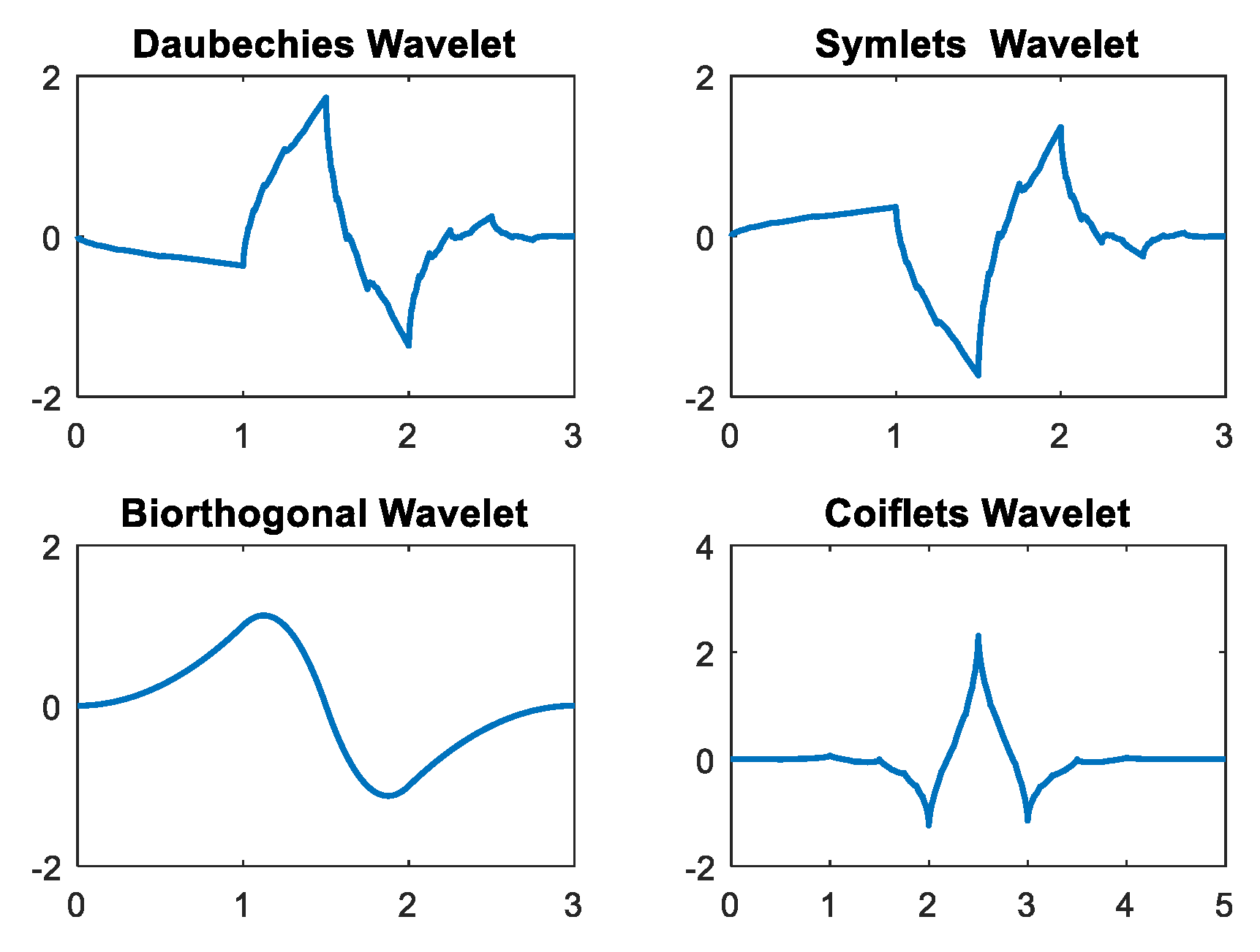
The mother wavelets used in the DWT are db, sym, coif, and bior [
24]. Each mother wavelet provides a differential coefficient because of its differential characteristic signal, as shown in
Figure 1.
The Daubechies (db) mother wavelet has asymmetric basic functions, while the symlets (Sym) mother wavelet has the least asymmetric basic functions. The biorthogonal (Bior) mother wavelet has symmetric basic functions, and the coif1 mother wavelet has nearly asymmetric basic functions. It is necessary to choose a suitable mother wavelet for increased efficiency.
3. Experimental
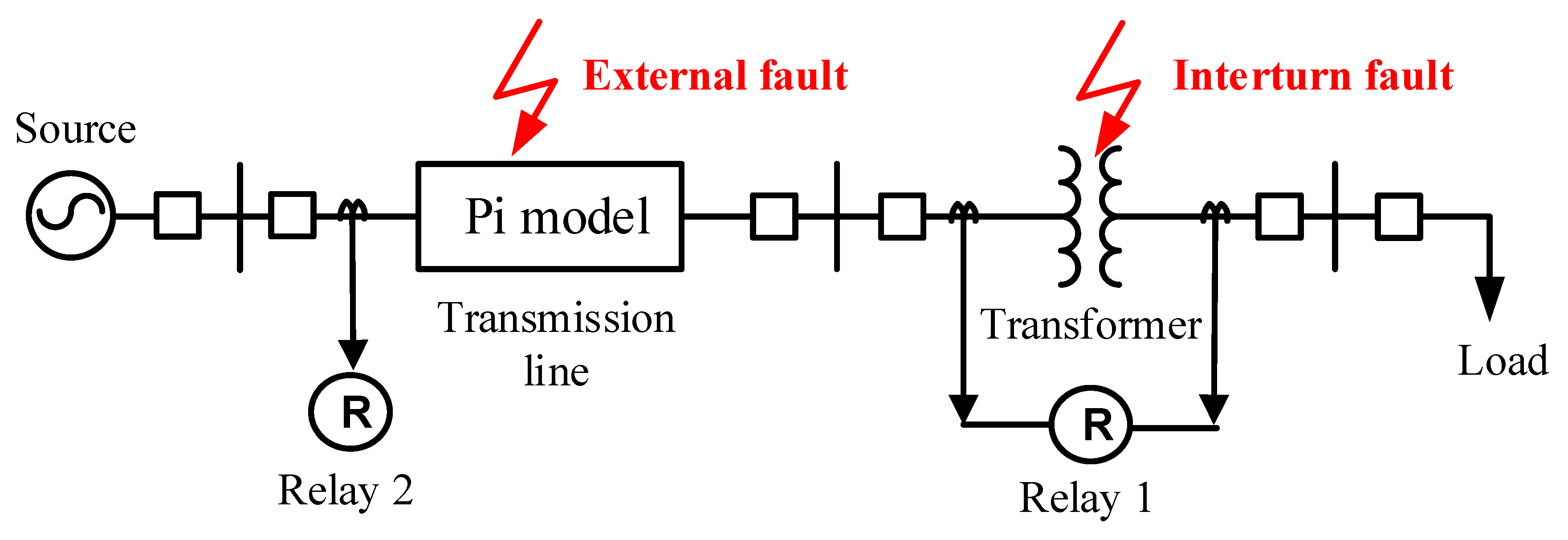
In this section, the faults that occur in transmission lines and transformers are tested by using the experimental setup. The difference current signals and transients generated from the experimental setup are detected and recorded for analysis with a wavelet. The experimental model is shown in
Figure 2.
Figure 2 shows the fault simulation circuit in the case of transmission lines connected to a transformer. The 40 km 115 kV transmission lines are calculated to be resistor, inductor and capacitor (RLC) parameters that are connected to a nominal pi model and a 15 kVA, 440/220 V transformer. The transformer is designed to accept internal short-circuiting. The design of the transformer permits a tap change every 10% of both the primary and secondary sides to test internal faults in the transformer. Moreover, the faults occurring in the transmission lines are tested by following these conditions:
The fault types include a single line to the ground fault, a double line to the ground fault, a line to line fault, and a three-phase fault.
The fault positions are designated to any phases of the transmission lines at lengths of 30%, 50%, and 70% of the length of the transmission line.
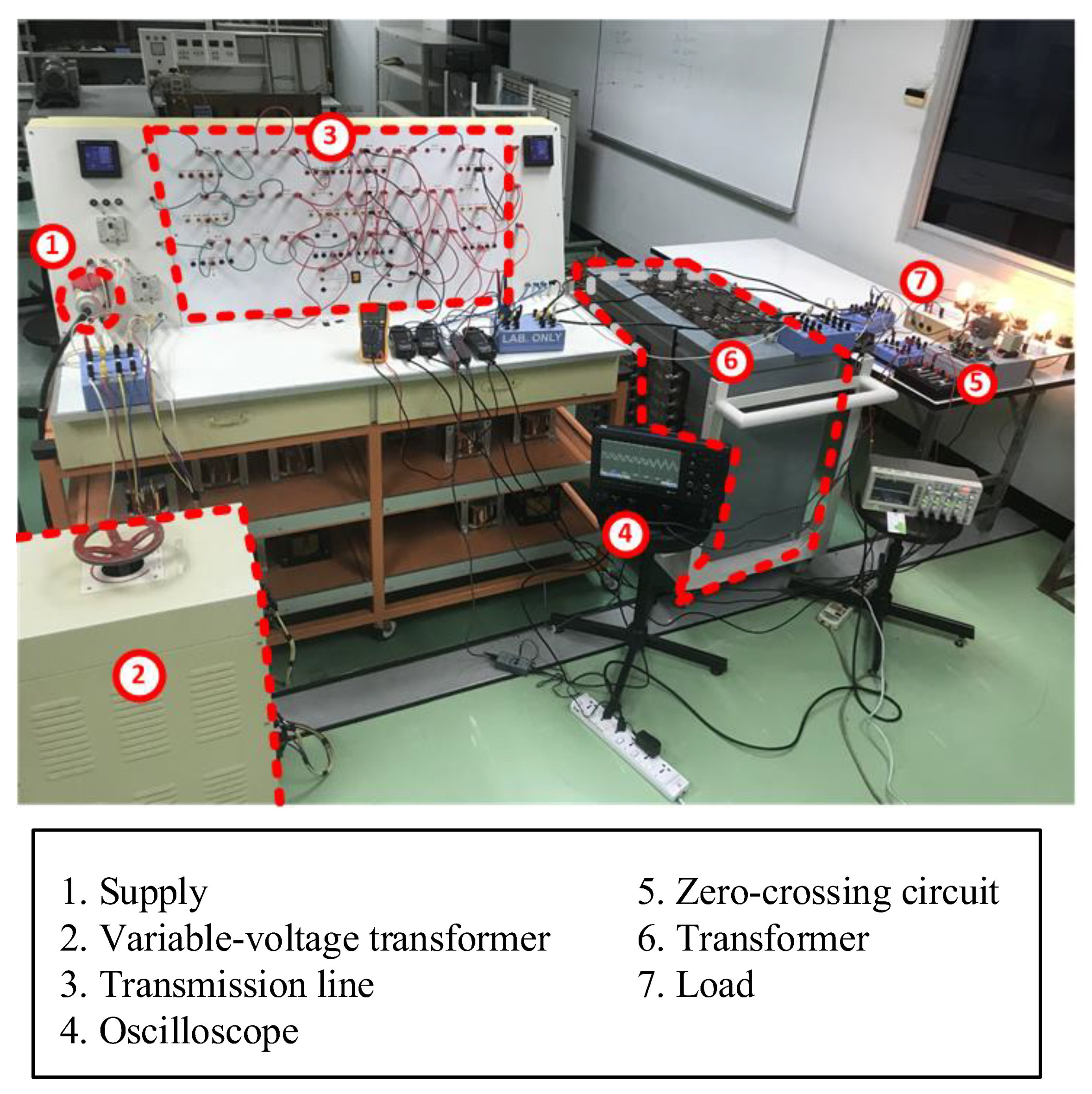
The experimental setup is shown in
Figure 3.
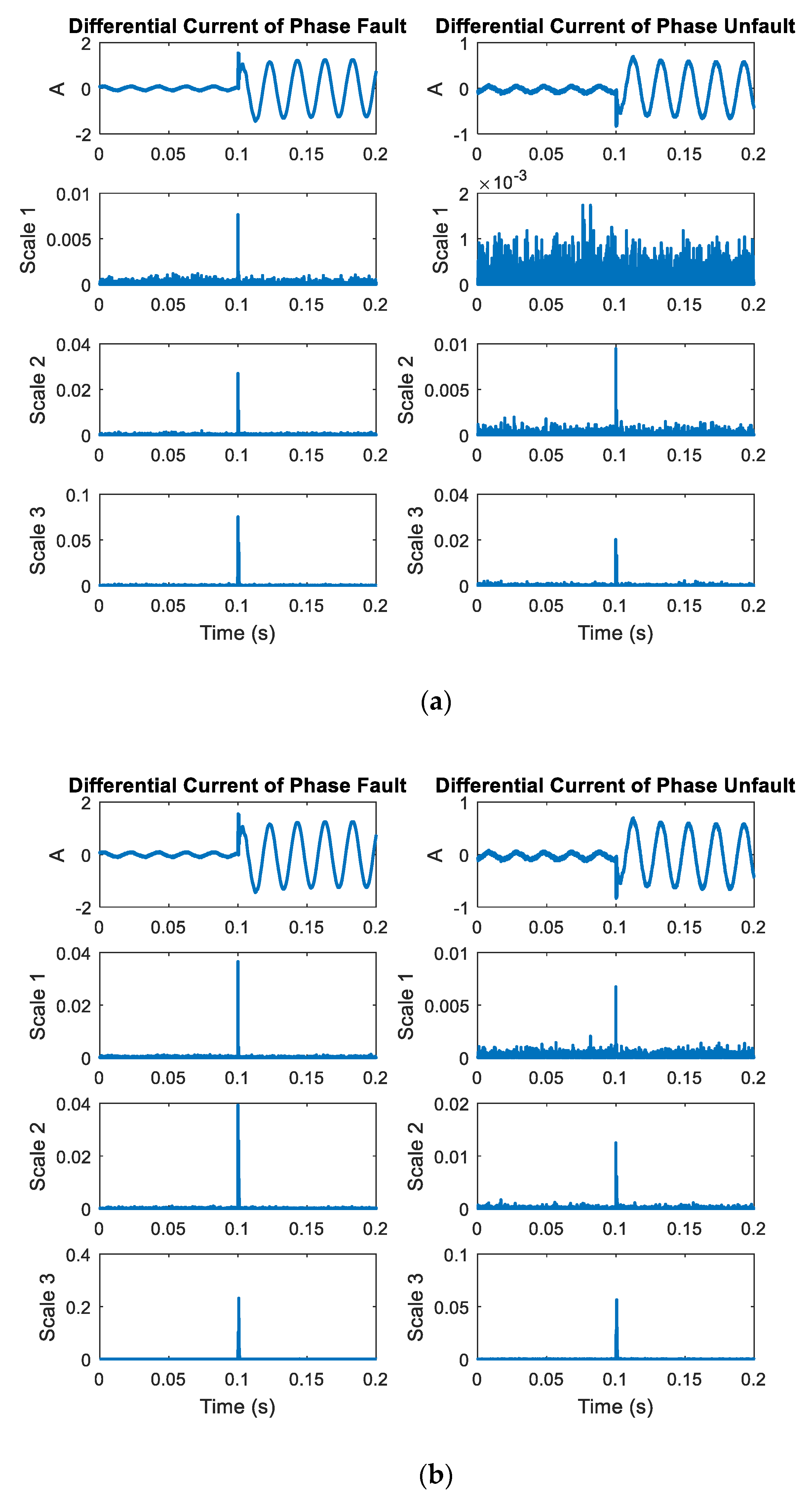
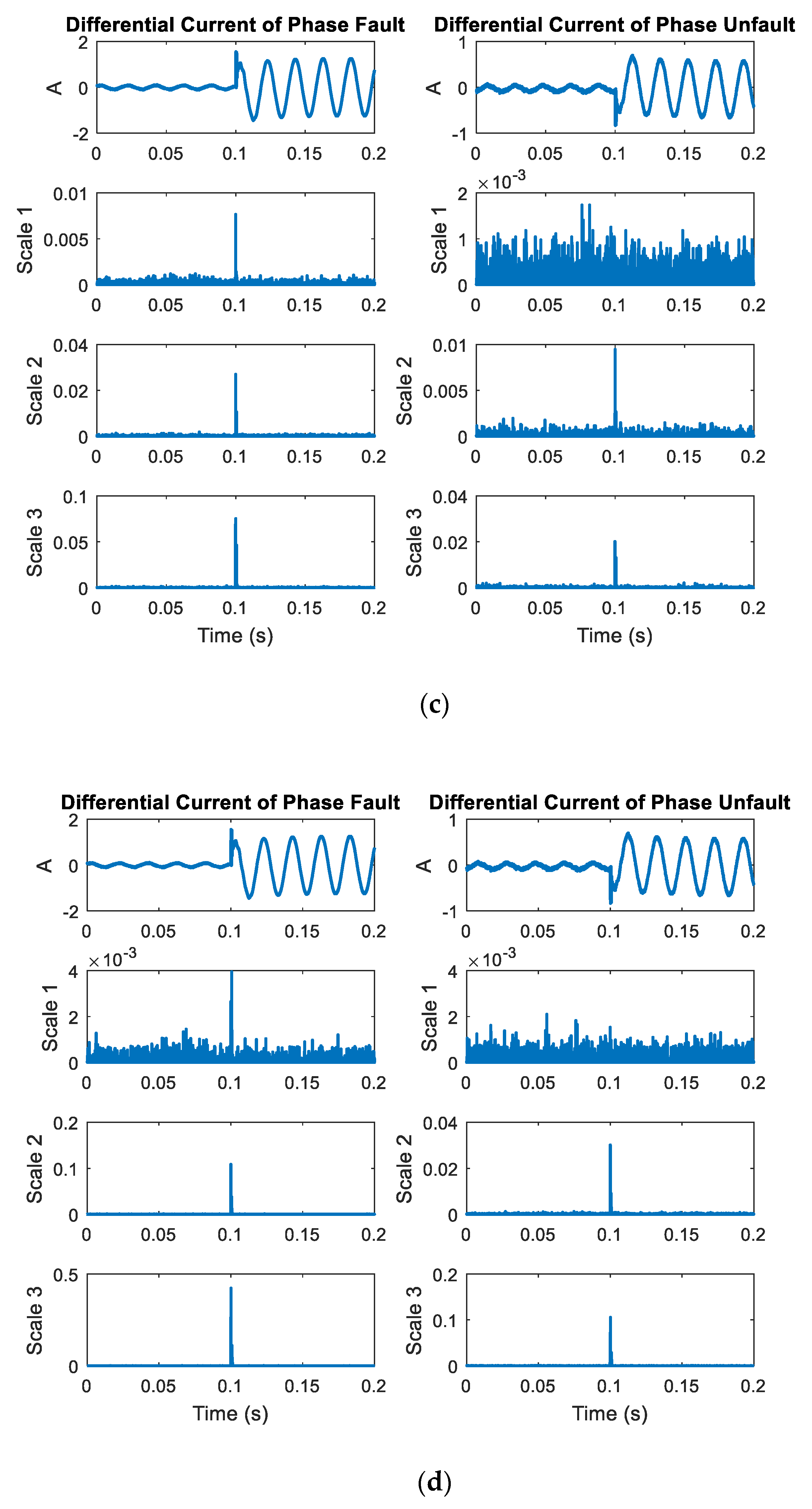
After recording the differential current from the transformer, the differential current is obtained through the wavelet transform method. The current signal is transformed using the DWT to extract high-frequency components at scales 1–3 with different mother wavelets, such as the Daubechies (db), symlets (sym), biorthogonal (bior), and Coiflets (coif) wavelets. The coefficient from the DWT is varied depending on various factors, and this coefficient is squared to emphasize the change in coefficient. The four mother wavelets are utilized to decompose the differential current signals. The DWT coefficients of the phase faults are larger than those of the phase unfaults.
The example of differential current obtained from the transformer (relay 1) in case of internal fault and the coefficient after using different mother wavelets is shown in
Figure 4. From the figure, it can be seen that the DWT signals at scale 1 generate much noise compared with those at scales 2–3. The coefficients at scales 2–3 are notable when faults occur, and at scale 3, a lower frequency can be detected compared to that at scale 2. Thus, this research chose the coefficients at scale 2 for analysis of the fault types.
4. Fault Classification
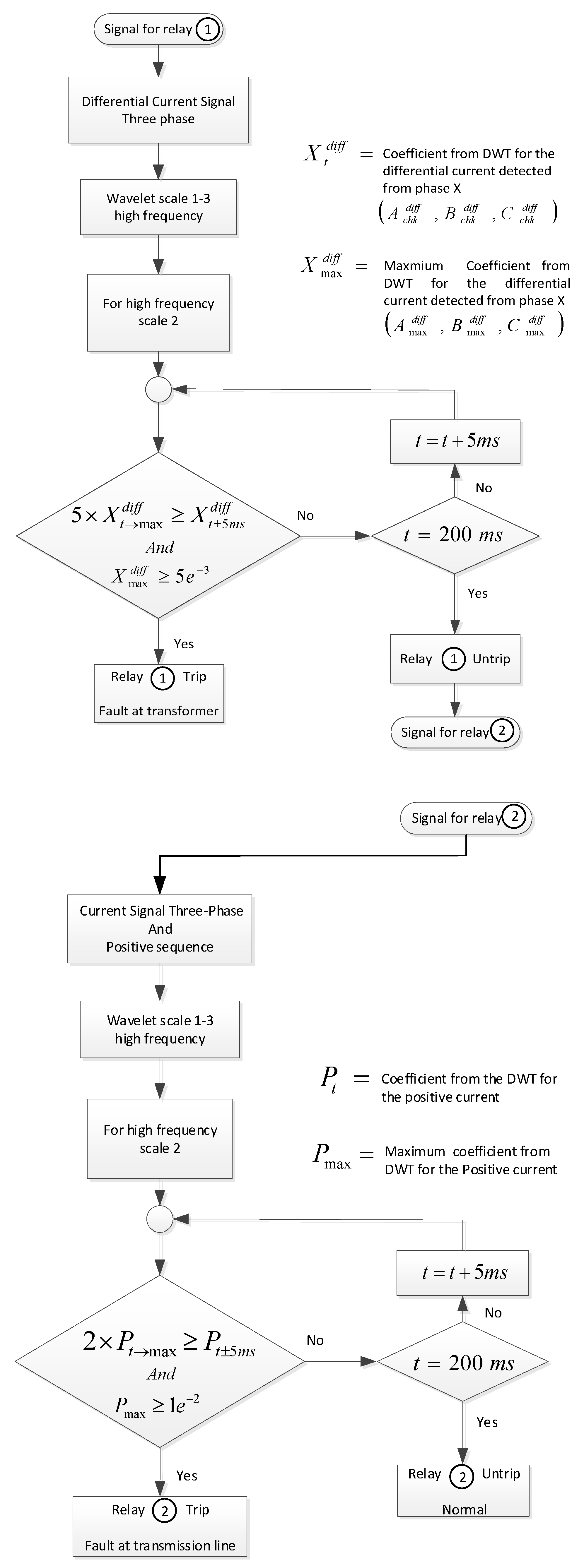
The fault classification algorithm using in this research was designed based on the DWT methodology as described in the flowchart in
Figure 5. The operation of the algorithm detecting the fault on the power system consists of a transmission line and a transformer by first checking the status of relay 1 (at the transformer). Relay 1 obtains the differential current signals from the transformer and extracts the coefficient value using DWT. This algorithm considers the maximum coefficients at scale 2 every 5 ms (1/4 cycle). When the coefficients changes more than five times and attains values larger than 5 × 10
−3, an internal fault occurs. This status will signal the relay 1 to trip. Otherwise, it is an external fault and will send a signal for relay 2 (at the transmission line).
For the relay 2, the required signals from the transmission line are the positive sequence of the three-phase current signal. These signals will input through DWT to extract the coefficient value. The fault classification conditions in relay 2 are the maximum coefficients at scale 2 of the positive sequence every 5 ms (1/4 cycle). When the coefficients change more than 2 times and attain values larger than 1 × 10⁻², a fault occurs. This status will signal the relay 2 to trip.
The designed fault classification algorithm and testing of the proposed algorithm consists of testing of the experimental setup to obtain the signal from both relays 1 and 2. The number of case studies was varied with the different conditions to obtain a number of data points, as shown in
Table 1. The data were divided into three sets with a total number of data points of 1776; the first set of data was used for algorithm design—50% (888 data points), the second set of data was used for algorithm testing—25% (444 data points), and the last set of data was used for a case study—25% (444 data points). The first set was used to design the condition within the algorithm with an accuracy of more than 95%. The second set of data, different from the first set, was used to test the accuracy of the algorithm. The third set of the data, the newer data differentiated from the first two sets, was used as the case study to evaluate the performance of the proposed algorithm.
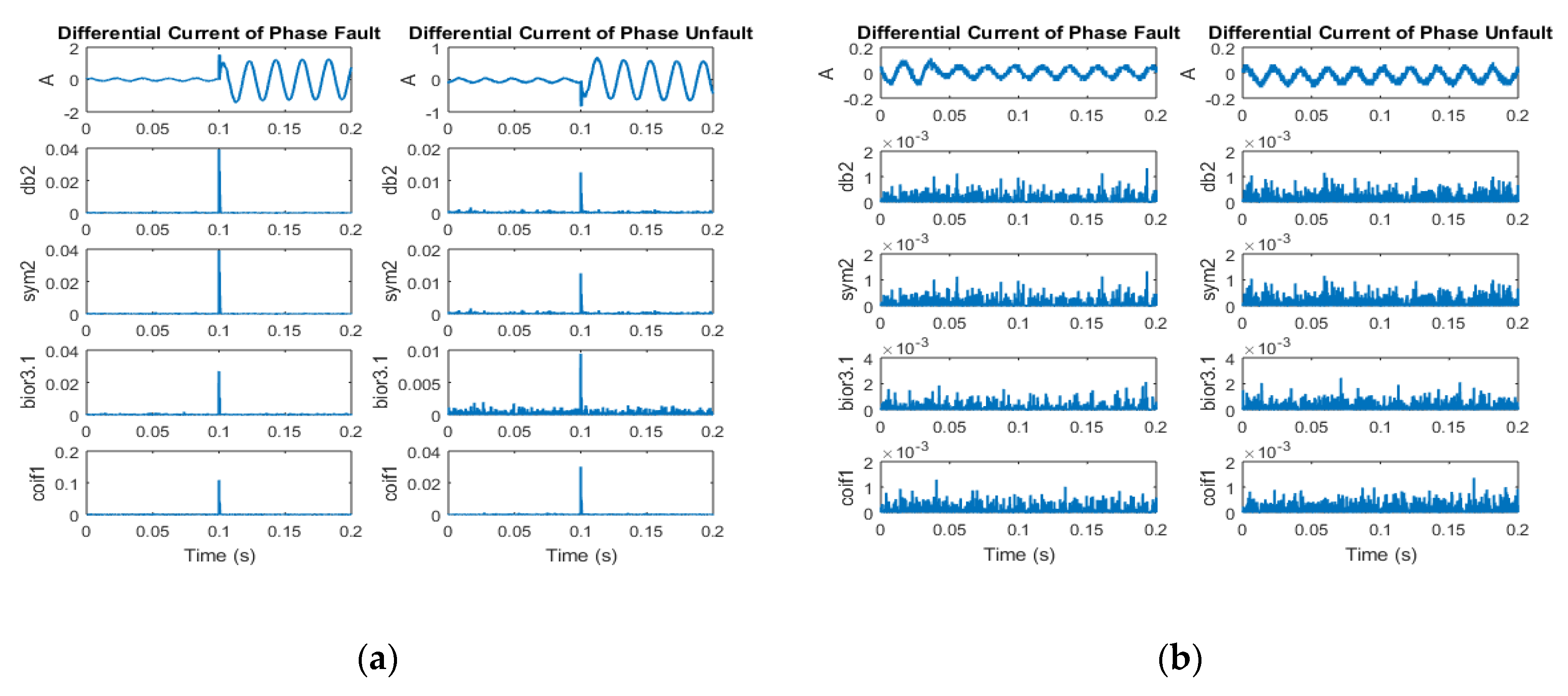
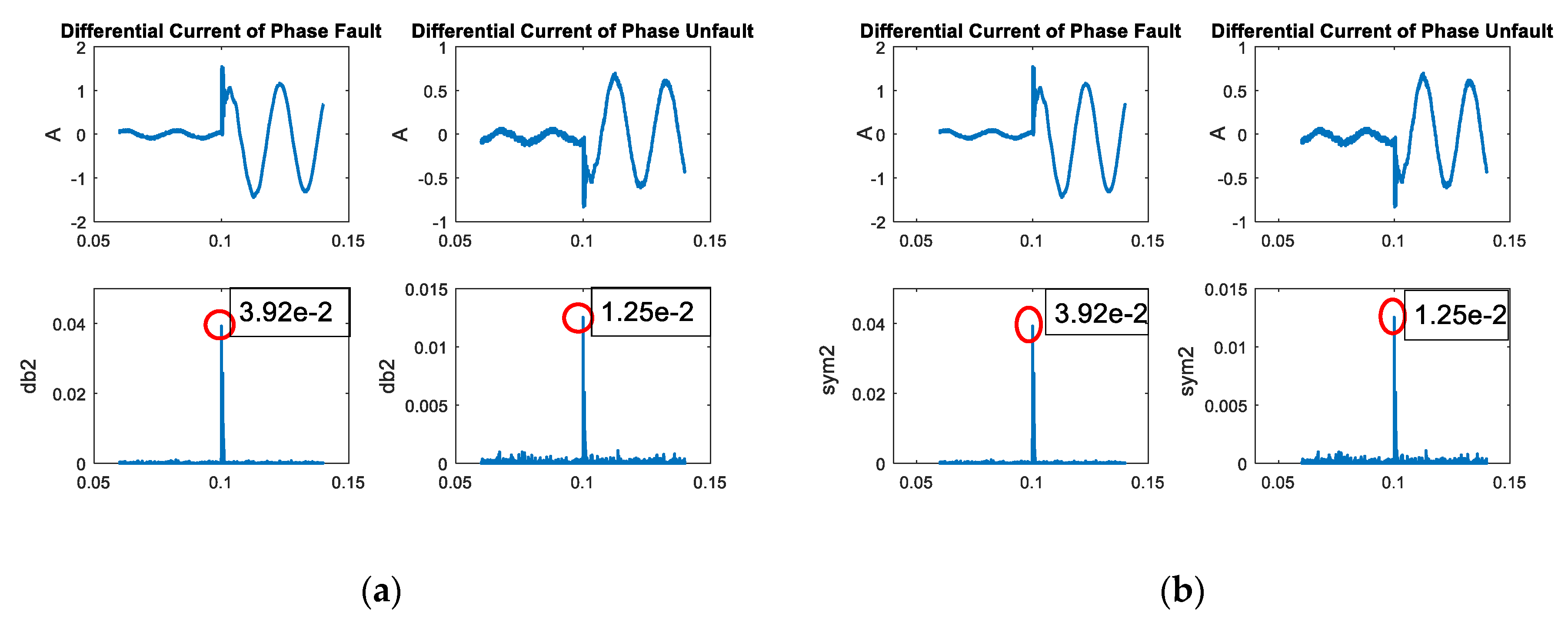
The four different mother wavelets were used to decompose the current signals to obtain the coefficient value from the high-frequency component. The extraction from the DWT of a differential current showed that the coefficients of the internal faults changed more than those of the external faults. However, the results of the four mother wavelets were similar, as shown in
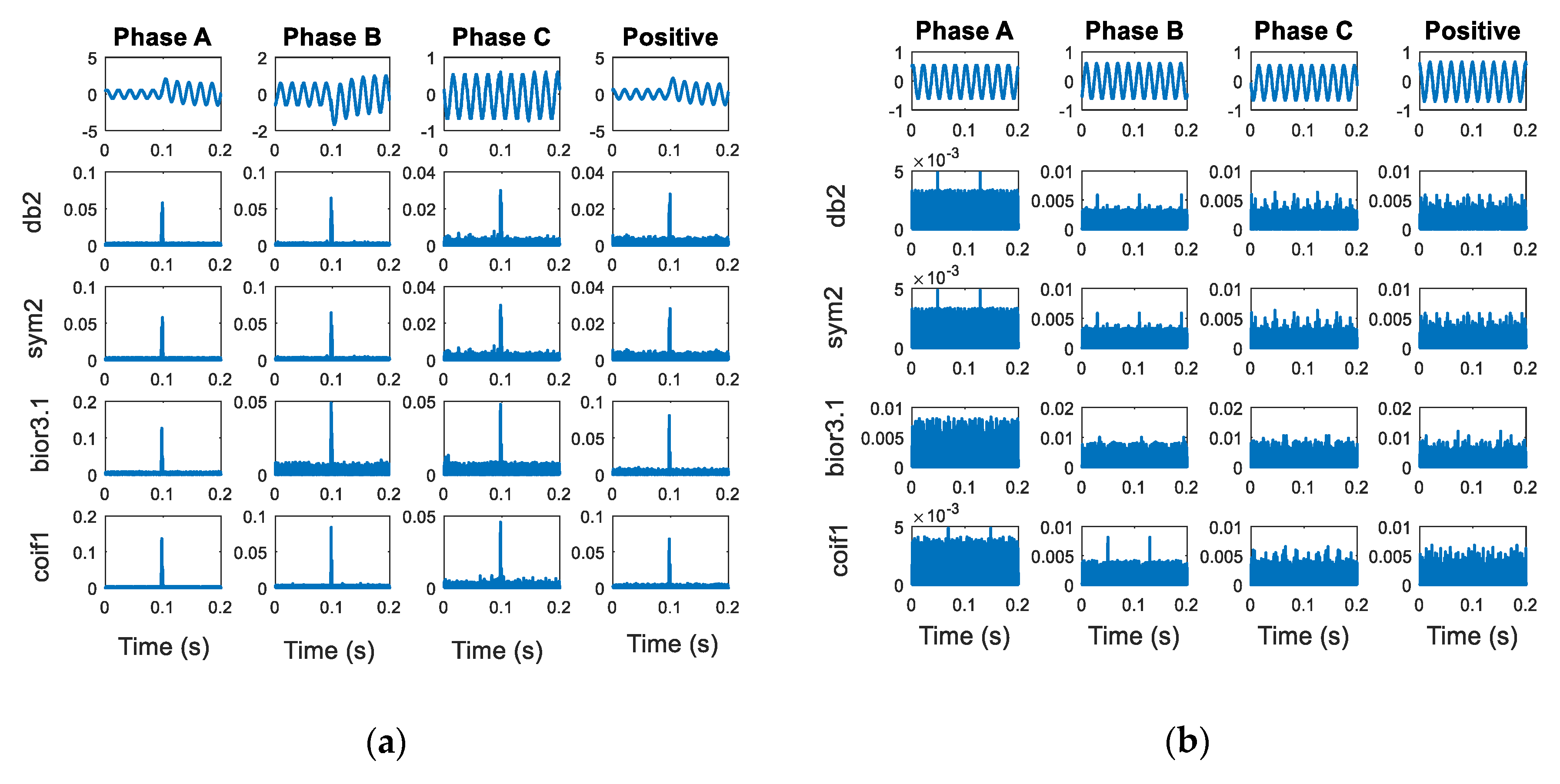
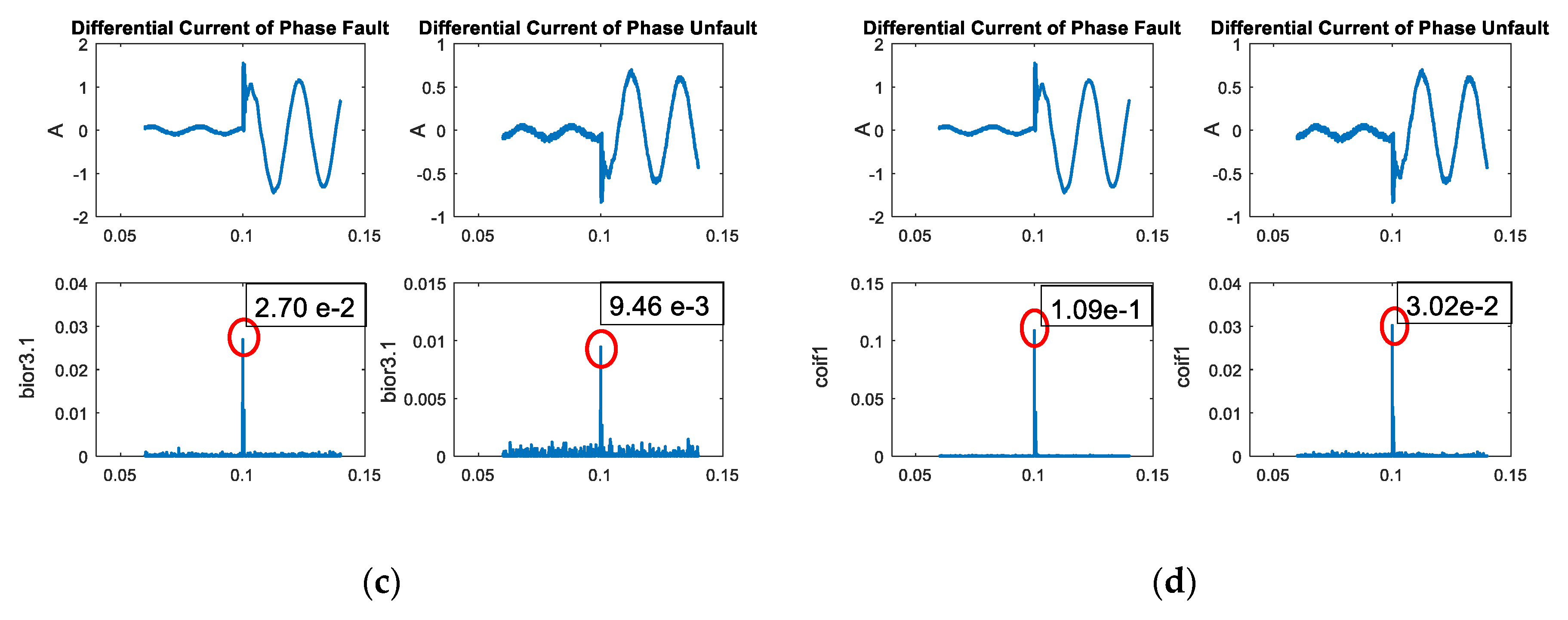
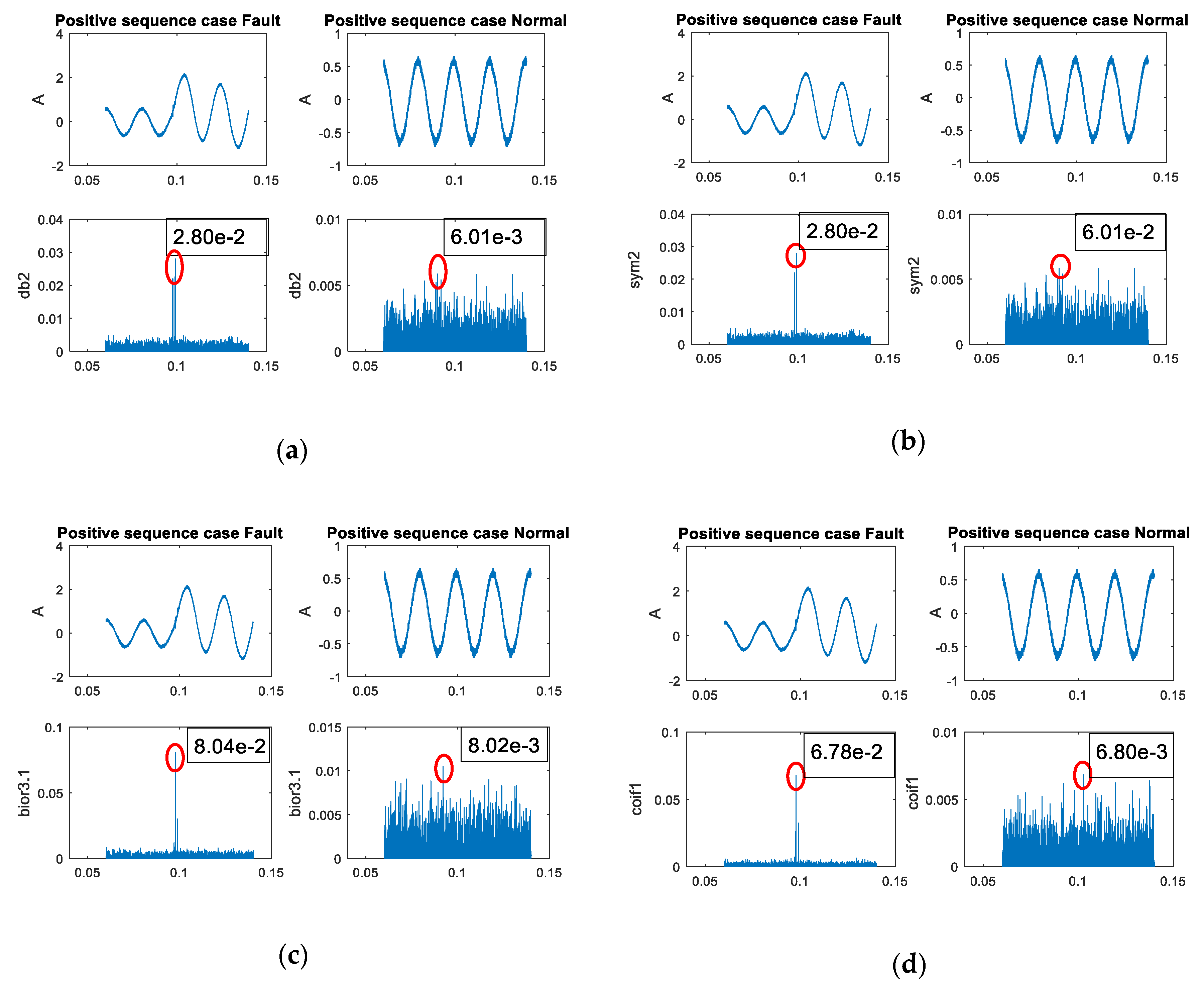
Figure 6. This characteristic was used to design the condition in a fault classification algorithm for relay 1 (transformer). External faults can be analyzed by using coefficients of transmission line systems. The coefficient characteristics between faulty and normal conditions when applied different mother wavelets are shown in
Figure 7. The extraction from the DWT of three-phase and positive sequence signals showed a similar trend with the fault condition having a higher coefficient than the normal condition. However, there was a difference in the coefficient value between different mother wavelets. The above behavior was used to design algorithms for fault classification.
The algorithm was operated by using the maximum coefficients, as shown in
Figure 8, for the transformer (relay 1) and
Figure 9 for the transmission line (relay 2). From
Figure 8 it can be seen that the result from DWT of differential current in scale 2 provided a higher maximum coefficient during the transient condition compared to the normal condition. In
Figure 9, a similar trend was also shown with the maximum coefficient from scale 2 in the case of an external fault higher than the normal case. The normal case only consisted of noise due to no significant transient state in the signal. This characteristic was used to indicate fault status, and the different mother wavelet provided different maximum coefficient values, which could impact the design algorithm.
5. Results
The results from the applied faulty classification algorithm on obtaining a signal from the experimental setup in the case of a fault on the transmission line and transformer is shown in
Table 2 and
Table 3, respectively. From the table, it can be seen that the coefficient values were different when different mother wavelets were used. If the coefficients of the wavelet transform were in accordance with the conditions in
Figure 9, the faults inside the transformer would be detected under condition 1, while the faults occurring in the external transformer would be detected under condition 2. For this reason, the first case was an internal fault. By considering the coefficients of relay 1 (Daubechies (db2)), the faults that occurred in phase attained maximum values, and the unfaulted phases also attained maximum values. Both values had coefficients that were larger than 5 × 10
−3, while the coefficients under normal conditions were smaller than 5 × 10
−3, as shown in
Figure 7a. Thus, the coefficients changed more than five times, and hence, an internal fault had occurred. The four mother wavelets exhibited the same behavioral characteristics of the coefficients. For the case of external faults, the faulted phases attained maximum values, and the unfaulted phases also attained maximum values. If these coefficients were smaller than 5 × 10
−3, external faults would occur. For fault classification with relay 2, positive sequences (Daubechies (db2)) were detected, which attained maximum values. Its coefficients were larger than 1 × 10
−2, and the pre-fault coefficients were smaller than 1 × 10
−2, as shown in
Figure 7a. By considering the coefficients, they changed more than two times, and therefore, there were faults in the electrical systems. Additionally, all four mother wavelets provided similar results. For all data, these algorithms could discriminate the fault types with an average accuracy of 97.75%. The mother wavelet types of db2, sym2, and coif1 provided the highest accuracy at 98.65%, and the mother wavelet type of bior31 had the lowest accuracy at 95.05%, as summarized in
Table 3.
6. Conclusions
This paper illustrates the importance of the mother wavelet for fault classification in electrical systems. When faults occur in transmission line systems and transformers, the coefficients in three phases and a positive sequence are detected. The behavior of the coefficients is dependent on the fault type, fault angle, and fault position. Phase faults have higher coefficients than phase unfaults. In addition, fault conditions can be detected by a positive sequence.
The mother wavelets, i.e., Daubechies (db), symlets (sym), biorthogonal (bior), and Coiflets (coif), are used to compare the coefficient values and behaviors.
Figure 5,
Figure 6,
Figure 7 and
Figure 8 show the coefficient values and behaviors. Each mother wavelet has a similar behavior, but its value is not the same. The same behavior can be obtained by different fault classification algorithms in data simulation, as shown in
Figure 9. The data are divided into three parts: 1. algorithm design—50% (888 data), 2. data testing—25% (444 data points), and 3. case study—25% (444 data points).
For the case study of the different mother wavelets, the accuracy of the results is summarized in
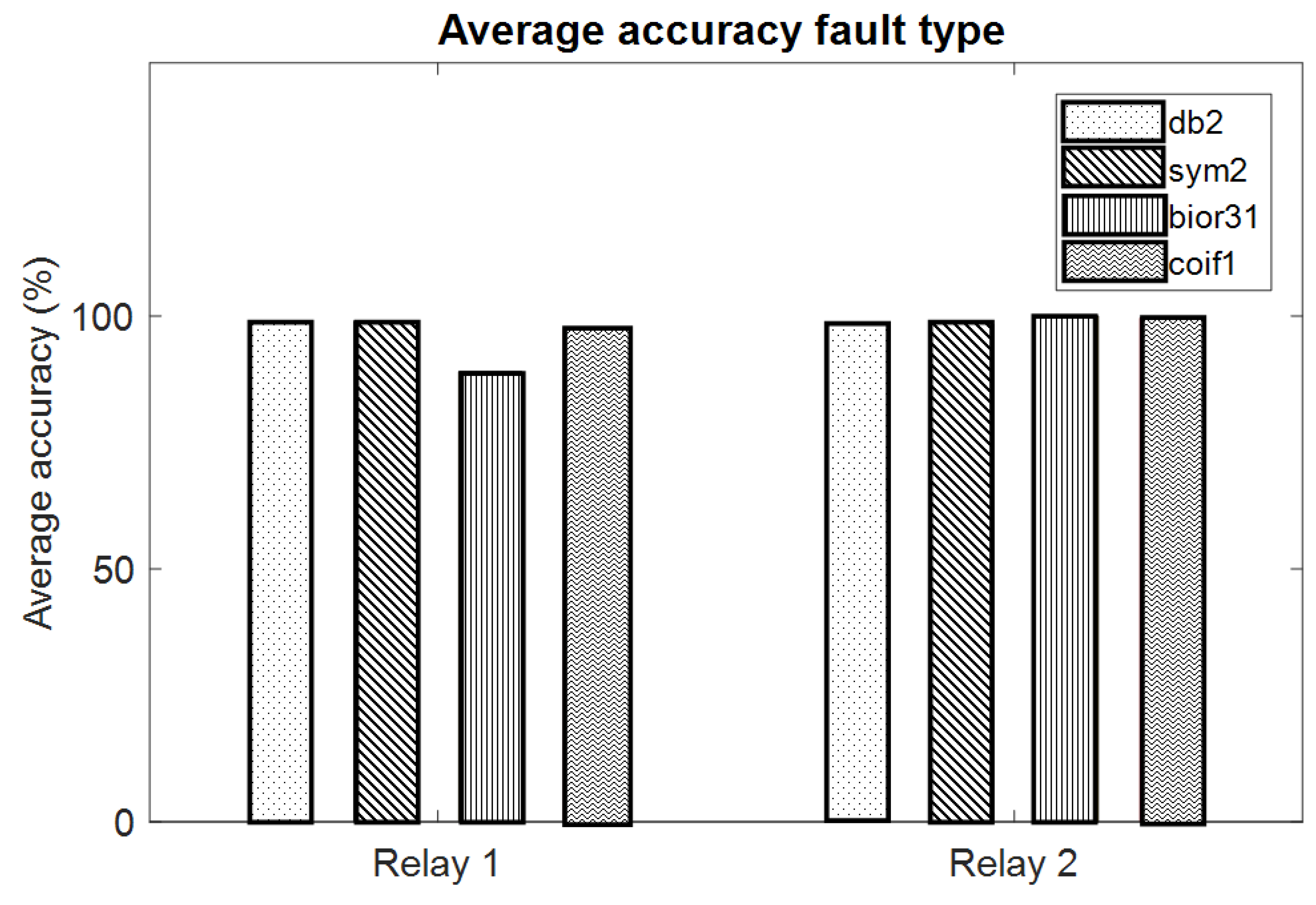
Table 3. The faults in the case study are discriminated by using the proposed algorithm. It is found that there is an average accuracy of internal fault detection (relay 1) of 96.12% and of external fault detection (relay 2) of 99.07%. The mother wavelet types of Daubechies (db2) and symlets (sym2) provide the highest accuracy under condition 1, while the mother wavelet type of biorthogonal (bior3.1) provides the highest accuracy under condition 2, as shown in
Figure 10.
The results from the study illustrated the performance of different mother wavelets on the fault classification algorithm. The different mother wavelets provide a different level of accuracy on the fault classification on a transformer, while they do not show a significant impact on fault classification in the transmission line. Thus, this mother wavelet is also one of the factors that must be considered in order to select the suitable mother wavelet for an application. Future work will broaden the suitable mother wavelet selection on other applications and to test the performance of the fault classification algorithm on different power system topologies to verify its application.


