Robustness Analysis for Multi-Agent Consensus Systems with Application to DC Motor Synchronization


1
Department of Electrical and Electronics Engineering, Instituto Tecnológico de Nuevo Laredo, Tecnológico Nacional de México, Nuevo Laredo, Tamaulipas C.P. 88000, Mexico
2
Electronics Department at U.A.M. Reynosa-Rodhe, Universidad Autónoma de Tamaulipas, Reynosa, Tamaulipas C.P. 88779, Mexico
3
Institut Pascal, Université Clermont Auvergne, CNRS, SIGMA Clermont, F-63000 Clermont-Ferrand, France
4
Sorbonne Universites, UTC, CNRS, UMR, 7253 Heudiasyc, France
5
UMI LAFMIA 3175 CNRS-CINVESTAV, Ciudad de México C.P. 07360, Mexico
*
Author to whom correspondence should be addressed.
†
These authors contributed equally to this work.
Appl. Sci. 2020, 10(18), 6521; https://doi.org/10.3390/app10186521
Submission received: 1 August 2020
/
Revised: 14 September 2020
/
Accepted: 15 September 2020
/
Published: 18 September 2020
(This article belongs to the Special Issue Multi-Agent Systems 2020)
Abstract
:DC motor speed synchronization is a critical problem in industrial and robotic applications. To tackle this problem, we propose to use a multi-agent consensus-based control scheme that guarantees the convergence of the DC motor speeds to either fixed or time-varying reference. A detailed robustness analysis considering parametric uncertainty and time delay in the multi-agent system is performed to guarantee the consensus on the speed of DC motors in actual practice. The results obtained concerning the robustness analysis allowed us to implement experimental tests on a three-motor system using a wireless communication system to achieve satisfactory performance.
1. Introduction
Multi-agent coordination control has been a research field of interest during the last few decades. A wide variety of multi-agent control methods can be found in the literature. These control approaches are classified as (a) virtual structure [1], where each agent is considered a component of a bigger structure; (b) behavioral control [2], which deals with conflicting tasks such as obstacle avoidance and move to goal, for example; and (c) leader–follower [3,4], where one of the agents works as a group leader and the others are designated as followers. The consensus is one of the most studied strategies to control multi-agent systems [4,5,6,7], and its applications include power systems [8], robotics [3,9], flight formation control [10], to mention a few.
Arguably, the most common actuator in robotics and industrial applications is the DC motor. It is well known that motor synchronization plays an important role in the quality of manufactured products. For example, in rolling mill machines, the conveyor belt’s tension must lie in an allowable tension to guarantee the thickness of the rolled steel [11]. As discussed in [12], many manufacturing processes require coordinated motion of two or more motion axes to achieve the desired performance, e.g., CNC machines, paper machines. Poor motor synchronization in such industrial applications would result in low-quality products that might be considered unusable in the worst case. The problem of designing control algorithms for motor synchronization has been considered in different research works. In [13], the authors presented some results on the synchronization of two motors’ speed using the leader–follower approach, where leader speed was used as a reference for the follower system, and the error was controlled by an LQR controller. A control scheme based on an adaptive sliding mode control technique was employed into the synchronization of the control system for four motors in [14]. In [15], a synchronization control strategy of multiple induction motors was proposed. The approach is based on an adjacent cross-coupling control structure, and then it can use a total sliding mode control method. A stator flux regulation method is used in [16] to apply an adaptive time-delay feedback control and the direct torque control to synchronize the chaotic speed of induction motors in a master–slave scheme. Three common synchronization methods for chaotic systems, namely an SMC control, a PI control, and an adaptive controller, were used in [17] to synchronize two brushless DC motor models in a master–slave configuration and were compared by using well-known performance indices.
Recently, the theory and applications of robust control in the presence of uncertainty and time delays have been addressed in the literature using a variety of control approaches [18,19,20,21], for example. The problem of the robustness of a multi-agent consensus control in the presence of uncertainty and time delays has been studied using various approaches [22,23,24,25]. In [22], a robust controller using algebraic Ricatti equations is presented. The agents are assumed to have linear dynamics, while uncertainty is treated as additive perturbations, which are assumed to be stable and bounded. Sliding mode control is proposed in [23] to deal with uncertainty as additive perturbations in a leader–follower multi-agent system. In a similar way than [22], it is assumed that additive perturbation is stable and bounded. In [24], a stochastic Lyapunov function to solve the consensus-seeking problem in networks where the agents can only obtain noisy measurements of its neighbor’s state is proposed. In these previously mentioned papers, dynamic uncertainty is considered, which is introduced to the system as an additive disturbance, and, in other cases, it is additive noise in contrast to this paper where uncertainty is considered in each of the parameters. A parametric uncertainty-based approach is proposed in [25]; here, the multi-agent system is transformed into a controllable form where the state matrix’s coefficients are assumed to be uncertain. Then, the maximal input’s time delay for which the multi-agent system stability is guaranteed is determined using the value set method. Here, an assumption is made in the multi-agent system to achieve the particular structure that allows for using the value set tool in contrast with our paper where that assumption is not made.
In this paper, we present a multi-agent consensus-based control scheme to synchronize the speed of DC motors. Unlike the methods discussed above, it can control multiple motors. In addition, in the multi-agent scheme, the motors are synchronized first to reach the consensus and then follow the reference, unlike the parallel or master–slave scheme. In this work, the leader’s control is based on the center of the state’s mass and the motors’ speed; thus, the response depends on all speeds, making the transient smoother. Previous to experimentation, an in-depth analysis was carried out in the system’s robustness to guarantee the proper function of the multi-agent system; that is, the tolerance to phenomena not considered in the mathematical model. First, uncertainty limits that may be withstood by the closed-loop multi-agent system are calculated in the model parameters. Then, time delay is added to the system, and the maximum value it can withstand is computed; both calculations are performed without losing the stability property. The above provides the confidence to apply the control strategy for synchronizing the speed of the three DC motors, which is perfectly validated with the experimental results presented at the end of this work.
This paper’s organization is as follows: the modeling of the information flow among agents using algebraic graph theory is presented in Section 2. The DC motor dynamic model and a control law based on multi-agent consensus control developed for DC motor speed synchronization are presented in Section 3. In Section 4, the robustness analysis of the multi-agent system in the presence of uncertainty and time delays is presented. In Section 5, experimental results are discussed. Finally, conclusions and future work are presented in Section 6.
2. Multi-Agent Consensus System Preliminaries
As discussed in [6], information exchange among agents is a necessary condition for multi-agent consensus. Such information exchange is often modelled using graph theory [6,26,27]. Then, in this section, some preliminary results on graph theory and forced multi-agent consensus are presented.
2.1. Graph Theory
A graph is a pair which consists of a set of nodes and a set of edges on . Every link between a pair of nodes (, ) is called an edge, e∈. A graph is said to be bidirectional if nodes and can get information from each other, i.e., (, ) (, ) . A graph is called digraph if the information between nodes only flows from node to . Thus, information exchange between agents can be modeled as a digraph but also as an undirected graph. A graph is said to be balanced if its in-degree (the number of communication links arriving at the node) is equal to its out-degree (the number of communication links leaving the node). A graph is connected if, for every pair (, ) of distinct vertices, there is a path from to . A connected graph allows the communication between all agents through the network. This leads us to the fact that a graph has a spanning tree if and only if is connected [27]. We assume that every communication link (, ) has a gain (weight) . A matrix representation of the information flow among agents can be obtained using Laplacian matrix. The definition of the Laplacian matrix is where and for and is the set of neighbors of the agent.
2.2. Multi-Agent Forced Consensus Control
Let us consider the following multi-agent system:
where is the state and is a forced consensus control strategy given by
where is a positive gain and is defined as follows:
Then, system (1) can be rewritten:
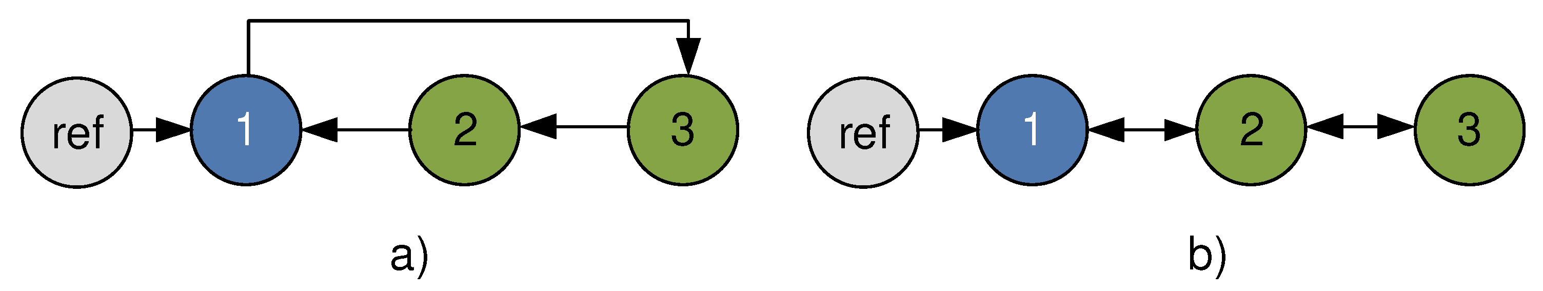
where are the output and input vectors and is the Laplacian matrix of , the multi-agent information graph. Notice that, without loss of generality, agent 1 can be designated as the leader agent with access to the reference as shown in Figure 1. The leader control law considered here is based on the center of mass (average) of the states [4]
where is a positive gain, N is the number of agents in the multi-agent system, and and are the desired state center of mass and the calculated system state center of mass, respectively.
2.3. Information Flow Topology
The information flow between agents is defined by the employed topology. In [4], it is stated that cyclic and chain topology, shown in Figure 1, can be combined to model all kinds of complex multi-agent information flow topologies. It is important to recall that the forced consensus of multi-agent systems of arbitrary length communicating over networks with cyclic and chain topologies are controllable and observable. Details on controllability and observability properties of leader-based multi-agent systems can be found in [4].
The state space representation of a multi-agent system with cyclic topology is the following:
The state space representation of a multi-agent system with the chain topology is the following:
3. DC Motor Speed Consensus Control
The DC motor model employed in this work was presented in [13]
with
where and . is the motor angular velocity. Motor parameters employed in (9) are: is the motor armature resistance, is the motor back-emf constant, is the motor current-torque constant, is the gear ratio, is the motor efficiency, is the gearbox efficiency, is the motor shaft moment of inertia, is the load moment of inertia, is the viscous friction on the motor shaft, and is the viscous friction on the load shaft. The final model is obtained from (9)
where , , , and , which is designed to compensate the dynamics as follows:
where is the control law obtained in the following sections.
Although multi-agent consensus control can be used to synchronize any number of DC motors, for simplicity, we illustrate the application of the consensus control on a three DC-motor system communicating over a network with cyclic topology.
3.1. Three Agents Cyclic Topology
The particular case of a three agents system with a cyclic topology, as in Figure 1a, is analyzed below. Thus, for this case, Equation (1) simplifies to
Now, according to the desired reference characteristics, we consider the situations of fixed reference and time variant reference.
3.2. Fixed Reference
The resulting matrix has an eigenvector . Pre multiplying (14) by ,
The center of mass of the states is
Then, we take the leader control law (5) with
where is the desired center of mass value and is a constant. By substituting (17) in (15), we obtain
From (19), it is possible to see that , and converges to .
Remark 1.
It is worth to recall that since the leader control is based on the center of mass of the agent’s states, the general case for DC motor synchronization can be achieved by using control law (5).
3.3. Time Varying Reference
When a time varying reference is considered, it is necessary to include additional controls in all the agents besides the leader
where
by substituting (21) in (20), we obtain
again, by adding (22a), (22b), and (22c), we obtain
Equation (23) shows that as . From Equation (22b),
then as . Finally, from (22c),
so we can see that as .
To generalize this procedure for N motors, modify (20) as follows:
where is the same as in (21a), for and , considering a cyclic case.
4. Robust Consensus Analysis
Equation (14) is the mathematical model of the consensus system for the particular case of three DC motors considering a cyclic topology; however, it is worth noting that the method presented in this section is valid for any topology that could be considered. In real life, it does not exist a perfect mathematical model that represents the dynamic performance of a physical system, so different areas of control theory, such as robust control, seek to compensate for modeling errors. Robust control considers the uncertainty in the mathematical model, taking it into account in the analysis stage so that the results are closer to reality than in the case when uncertainty is not considered. The state of the multi-agent system (14) represents the information exchange of the variables that must be synchronized, which, in our case, are the speeds of the DC motors. For the above, it is essential to use sensor devices frequently affected by the measurement noise. This phenomenon is modeled considering parametric uncertainty in the coefficients of the Laplacian matrix, as shown below, see [29]
where
and Q is defined as
the sets defined as in (28) are generally called boxes because of the geometric shape they have. On the other hand, manipulating Equation (27), the following equation can be obtained:
the vectors and are the nominal and uncertain parameters of the multi-agent system, respectively. Their structure is as follows:
the new way of representing the parametric uncertainty in (29), allows for describing the system (27) as follows:
As we can see in the above equation, the uncertainty was only considered in the multi-agent system because our main objective was to establish the consensus in this system and achieve synchronization in the DC motors’ speed. The uncertainty in the DC motors’ mathematical model was treated independently through the control law applied to each motor (11).
4.1. Robust Consensus for the Multi-Agent System
In this section, the Lyapunov method is going to use to find the robustness margins of the multi-agent system. We will start by defining the following Lyapunov function taking into account the representation of the multi-agent system shown in (30):
where, as stated in the Lyapunov method, the matrix P is a real symmetric positive definite matrix. Taking as in (31), the derivative of V along the trajectories of the multi-agent system is given by
Now, considering the control law as defined in (17), it is possible to obtain the following equation:
The term in Equation (32) represents an inner product so the Cauchy–Schwarz inequality can be applied to obtain the following expression, see [30]
Here, is the upper bound of uncertainty and are the eigenvalues of the matrix P. When we replace the previous terms in (32), the following condition is obtained:
where Q is a real symmetric positive definite matrix and satisfies the following equation:
Finally,
Therefore, the condition to ensure the stability property of the uncertain multi-agent system (30) is the following:
In the previous equation, it can be seen that the robustness margin is a function of the Q and P matrices that solve the Equation (33). Now, considering the closed-loop multi-agent system from (19)
and defining , the solution of Equation (33) is as follows:
Therefore, it can be noted that the uncertainty tolerated by the closed-loop multi-agent system must be . This implies that the equivalent uncertainty supported by the system is equal to in each parameter of the Laplacian matrix, that is,
where and . It is possible to appreciate this robustness margin in the experimental tests that will be presented later.
4.2. A Practical Example of Computing the Time Delay Margin in Communication between Agents
A fundamental aspect to achieve the consensus of multi-agent systems is communication between agents, which is why it is important to consider all the possible phenomena that occur in this process. An important point is the time delay that exists when one agent sends messages to another; see [5,6]; this can be represented by
where
The structure of the multi-agent system previously presented is due to the topology selected in Section 3.1, and it is important to note that the element of the matrix Ar(3, 1) is equal to 1.25 because uncertainty was considered in that parameter. However, it could have been considered in all the matrix terms (37) without affecting the methodology. The calculations would be similar to those made for this particular case of the DC motor synchronization. Now, considering the control law from (17), the following closed-loop multi-agent system is obtained:
where
Once the structure of the system is well defined, the fundamental problem will be to calculate the maximum time delay that the multi-agent system supports without the stability property being lost. It is well known that the property of stability of (39) is determined by the roots of the following characteristic equation; see [31]
Once this equation is developed, it represents functions called quasipolynomials that have the following form:
where
The multi-agent system (39) is stable if and only if the following condition is satisfied:
where denotes the set of complex numbers with real part greater or equal to zero. Like an extension of the stability concept, the quasipolynomials that satisfy the previous condition are called stable quasipolynomials. Due to difficulty in determining the roots of quasipolinomial functions, we will define the following associated polynomials:
These associate polynomials have an important relation between their roots: suppose that for some value of ; then, is a root of the characteristic equation for some value of if and only if is a root of for some value of . This relation that exists between and is obtained from a transformation that is carried out in the exponential function that represents the time delay; see [32], while the relation between T and is determined as follows (see [33]):
where ; the set of W is defined as follows:
in the case of the multi-agent system (39), the associated polynomial is the following:
where
Now, define the polynomial associated Hurwitz matrix as follows:
and let the polynomial associated with and consider as the Hurwitz matrix in the functioning of of the associate polynomial ; if is stable for , then is stable for all if and only if
This result shows stability conditions for any time delay; when this happens, it is said that the system is stable independent of the delay. However, our goal is to determine the maximum delay that the multi-agent system can support without losing the stability property. To do this, it is necessary to compute the values of T where the determinant of the Hurwitz matrix becomes zero and using (47) and (48) compute the time delays for which the system loses the stability property. Carrying out the corresponding computation, we get the values of T that make the determinant of the Hurwitz matrix (51) zero; these are and and their corresponding . These, in turn, are used to compute and ; thus, the maximum delay supported by the multi-agent system is s. The robustness analysis performed in this section guarantees that adequate performance is obtained in experimental testing of the DC motor synchronization.
5. Experimental Results
The agent speed consensus control addressed in Section 2 was implemented by using a Bluetooth wireless communication system and an embedded microcontroller-based control platform, as shown in Figure 2. This platform consists of three identical modules whose elements are: a DC motor managed by a dual-core ARM Cortex-A9 embedded microcontroller system, with the ability to be programmed via WiFi, a Bluetooth transmitter, and a receiver (115,200 baud), as well as an encoder to measure motor speed, with a sampling frequency of 25 samples per second. Each motor has a load consisting of a wheel. The control algorithm was programmed using LabVIEW®. Before the tests, the WiFi communication was used to configure the controllers parameters, but, during the tests, it was only used to send the reference value from the computer to the leader controller. The gains and were chosen to have an underdamped response. Note that while controllers 2 and 3 need one speed state information via Bluetooth, the controller 1, the leader, needs to have all speeds to calculate the center of mass. Approximate motor parameter values are shown in Table 1. It is important to note that, in this system, there may be several sources of uncertainty, namely motor parameters, measurement noise, and transmission delays. A schematic diagram of the multi-agent system is shown in Figure 2, and the experimental implementation is presented in Figure 3.
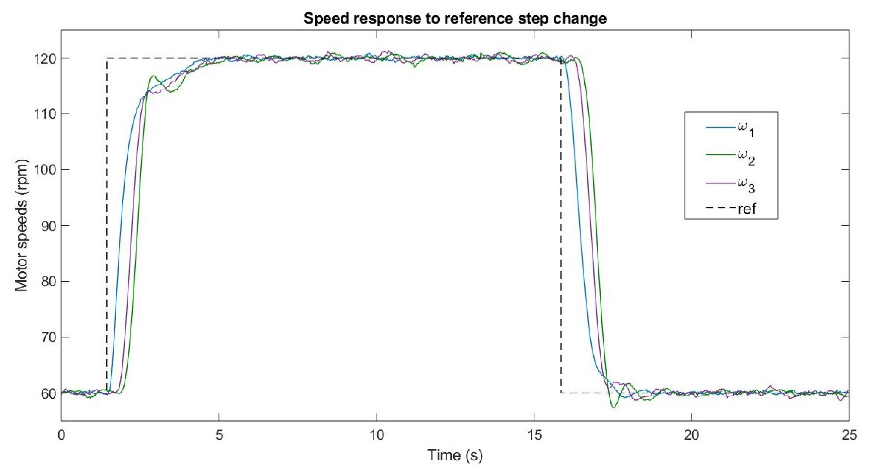
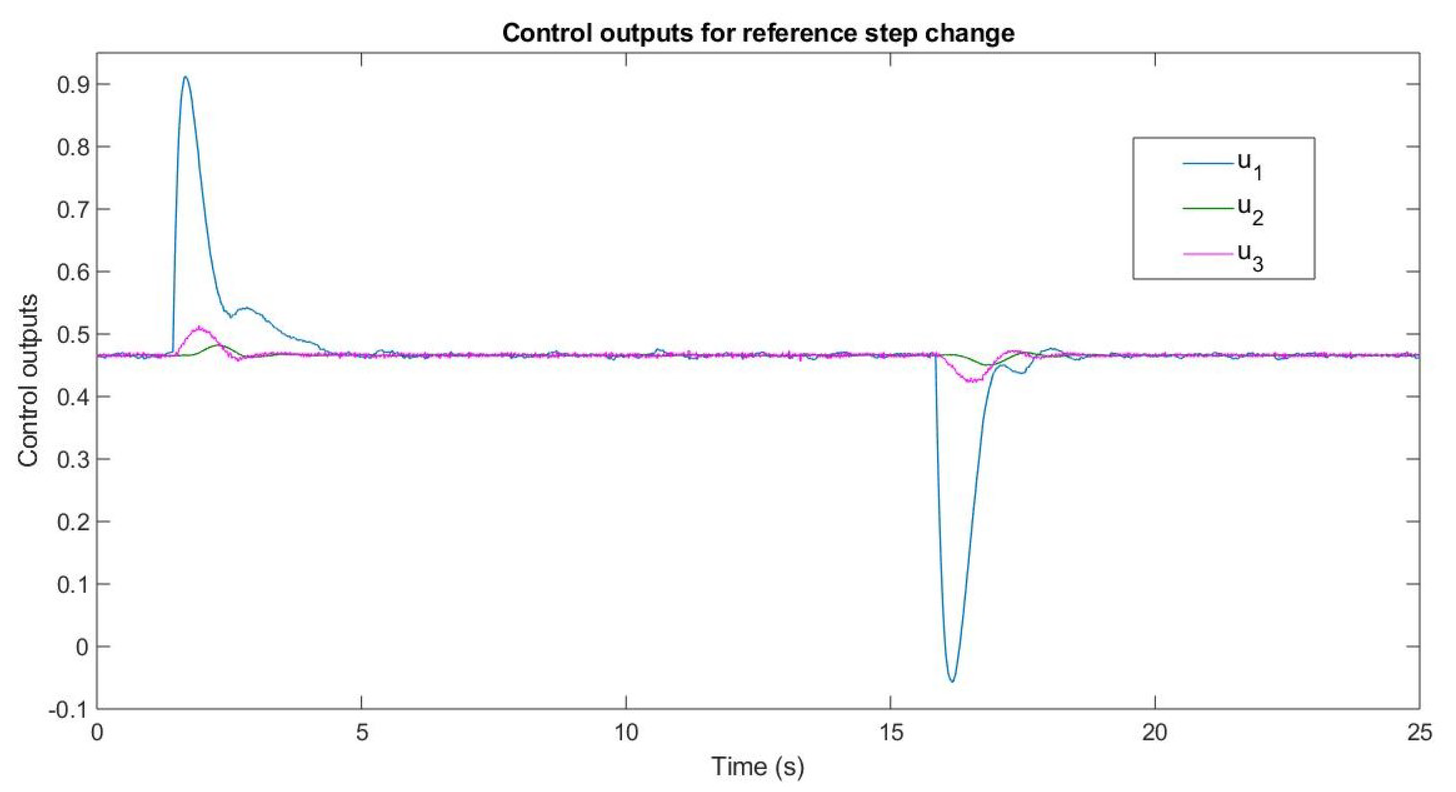
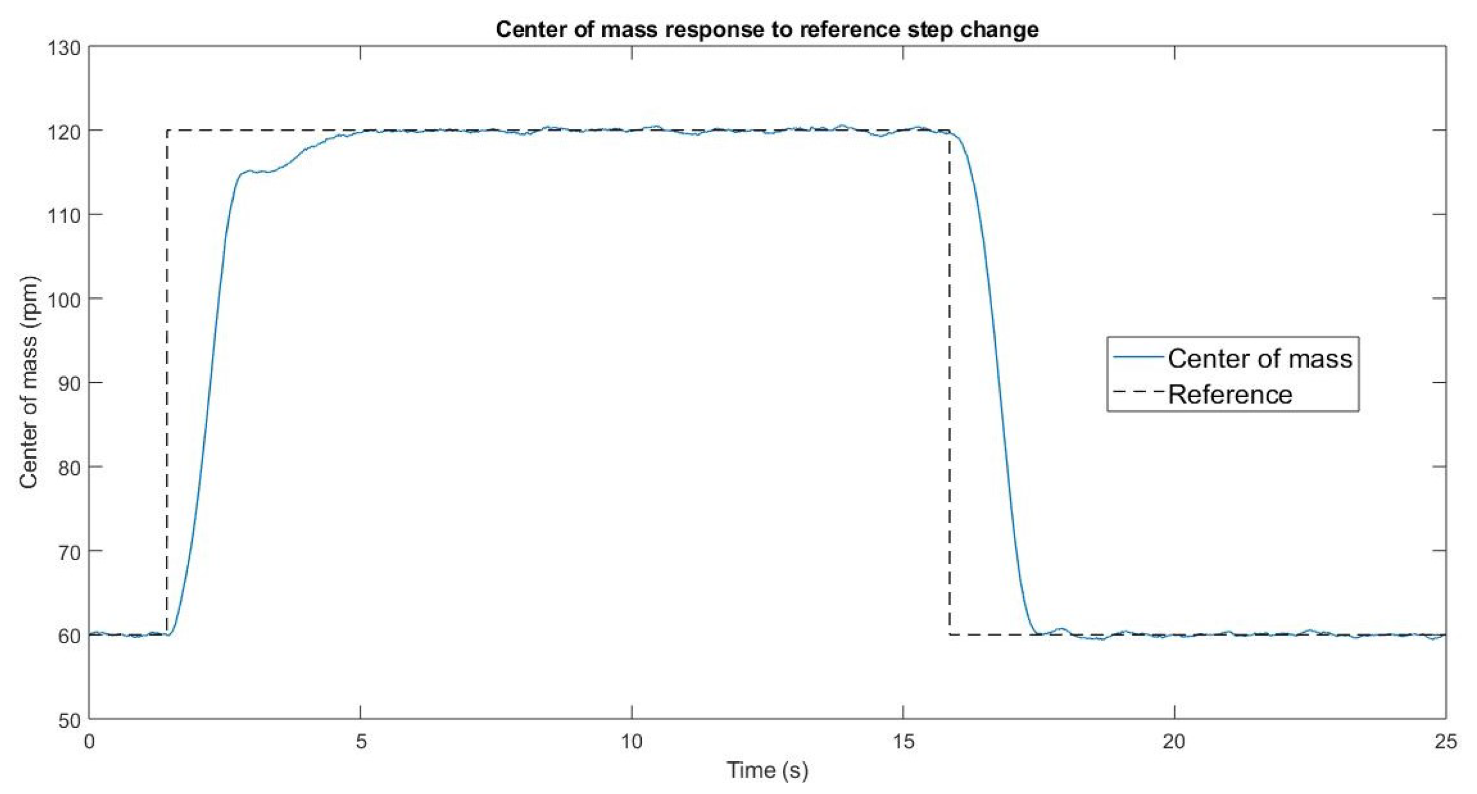
The tests consisted of a step reference change and a sinusoidal reference change, . The response of the DC motor speeds ( rpm, rpm and rpm) and controls to a reference step change are shown in Figure 4 and Figure 5, respectively. It is possible to note that the leader control has a bigger transitory because it is responsible for carrying the system to the reference; the other two controls carry the states to the center of mass. The behavior of the center of mass is plotted in Figure 6, where the center of mass is very close to the reference during stationary state and smoother than the speeds, acting as a low pass filter. This variation, of approximately 0.5 rpm, is mainly due to the encoder used to measure speed. Figure 7, Figure 8 and Figure 9 show the response, control outputs of the motor system, and the center of mass with a time-varying reference ( rpm, rpm and rpm). The synchronization of angular speeds is appreciated under reference step change and sinusoidal reference. Observe that small errors appear when using time-varying references, due to the propagation delay of the reference over the wireless communication system and the states, working as uncertainty, but is not enough to avoid synchronization.
6. Conclusions and Future Work
In this article, an application of a control methodology that uses a multi-agent consensus theory was presented. The convergence of the states to both a fixed and a time-varying reference was demonstrated on a three-agents system with cyclic information flow topology. This methodology was applied in order to synchronize the speed of three DC motors. Through a robustness analysis of the uncertainty of the parameters of DC motors and the delays in communication between agents, the consensus was ensured. In addition, experimental results on a three DC motor system with a wireless communication system were presented. Most of the reviewed works presented just two motors. It was implemented by using a Bluetooth wireless agent communication system and an embedded micro-controller based control platform. It was noticed that the proposed control approach allows us to synchronize the multiple DC motor system. The small agent consensus error concerning the desired reference is due, besides the motor dynamics, to wireless communication systems, and the information flow topology.
From the information above, we identify three different research lines that may be addressed as future work; the first is to perform an independent robustness analysis in each of the parameters of the Laplacian matrix prioritizing the parameters that may present most variation. The second research line is to consider in the analysis of the time delay system a higher number of parameters with uncertainty since this paper only considers one of them. Regarding the latter, it is clear that the maximum time delay that the close loop system may withstand without losing the stability property will be smaller than the one obtained when considering only one parameter. Finally, another future work is to perform experimental testing considering different topologies of information exchange such as chain topology or balances graph topology, adapting the experimental platform for this purpose.
Author Contributions
Conceptualization, D.O., G.R., J.A.G., and R.L.; methodology, G.R. and J.A.G.; software, D.O., G.R., and J.A.G.; validation, D.O.; formal analysis, D.O., G.R., J.A.G., and R.L.; investigation, D.O., G.R., J.A.G., and R.L.; resources, D.O., G.R., J.A.G., and R.L.; writing—original draft preparation, D.O., G.R., and J.A.G.; writing—review and editing, D.O., G.R., and J.A.G.; visualization, D.O., G.R., and J.A.G.; supervision, G.R. and J.A.G.; project administration, G.R.; funding acquisition, D.O. and G.R. All authors have read and agreed to the published version of the manuscript.
Funding
The work of Gerardo Romero was supported by Universidad Autónoma de Tamaulipas, under grants PROINNOVA-2018-250105, PROINNOVA-2018-250586, PROINNOVA-2018-250540, PROINNOVA-2018-250113, PROINNOVA-2018-250117, PROINNOVA-2018-250160, and PROINNOVA-2018-250255.
Acknowledgments
Daniel Olivares appreciates the support and use of facilities of the Tecnológico Nacional de México—Instituto Tecnológico de Nuevo Laredo.
Conflicts of Interest
The authors declare no conflict of interest.
References
- Leonard, N.E.; Fiorelli, E. Virtual leaders, artificial potentials and coordinated control of groups. In Proceedings of the 40th IEEE Conference on Decision and Control (Cat. No.01CH37228), Orlando, FL, USA, 4–7 December 2001; pp. 2968–2973. [Google Scholar]
- Arrichiello, F.; Chiaverini, S.; Fossen, T. Formation Control of Marine Surface Vessels Using the Null-Space-Based Behavioral Control. In Lecture Notes in Control and Information Sciences: Group Coordination and Cooperative Control; Springer: Berlin/Heidelberg, Germany, 2006; pp. 1–19. [Google Scholar]
- Chen, X.; Serrani, A. ISS-Based Robust Leader/Follower Trailing Control. In Lecture Notes in Control and Information Sciences: Group Coordination and Cooperative Control; Springer: Berlin/Heidelberg, Germany, 2006; pp. 75–91. [Google Scholar]
- Lozano, R.; Spong, M.W.; Guerrero, J.A.; Chopra, N. Controllability and observability of leader-based multi-agent systems. In Proceedings of the 47th IEEE Conference on Decision and Control, Cancun, Mexico, 9–11 December 2008; pp. 3713–3718. [Google Scholar]
- Olfati-Saber, R.; Fax, J.A.; Murray, R.M. Consensus and Cooperation in Networked Multi-Agent Systems. Proc. IEEE 2007, 95, 215–233. [Google Scholar]
- Ren, W.; Beard, R.W.; Atkins, E.M. Information Consensus in Multivehicle Cooperative Control. IEEE Control Syst. Mag. 2007, 27, 71–82. [Google Scholar]
- Guerrero, J.A.; Olivares, D.; Romero, G. Forced Bipartite Consensus for Multi-Agent Systems. In Proceedings of the 44th Annual Conference of the IEEE Industrial Electronics Society (IECON), Washington, DC, USA, 21–23 October 2018; pp. 2335–2340. [Google Scholar]
- Nagata, T.; Sasaki, H. A multi-agent approach to power system restoration. IEEE Trans. Power Syst. 2002, 17, 457–462. [Google Scholar] [CrossRef]
- Balch, T.; Arkin, R.C. Behavior-based formation control for multirobot teams. IEEE Trans. Robot. Autom. 1998, 14, 926–939. [Google Scholar] [CrossRef] [Green Version]
- Guerrero, J.A.; Lozano, R. Flight Formation of Multiple Mini Rotorcraft based on Nested Saturations. In Proceedings of the 2010 IEEE/RSJ International Conference on Intelligent Robots and Systems, Taipei, Taiwan, 18–22 October 2010; pp. 634–639. [Google Scholar]
- Chuang, C.W.; Haung, C.L.; Lee, C.D.; Kao, C.C.; Fung, R.F. Synchronization and tension control of dual motor systems via MIMO discrete pseudo model following integral variable structure control. Mech. Mach. Theory 2009, 44, 499–510. [Google Scholar] [CrossRef]
- Chiu, G.T.C.; Tomizuka, M. Coordinated Position Control of Multi-Axis Mechanical Systems. J. Dyn. Syst. Meas. Control 1998, 120, 389–393. [Google Scholar] [CrossRef]
- Guzey, H.C.; Dumlu, A.; Guzey, N.; Alpay, A. Optimal Synchronizing Speed Control of Multiple DC Motors. In Proceedings of the 4th International Conference on Optimization and Applications, Mohammedia, Morocco, 26–27 April 2018; pp. 1–5. [Google Scholar]
- Li, L.; Sun, L.; Zhang, S.; Yang, Q. Speed tracking and synchronization of multiple motors using ring coupling control and adaptive sliding mode control. ISA Trans. 2015, 58, 635–649. [Google Scholar] [CrossRef] [PubMed]
- Zhao, D.; Li, C.; Ren, J. Speed Synchronization of Multiple Induction Motors with Total Sliding Mode Control. Syst. Eng. Theory Pract. 2009, 29, 110–117. [Google Scholar] [CrossRef]
- Zhang, Z.; Chau, K.T.; Wang, Z. Chaotic Speed Synchronization Control of Multiple Induction Motors Using Stator Flux Regulation. IEEE Trans. Magn. 2012, 48, 4487–4490. [Google Scholar] [CrossRef]
- Kose, E.; Muhurcu, A. The Control of Brushless DC Motor for Electric Vehicle by Using Chaotic Synchronization Method. Stud. Inform. Control 2018, 27, 403–412. [Google Scholar] [CrossRef] [Green Version]
- Bhattacharyya, S.P. Robust control under parametric uncertainty: An overview and recent results. Annu. Rev. Control 2017, 44, 45–77. [Google Scholar] [CrossRef]
- Matusu, R.; Senol, B.; Pekar, L. Value-Set-Based Approach to Robust Stability Analysis for Ellipsoidal Families of Fractional-Order Polynomials with Complicated Uncertainty Structure. Appl. Sci. 2019, 9, 5451. [Google Scholar] [CrossRef] [Green Version]
- Sun, Y.-G.; Xie, S.; Xu, J.-Q.; Lin, G.-B. A Robust Levitation Control of Maglev Vehicles Subject to Time Delay and Disturbances: Design and Hardware Experimentation. Appl. Sci. 2020, 10, 1179. [Google Scholar] [CrossRef] [Green Version]
- Wu, L.; Zhao, R.; Li, Y.; Chen, Y.-H. Optimal Design of Adaptive Robust Control for the Delta Robot with Uncertainty: Fuzzy Set-Based Approach. Appl. Sci. 2020, 10, 3472. [Google Scholar] [CrossRef]
- Trentelman, H.L.; Takaba, K.; Monshizadeh, N. Robust Synchronization of Uncertain Linear Multi-Agent Systems. IEEE Trans. Autom. Control 2013, 58, 1511–1523. [Google Scholar] [CrossRef] [Green Version]
- Wang, X.; Li, S. Distributed finite-time consensus algorithms for leader–follower second-order multi-agent systems with mismatched disturbances. In Proceedings of the IEEE American Control Conference, Boston, MA, USA, 6–8 July 2016; pp. 2814–2819. [Google Scholar]
- Huang, M.; Manton, J.H. Coordination and Consensus of Networked Agents with Noisy Measurements: Stochastic Algorithms and Asymptotic Behavior. SIAM J. Control Optim. 2009, 8, 134–161. [Google Scholar] [CrossRef]
- Guerrero, J.A.; Romero, G.; Lozano, R. Robust consensus tracking of leader-based multi-agent systems. In Proceedings of the 2010 American Control Conference, Baltimore, MD, USA, 30 June–2 July 2010; pp. 6299–6305. [Google Scholar]
- Godsil, C.; Royle, G. Graduate Texts in Mathematics: Algebraic Graph Theory; Springer: Berlin, Germany, 2001. [Google Scholar]
- Mesbahi, M.; Egerstedt, M. Graph Theoretic Methods in Multiagent Networks; Princeton University Press: Princeton, NJ, USA, 2010. [Google Scholar]
- Guerrero, J.A.; Castillo, P.; Challal, Y. Trajectory Tracking for a Group of Mini Rotorcraft Flying in Formation. In Proceedings of the IFAC World Congress, Milano, Italy, 27 August–2 September 2011; pp. 6331–6336. [Google Scholar]
- Romero, G.; Guerrero, J.A.; Reyes, L.D.; Lozano, R.; Olivares, D. Robustness Margin for Leader-based Multi-agent Consensus Systems in Presence of Parametric Uncertainty. In Proceedings of the 44th Annual Conference of the IEEE Industrial Electronics Society (IECON), Washington, DC, USA, 21–23 October 2018; pp. 2625–2630. [Google Scholar]
- Luenberger, D.G. Optimization by Vector Space Methods; John Wiley & Sons, Inc.: New York, NY, USA, 1969. [Google Scholar]
- Romero, G.; Diaz, I.; Perez, I.; Guerrero, J.A.; Lara, D.; Rivera, J. New results on robust stability for differential-difference systems with affine linear parametric uncertainty. Int. J. Syst. Sci. 2013, 44, 14–22. [Google Scholar] [CrossRef]
- Thowsen, A. An Analytic Stability Test for a Class of Time-Delay Systems. IEEE Trans. Autom. Control 1981, 26, 735–736. [Google Scholar] [CrossRef]
- Thowsen, A. The Routh-Hurwitz Method for Stability Test for a Class of Time-Delay Systems. Int. J. Control 1981, 33, 991–995. [Google Scholar] [CrossRef]
Figure 1.
Information flow configuration: (a) cyclic topology; (b) chain topology. The gray circle represents the leader agent and white circles are followers.
Figure 1.
Information flow configuration: (a) cyclic topology; (b) chain topology. The gray circle represents the leader agent and white circles are followers.

Figure 2.
Experimental agent interconnection diagram.

Figure 3.
Three-motor synchronization experimental platform.

Figure 4.
Experimental speed consensus with a reference step change.

Figure 5.
Experimental control outputs with a reference step change.

Figure 6.
Experimental state center of mass with a reference step change.

Figure 7.
Experimental speed tracking using a sinusoidal reference.

Figure 8.
Experimental control outputs for each agent following a sinusoidal reference.

Figure 9.
Experimental center of mass of agents following a sinusoidal reference.


Table 1.
Motor parameters and values.
| 3.3 | Nm/(rad/s) | ||
| V/(rad/s) | Nm/A | ||
| 53 | 0.69 | ||
| 0.90 | |||
| Nm/(rad/s) |
© 2020 by the authors. Licensee MDPI, Basel, Switzerland. This article is an open access article distributed under the terms and conditions of the Creative Commons Attribution (CC BY) license (http://creativecommons.org/licenses/by/4.0/).
Share and Cite
MDPI and ACS Style
Olivares, D.; Romero, G.; Guerrero, J.A.; Lozano, R. Robustness Analysis for Multi-Agent Consensus Systems with Application to DC Motor Synchronization. Appl. Sci. 2020, 10, 6521. https://doi.org/10.3390/app10186521
AMA Style
Olivares D, Romero G, Guerrero JA, Lozano R. Robustness Analysis for Multi-Agent Consensus Systems with Application to DC Motor Synchronization. Applied Sciences. 2020; 10(18):6521. https://doi.org/10.3390/app10186521
Chicago/Turabian StyleOlivares, Daniel, Gerardo Romero, Jose A. Guerrero, and Rogelio Lozano. 2020. "Robustness Analysis for Multi-Agent Consensus Systems with Application to DC Motor Synchronization" Applied Sciences 10, no. 18: 6521. https://doi.org/10.3390/app10186521
Note that from the first issue of 2016, this journal uses article numbers instead of page numbers. See further details here.