VNF Placement for Service Function Chains with Strong Low-Delay Restrictions in Edge Computing Networks


Department of Information Technologies and Communications, Universidad Politecnica de Cartagena, E-30202 Cartagena, Spain
*
Author to whom correspondence should be addressed.
Appl. Sci. 2020, 10(18), 6573; https://doi.org/10.3390/app10186573
Submission received: 26 August 2020
/
Revised: 17 September 2020
/
Accepted: 18 September 2020
/
Published: 20 September 2020
(This article belongs to the Special Issue Novel Algorithms and Protocols for Networks)
Abstract
:Featured Application
Mapping of service function chains containing low-delay demanding virtual network functions into mixed micro data center/cloud data center edge computing scenarios, optimizing a multi-parameter cost.
Abstract
The edge computing paradigm, allowing the location of network services close to end users, defines new network scenarios. One of them considers the existence of micro data centers, with reduced resources but located closer to service requesters, to complement remote cloud data centers. This hierarchical and geo-distributed architecture allows the definition of different time constraints that can be taken into account when mapping services into data centers. This feature is especially useful in the Virtual Network Function (VNF) placement problem, where the network functions composing a Service Function Chain (SFC) may require more or less strong delay restrictions. We propose the ModPG (Modified Priority-based Greedy) heuristic, a VNF placement solution that weighs the latency, bandwidth, and resource restrictions, but also the instantiation cost of VNFs. ModPG is an improved solution of a previous proposal (called PG). Although both heuristics share the same optimization target, that is the reduction of the total substrate resource cost, the ModPG heuristic identifies and solves a limitation of the PG solution: the mapping of sets of SFCs that include a significant proportion of SFC requests with strong low-delay restrictions. Unlike PG heuristic performance evaluation, where the amount of SFC requests with strong low-delay restrictions is not considered as a factor to be analyzed, in this work, both solutions are compared considering the presence of 1%, 15%, and 25% of this type of SFC request. Results show that the ModPG heuristic optimizes the target cost similarly to the original proposal, and at the same time, it offers a better performance when a significant number of low-delay demanding SFC requests are present.
1. Introduction
Edge Computing (EC) [1,2,3] is considered as a key supporting technology for the emerging Internet of Things (IoT) and 5G networks. Computing services are shifted to the edge of the Internet ideally within one hop from mobile devices and other smart devices [4].
The traffic demands of existing services and, most importantly, new services such as Virtual Reality (VR), Augmented Reality (AR), public security, smart cities, or connected cars pose challenges to remote resource-rich computing centers or clouds. The cloud is often remotely located and far from the users, and the data transfer delays between users and the cloud can be long and unpredictable. Bringing services closer to the edge network reduces the backhaul costs and solves the low latency requirements of the services.
Network Function Virtualization (NFV) [5,6] has become an important topic in recent years. NFV technology can decouple Network Functions (NFs) from proprietary and application-specific hardware to make them operate in software, known as Virtual Network Functions (VNFs) [7,8,9], on virtual instances, such as virtual machines and containers, running on Commercial-Off-The-Shelf (COTS) devices. Typically, multiple VNFs are chained in a particular order composing a Service Function Chain (SFC), which provides the services required by a user.
VNF placement algorithms are in charge of finding the optimal path to map the SFC requests in the available network resources, offering users a demanding quality of service. The costs of VNF placement should be reduced as much as possible, and the carrying capacity of an entire network should be improved to reduce the network infrastructure costs. Such improvements will provide benefits for a network operator and promote the use of NFV technology [10]. The VNF placement problem has been widely studied in cloud environments, considering resource-rich clouds, federated clouds, and multi-domain cloud networks [11]. However, the constraints of where data must be stored and processed has evolved. Cloud Data Centers (CDC) and Edge Computing (EC) will coexist and cooperate, each performing the functions for which they are best suited.
There are three main factors that determine edge computing: network latency, bandwidth costs, and application availability. Network latency can cause poor performance or total failure for time-sensitive or interactive applications that require near-immediate response times. Edge computing shortens distances and requires fewer network hops to minimize latency and guarantee application viability. Bandwidth costs can increase significantly when continuously shuttling large volumes of data from the edge to the cloud. Edge computing reduces bandwidth requirements and congestion. Finally, edge computing preserves application availability, even during a network failure, by eliminating the need for constant communication with a cloud data center.
From a conceptual point of view, edge computing is defined for both mobile cloud computing and IoT cloud computing environments. The edge computing concepts and terminology were analyzed in [2,3,4], and the main scenarios including cloudlets, fog computing, or Micro Data Centers (MDC) were identified. In this work, we focus on mixed Micro Data Center (MDC)/Cloud Data Center (CDC) networks. The relevance of this network scenario was discussed in [12] focusing on IoT services. As described before, in scenarios where massive numbers of IoT devices will coexist, implementing some computation at the edge in micro data centers rather than transferring the task to a remote cloud enhances the performance of SFCs in latency-critical applications.
The problem of VNF placement in data center networks has been extensively studied in the literature, but not so much in edge computing scenarios and, in particular, in mixed MDC/CDC networks. One of the most recent and relevant research works referred to MDC/CDC networks was presented in [13]. This solution, called the Priority-based Greedy heuristic (PG heuristic), is described in Section 3 in more detail. The work defines a VNF placement solution for edge computing networks that takes into account latency, bandwidth, and resource restrictions and also considers the virtualization overheads when instantiating VNFs as a parameter to be taken into consideration. To reduce this last cost, multi-tenancy technology is considered. Multi-tenancy, one of the benefits of the Software-as-a-Service (SaaS) model, is used to make multiple tenants (in this scenario, virtual network function requests) share the same software instance.
As pointed out above, the combination of distributed micro data centers with cloud data centers allows the provision of network services that require strong low-delay requirements. For this reason, we consider it important to study the response of the solution of [13] to a significant and variable amount of this type of SFC request, an aspect that was not considered in the original work. Thus, the first contribution of this work is to study the adequacy and correct operation of the PG heuristic in this case. As a result, we identify a limitation of one of the algorithms defined by the PG heuristic that impacts the efficiency of the VNF placement solution when the percentage of SFC requests with strong delay restrictions increases. To solve this matter, we propose an alternative heuristic called the ModPG heuristic to give a solution to the VNF placement problem. Although both heuristics share the same optimization target, that is the reduction of the total substrate resource cost, our proposed ModPG heuristic solves the shortcomings of the PG solution.
The percentage of SFC requests with strong low-delay restrictions was not considered as a relevant factor to be analyzed by [13]. In contrast, we introduce this factor as a vital value to show the improvement offered by our proposal. In this work, the PG solution and the ModPG solution are compared considering the presence of 1%, 15%, and 25% of SFC requests with strong low-delay restrictions. The results show that the ModPG heuristic optimizes the target cost similarly to the original proposal, and at the same time, it reduces the amount of non-allocated SFC requests.
The remainder of the paper is organized as follows. Section 2 describes related works, and Section 3 presents some technical background. Section 4 presents the formulation of the VNF placement problem. Section 5 describes the shortcoming identified in the PG heuristic. In Section 6, we present our heuristic algorithms. In Section 7, simulation results are presented. Finally, Section 8 concludes the paper.
2. Related Works
The problem of VNF placement has been the subject of research during the last few years. Different works have formulated the VNF placement problem in an NFV environment as an optimization problem and solved it exactly considering Integer Linear Programming (ILP) models, Mixed Integer Linear Programming (MILP) models, or Mixed Integer Quadratically Constraint Programming (MIQCP). The exact solution of these models is an NP-hard problem, requiring an execution time that grows non-linearly with the network size. As an alternative, the proposal of heuristics to solve the VNF placement is a widely used method to obtain near-optimal solutions in reduced execution time.
Optimization targets also vary when defining the optimization problem: the number of used physical machines, the total resource consumption, the total service delay, the energy cost, and the bandwidth consumption are some of the parameters that have been considered, individually or jointly, in the literature.
The problem of placing VNFs in edge computing scenarios is different from placing VNFs in a traditional centralized data center network. It is necessary to consider the placement of VNFs in both edge cloud servers (with limited resource capacity and low latency) and core cloud servers (with relatively sufficient resource capacity and high latency) so as to satisfy some strict service-specific requirements. The variety of edge computing scenarios is translated into the definition of different physical and logical network topologies that would affect the proposed solutions. In this work, the edge computing scenario defines three types of nodes (SARs, MDCs, and CDCs), creating a hierarchical and geo-distributed network substrate that should be considered in the mathematical formulation of the optimization problem and the proposed heuristic.
Cao et al. [14] studied the VNF-Forwarding Graph (VNF-FG) design and VNF placement problem in 5G mobile networks. Before the VNF placement, this solution defines a first step composed of flow designing and flow combining to generate a VNF-FG according to network service requests. Then, the VNF mapping is solved with the aim of minimizing bandwidth consumption.
Defining an MECas a cloud data center located at the edge of the mobile network, the authors of [15] proposed a cross-domain service function placement solution for 5G applications. This work considers a hierarchical network consisting in a top-domain network (containing several cloud data centers) and sub-domain networks (the detailed description of the cloud data center network). In the top-domain network, the requested service chain is divided into subchains by the service chain partition mechanism, and then, the required resources are allocated for these sub-chains in the sub-domain networks by the service subchain mapping solution. The optimization objective of the service chain partitioning is to minimize the end-to-end delay, and the optimization goal of the service sub-chain mapping is to minimize the sub-chain service cost.
Fotoglou et al. [16] studied the Cross-Slice Communication (CSC) in 5G network slicing in the context of edge computing. The work proposes the use of a shared CSC slice as a solution to facilitate interactions between services deployed in slices co-located in edge cloud infrastructures. The intermediate slice provides connectivity between the two communicating slices, and it also provides management, monitoring, and security functions (implemented by VNFs in the form of a service chain) to the interconnected slices. The pre-configuration and instantiation of VNFs in the shared CSC slice lead to resource and service time savings.
Network softwarization was also identified as an important factor in network slicing in [17]. This work considers well-defined end-to-end network slice blueprints containing VNF performance profiles and exposing clear resource requirements and proposes a Multi-Criteria Analysis (MCA) methodology to translate them into a variable set of candidate slice instances depending on the infrastructure capabilities. A greedy algorithm is defined to elaborate the candidate slice instances, mapping VNF to infrastructure nodes.
Placing VNFs in service-customized 5G network slices was also studied in [18], considering edge clouds (closer to end-users, with limited resources, but low response latency) and core cloud servers (with sufficient resources, but high response latency). This work defines VNF interference as the performance degradation caused by VNF consolidation, that is mapping VNFs on the same server for the reason of energy savings or reduction of communication latency. A model to quantify the VNF interference in terms of degraded throughput caused by VNF consolidation is proposed, and an adaptive interference-aware approach to place VNFs with the aim of maximizing the total throughput of the accepted requests is defined and evaluated.
In our opinion, the most interesting proposal facing the problem of NFV placement in edge computing scenarios defined by the cooperation between micro data centers and Cloud Data Centers (CDC) can be found in [13]. This work is defined in detail in the following section. In this work, the NFV placement problem takes into account node resource and bandwidth restrictions, but also considers more complex and detailed delay constraints (two different latency constraints are determined by each SFC request). Moreover, this work considers the multi-tenancy implementation of VNF instances, including the instantiation cost into the total cost that the optimization problem tries minimize.
3. Technical Background
The problem of VNF placement and resource optimization in mixed Micro Data Center (MDC)/Cloud Data Center (CDC) edge computing networks has been addressed in [13]. In this work, the networking scenario is described as a hierarchical and geo-distributed architecture that involves, from the edge to the core network, Service Access Routers (SARs), Micro Data Centers (MDCs), and remote Cloud Data Centers (CDCs). The hierarchical definition of the edge computing architecture allows the definition of two kinds of latency constraints in the SFC request: the latency constraint from SARs to MDCs and the latency constraint from the SARs to CDCs. The delay sensitive part of the SFC request will be served by one or more MDCs and the rest by remote CDCs.
Unlike other VNF placement solutions, this work includes the instantiation method of VNFs as a cost to be considered in the VNF placement problem. A VNF is hosted on one Virtual Machine (VM), and each VM has its own guest operating system and hypervisor, so some basic resources are needed when instantiating a VNF. This cost is called Basic Resource Consumption (BRC). For the sake of isolation, different VNF instances cannot share the BRCs. To save BRCs, the VNF instances are all assumed to support multi-tenancy software architecture, which allows multiple VNF requests to be hosted on the same VNF instance. This VNF combination strategy was also considered in [19], where a VNF deployment algorithm was proposed for fog-based radio access networks in 5G mobile networks.
Mapping all the VNF requests (VNFrs) of an SFC request (SFCr) on the same MDC reduces the bandwidth consumption because the flows between the VNFs do not go through network links. However, many copies of the same VNF will be placed across the network, meaning more node resource consumption due to the BRCs. BRCs can be reduced by reducing the instantiating of VNFs of the same type, but this implies longer paths between MDCs to map the SFC requests, increasing the bandwidth consumption and the latency from the SARs to the involved MDCs.
The problem was described in [13] by the following example (see Figure 1). SFCr 1 (in blue) and SFCr 2 (in red) access the service from SAR 1 and SAR 3, respectively. SFCr 1 chains {}, and SFCr 2 chains {}, in the indicated order. If VNFrs are mapped as shown in the figure, the consumed BRCs will be seven, owing to the multi-tenancy technology, allowing only one instance of to map and on MDC 6. If the mapping position of changes from MDC 8 to MDC 7, the consumed BRCs will be reduced, and MDC 8 will be free; consequently, CAPEX/OPEX will be saved. However, the flow path of SFCr 1 may change from to , which involves more link hops, so the bandwidth consumption increases.
A Priority-based Greedy (PG) heuristic was defined in [13] to solve the VNF placement problem. The PG heuristic consists of a priority-based SFC mapping algorithm and a subsequent VNFr merging algorithm. In a first stage, the SFC request (SFCr) mapping algorithm defines as many clusters as MDCs in the network topology. Then, each SFCr is assigned to all the clusters that fulfil the latency constraints (the SAR to MDC latency constraint and the MDC to CDC latency constraint). As can be expected, there will be SFCrs that are assigned to just one cluster (or MDC), but others will be assigned to more than one. For the first ones, the SFCrs assigned to just one cluster are called Poor SFCrs (P-SFCrs), and the others are called Rich SFCrs (R-SFCrs). According to the number of assigned P-SFCrs, the clusters (MDCs) receive a priority value. The more P-SFCrs, the higher the processing priority of the corresponding clusters is.
Once the MDC processing sequence is obtained, the MDCs are processed in order. Thus, the P-SFCrs and the R-SFCrs assigned to the processed MDC are mapped on it. The R-SFCrs that cannot be mapped on the MDC because of the shortage of resources are left to be mapped on a subsequent MDC. However, in this case, the R-SFCrs will be processed with equal priority as the P-SFCrs in the new MDC. As we will describe in more detail in Section 5, this priority redefinition of R-SFCrs in a full MDC to be considered as equal-to-P-SFCrs in the subsequent MDCs incurs a penalty to R-SFCrs of those MDCs. The impact of this penalty, which is reflected in the number of SFCrs that cannot be allocated, increases as the percentage of P-SFCrs increases. In addition to the identification and description of this problem, we propose a Modified Priority-based Greedy (ModPG) heuristic that deals with this problem, improving the number of successfully mapped SFCrs.
Starting from the priority-based mapping results, a VNFr merging algorithm is executed. The objective of this second algorithm is to reduce the number of VNF instances to reduce the BRCs, the number of activated MDCs, and the total cost.
4. Problem Statement
The main notations used in the problem statement are listed in Table 1.
4.1. Substrate Topology
The substrate topology is a hierarchical and geo-distributed structure including SARs (Service Access Routers), MDCs (Micro Data Centers), and CDCs (remote Cloud Data Centers).
A four-tuple is used to represent the substrate topology, where P is the set of SARs, R is the set of MDCs, G is the set of CDCs, and indicates the set of substrate links.
A node in the substrate network is represented by , and the pair represents the substrate link between the nodes and . The propagation delay of the link between the nodes is called , and the link capacity is represented by .
In terms of CPU and memory, the computing resources of a substrate node are denoted by and , respectively.
4.2. SFC Request
An SFC request (SFCr) consists of a set of VNF requests (VNFr): a set of VNFs that have to be placed in MDCs and a set of VNFs that have to be placed in the CDC.
A six-tuple is used to define an SFCr , where indicates the SAR of SFCr, indicates the part of the SFCr that should be placed in MDCs, and indicates the part of the SFCr that should be in CDC. indicates the logical links (that is, the order) between the VNFrs, and is a latency constraint that limits the tolerated propagation latency from SAR to MDC, while is the latency constraint that limits the tolerated propagation latency from SAR to CDC. The problem statement only considers propagation delay. As pointed out in [13], other delays such as queueing and processing delays, defining the time needed by the packets related to a VNFr to pass through a VNF instance, could be included in the formulation. Moreover, an adequate modeling and parameter setting of these times needs to be included in the proposed heuristics. The recent work [20] surveyed the literature about delay-aware resource allocation in NFV. The inclusion of this technical aspect will be considered in future versions of this work.
Each VNFr involved in an SFCr demands computing resources in terms of CPU and memory: , respectively. This work assumes multi-tenancy software technology. A substrate node, which can host different types of VNFs, can also host multiple VNFrs of the same type. To run a particular VNF type in a node, some basic resources are needed. These Basic Resource Consumptions (BRCs) when instantiating a VNF type in a node are considered fixed and independent of the number of VNFrs of this type. The CPU and memory BRCs when instantiating a new VNF on one MDC or CDC are and , respectively.
4.3. VNF Placement
The objective of both the PG and ModPG heuristics is to propose a strategy for efficiently mapping the SFCr on the substrate network. The optimization target is to reduce the total substrate resource cost, defined as:
where the first term corresponds to the CPU resource consumption (: the total CPU resource consumption of mapped VNFrs; : the total CPU basic resource consumption associated with the required nodes), the second one corresponds to the memory resource consumption (: the total memory resource consumption of mapped VNFrs; : the total memory basic resource consumption associated with the required nodes), the third addend represents the total bandwidth consumption, and finally, the last term corresponds to the total cost of activating MDCs.
To optimize the total cost, the proposed solution makes use of some strategies:
- It is considered that activating an MDC involves a set of additional costs (power supply, hardware equipment, cooling systems, etc). Therefore, the mapping process should activate as few MDCs as possible.
- VNF combination strategy: If an MDC has enough resources, the maximum number of consecutive VNFs of an SFCr will be mapped on the MDC. With this strategy, the bandwidth cost is reduced.
- VM reusing strategy: To reduce the CPU and memory BRC, when a VNF is instantiated in an MDC, the VM running the VNF is reused for running VNFrs of the same type.
The VNF placement problem can be formulated as an Integer Linear Programming (ILP) model, as shown in Appendix A. The obtained ILP model is NP-hard. The Gurobi optimizer [21] was used to solve the VNF placement problem when the number of SFCrs is small in [13]. To be able to solve the problem in larger substrate networks with a larger number of SFCrs, the priority based greedy heuristic described in Section 2 is proposed.
In our opinion, the priority-based SFCr mapping algorithm defined in the PG heuristic presents some flaws that affect the performance of the solution. In Section 5, we describe the impact of these flaws, before proposing a modified version of the PG heuristic (called the ModPG heuristic) in Section 6.
5. Shortcomings of the Priority-Based SFCr Mapping Algorithm in the PG Heuristic
As its name implies, the priority-based greedy heuristic makes use of the concept of priority to define and implement a VNF placement solution. This solution is based on two stages: firstly, an SFCr mapping algorithm is executed, and then, a VNFr merging algorithm is applied. The concept of priority is employed in the first stage, the SFCr mapping algorithm, the of which objective is to map all the VNFrs of an SFCr on a particular MDC and the CDC (only one CDC is considered in the system model).
The concept of priority is used to establish a mapping order. An expected solution would have been to associate the term “priority” directly with the SFCrs, obtaining an ordered list of the full set of SFCrs before being mapped. However, in the PG heuristic, the “priority” parameter is employed to indicate in which order the MDCs are going to be processed with the aim of the “greedy” use of its resources to map all possible SFCrs.
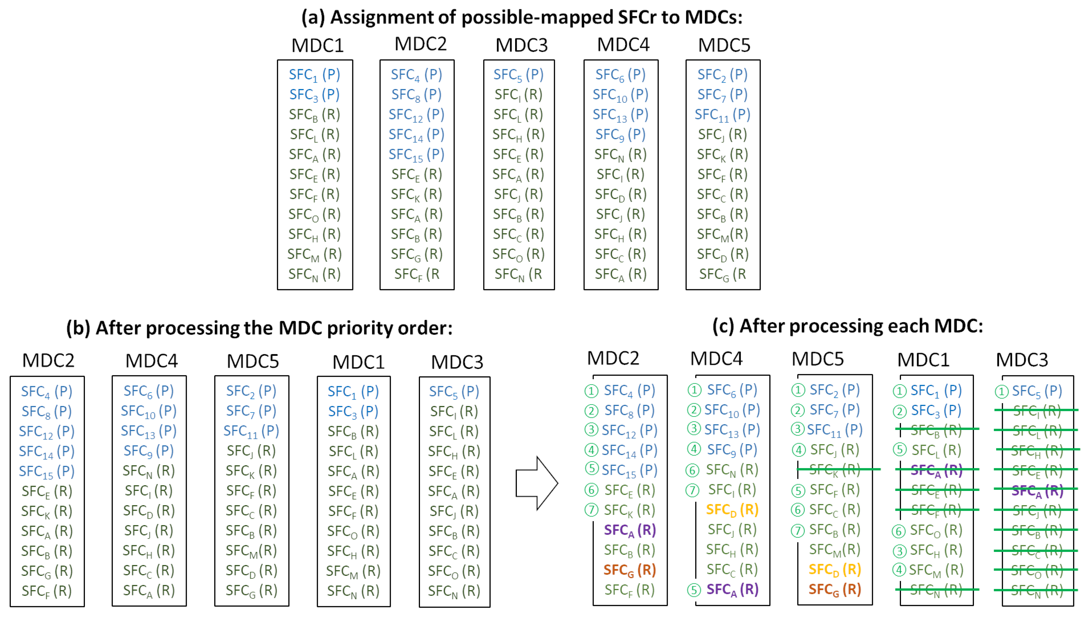
Before starting the mapping process, the total set of SFCrs is processed to identify the subset of MDCs to which each SFCrs could be mapped, taking into account the delay restrictions. Considering a particular SFCr, the substrate network, and its SAR, the SFCr is assigned as a potentially mapped SFCr to a particular MDC if the latency requirement is met. As a result of this procedure, an SFCr might be assigned to just one MDC (if only one MDC fulfills the latency requirement) or to more than one MDC. As can be seen in the example shown in Figure 2a, SFC is assigned as the potentially mapped SFCr to MDC1, MDC2, MDC3, and MDC4, while SFC is only attached to MDC1. Based on the number of candidate MDCs, the SFCrs are cataloged as Poor SFCrs (P-SFCrs) or Rich SFCrs (R-SFCrs): a poor SFCr only has a candidate MDC, while a rich SFCr has more than one candidate.
Once the set of potentially mapped SFCrs assigned to each MDC is obtained and the SFCrs have been classified as P-SFCrs or R-SFCrs, this information is used to establish the order of priority for MDCs to be processed. This processing priority value is obtained according to the number of P-SFCrs: the more P-SFCrs, the higher the processing order. Figure 2b shows the MDC process order, from left to right.
For each processed MDC, the potentially mapped P-SFCrs are mapped in the first place. Next, the R-SFCrs are mapped, using the minimum distance from the SAR to the MDC as the selection parameter. If more than one R-SFCr coincides on this parameter, the R-SFCr whose VNFrs have less difference from the existing VNFs in the MDC is chosen to be mapped firstly. The R-SFCrs that cannot be mapped on the current MDC due to the shortage of resources are left to be mapped on any subsequent MDC. However, it is also important to emphasize that, in this case, the R-SFCrs will be processed in a subsequent MDC with equal priority as the P-SFCrs in that MDC. According to this redefinition, the pending R-SFCrs of an already processed MDC will be mapped as soon as possible. However, this introduces a penalty to the R-SFCs of the currently processed MDC, as described below.
The priority-based SFCr mapping algorithm of the PG heuristic assumes that, although the memory and CPU capacities of the substrate nodes are limited, there will always be an available MDC that allows the fulfillment of the latency restrictions with enough resources to locate any SFCr of the total set. However, this assumption is rather unrealistic in real scenarios. There may be resources available on the network, but none of them meet the delay restrictions.
The non-fulfillment of this assumption, the priority order definition focused on MDCs, and the redefinition of the priority of pending R-SFCrs affect the probability of SFCr mapping failure. An SFCr is marked as poor if the number of possible MDCs is equal to one or rich if this number is higher than one, without considering the number of possible MDCs. Thus, an originally marked R-SFCr with a high number of possible MDCs may be mapped before an R-SFCr with a low number of possible MDCs (which has fewer options to be mapped), only because the priority of the MDC of the former R-SFCrs was higher due to the number of P-SFCrs.
Figure 2c illustrates the situation described above. Although the amount of SFCrs that can be mapped on an MDC depends on the MDC resources and the requested resources demanded by the VNFrs composing the SFCrs, by way of example, we consider that MDCs have the CPU and memory resources to accommodate seven SFCs at most. This assumption is used in order to simplify the scenario and to facilitate the problem identification and description. Firstly, MDC2 is processed: five P-SFCrs and two of the six R-SFCrs (SFC and SFC) are mapped on it. The rest of the R-SFCrs (SFC, SFC, SFC, and SFC) have to be mapped on other MDCs. Next, MDC4 is processed: After four P-SFCrs are mapped, the following mapped one is SFC. Although it is at the end of the possibly mapped list, it is treated with the same priority as the poor SFCrs (and consequently, with more priority than rich SFCrs of this MDC) because it is a pending SFCr of a previously processed MDC (in this case, MDC2). Finally, SFC and SFC are mapped on MDC2. Following the same procedure, the rest of the MDCs are processed. It can be seen that, at the end of the mapping process, SFC and SFC are not mapped on any MDC. In detail, SFC (a rich SFCr, but with only two possible MDCs) could have been mapped on MDC4, but SFC (a rich SFCr with four possible MDCs) was mapped instead because of the priority redefinition of pending requests. However, SFC could have been mapped on MDC1 or MD3, which have available resources, allowing the mapping of SFC.
Coming back to the PG heuristic, once the priority-based SFCr mapping algorithm finishes, a second stage called the VNFr merging algorithm is executed. In summary, starting from the mapping result of the first stage, the VNFr merging algorithm tries to move and merge VNFrs of the same type to reduce the number of VNF instances and consequently BRCs. During this second stage, the movement of VNFrs is done if the delay and resource restrictions of SFCrs are fulfilled, link and node resources are not violated, and the total cost is reduced.
6. Modified Priority-Based Greedy Heuristic
We propose an alternative to the PG heuristic that improves the VNF placement results, reducing the number of non-allocated SFCrs and maintaining similar total cost. Following the approach of the PG solution, the heuristic proposed in this work, which is called the Modified Priority-based Greedy heuristic (ModPG), consists of two stages: an SFCr mapping stage (described in Algorithm 1) and a VNFr merging stage (described in Algorithm 2).
| Algorithm 1: ModPG-SFCr mapping algorithm. |
 |
| Algorithm 2: ModPG-VNFr merging algorithm. |
 |
Although the problem statement defined in Section 4 considers Gas a variable number of CDCs, the ModPG heuristic (similarly to the PG heuristic in [13]) is defined considering a network scenario with just one CDC. A single CDC with limited resources would constrain the total set of SFCrs that could be mapped, but in both the PG and ModPG heuristics, this constraint has been considered outside the scope of this work, assuming CDC resources as infinite. A multiple CDC model will require extending the proposed heuristics by answering the problem of the load balancing among the links from MDCs to CDCs. This extension will be addressed in future works.
6.1. ModPG-SFCr Mapping Algorithm
The PG heuristic is based on the definition of a set of clusters to which the SFCrs will be assigned, and then, the features of each cluster determine the order in which the SFCrs are mapped to MDCs. In contrast to the PG, the mapping order of the SFCrs is determined by their own SFCrs and the set of possible MDCs that are associated with each one (Line 1 in Algorithm 1). In Procedure 1 (Algorithm 2), the SAR, the location of MDCs, the CDC in the substrate network, and the delay requirements of each SFCr are considered to check if the SFCr could be mapped on a particular MDC. For each SFCr, the propagation delay from its SAR to each MDC and the propagation delay from a certain MDC to the CDC are calculated using the shortest path algorithm (Lines 5–6 in Procedure 1). If the selection of a particular MDC fulfills the delay requirements, the MDC is considered a possible MDC to map the SFCr (Line 9 in Procedure 1).
| Procedure 1: SFCr classification procedure. |
 |
After obtaining the sets of possible MDCs associated with each SFCr, the SFCr mapping process begins. The SFCr with the minimum set of potential MDCs is selected (Line 3 in Algorithm 1). It is referred to as . is ordered from smallest to highest total propagation delay (Line 7 in Algorithm 1), and then, the first potential MDC with enough CPU and memory resources for mapping the SFCr is selected (Lines 9–14 in Algorithm 1). If necessary, new VNFs will be instantiated in the selected MDC () (Line 11 in Algorithm 1).
As described in Section 5, the PG mapping algorithm in [13] was defined assuming that there is always a potential MDC with enough available resources to host all the VNFrs of the SFCr that fulfills the delay requirements. The ModPG algorithm does not adopt this strong assumption. Therefore, if the SFCr being processed cannot be mapped on one of the potential MDCs entirely, the possibility of mapping the VNFrs on multiple MDCs is considered (Lines 15–18 in Algorithm 1). In this process, the resource availability of potential MDCs in is analyzed, and then, the MDC that maximizes the number of consecutive VNFrs of that can be mapped is selected. Next, taking into account the topology and delay restrictions imposed by the SFCr, additional MDCs that allow the mapping of the remaining VNFrs are located. In order to minimize the BRC cost, this process is executed in two stages. Firstly (Line 16 in Algorithm 1), only MDCs where required VNFs are already instantiated are considered. If the mapping process fails, then this restriction is removed (Line 18 in Algorithm 1), and VNFs are instantiated if required.
Once the set of SFCrs () is processed, the total cost of the resulting mapping solution () is obtained by applying Equation (1) (Line 19 in Algorithm 1).
6.2. ModPG-VNFr Merging Algorithm
Due to the fact that the mapping algorithm tries to minimize the delay and bandwidth cost by mapping, all the VNFrs of an SFCr are mapped on the same MDC whenever possible (Lines 8–14 in Algorithm 1) or on a reduced number of MDCs (Lines 15–18 in Algorithm 1). As a consequence, multiple instantiations of the same type of VNF are distributed in the network. That is, the volume of BRCs is not optimal. In addition, the result of the mapping algorithm does not optimize another relevant cost, the cost due to the activation of MDCs (the last term in Equation (1)). As pointed out in [13], as few MDCs as possible should be activated because the corresponding cost of activating MDCs is far higher than the other costs.
Taking into account both considerations, the ModPG-VNFr merging algorithm is defined as shown in Algorithm 2.
With the aim of reducing the cost of activating MDCs, the set of MDCs is sorted in increasing order considering the number of mapped VNFrs (Line 2 in Algorithm 2), and they are processed next (Line 3 in Algorithm 2). To reduce the complexity of the process, the implemented merging algorithm tries to empty the MDCs that host complete SFCrs (Line 7 in Algorithm 2). The moving of a sub-chain (a partial number of VNFrs belonging to an SFCr) involves not only the MDC to be emptied and the potential new destination MDCs, but also the MDCs that host the rest of the sub-chain.
If all the SFCrs mapped on the processed MDC can be potentially moved to other MDCs (or distributed to various MDCs) fulfilling all the resource, delay, and bandwidth requirements and constraints (Line 14 Algorithm 2), the new proposed mapping solution is considered as valid if the total cost is reduced (Lines 16–17 in Algorithm 2).
6.3. Complexity Analysis
In this part, the time complexity of the ModPG is analyzed. Firstly, for Algorithm 1, the time complexity of Procedure 1 is , in which is the time complexity of the Dijkstra algorithm. Then, for Lines 2–19 in Algorithm 1, all the SFCrs () are traversed in order to identify the SFCr with the smallest set of possible MDCs (). Next, this set is ordered, and in the worst case, three loops are traversed.
Thus, the total time complexity is . The first term comes from Procedure 1. The second term corresponds to the sorting process in Line 7. The last term derives from the minimum operator in Line 3 and the for-loops in Line 9, Line 16, and Line 18. Therefore, the complexity is at the level of O().
Regarding Algorithm 2, for Line 2, the time complexity is . Then, for Lines 3–17, all MDCs () are traversed. Generally speaking, (). Therefore, the total time complexity of ModPG is O().
7. Performance Evaluation
In this section, we evaluate the performance of the proposed ModPG heuristic and compare the results to the original approach. Both solutions were coded in Python. All experiments were performed on a computer with one Intel(R) Core(R) i5-7300U CPU 2.60GHz and 8GB of RAM.
7.1. Simulation Setup
The substrate network topology used to evaluate the proposed ModPG heuristic is the same topology used in [13]. There are 100 SARs, 50 MDCs, and 1 CDC. The topology containing the 100 SARs is generated by BRITE [22] based on a Waxman model [23], and then, the 50 MDCs are added to the topology based on a K-means algorithm [24]. The K-means clustering algorithm is used to obtain K clusters of SARs and then to place the K MDCs into their centers to minimize the within-cluster sum of squares. The propagation delay on each link obeys a uniform distribution of (0,2).
Similarly to the PG evaluation in [13], in order to obtain the total substrate resource cost Equation (1), all the weighted factors are equally balanced, that is , , , and are set to one. Different parameter settings for the proposed solution will be evaluated in a future work.
Replicating the setting used in [13], each SFCr is composed of four network functions that have to be hosted in MDCs. The virtualization of each network function in a node requires CPU and memory BRCs to be instantiated (as in the referenced work, both BRC values were set to 20 units), and a particular VNFr demands CPU and memory consumption (as in the referenced work, both requirements were randomly assigned following a uniform distribution of (40,80) units). The bandwidth consumption of each SFCr obeys a uniform distribution of (10,50).
Similarly, assuming the delay values considered in [13], a set of experiments was performed considering that the of each SFCr obeys a uniform distribution of (1,2) and that obeys a uniform distribution of (5,10). Analyzing the obtained results, from the point of view of SFCr classification as P-SFCrs or R-SFCrs, these delay distributions lead to a reduced amount of P-SFCrs. In particular, the number of P-SFCrs corresponds to around just 1% of the total number of SFCrs. Because the main objective of this performance evaluation is to verify the improvement of the proposed ModPG heuristic against the original PG heuristic when the percentage of P-SFCrs increases, two other sets of experiments were executed, where the percentage of P-SFCrs increased to around 15% and around 25%.
7.2. Results
Two scenarios were considered: the first scenario where the CPU and memory resources of each MDC were set to 3000 units; and the second scenario where the CPU and memory resources of each MDC were set to 4000 units. The second scenario replicates the simulation parameters defined in the baseline work [13]. To extend the evaluated scenarios, a more reduced capacity of MDCs was considered in the first scenario to study and compare the behavior of both proposals in a tightener situation.
For each scenario, different simulations were executed for different sets of SFCrs. Each experiment was executed 10 times.
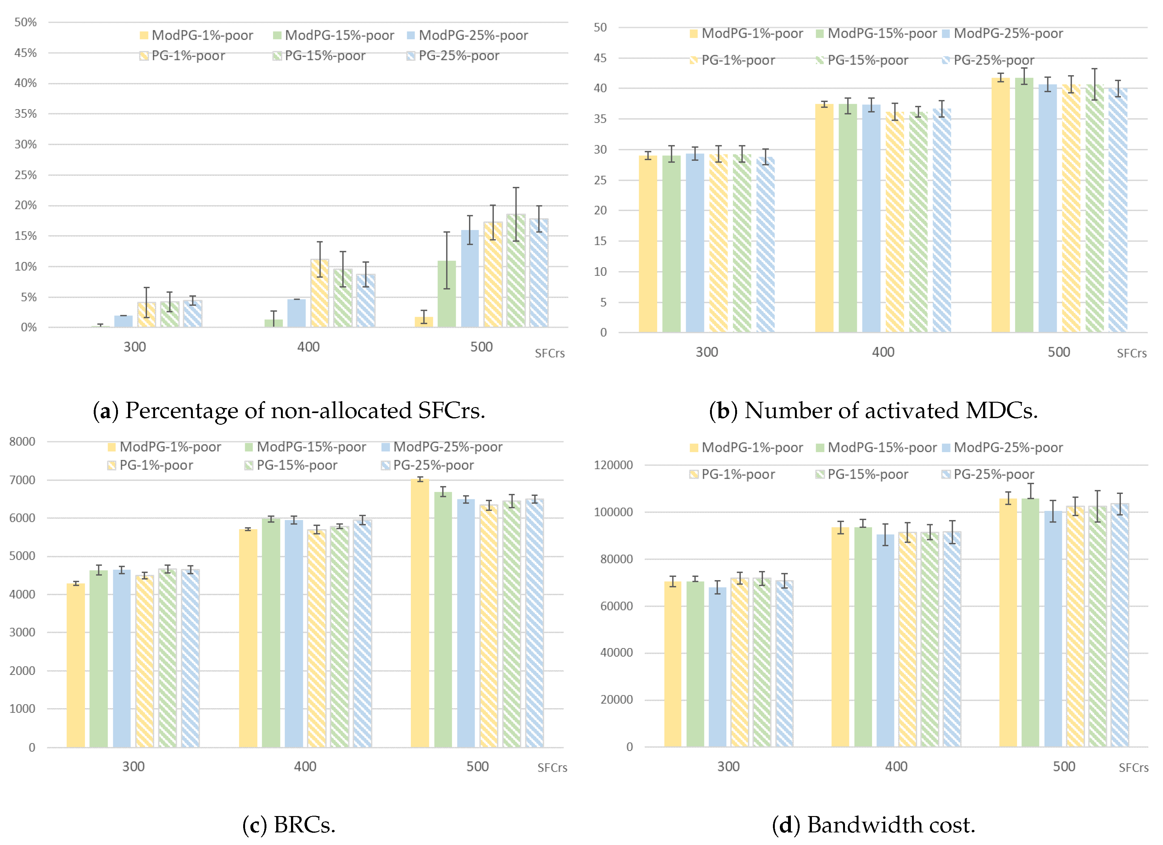
The percentage of non-allocated SFC requests, the total number of activated MDCs, the total BRC cost, and the bandwidth cost were the obtained values for each simulation. The last three parameters were used in [13] to evaluate the performance of the PG. In addition, the first parameter allows us to evaluate the suitability of the proposed ModPG solution when the number of SFCrs with strong low-delay requirements is significant.
Figure 3 and Figure 4 represent the evaluated parameters corresponding to the first and second scenario, respectively. The mean value is shown, and the 95% confidence interval is represented in the figures. Both figures compare the evaluated parameters using the proposed ModPG algorithm and the original PG algorithm. In both cases, the VNFr merging algorithm defined in Section 6.2 was implemented.
7.2.1. Performance Comparison Focused on Successful SFCr Allocation
The main objective of this work is to solve the weakness found in the referenced work as the percentage of SFC requests with strong low-delay restriction increases. As analyzed before in this work, this behavior affects the number of non-allocated SFCrs. Therefore, the first parameter to be evaluated is the percentage of non-allocated SFCrs, which is shown in Figure 3a and Figure 4a.
First of all, as expected, as the number of total SFCrs increases, the percentage of non-allocated SFCrs increases as well, because of the limited CPU and memory capacity of the MDCs. The maximum set of SFCrs in the first scenario was 500 and 600 in the second scenario.
On the other hand, taking into account the percentage of P-SFCrs shown in Figure 4a (and summarized in Table 2), the ModPG algorithm always results in a lower number of non-allocated SFCrs than the PG algorithm. Analyzing the obtained values in the case of 300 SFCrs, the percentage of non-allocated SFCrs using the ModPG algorithm is very low. That is, there are enough CPU and memory resources in the network to allocate almost all the SFCrs, even when the percentage of P-SFCr is 25%. However, the values obtained for the same set of experiments using the PG algorithm correspond to a higher number of non-allocated SFCrs (around 4% in the first scenario and 2% in the second scenario whatever the percentage of P-SFCrs). Although there are enough resources, the mapping order set by the PG algorithm penalizes SFCrs, which without being cataloged as P-SFCrs, have high latency restrictions. The same trend is observed considering 400 and 500 SFCrs.
As mentioned previously, in both scenarios and independent of the algorithm, as the number of SFCrs increases for the same amount of available CPU and memory resources, the inability to map SFCrs increases. This fact can be deduced from the result obtained by ModPG in the first scenario considering 500 SFCrs with 25% P-SFCrs and in the second scenario considering 600 SFCrs with 25% P-SFCrs. In these cases, the percentage of non-allocated SFCrs is almost equal using the ModPG solution and the PG solution, and this is because there are not enough resources to allocate such a high number of highly demanding SFCrs.
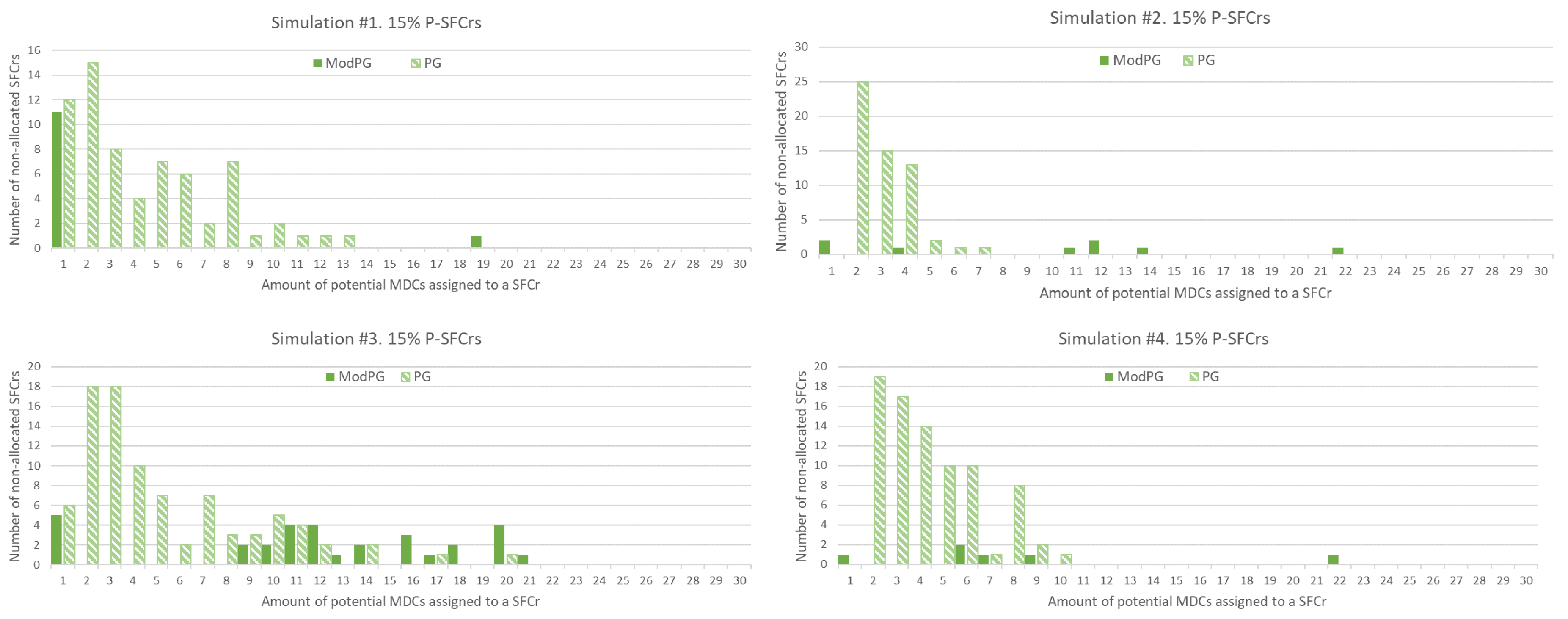
Figure 5 and Figure 6 corroborate the previous conclusions. The figures show the total amount of non-allocated SFCrs considering the size of the potential set of MDCs assigned by the SFCr classification procedure. It is important to remember that an SFCr is classified as a P-SFCr if the number of potential MDCs is only one. The results shown in Figure 5 correspond to four of the simulations considering 600 SFCrs with 15% P-SFCrs. It can be observed that the PG algorithm penalizes SFCrs with high latency restrictions, that is with a low number of potential MDCs, but that have not been cataloged as P-SFCrs because the value was not just one. The results obtained using the ModPG solution indicate that there are enough resources, but the mapping order set by the PG solution prevents their suitable allocation. The same behavior is observed in Figure 6. In this case, as observed before, the total number of non-allocated SFCrs is higher due to the shortage of resources. SFCrs with less strict delay requirements, and consequently with a higher number of potential MDCs, are not allocated.
7.2.2. Utilization of Network Resources
In this section, the total number of activated MDCs, the total BRC cost, and the bandwidth cost are analyzed.
Figure 3b and Figure 4b show the number of activated MDCs after successfully allocating the corresponding number of SFCrs. In the first scenario, both solutions offer similar results. The slight increment observed in the ModPG solution is due to the fact that, as evaluated in the previous section, the total number of allocated SFCrs is higher than when using the PG solution. Consequently, more MDC resources are needed. In the second scenario, where the total number of CPU and memory resources offered by MDCs is higher, the ModPG solution also presents positive results. In the case of 300 and 400 SFCrs to be mapped, the PG solution activates a lower number of MDCs. When the set size of the SFCrs increases, the ModPG solution activates a similar number of MDCs, but in a more efficient manner, because the proportion of non-allocated SFCrs is lower.
From Figure 3c and Figure 4c, it can be observed that the total cost due to BRC increases as the proportion of SFCrs with high latency restrictions grows. When the set of potential MDCs of the SFCrs is limited due to the latency restrictions, the VNFr merging algorithm is less efficient, which means an inability to reduce this cost. Again, the higher results obtained in the case of 500 SFCrs in the first scenario and 600 SFCrs in the second scenario is associated with the higher successful allocation rate.
8. Conclusions
This work proposes and evaluates a solution for the Virtual Network Function (VNF) placement problem in Micro Data Center (MDC)/Cloud Data Center (CDC) edge computing networks. This scenario defines a hierarchical and geo-distributed data center structure, where micro data centers are closer to service requesters than remote cloud data centers. This is a suitable scenario to solve the VNF placement problem when Service Function Chains (SFCs) present strict delay restrictions. In this paper, we propose a VNF placement solution that takes into account the latency and resource requirements imposed by the SFCs, the bandwidth and resource restrictions imposed by the network and the micro data centers, as well as the instantiation cost of VNFs. Due to the fact that the optimization objective, the minimization of the total substrate resource cost, is an NP-hard problem, a heuristic solution is proposed. The Modified Priority-based Greedy heuristic (ModPG heuristic) is coded and compared to a previously proposed solution (the PG heuristic) taking into account as an important factor the percentage of SFC requests with strong low-delay restrictions. Both solutions are compared considering the presence of 1%, 15%, and 25% of SFCrs with strong low-delay restrictions. For the performance evaluation, the following parameters are considered: the percentage of non-allocated SFCrs, the number of activated MDCs, the BRC, and the bandwidth cost. The results show that the ModPG heuristic obtains the objective, the optimization of the target cost, similar to the original proposal, and at the same time, it obtains the reduction of non-allocated SFC requests.
As future work, we plan to evaluate the proposal performance considering different weighing parameter values (, , , and ) defining the total substrate resource cost. In addition, it will be interesting to evaluate the results offered by the ModPG heuristic in a wider set of network topologies, establishing specific NFV resource requirements and MDC and CPC capacities expressed in terms of the number of cores and memory units.
Author Contributions
Conceptualization, P.M.-L., J.P.M.-G., and J.M.-S.; methodology, P.M.-L., J.P.M.-G., and J.M.-S.; software, P.M.-L.; validation, P.M.-L., J.P.M.-G., and J.M.-S.; formal analysis, P.M.-L., J.P.M.-G., and J.M.-S.; investigation, P.M.-L.; resources, P.M.-L.; data curation, P.M.-L.; writing, original draft preparation, P.M.-L., J.P.M.-G., and J.M.-S.; writing, review and editing, P.M.-L.; visualization, P.M.-L.; supervision, P.M.-L.; project administration, P.M.-L.; funding acquisition, J.M.-S. All authors read and agreed to the published version of the manuscript.
Funding
This work was supported by the AEI/FEDER, UE Project Grants TEC-2016-76465-C2-1-R (AIM).
Conflicts of Interest
The authors declare no conflict of interest.
Abbreviations
The following abbreviations are used in this manuscript:
| AR | Augmented Reality |
| BRC | Basic Resource Consumption |
| CAPEX | CAPital EXpenditure |
| CDC | Cloud Data Center |
| COTS | Commercial-Off-The-Shelf |
| EC | Edge Computing |
| ILP | Integer Linear Programming |
| IoT | Internet of Things |
| MDC | Micro Data Center |
| ModPG | Modified Priority-based Greedy |
| NF | Network Function |
| NFV | Network Function Virtualization |
| OPEX | OPerational EXpenditure |
| PG | Priority-based Greedy |
| P-SFCr | Poor Service Function Chain request |
| R-SFCr | Rich Service Function Chain request |
| SaaS | Software-as-a-Service |
| SAR | Service Access Router |
| SFC | Service Function Chain |
| SFCr | Service Function Chain request |
| VM | Virtual Machine |
| VNF | Virtual Network Function |
| VNFr | Virtual Network Function request |
| VR | Virtual Reality |
Appendix A
The VNF placement problem can be formulated as an Integer Linear Programming (ILP) model as follows.
Appendix A.1. Constraints
A first VNF placement constraint can be formulated as follows:
that is, a VNFr and SAR in an SFCr must be mapped on only one node in the substrate network. The binary indicates whether the VNFr in SFCr is mapped on substrate node .
Due to geographical considerations, each SFCr specifies its SAR. Therefore:
In addition, VNFrs in and can only be mapped on MDCs and CDCs, respectively. Therefore:
The CPU and memory consumptions of the VNFrs on an MDC cannot exceed the CPU and memory capacities of the MDC:
In Equations (A4) and (A5), the first term indicates the total CPU and memory consumption by the VNFs mapped on the substrate node . The second term indicates the total CPU BRCs and memory BRCs, respectively, due to the instantiation of VNFs.
Regarding BRCs, the variable indicates if one or more than one VNFrs of type VNF are mapped on , and it is defined as:
where . , which indicates if VNFr in SFCr demands VNF ; it is not a variable because the type of VNFr in an SFCr is known.
In addition, if there is more than one VNFr mapped on one MDC, the MDC has to be activated. This constraint can be formulated as:
It is assumed that CDCs are always in operation.
The model does not consider resource consumption on SARs, and it also assumes resource-rich CDCs.
As described in Section 4.2, indicates the logical links between VNFrs of SFCr . These logical links are represented by , where and are two consecutive VNFrs of SFCr . To model the bandwidth constraints, a link variable is defined:
Due to the VN reuse strategy, two different VNFrs in one SFCr can be mapped on the same substrate node. Therefore, the flow of the logical link may go through a substrate link or not. This fact determines the following constraint:
Using this variable, the bandwidth constraint can be modeled as follows. For each link in the substrate network, the link capacity must be satisfied:
where indicates the bandwidth consumption of the logical link in SFCr .
In this scenario, the edge computing network allows the location of sensitive services in MDCs and not in remote CDCs. Therefore, considering only propagation delays, the ILP model includes two latency constraints: , SAR to MDC tolerated propagation delay; and , the entire tolerated propagation delay:
Finally, the following flow conservation constraints must be satisfied:
Equation (A13) indicates whether a logical link is mapped on one of the substrate links that leave out node , and Equation (A14) indicates whether the logical link is mapped on one of the substrate links that go in node . Both equations ensure that one logical link can only be mapped on a single path. Equation (A15) ensures that the path in the substrate network is consistent for a logical link.
Appendix A.2. Optimization Target
The optimization target of the VNF placement problem is to minimize the total cost:
where the total CPU resource consumption is:
The total memory resource consumption is:
The total CPU BRC is:
The total memory BRC is:
The total bandwidth consumption is:
The total cost of activating the MDC is:
As pointed out in Section 4.3, the mapping process should try to activate as few MDCs as possible, due to the additional cost involved. To introduce this strategy to the optimization model, a value that represents the activation of an MDC is defined, which is assigned a greater value than other costs.
References
- Varghese, B.; Buyya, R. Next generation cloud computing: New trends and research directions. Future Gener. Comput. Syst. 2018, 79, 849–861. [Google Scholar] [CrossRef] [Green Version]
- Shi, W.; Cao, J.; Zhang, Q.; Li, Y.; Xu, L. Edge Computing: Vision and Challenges. IEEE Internet Things J. 2016, 3, 637–646. [Google Scholar] [CrossRef]
- Satyanarayanan, M. The emergence of edge computing. Computer 2019, 50, 30–39. [Google Scholar] [CrossRef]
- Elazhary, H. Internet of Things (IoT), mobile cloud, cloudlet, mobile IoT, IoT cloud, fog, mobile edge, and edge emerging computing paradigms: Disambiguation and research directions. J. Netw. Comput. Appl. 2019, 128, 105–140. [Google Scholar] [CrossRef]
- Mijumbi, R.; Serrat, J.; Gorricho, J.L.; Bouten, N.; Turck, F.D.; Boutaba, R. Network Function Virtualization: State-of-the-Art and Research Challenges. IEEE Commun. Surv. Tutor. 2015, 18, 236–262. [Google Scholar] [CrossRef] [Green Version]
- Han, B.; Gopalakrishnan, V.; Ji, L.; Lee, S. Network function virtualization: Challenges and opportunities for innovations. IEEE Commun. Mag. 2015, 53, 90–97. [Google Scholar] [CrossRef]
- Yia, B.; Wang, X.; Lic, K.; Das, S.K.; Huang, M. A comprehensive survey of Network Function Virtualization. Comput. Netw. 2018, 212–262. [Google Scholar] [CrossRef]
- Zhang, C.; Joshi, H.P.; Riley, G.F.; Wright, S.A. Towards a virtual network function research agenda: A systematic literature review of VNF design considerations. J. Netw. Comput. Appl. 2019, 146, 102417. [Google Scholar] [CrossRef]
- He, M.; Alba, A.M.; Basta, A.; Blenk, A.; Kellerer, W. Flexibility in softwarized networks: Classifications and research challenges. IEEE Commun. Surv. Tutor. 2019, 21, 2600–2636. [Google Scholar] [CrossRef]
- Sun, G.; Zhu, G.; Liao, D.; Yu, H.; Du, X.; Guizani, M. Cost-Efficient Service Function Chain Orchestration for Low-Latency Applications in NFV Networks. IEEE Syst. J. 2018, 13, 3877–3888. [Google Scholar] [CrossRef]
- Bellavista, P.; Callegati, F.; Cerroni, W.; Contoli, C.; Corradi, A.; Foschini, L.; Pernafini, A.; Santandrea, G. Virtual network function embedding in real cloud environments. Comput. Netw. 2015, 3, 506–517. [Google Scholar] [CrossRef]
- Rafique, W.; Qi, L.; Yaqoob, I.; Imran, M.; Rasool, R.U.; Dou, W. Complementing IoT Servthe hrough Software Defined Networking and Edge Computing: A Comprehensive Survey. IEEE Commun. Surv. Tutor. 2020, 22, 1761–1804. [Google Scholar] [CrossRef]
- Li, D.; Hong, P.; Xue, K.; Pei, J. Virtual network function placement and resource optimization in NFV and edge computing enabled networks. Comput. Netw. 2019, 152, 12–24. [Google Scholar] [CrossRef]
- Cao, J.; Zhang, Y.; An, W.; Chen, X.; Sun, J.; Han, Y. VNF-FG design and VNF placement for 5G mobile networks. Sci. China Inf. Sci. 2017, 60, 040302. [Google Scholar] [CrossRef]
- Xu, Q.; Gao, D.; Li, T.; Zhang, H. Low Latency Security Function Chain Embedding Across Multiple Domains. IEEE Access 2018, 6, 14474–14484. [Google Scholar] [CrossRef]
- Fotoglou, I.; Papathanail, G.; Pentelas, A.; Papadimitriou, S. Towards Cross-Slice Communication for Enhanced Service Delivery at the Network Edge. In Proceedings of the 6th IEEE Conference on Network Softwarization (NetSoft), Virtual Conference, Ghent, Belgium, 29 June–3 July 2020. [Google Scholar]
- Rosa, R.V.; Rothenberg, C.E. The Pandora of Network Slicing: A Multi-Criteria Analysis. Trans. Emerg. Telecommun. Technol. 2020, 31, e3651. [Google Scholar] [CrossRef]
- Zhang, Q.; Liu, F.; Zeng, C. Adaptive Interference-Aware VNF Placement for Service-Customized 5G Network Slices. In Proceedings of the IEEE INFOCOM 2019-IEEE Conference on Computer Communications, Paris, France, 29 April–2 May 2019. [Google Scholar]
- Zhao, D.; Ren, J.; Lin, R.; Xu, S.; Chang, V. On Orchestrating Service Function Chains in 5G Mobile Network. IEEE Access 2019, 9, 39402–39416. [Google Scholar] [CrossRef]
- Yang, S.; Li, F.; Trajanovski, S.; Yahyapour, R.; Fu, X. Recent Advances of Resource Allocation in Network Function Virtualization. IEEE Trans. Parallel Distrib. Syst. 2021, 32, 295–314. [Google Scholar] [CrossRef]
- Gurobi Optimizer. Available online: https://www.gurobi.com/products/gurobi-optimizer (accessed on 26 August 2020).
- Medina, A.; Lakhina, A.; Matta, I.; Byers, J. BRITE: An Approach to Universal Topology Generation. In Proceedings of the International Workshop on Modeling, Analysis and Simulation of Computer and Telecommunication Systems, Atlanta, GA, USA, 27–29 September 2005. [Google Scholar]
- Waxman, B. Routing of Multipoint Connections. IEEE J. Sel. Areas Commun. 1988, 6, 1617–1622. [Google Scholar] [CrossRef]
- Likas, A.; Vlassis, N.; Verbeek, J.J. The Global k-means clustering algorithm. Patter Recognit. 2003, 36, 451–461. [Google Scholar] [CrossRef] [Green Version]
Figure 1.
Problem outline using the example described in [13].
Figure 1.
Problem outline using the example described in [13].

Figure 2.
Example of priority-based mapping algorithm execution. Five MDCs and a set of 30 SFCrs are considered. It is assumed that the MDCs have CPU and memory resources to accommodate seven SFCs at most. (a) shows the assignment of possibly mapped SFCrs to each MDC taking into account the delay restrictions. The SFCrs that are only assigned to one possible MDC (P-SFCrs) are shown in blue and the R-SFCrs in green. (b) shows the MDC processing priority order (from left to right). Finally, (c) shows the result of the mapping algorithm. The SFCrs with a number on the left are mapped ones. The SFCrs without a number and that are not crossed out are pending SFCrs that will be considered in subsequent MDCs, and crossed out SFCrs indicate SFCrs that have been already mapped in previous MDCs.

Figure 3.
Scenario 1: CPU and memory capacity of MDCs set to 3000.

Figure 4.
Scenario 2: CPU and memory capacity of MDCs set to 4000.

Figure 5.
Detailed analysis of non-allocated SFCrs. Sets of 600 SFCrs with 15% P-SFCrs. Scenario 2: CPU and memory capacity of MDCs set to 4000.
Figure 5.
Detailed analysis of non-allocated SFCrs. Sets of 600 SFCrs with 15% P-SFCrs. Scenario 2: CPU and memory capacity of MDCs set to 4000.

Figure 6.
Detailed analysis of non-allocated SFCrs. Sets of 600 SFCrs with 25% P-SFCrs. Scenario 2: CPU and memory capacity of MDCs set to 4000.
Figure 6.
Detailed analysis of non-allocated SFCrs. Sets of 600 SFCrs with 25% P-SFCrs. Scenario 2: CPU and memory capacity of MDCs set to 4000.


Table 1.
Notations.
| 4-tuple substrate network | |
| A substrate node in the substrate network | |
| The substrate link between the substrate nodes and | |
| The propagation delay of substrate link | |
| The link capacity of substrate link | |
| The CPU and memory resources of substrate node | |
| The SFCr set | |
| 6-tuple description: indicates the SAR of SFCr; indicates the part of the SFCr that should be placed in MDCs; indicates the part of the SFCr that should be in CDC; indicates the logical links (that is, the order) between the VNFrs; is a latency constraint that limits the tolerated propagation latency from SAR to MDC; and is the latency constraint that limits the tolerated propagation latency from SAR to CDC | |
| A VNFr involved in an SFCr that demands CPU and memory resources | |
| The logical link between and , two consecutive VNFrs in an SFCr | |
| The CPU and memory consumption of VNFr in SFCr | |
| , | The CPU and memory BRCs when instantiating a new VNF |
| on one MDC or CDC |
Table 2.
Percentage of non-allocated SFCrs: mean values.
| Scenario 1 | Scenario 2 | ||||||
|---|---|---|---|---|---|---|---|
| 1% | 15% | 25% | 1% | 15% | 25% | ||
| 300 SFCrs | ModPG | 0% | 0.23% | 1.97% | 0% | 0.17% | 0.87% |
| PG | 4.10% | 4.20% | 4.43% | 1.73% | 1.97% | 2.30% | |
| 400 SFCrs | ModPG | 0% | 1.38% | 4.68% | 0% | 0.20% | 1.40% |
| PG | 11.18% | 9.58% | 8.70% | 4.93% | 5.30% | 3.20% | |
| 500 SFCrs | ModPG | 1.78% | 10.98% | 15.96% | 0.04% | 1.06% | 4.88% |
| PG | 17.22% | 18.58% | 17.82% | 6.64% | 10.38% | 7.62% | |
| 600 SFCrs | ModPG | – | – | – | 0.27% | 2.65% | 13.37% |
| PG | – | – | – | 14.7% | 11.55% | 14.27% | |
© 2020 by the authors. Licensee MDPI, Basel, Switzerland. This article is an open access article distributed under the terms and conditions of the Creative Commons Attribution (CC BY) license (http://creativecommons.org/licenses/by/4.0/).
Share and Cite
MDPI and ACS Style
Manzanares-Lopez, P.; Muñoz-Gea, J.P.; Malgosa-Sanahuja, J. VNF Placement for Service Function Chains with Strong Low-Delay Restrictions in Edge Computing Networks. Appl. Sci. 2020, 10, 6573. https://doi.org/10.3390/app10186573
AMA Style
Manzanares-Lopez P, Muñoz-Gea JP, Malgosa-Sanahuja J. VNF Placement for Service Function Chains with Strong Low-Delay Restrictions in Edge Computing Networks. Applied Sciences. 2020; 10(18):6573. https://doi.org/10.3390/app10186573
Chicago/Turabian StyleManzanares-Lopez, Pilar, Juan Pedro Muñoz-Gea, and Josemaria Malgosa-Sanahuja. 2020. "VNF Placement for Service Function Chains with Strong Low-Delay Restrictions in Edge Computing Networks" Applied Sciences 10, no. 18: 6573. https://doi.org/10.3390/app10186573
Note that from the first issue of 2016, this journal uses article numbers instead of page numbers. See further details here.