Article

Optimal Harmonic Mitigation in Distribution Systems with Inverter Based Distributed Generation

1
Electrical Engineering Department, Mechanical and Electrical Research Institute, NWRC, Cairo 13621, Egypt
2
Electrical Engineering Department, Faculty of Engineering, Kafrelsheikh University, Kafrelsheikh 33516, Egypt
3
Electrical Engineering Department, Faculty of Engineering, Menoufiya University, Shebin El-Kom 32511, Egypt
4
Department of Electrical Engineering and Automation, Aalto University, FI-00076 Espoo, Finland
5
Electrical Engineering Department, Faculty of Engineering, Aswan University, Aswan 81542, Egypt
6
Electrical Engineering Department, Shoubra Faculty of Engineering, Benha University, Cairo 11629, Egypt
*
Author to whom correspondence should be addressed.
Appl. Sci. 2021, 11(2), 774; https://doi.org/10.3390/app11020774
Submission received: 23 December 2020 / Revised: 11 January 2021 / Accepted: 12 January 2021 / Published: 15 January 2021
(This article belongs to the Special Issue Power Quality in Electrical Power Systems)

Abstract

:
In recent years, with the widespread use of non-linear loads power electronic devices associated with the penetration of various renewable energy sources, the distribution system is highly affected by harmonic distortion caused by these sources. Moreover, the inverter-based distributed generation units (DGs) (e.g., photovoltaic (PV) and wind turbine) that are integrated into the distribution systems, are considered as significant harmonic sources of severe harmful effects on the system power quality. To solve these issues, this paper proposes a harmonic mitigation method for improving the power quality problems in distribution systems. Specifically, the proposed optimal planning of the single tuned harmonic filters (STFs) in the presence of inverter-based DGs is developed by the recent Water Cycle Algorithm (WCA). The objectives of this planning problem aim to minimize the total harmonic distortion (THD), power loss, filter investment cost, and improvement of voltage profile considering different constraints to meet the IEEE 519 standard. Further, the impact of the inverter-based DGs on the system harmonics is studied. Two cases are considered to find the effect of the DGs harmonic spectrum on the system distortion and filter planning. The proposed method is tested on the IEEE 69-bus distribution system. The effectiveness of the proposed planning model is demonstrated where significant reductions in the harmonic distortion are accomplished.

1. Introduction

Nowadays, distribution system power quality is one of the most important challenges, especially after the widespread use of harmonic sources in distribution systems which is considered as one of the most effective factors on power quality [1]. Harmonics presence in the distribution system can result in excessive losses, system equipment’s overheating, and damage [2]. Consequently, to keep the distribution system reliable and working at a high performance, harmonics levels should be kept within the allowable limits approved in the international standards [3]. However, due to the widespread of power electronics devices and nonlinear loads in the distribution system, harmonics levels in the distribution system may exceed the standard limits. Therefore, harmonic mitigation becomes more interesting in distribution systems to decrease distortion levels and enhance system performance [4].
On the other hand, huge efforts have been exerted for increasing the penetration of distributed generation units (DGs) in the distribution systems especially the renewable DGs which are inverter-based such as PV and wind generation sources [5]. The presence of DGs in distribution systems provides many technical, environmental, and economic merits [6,7,8,9], but on the other hand, the harmonic content of the inverter-based DGs may increase the harmonic distortion problem in the distribution system [10,11]. To effectively analyze the harmonic distortion in the distribution systems, load-flow and harmonic load flow studies are of prime importance. Therefore, various load flow and harmonic load flow methods are presented for analyzing different topologies of radial distribution systems as in [12,13,14,15].
Further, to solve the harmonic distortion problem, several methods had been proposed [16,17]. In [18], 12-Pulse Rectifiers were used to reduce the amount of generated harmonics, but this technique requires special cooling systems. However, the active filter can be considered as an effective method for harmonic damping in distribution systems [19], it is considered an uneconomic method due to its high cost. Single tuned passive harmonic filters still one of the most common methods for harmonic mitigation due to their effectiveness and economic benefits. The single tuned passive filters are designed to trap the harmonic in the filter-branch depending on the low impedance of the filter-branch at the tuned harmonic order [20]. Various methods were developed for the optimal design of passive harmonic filter based on optimization techniques such as particle swarm optimization [20], simulated annealing [21], and fuzzy linear programming [22].
Such optimization techniques are considered for solving this nonlinear problem which has a very large search space. Therefore, these techniques are considered as a fast, robust, and accurate method to solve this type of problem. Selecting the optimal placement of the harmonic filters in the system has an essential effect on the system harmonic mitigation. Authors in [23] presented a method for single-tuned filter placement in a small distribution system based on a genetic algorithm to reduce the harmonic distortion. In [24], the authors presented a method for determining the optimal allocation of passive filters in an industrial distribution network based on the harmonic similarity metric. In [25], the authors presented two sensitivity indices as a guide for the passive filter placement problem which can determine the sensitive buses for filter placement. In [26], a multi-objective optimization problem was considered for solving the optimal planning problem of passive filter considering specific harmonic orders without considering the harmonic distortion resulted from DG units. In [27], simultaneously planning of both inverter-based DGs and passive filters in the distorted distribution system are considered for minimizing THD and power loss. In [28], the optimal placement and sizing of capacitor banks and inverter-based DGs was employed by biogeography-based optimization (BBO) algorithm considering the harmonic content of the DGs at different load levels. In [29], the authors presented an economic study that approved the economic benefits of using passive filters especially in the case of the nonlinear loads that exceed 1 MVA. In [30], the design of single tuned filters was carried out by using ETAP software in distribution systems with PV systems to eliminate the harmonics and their impact on the system. A comprehensive analysis of the single tuned filter parameters selection and its effect on the harmonic mitigation is presented in [16].
As illustrated in the abovementioned literature review, non-linear loads and renewable energy sources can increase the harmonic distortion in distribution systems, which leads to harmful effects on the system power quality. In this paper, a proposed method is introduced for simultaneously determine the optimal design, number, and placement of single tuned harmonic filters by using the Water Cycle Algorithm (WCA) which is implemented as a multi-objective optimization algorithm. The harmonic spectrums of the inverter-based DGs implement in the distribution system are considered beside the harmonic emissions from the nonlinear loads. This study is considered a multidimensional study as it achieves both technical and economic merits throughout the objectives that include minimizing: the total harmonic distortion, cost of power loss and that of the filter investment cost, and improvement of the voltage profile. Harmonic load flow with and without a filter is implemented for analyzing the systems’ harmonics. The effect of harmonic spectrums of the DGs on the harmonic distortion in the system is studied through two cases studied.
The organization of the current paper is ordered as follow: Section 2 presents the problem formulation, Section 3 presents the optimization algorithm and electric scheme representation, Section 4 presents, the proposed filters planning procedure, Section 5 presents the application of the proposed method, Section 6 presents simulation results and discussion, and Section 7 presents the conclusions.

2. Problem Formulation

This study aims to determine the optimal design, number, and placement of single tuned harmonic filters in distorted distribution systems. The harmonic spectrum of the DG units in the system is considered. The proposed method aims to minimize THD, power loss, and filter investment cost, and improve the system voltage through the following objective functions.

2.1. Objective Functions

Three objective functions are considered in this optimization problem as follows:

2.1.1. Minimizing the Total Harmonic Distortion (f1)

THD of the system should be kept as low as possible according to the following equation [27].
f 1 = min i = 1 N ( 1 V 1 i h = 2 H V h i 2 )
where V1i is the fundamental bus voltage, Vhi is the harmonic order (h) voltage at bus i, and N is the total number of buses.

2.1.2. Improving the Voltage Profile (f2)

This objective function can be described as [22]:
f 2 = min i = 1 N ( V i V i s p e c V i max V i min ) 2
where Vi is the voltage of bus i, V i s p e c is the Specified voltage magnitude (1.0 p.u), V i m a x and V i m i n are the maximum and minimum fundamental voltage at bus i.

2.1.3. Minimizing the Cost of the Total Active Power Loss and That of the Filter Investment Cost (f3)

f 3 = min [ k p × P l o s s + C f i l t e r ]
where kp is the annual cost per unit of the real power loss ($/kW/year); Cfilter is the filter investment cost; Ploss is the active power loss which can be described as [31]:
P l o s s = i = 1 n b P l o s s i 1 F u n d a m e n t a l + i = 1 n b h = 3 h max P l o s s i h H a r m o n i c
where nb is the number of branches and hmax is the highest harmonic order of interest.
Cfilter can be calculated as follows [25]:
C f i l t e r = i = 1 n f ( k C × Q C i + k L × Q L i + k R × P R i )
in which nf is the total number of filters, kc, kL, and kR are the cost coefficients of the filter capacitor, inductor, and resistor, respectively, which are equals and equal to 3 $/kVAR [32].
This optimization problem is considered as a multi-objective optimization, which can be implemented using the weighting factors approach. So, the normalized fitness function (FF) can be formulated as:
F F = min ( k 1 f 1 f 1 max + k 2 f 2 f 2 max + k 3 f 3 f 3 max )
where, k1, k2, and k3 are the weighting factors.

2.2. Constraints

This optimization problem constitutes the following constraints:
(1)
Voltage limits:
V min V i   V max     ,
where,
| V i | = | V i ( 1 ) | 2 + h = 3 h max | V i ( h ) | 2
(2)
Power balance constraints:
i = 1 N G P G i P L = P d i = 1 N G Q G i Q L = Q d
PL and QL are active and reactive power losses, respectively. Pd and Qd are load demand active and reactive powers. PGi and QGi are active and reactive power at ith DG unit, respectively.
(3)
Generation operating limits:
P G i min P G i P G i max , Q G i min Q G i Q G i max
(4)
Harmonic distortion limits:
T H D i ( x ) T H D max
I H D i , h ( x ) I H D max
where THDmax and IHDmax are the maximum allowable total harmonic distortion and individual harmonic distortion at each bus, which have values equal to (5% and 3%), respectively, according to the IEEE-519’s standard [3]. Note that the THD as low as possible can be considered as a preventive action to protect the system from any future increase in harmonic sources. If we design the filters to only meet the standard, it needs to redesign the filters with each increase in the harmonic emissions. Added to that, we considered two conflicting objectives (Minimizing the THD and the filter investment cost) to guarantee the optimal economic solution.

3. Optimization Algorithm and Electric Scheme Representation

3.1. Water Cycle Optimization Algorithm

WCA is considered as one of the recent optimization techniques which are used with single and multi-objective optimization problems. In [33], a comparative study has been presented and approved the effectiveness of the WCA over other well-known algorithms in terms of computational effort and accuracy for multi-objective optimization problems. WCA was also applied to optimal planning of DGs and capacitors [8] where its performance was compared with other well-known algorithms and it achieved a better performance in terms of accuracy and convergence speed.
Similar to other metaheuristic algorithms, the WCA algorithm starts with random initialization of a set of solutions. Each solution represents a raindrop. In each iteration for finding better solutions, the best raindrop is selected to be the sea “solution that has the best objective value”, the number of good raindrops is chosen to be the rivers and the remainder raindrops are assumed to be streams which flow to the sea or the rivers. the control variables (X) are modified to be close to the sea or the rivers as the following equations [33]:
X s t r e a m i + 1 =   X s t r e a m i   + r a n d × U × ( X r i v e r i X s t r e a m i )
X r i v e r i + 1 = X r i v e r i + r a n d × U × ( X s e a i X r i v e r i )
where rand is a random number between 0 and 1, and U is a constant. If the distance between a river and sea is very small, new random solutions are inserted into the set of the solution to avoid getting trapped in the local optimal which is called the evaporation process.

3.2. Electric Scheme and Single Tuned Filter Representation

Considering a simple radial distribution system consists of six buses and has two nonlinear loads in buses 3 and 5 as shown in Figure 1. The nonlinear loads inject harmonic currents into the system. For each harmonic order, backward/forward load flow calculation is done with the same sequence of fundamental load flow, with considering the Substation voltage to be zero, all loads are considered to be constant impedance load, its impedance is calculated at the specified harmonic frequency. The imaginary part of the line section impedances between buses will be multiplied with the harmonic order, and every nonlinear load is represented by a constant impedance load in parallel with a current source. This current source injects current equals to the load current at normal frequency multiplied with harmonic ratio of this harmonic order as shown in Figure 2. Where r and x are the resistance and reactance of the line, rL and xL are the resistance and reactance of the loads, VS is the source voltage.
The resonance that may occur after installing the filter may represent a problem while doing harmonic load flow due to the very low impedance (short circuit) of the filter-branch, especially at the tuned harmonic order. If the filter impedance is high, the filter will be modelled as a constant impedance load as shown in Figure 2. While, if the filter is in resonance case, it will be modelled as a constant current source with negative polarity (absorb constant current) as shown in Figure 3. The value of this current is calculated from the Thevenin equivalent circuit shown in Figure 4 as follow:
i f i l t e r = v t h z t h
where vth is Thevenin voltage and Zth is Thevenin equivalent impedance. The Thevenin equivalent phase impedance will be the sum of the phase impedance of each device between the system voltage source node and the point of the short circuit [34].
The pass_band practical criteria presented in [16] is applied in determining if the filter in resonance mode or high impedance not. This pass_band practical criterion studied the effect of the single tuned filter parameters such as filter size (QC), quality factor (Qf), and tuned frequency (tf) on the filter performance. The analysis showed that the Qf has a less significant effect than the QC and tf on the impedance–frequency characteristics curve. Increasing tf or QC makes the curve be flatter as shown in Figure 5. So the pass_band is defined as the band which contains the frequencies at which the filter impedance is very low compared with the system minimum impedance load “if the filter impedance is lower than 1/10 of the system minimum impedance load” [16]. This declares the concept shown in Figure 5 that the filter passband increases with increasing the filter capacitive reactive power and increasing the order of tuned frequency. For example, the 7th order harmonic filter has more flatten impedance characteristics curve rather than that of the 5th order filter, as shown in Figure 5a.

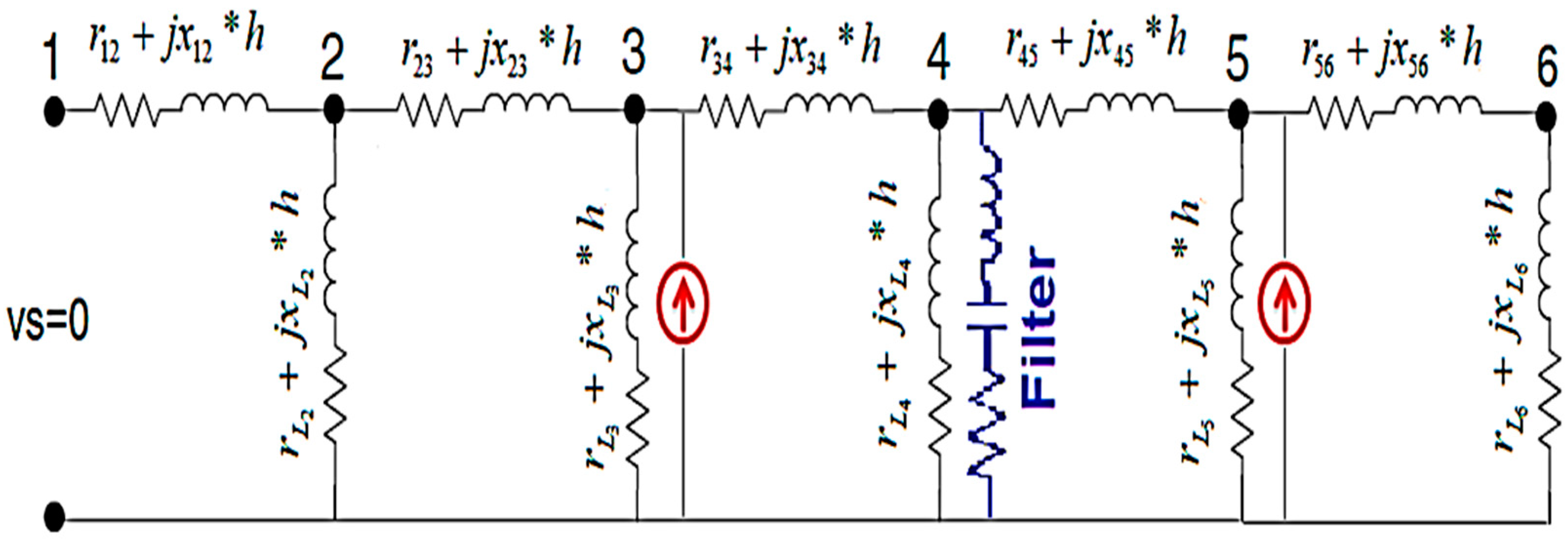
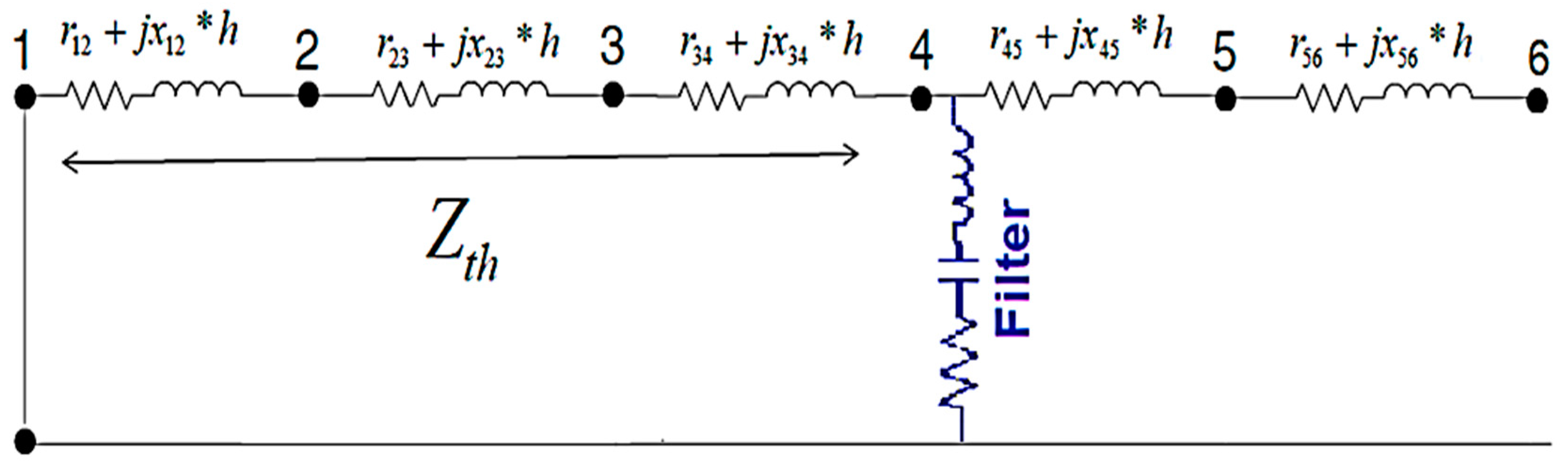
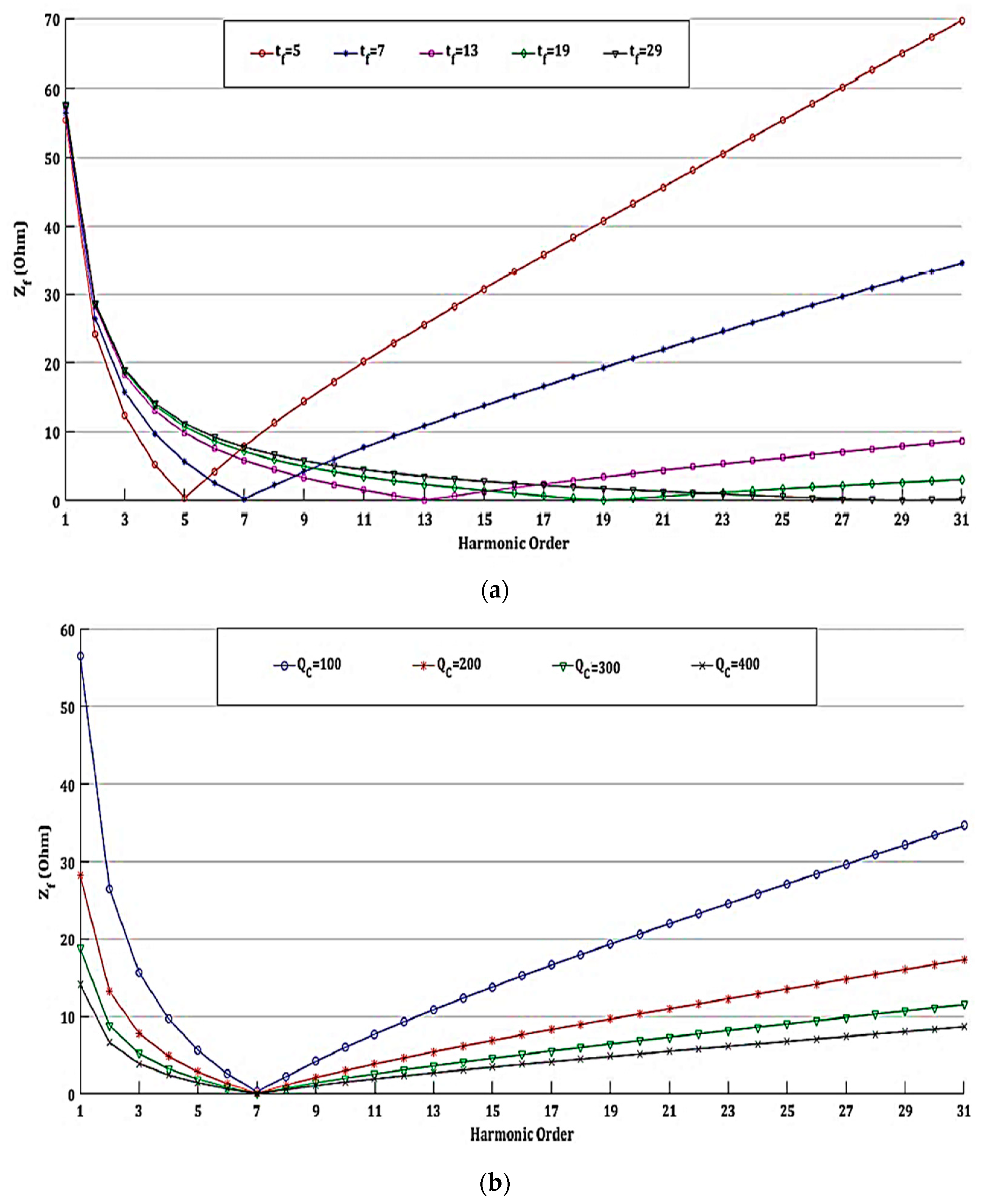
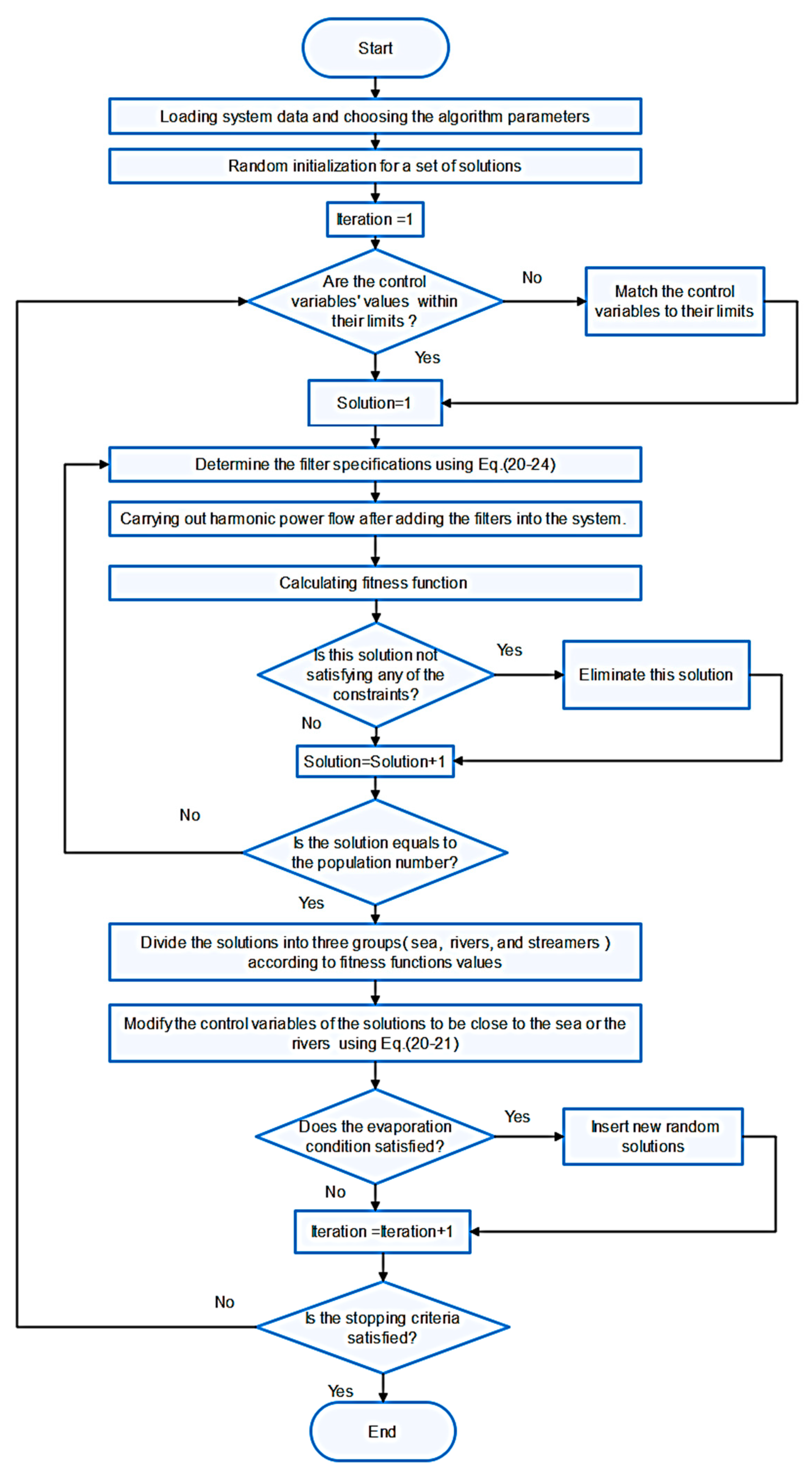
4. Proposed Filters Planning Procedure

Figure 6 shows the flowchart that describes the planning procedure of the STF. Where, the proposed filter planning procedure for harmonic mitigation has the following steps:
Step 1: Randomly initialize the initial set of raindrops that has a size of Npop.
R P = { 1 N pop [ f i l t e r 1 p l a c e f i l t e r n p l a c e f i l t e r 1 f t f i l t e r n f t f i l t e r 1 Q c f i l t e r n Q c ]
Step 2: Checking the following constraints:
f t [ 3 5 7 25 ]
where ft is the tuned harmonic order.
B u s _ 2 f i l t e r p l a c e N
Q c min Q c Q c max
Step 3: Evaluate the fitness of each raindrop by the following steps:
Calculating filter parameters which consist of (series of R, L, and C)
X C = ( V b a s e ) 2 Q C F
where Xc is the capacitive reactance and Q C F is the capacitor reactive power rating in kVAr.
X L = X C ( f t ) 2
where XL is the inductive reactance.
R = L / C Q F
L = X L 2 π f 0
C = 1 2 π f 0 X C
where QF is the quality factor of the filter, and f0 is the fundamental harmonic frequency.
(1)
Carrying out harmonic power flow calculation based on the backward/forward sweep power flow for balanced radial distribution feeders [35], Power flow analyses are carried before and after adding the filters into the system.
(2)
Calculating fitness function using the harmonic power flow results.
(3)
Checking the buses’ voltage, THD, and IHD constraints. If any solution doesn’t satisfy any of the constraints, putting the value of its fitness function equals infinity. So, it will not be selected as a minimum solution.
Step 4: Getting the personal best data and storing its controlled variables data as:
P b e s t   = min ( f i t n e s s   f u n c t i o n   m a t r i x )
Step 5: Applying the WCA to generate a new set of solutions.
Step 6: Repeating steps from 2 to 5 till reaching the maximum iterations number.
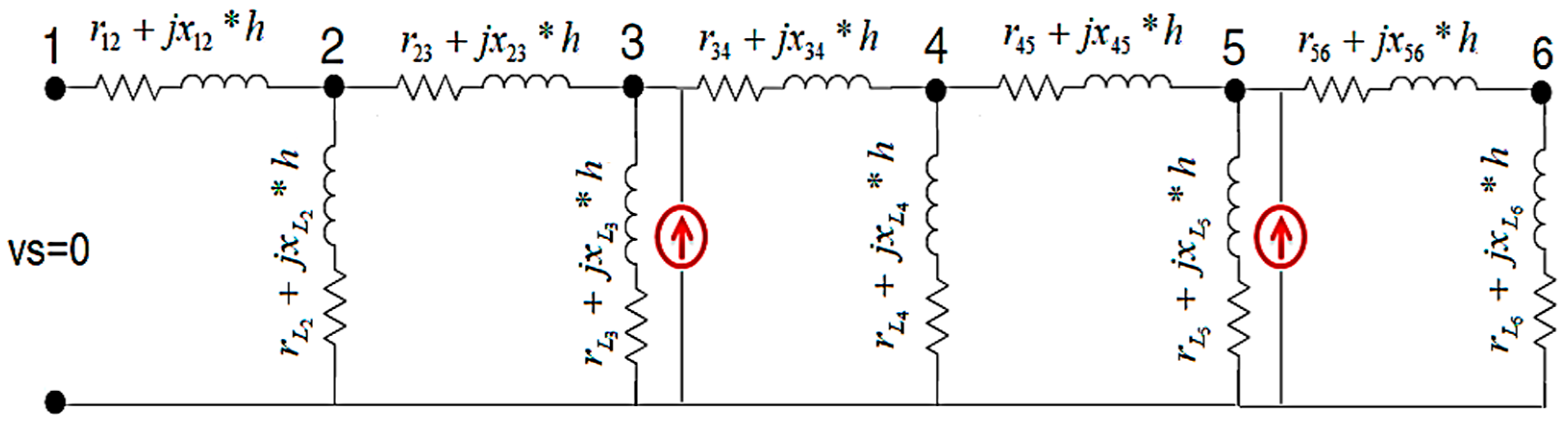
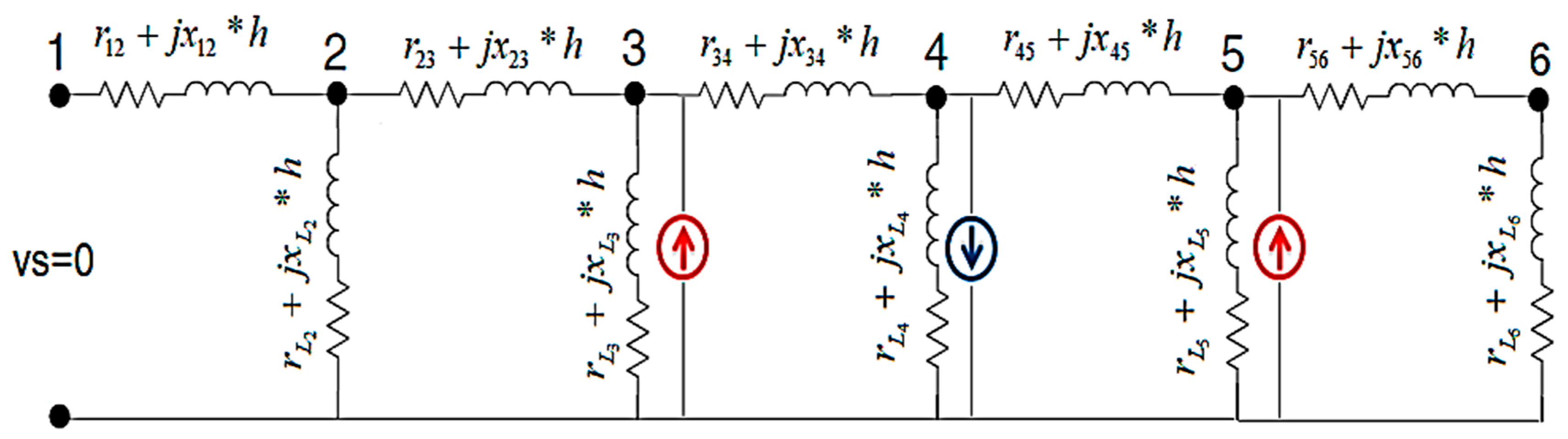
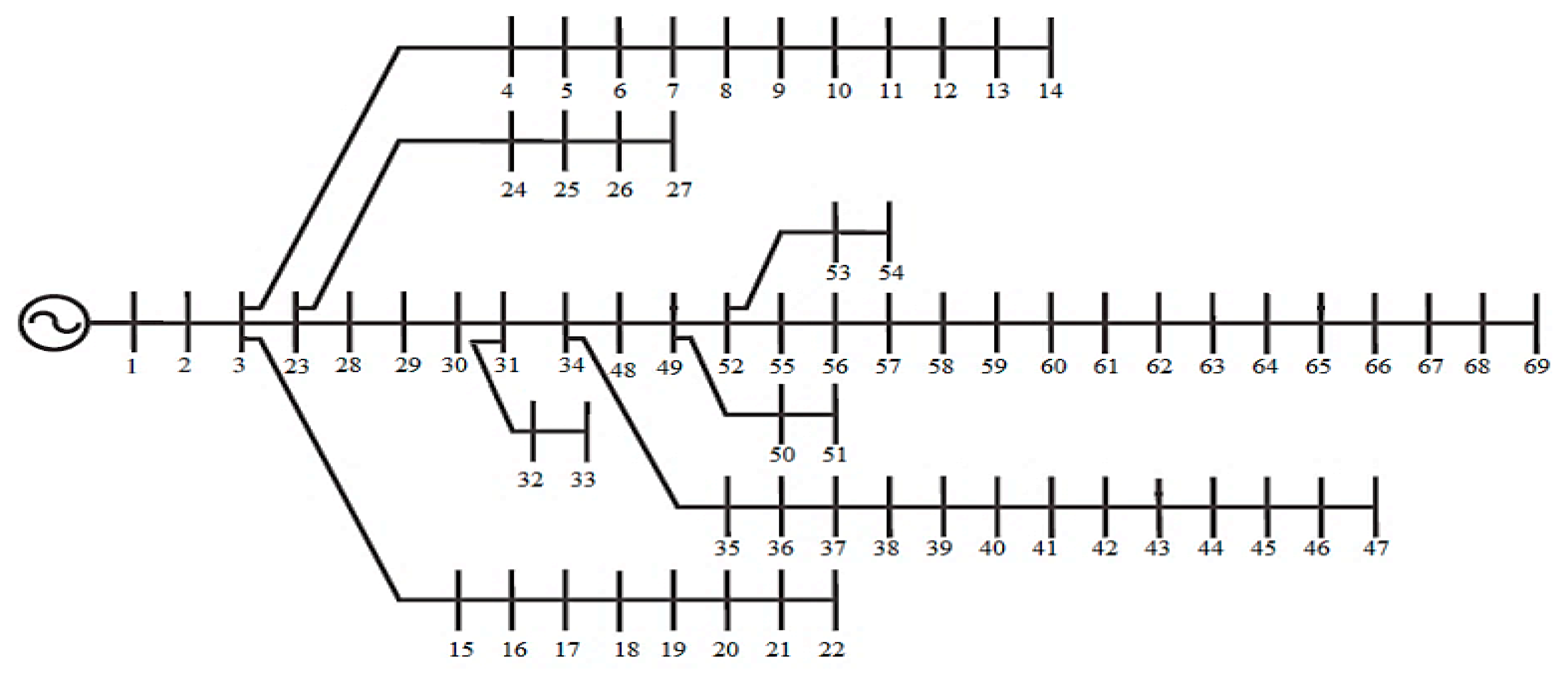
5. Applications

The proposed method is applied according to two cases studied as follows:
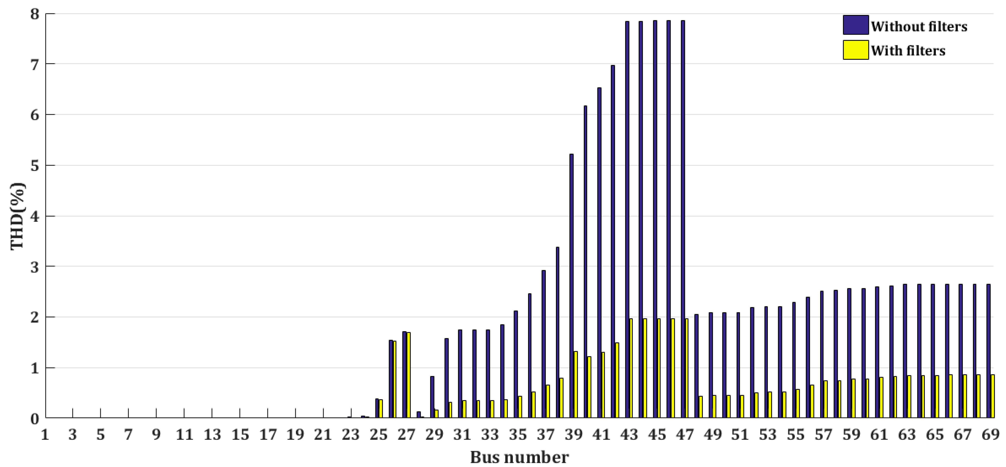
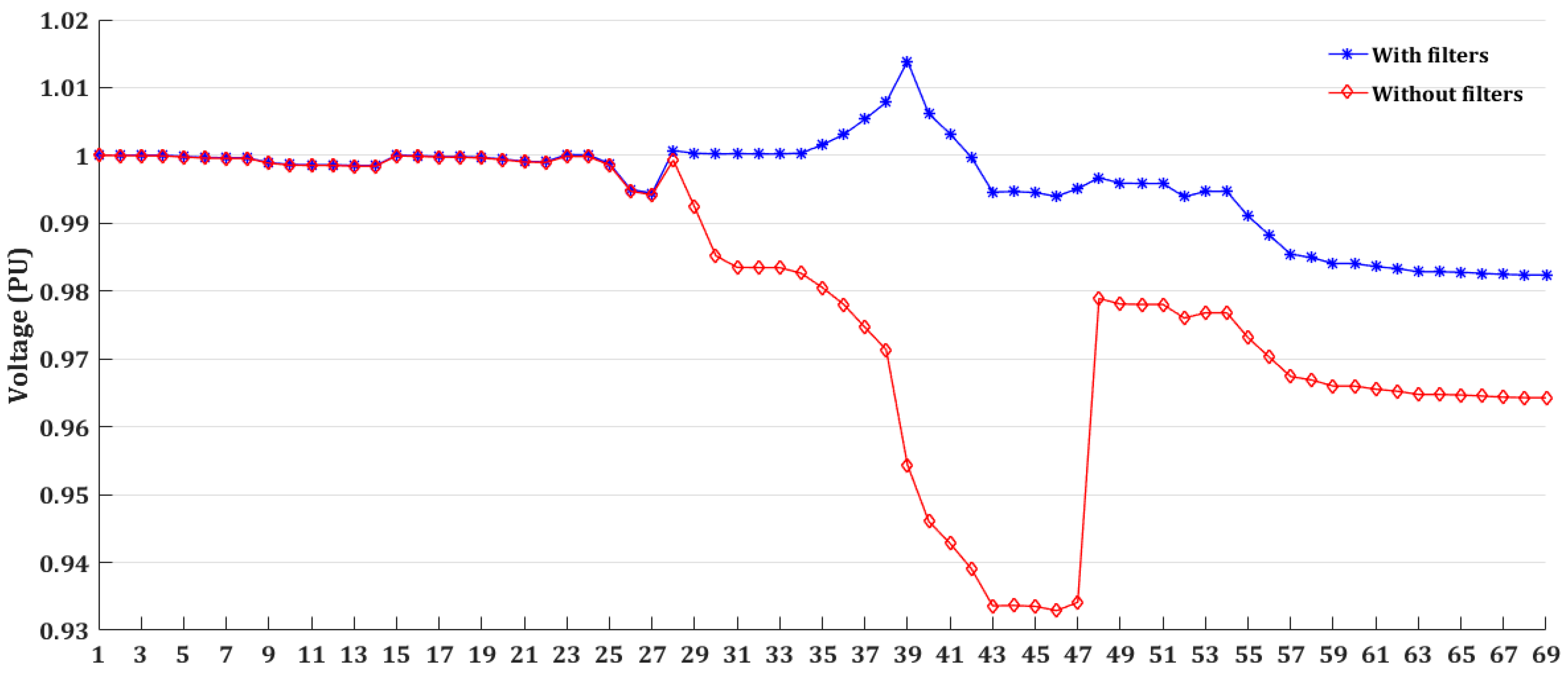
Case 1: Optimal planning of single-tuned filters without considering the harmonic spectrum of the DG units.
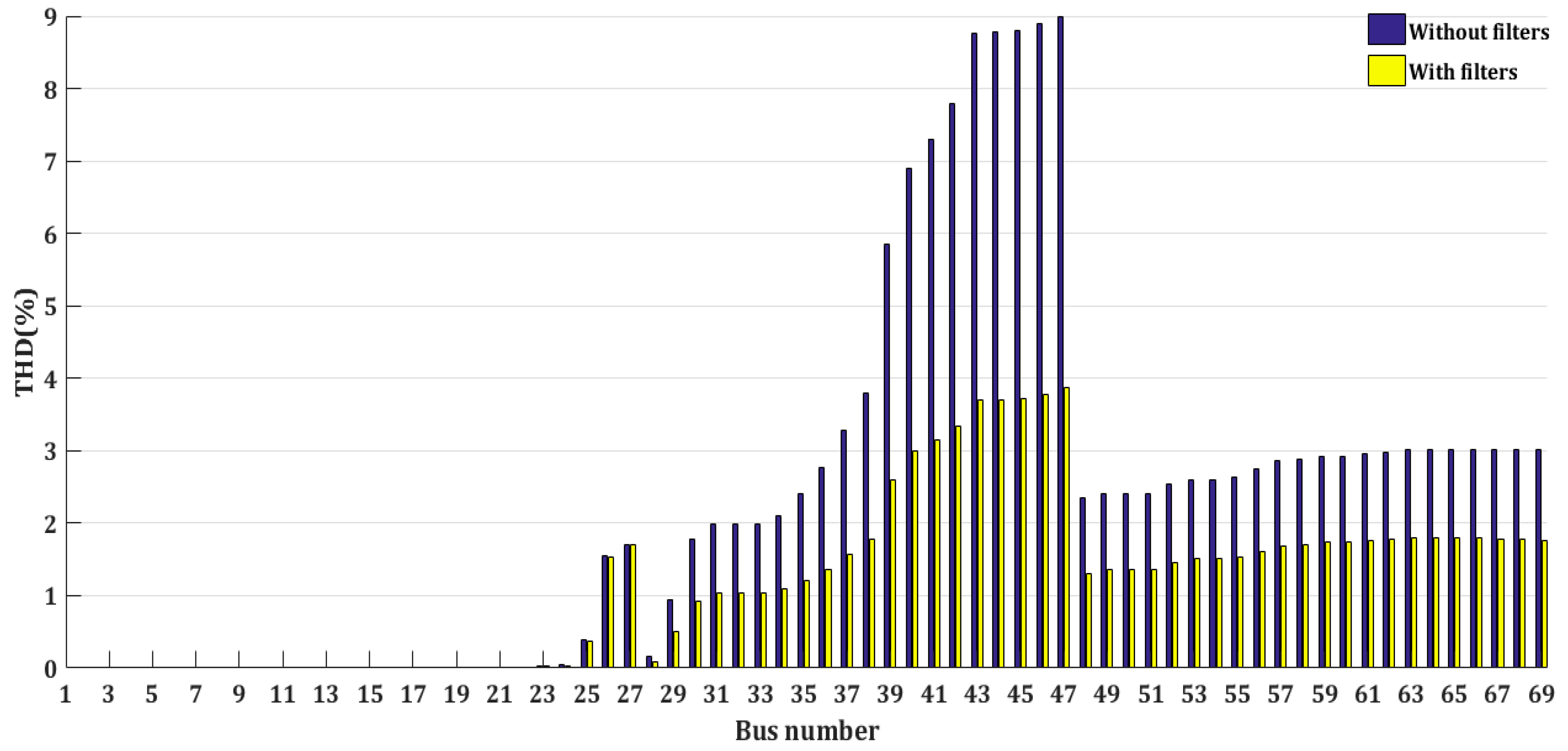
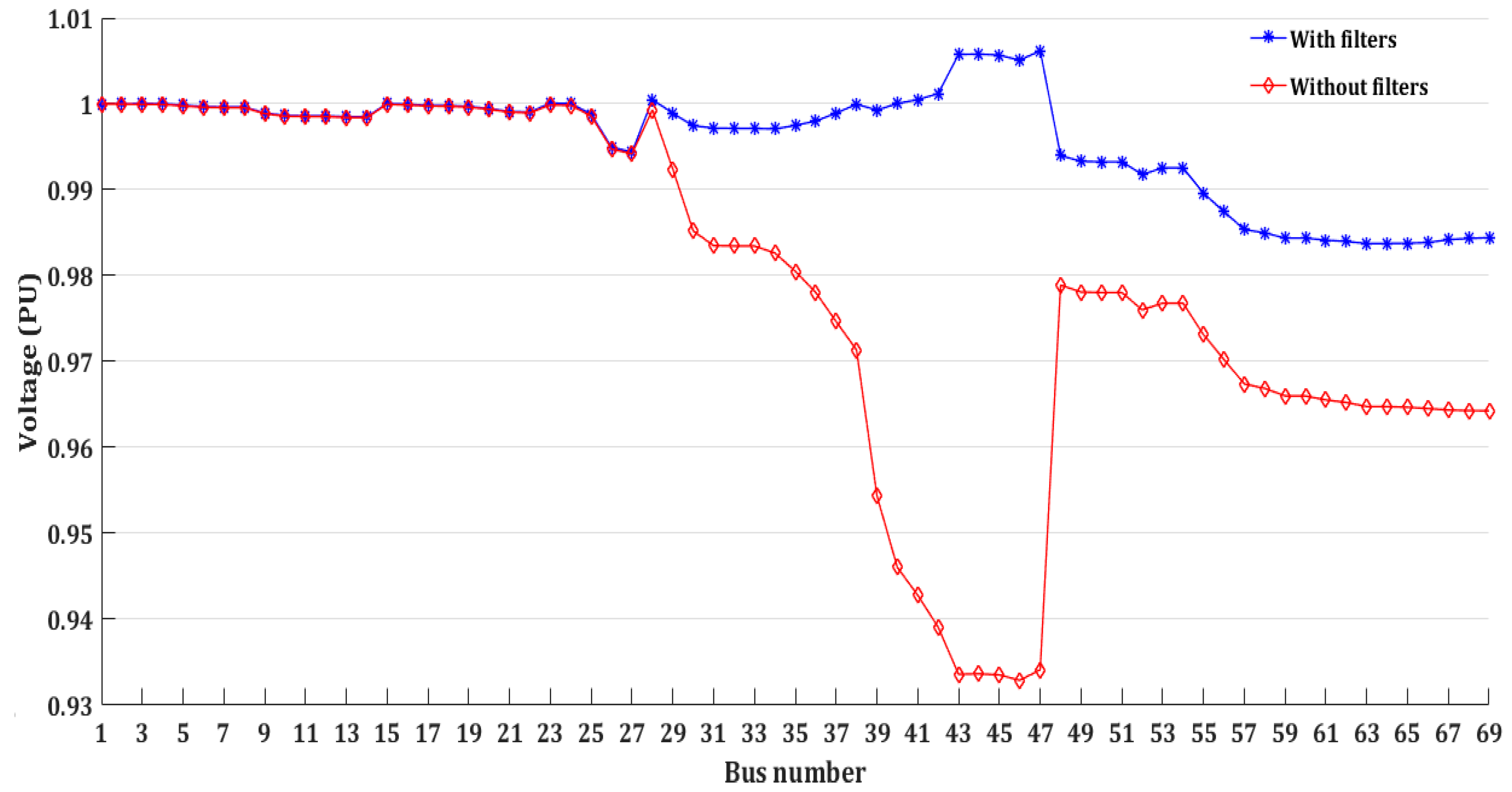
Case 2: Optimal planning of single tuned filters with considering the harmonic spectrum of the DG units.
The type of nonlinear load is assumed to be a six-pulse inverter that has a harmonic spectrum as shown in Table 1 [30]. The harmonic spectrum of the inverter-based DGs is also considered as shown in Table 2 [28]. DGs are placed nearby the heavy loads to reduce the power losses and improve the voltage profile [9]. For considering a high penetration of DGs, the total capacity of the DGs is assumed to be 40% of the total demand and divided equally into four units. The proposed method considered all the odd harmonic orders from 3rd up to the 25th harmonic order.
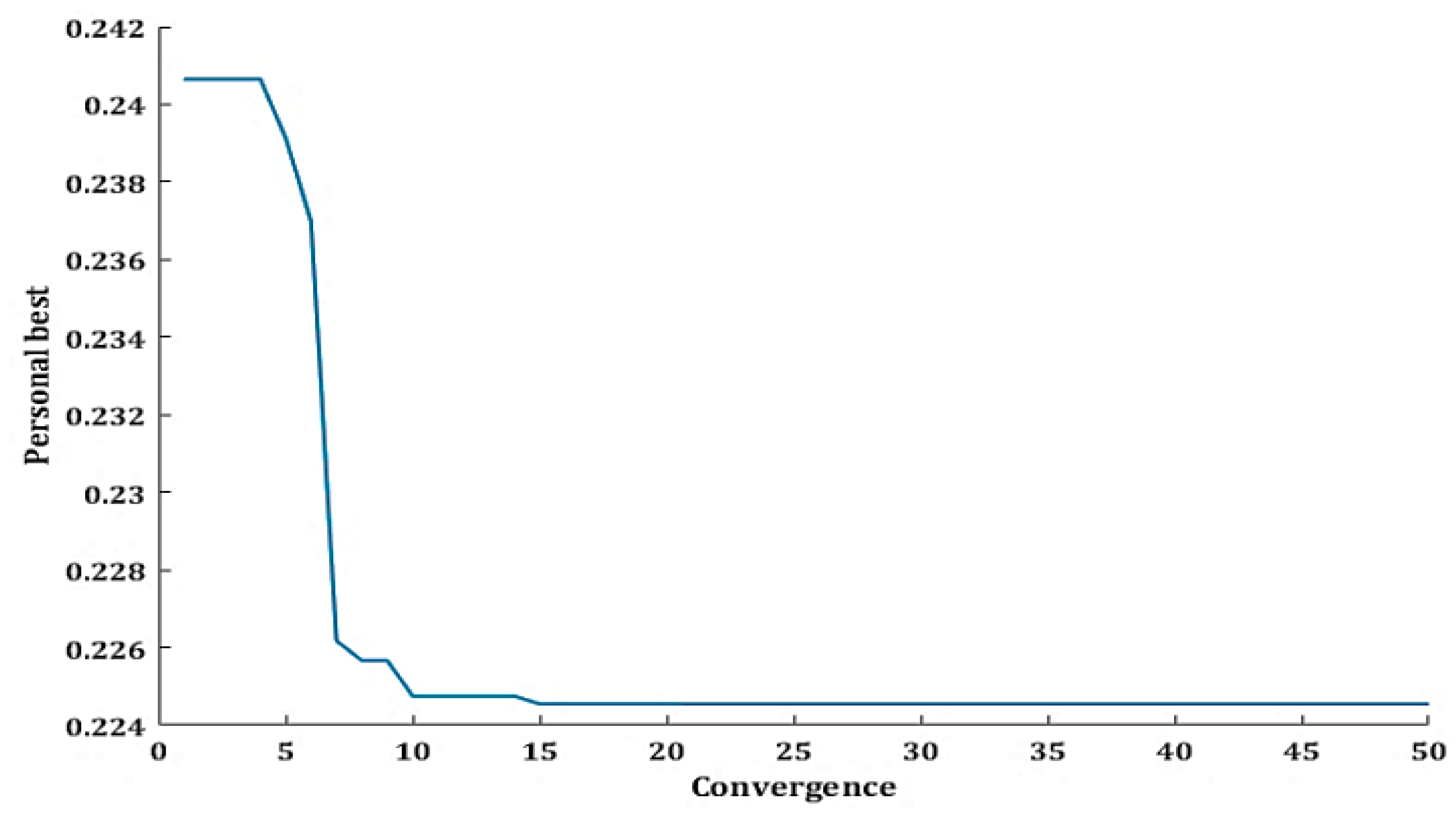
The weighting factors k1, k2, and k3 are considered equal to 0.5, 0.3, and 0.2, respectively. The WCA is implemented in MATLAB software using m-file code taking the total initial number of raindrops equals to 100 (one sea, 9 rivers, and 90 streamers). The evaporation condition dmax is considered to be 1 × 10⁻⁴, and the iterations number is 50.

6. Simulation Results and Discussion

6.1. Test Distribution Systems

The proposed method is applied to the modified IEEE 69-bus distribution system [9]. The total active and reactive loads of the original system are 3.802 MW and 2.694 MVAR, respectively. Six nonlinear loads are added and located at buses (12, 26, 27, 28, 43, 49, 53, and 63) in the system shown in Figure 7. Four DG units are also considered to be installed at buses (28, 44, 47, and 53) each one has a capacity equals to (190.1 + j 134.7) kVA.

6.2. Simulation Results of Case 1

The results of the filter planning in the first case are shown in Table 3 and Table 4. The results show that the proposed method reduced effectively the maximum THD from 7.87% to 2% to meet the IEEE-519 standard. As obtained in Table 3, the 7th order harmonic filter with a large size (Qc) was chosen for solving the system harmonic distortion problem. Based on the concept shown in Figure 5, the filter passband increases with increasing the filter capacitive reactive power and increasing the order of tuned frequency. Therefore, the 7th order harmonic filter has more flatten impedance characteristics curve rather than the 5th order filter. Furthermore, the capacity of the selected filter is 2.33 MVAR, which indicates a very flat characteristics curve. Therefore, only one filter tuned at the 7th order can mitigate both 5th, 7th, and other harmonic orders and keep the THD within the permissible limits.
The objective functions’ values, which are obtained in Table 4, show that the system minimum voltage has improved from 0.93 PU to 0.98 PU. The system power loss has also reduced from 51.5 to 29.8 kW. Moreover, the three considered objective functions have minimized using the proposed algorithm, which approves the ability of the proposed method to achieve multi-dimensional goals (technical and economic).
The convergence curve of the WCA is shown in Figure 8. It shows the convergence speed of the WCA, and how it can reach the personal best within a few iterations. The THD of the system buses before and after using the filters are shown in Figure 9. Where the maximum THD decreased significantly from about 8% to 2% to not only meet the standard limit but also, considered as a preventive action to keep the system harmonic within limits during any future increase in the system harmonics.
Figure 10 shows that the installed filters can improve the system voltage profile and keep all the buses’ voltages within the permissible limits. As it can be seen that many bus voltages (bus 40–bus 47) were out of limits before installing the filter.

6.3. Simulation Results of Case 2

Table 5 and Table 6 show the filter planning results for Case 2 considering the harmonic spectrum of DGs. The results show that two single tuned filters are optimally designed and planned to eliminate the third harmonic order. Table 5 shows the characteristics and parameters of the proposed filters. Table 6 illustrates the effect of the proposed filter planning in enhancing system performance (reducing the voltage deviation, power loss, and THD). Where these filters can reduce the maximum THD from 9% to 3.87% to meet the IEEE-519 standard. The power loss is also reduced from 54 to 32 kW.
The THD of the system buses before and after applying the proposed method is shown in Figure 11. This figure shows that; the DG units’ harmonics have a considerable effect in increasing the THD of the system. Where the system max. THD has increased by 13.9% due to considering the DGs harmonic spectrum. Moreover, the system voltage profile is improved due to the installation of the proposed filters as shown in Figure 12. Where all the buses’ voltages become within the permissible limits and the under-voltage issue is solved.

7. Conclusions

The optimal planning of passive single tuned harmonic filter in distorted distribution systems has been proposed in this paper. The proposed method considers the harmonic content resulted from the inverter-based DG units in the distribution system. The optimal planning problem has been solved using WCA with the aid of fundamental and harmonic backward/forward sweep power flow. The simulation results approved the effectiveness of the proposed method in determining the optimal design, number, and placement of the single tuned filter in the radial distribution system. The results also indicate that the harmonic spectrum of the DG units should be considered while designing the harmonic filters in the system to prevent increasing harmonic distortion in the system.
The noticeable findings of this paper are:
  • The effectiveness of the proposed filter planning method in achieving multi-dimensional objectives with the aid of WCA.
  • The WCA is efficient with good convergence characteristics in simultaneously determining the optimal design, placement, and the number of the STF.
  • The proposed method not only reduces the THD and improves the voltage profile but also reduces the power loss and filter costs.
  • Inverter-based DGs have shown a considerable effect on the harmonic distortion in distribution systems which increases the THD by about 14%.
  • By using the proposed method, THD in a 69-bus system has reduced by 75% without considering the harmonic distortion of the DGs, and reduced by 56.5% without considering the harmonic distortion of the DGs.
The future work will be directed to consider passive filter overcurrent and overvoltage, besides considering different renewable energy sources.

Author Contributions

A.S.A. and E.S.A. designed the idea strategy, studied the data, and wrote the manuscript. M.M.F.D. and K.M. revised and proofread the manuscript and designed some figures. Finally, R.A.E.-S., A.A.E.-E., and M.L. reviewing, editing, and supporting different improvements for the manuscript. All authors have read and agreed to the published version of the manuscript. All authors have contributed to the preparation of this manuscript.

Funding

This work was supported by the Department of Electrical Engineering and Automation, Aalto University, Espoo, Finland.

Institutional Review Board Statement

Not applicable.

Informed Consent Statement

Not applicable.

Data Availability Statement

The data presented in this study are available on request from the corresponding author.

Conflicts of Interest

The authors declare no conflict of interest.

References

  1. Solatialkaran, D.; Zare, F.; Saha, T.K.; Sharma, R. A Novel Approach in Filter Design for Grid-Connected Inverters Used in Renewable Energy Systems. IEEE Trans. Sustain. Energy 2020, 11, 154–164. [Google Scholar] [CrossRef]
  2. Shukl, P.; Singh, B. Delta-Bar-Delta Neural-Network-Based Control Approach for Power Quality Improvement of Solar-PV-Interfaced Distribution System. IEEE Trans. Ind. Inform. 2020, 16, 790–801. [Google Scholar] [CrossRef]
  3. IEEE. IEEE Recommended Practices and Requirements for Harmonic Control in Electrical Power Systems; Institute of Electrical and Electronics Engineers (IEEE): New York, NY, USA, 1993; IEEE Std 519-1992. [Google Scholar]
  4. Almohaimeed, S.; Abdel-Akher, M. Power Quality Issues and Mitigation for Electric Grids with Wind Power Penetration. Appl. Sci. 2020, 10, 8852. [Google Scholar] [CrossRef]
  5. Sakar, S.; Balci, M.E.; Aleem, S.H.A.; Zobaa, A.F. Increasing PV hosting capacity in distorted distribution systems using passive harmonic filtering. Electr. Power Syst. Res. 2017, 148, 74–86. [Google Scholar] [CrossRef] [Green Version]
  6. Li, L.; Mu, H.; Li, N.; Li, M. Economic and environmental optimization for distributed energy resource systems coupled with district energy networks. Energy 2016, 109, 947–960. [Google Scholar] [CrossRef]
  7. El Ela, A.A.A.; El-Sehiemy, R.A.; Shaheen, A.M.; Shalaby, A.S. Application of the crow search algorithm for economic environmental dispatch. In Proceedings of the IEEE 2017 Nineteenth International Middle East Power Systems Conference (MEPCON), Cairo, Egypt, 19–21 December 2017; pp. 78–83. [Google Scholar]
  8. El-Ela, A.A.A.; El-Sehiemy, R.A.; Abbas, A.S. Optimal Placement and Sizing of Distributed Generation and Capacitor Banks in Distribution Systems Using Water Cycle Algorithm. IEEE Syst. J. 2018, 12, 3629–3636. [Google Scholar] [CrossRef]
  9. Shaheen, A.M.; El-Sehiemy, R.A.; Farrag, S.M. A novel adequate bi-level reactive power planning strategy. Int. J. Electr. Power Energy Syst. 2016, 78, 897–909. [Google Scholar] [CrossRef]
  10. Hu, H.; Shi, Q.; He, Z.; He, J.; Gao, S. Potential Harmonic Resonance Impacts of PV Inverter Filters on Distribution Systems. IEEE Trans. Sustain. Energy 2014, 6, 151–161. [Google Scholar] [CrossRef]
  11. Langella, R.; Testa, A.; Meyer, J.; Moller, F.; Stiegler, R.; Djokic, S.Z. Experimental-Based Evaluation of PV Inverter Harmonic and Interharmonic Distortion Due to Different Operating Conditions. IEEE Trans. Instrum. Meas. 2016, 65, 2221–2233. [Google Scholar] [CrossRef] [Green Version]
  12. Abaza, A.; Fawzy, A.; El-Sehiemy, R.A.; Alghamdi, A.S.; Kamel, S. Sensitive reactive power dispatch solution accomplished with renewable energy allocation using an enhanced coyote optimization algorithm. Ain. Shams Eng. J. 2020. [Google Scholar] [CrossRef]
  13. Hernández-Mayoral, E.; Iracheta-Cortez, R.; Lecheppe, V.; Salgado, O.A.J. Modelling and Validation of a Grid-Connected DFIG by Exploiting the Frequency-Domain Harmonic Analysis. Appl. Sci. 2020, 10, 9014. [Google Scholar] [CrossRef]
  14. Shafik, M.B.; Chen, H.; Rashed, G.I.; El-Sehiemy, R.A.; Elkadeem, M.R.; Wang, S. Adequate Topology for Efficient Energy Resources Utilization of Active Distribution Networks Equipped with Soft Open Points. IEEE Access 2019, 7, 99003–99016. [Google Scholar] [CrossRef]
  15. Shaheen, E.A.M.; El-Sehiemy, R.A.; Abdelaziz, A.Y. Equilibrium optimization algorithm for net-work reconfiguration and distributed generation allocation in power systems. Appl. Soft Comput. 2021, 98, 106867. [Google Scholar] [CrossRef]
  16. Abbas, A.S.; Ali, E.S.; El-Sehiemy, R.A.; El-Ela, A.A.A.; Fetyan, K.M. Comprehensive Parametric Analysis of Single Tuned Filter in Distribution Systems. In Proceedings of the IEEE 2019 21st International Middle East Power Systems Conference (MEPCON), Cairo, Egypt, 17–19 December 2019; pp. 465–472. [Google Scholar]
  17. Khan, U.N.; Sidhu, T.S. A Phase-Shifting Transformer Protection Technique Based on Directional Comparison Approach. IEEE Trans. Power Deliv. 2014, 29, 2315–2323. [Google Scholar] [CrossRef]
  18. Bai, S.; Lukic, S.M. New Method to Achieve AC Harmonic Elimination and Energy Storage Integration for 12-Pulse Diode Rectifiers. IEEE Trans. Ind. Electron. 2012, 60, 2547–2554. [Google Scholar] [CrossRef]
  19. Boontua, S.; Chaithanakulwat, A.; Savangboon, T. Power Quality Improvement with Mitigation of Harmonic Distortion in Three-phase System Based on Shunt Active Power Filter Mechanism. Int. J. Eng. Appl. 2019, 7, 188. [Google Scholar] [CrossRef]
  20. Zeineldin, H.; Zobaa, A. Particle Swarm Optimization of Passive Filters for Industrial Plants in Distribution Net-works. Electr. Power Compon. Syst. 2011, 39, 1795–1808. [Google Scholar] [CrossRef]
  21. Ertay, M.M.; Tosun, S.; Zengin, A.; Tosun, S. Simulated annealing based passive power filter design for a medium voltage power system. In Proceedings of the IEEE 2012 International Symposium on Innovations in Intelligent Systems and Applications, Trabzon, Turkey, 2–4 July 2012; pp. 1–5. [Google Scholar]
  22. El-Ela, A.A.; Allam, S.; El-Arwash, H. An optimal design of single tuned filter in distribution systems. Electr. Power Syst. Res. 2008, 78, 967–974. [Google Scholar] [CrossRef]
  23. Chang, G.W.; Wang, H.-L.; Chuang, G.-S.; Chu, S.-Y. Passive Harmonic Filter Planning in a Power System with Considering Probabilistic Constraints. IEEE Trans. Power Deliv. 2008, 24, 208–218. [Google Scholar] [CrossRef]
  24. Stone, P.E.C.; Wang, J.; Shin, Y.-J.; Dougal, R.A. Efficient Harmonic Filter Allocation in an Industrial Distribution System. IEEE Trans. Ind. Electron. 2011, 59, 740–751. [Google Scholar] [CrossRef]
  25. Au, M.; Milanovic, J. Planning Approaches for the Strategic Placement of Passive Harmonic Filters in Radial Dis-tribution Networks. IEEE Trans. Power Deliv. 2007, 22, 347–353. [Google Scholar] [CrossRef]
  26. Chang, Y.-P.; Low, C.; Hung, S.-Y. Integrated feasible direction method and genetic algorithm for optimal planning of harmonic filters with uncertainty conditions. Expert Syst. Appl. 2009, 36, 3946–3955. [Google Scholar] [CrossRef]
  27. Mohammadi, M.; Rozbahani, A.; Montazeri, M. Multi criteria simultaneous planning of passive filters and dis-tributed generation simultaneously in distribution system considering nonlinear loads with adaptive bacterial foraging opti-mization approach. Int. J. Electr. Power Energy Syst. 2016, 79, 253–262. [Google Scholar] [CrossRef]
  28. Ghaffarzadeh, N.; Sadeghi, H. A new efficient BBO based method for simultaneous placement of inverter-based DG units and capacitors considering harmonic limits. Int. J. Electr. Power Energy Syst. 2016, 80, 37–45. [Google Scholar] [CrossRef]
  29. Kawann, C.; Emanuel, A. Passive shunt harmonic filters for low and medium voltage: A cost comparison study. IEEE Trans. Power Syst. 1996, 11, 1825–1831. [Google Scholar] [CrossRef]
  30. El-Sayed, M.M.; El-Ela, A.A.; El-Sehiemy, R.A. Effect of photovoltaic system on power quality in electrical distribution networks. In Proceedings of the IEEE Eighteenth International Middle East Power Systems Conference (MEPCON), Cairo, Egypt, 27–29 December 2016; pp. 1005–1012. [Google Scholar]
  31. Eajal, A.A.; El-Hawary, M.E. Optimal Capacitor Placement and Sizing in Unbalanced Distribution Systems with Harmonics Consideration Using Particle Swarm Optimization. IEEE Trans. Power Deliv. 2010, 25, 1734–1741. [Google Scholar] [CrossRef]
  32. Leite, J.C.; Abril, I.P.; Azevedo, M.S. Capacitor and passive filter placement in distribution systems by non-dominated sorting genetic algorithm-II. Electr. Power Syst. Res. 2017, 143, 482–489. [Google Scholar] [CrossRef]
  33. Eskandar, H.; Sadollah, A.; Bahreininejad, A.; Hamdi, M. Water cycle algorithm—A novel metaheuristic optimization method for solving constrained engineering optimization problems. Comput. Struct. 2012, 110–111, 151–166. [Google Scholar] [CrossRef]
  34. Kersting, W. Distribution System Modeling and Analysis, 4th ed.; CRC Press: Boca Raton, FL, USA, 2018. [Google Scholar]
  35. Teng, J.-H.; Chang, C.-Y. Backward/Forward Sweep Based Harmonic Analysis Method for Distribution Sys-tems. IEEE Trans. Power Deliv. 2007, 22, 1665–1667. [Google Scholar] [CrossRef]
Figure 1. Simple radial distribution system under a specified harmonic frequency.
Applsci 11 00774 g001
Figure 2. Filter representation as a constant impedance load in the system.
Applsci 11 00774 g002
Figure 3. Filter representation as a constant current source in the system.
Applsci 11 00774 g003
Figure 4. Thevenin equivalent circuit of the system at resonance conditions.
Applsci 11 00774 g004
Figure 5. Impact of filter parameters on its characteristics curve; (a) effect of tf and (b) effect of Qc.
Applsci 11 00774 g005
Figure 6. Flowchart of the planning procedure.
Applsci 11 00774 g006
Figure 7. IEEE 69-bus distribution test system.
Applsci 11 00774 g007
Figure 8. Convergence curve of the Water Cycle Algorithm (WCA).
Applsci 11 00774 g008
Figure 9. Total harmonic distortion (THD) of the 69-bus system buses with and without filters in case 1.
Applsci 11 00774 g009
Figure 10. Fundamental voltage profile of the 69-bus system with and without filters in case 1.
Applsci 11 00774 g010
Figure 11. THD of the 69-bus system buses with and without filters in case 2.
Applsci 11 00774 g011
Figure 12. The fundamental voltage of the 69-bus system buses with and without filters in case 2.
Applsci 11 00774 g012
Table 1. Harmonic spectrum of six-pulse nonlinear loads.
Harmonic Order157111317192325
Value (%)1004214.37.93.23.72.32.31.4
Table 2. Harmonic spectrum of the inverter-based DGs.
Harmonic OrderMagnitude %Phase (deg.)Harmonic OrderMagnitude %Phase (deg.)
1100−2.3498140.36
320−15.2911565.54
515−20.7413342.62
710−30.85152153.28
Table 3. Results of control variables for filter planning in case 1.
Filter No.PlacementftQc (MVar)R (Ω)L (mH)C (µF)
13972.33030.06550.0015138.84
Table 4. Results of objective functions of case 1.
ParameterWithout FilterWith Filter
Vmax (p.u)11.0139
Vmin (p.u)0.93290.9824
Ploss (kW)51.56129.83
THDmax (%)7.872
Fitness Functions
F1F2F3Ftotal
1.96790.45452.8657 × 1040.2284
Table 5. Results of control variables for filter planning in case 2.
Filter No.PlacementftQc (MVar)R (Ω)L (mH)C (µF)
16930.13.56170.18906
24331.820.19520.0104108.7
Table 6. Results of objective functions of case 2.
ParameterWithout FilterWith Filter
Vmax (p.u)11.0062
Vmin (p.u)0.93290.9837
Ploss (kW)53.62232.29
THDmax (%)93.87
Fitness Functions
F1F2F3Ftotal
3.86570.41313.0866 × 1040.3076
Publisher’s Note: MDPI stays neutral with regard to jurisdictional claims in published maps and institutional affiliations.

