Hybrid Metal/Polymer Filaments for Fused Filament Fabrication (FFF) to Print Metal Parts


1
Department of Civil Engineering and Architecture, University of Catania, Viale Andrea Doria 6, 95125 Catania, Italy
2
Department of Chemical Engineering Materials Environment, Sapienza—Università di Roma and UdR INSTM, Via Eudossiana 18, 00184 Roma, Italy
*
Author to whom correspondence should be addressed.
Appl. Sci. 2021, 11(4), 1444; https://doi.org/10.3390/app11041444
Submission received: 4 January 2021
/
Revised: 25 January 2021
/
Accepted: 2 February 2021
/
Published: 5 February 2021
(This article belongs to the Special Issue Design, Synthesis and Characterization of Hybrid Composite Materials)
Abstract
:Featured Application
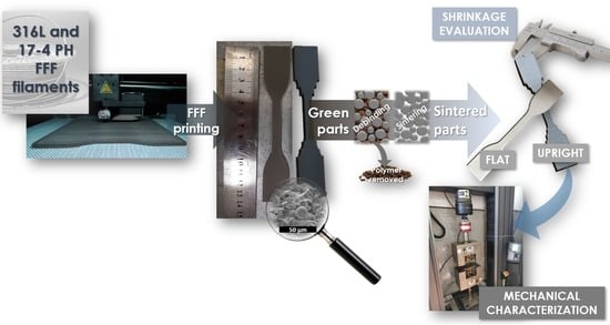
The development of hybrid metal/polymer filaments opens the possibility to expand metal 3D printing with investment costs accessible to small and medium enterprises. This will allow 3D printing of metal parts with the same approach used for desktop 3D printing, thus further democratizing the use of additive manufacturing in applications that cannot be fulfilled by polymeric 3D printing.
Abstract
The exploitation of mechanical properties and customization possibilities of 3D printed metal parts usually come at the cost of complex and expensive equipment. To address this issue, hybrid metal/polymer composite filaments have been studied allowing the printing of metal parts by using the standard Fused Filament Fabrication (FFF) approach. The resulting hybrid metal/polymer part, the so called “green”, can then be transformed into a dense metal part using debinding and sintering cycles. In this work, we investigated the manufacturing and characterization of green and sintered parts obtained by FFF of two commercial hybrid metal/polymer filaments, i.e., the Ultrafuse 316L by BASF and the 17-4 PH by Markforged. The Scanning Electron Microscopy (SEM) and Energy Dispersive X-ray Spectrometry (EDS) analyses of the mesostructure highlighted incomplete raster bonding and voids like those observed in conventional FFF-printed polymeric structures despite the sintering cycle. A significant role in the tensile properties was played by the building orientation, with samples printed flatwise featuring the highest mechanical properties, though lower than those achievable with standard metal additive manufacturing techniques.
1. Introduction
Additive manufacturing (AM) has gained an increasing importance not only as a technology for prototyping but, due to its latest developments, it is now used for production of functional parts. Metal AM is widely accepted to produce aerospace parts [1], medical prosthetics [2], automotive parts [3] etc. Several technologies for metal AM are available such as direct metal laser sintering (DMLS), selective laser melting (SLM), laser-engineered net shaping (LENS), electron beam melting (EBM), binder jetting (BJ), etc. Most of these technologies use metal powders as feedstocks and sources of high energy to melt or sinter the metal powder to 3D print objects [4]. These techniques require high investments for machine purchase and complex facilities to work safely with metal powders. The investment costs for traditional approaches limited the use of metal AM to specific fields where the return on investment justified its use.
Recently, several companies developed lower cost approaches in the attempt to democratize metal additive manufacturing by using hybrid metal/polymer feedstocks processed using standard polymeric AM techniques. In these cases, debinding and sintering cycles were applied on green printed parts to remove the polymeric binder and to obtain fully dense metal objects. The AM manufacturing techniques used so far are fused filament fabrication or vat photopolymerization. In the first case, metal/polymer filaments or rods are printed with FFF-like printers to obtain the green part. Desktop Metal Inc, Markforged Inc and Nanoe systems rely on this approach. Other companies, like Pollen AM and AIM3D GmbH, patented machines processing pellets directly like those used for Metal Injection Molding (MIM). Admatec, Incus and Photocentric Ltd. are developing metal AM using photopolymerizable resins highly filled with metal particles.
The seminal works that introduced the use of FFF with metal filled filaments date to the 1990s when Fused Deposition of Metals (FDMet) was first presented [5,6,7]. However, only recently this process has received increasing interest with some papers addressing the use of different metals. Among all of them, two types of stainless steels were investigated: 316L and 17-4 PH.
Kurose et al. [8] studied the effects of different building orientations for 316L printed parts using their own filament. All the parts were printed with a rectilinear infill pattern and at 100% infill density varying the layer thickness. The highest density for the green printed part was 92.9% with a layer thickness of 0.1 mm. The sintered parts showed anisotropic behavior with shrinkage degree varying between 15 and 17% and with the highest shrinkage along the layer direction. Higher shrinkage values were reported in other studies with values between 15 and 23% [9]. The specimens printed up-right displayed the lowest values for the Ultimate Tensile Strength (i.e.,100 MPa), while the highest values (i.e., 453 MPa) were shown by samples printed flatwise and on the edge. The large difference was explained as the result of the voids laying perpendicular to the tensile direction for the upright specimens. No data on the tensile modulus were reported. Gong et al. [9] printed their specimens using the filament Ultrafuse 316L, measuring a residual porosity around 1.5%, which contrasted to the fully dense structure obtained by SLM. The sintered specimens showed equiaxed grains and austenitic microstructure such as those shown during annealing. The yield strength measured was 167 MPa while UTS (Ultimate Tensile Strength) was 465 MPa and the tensile modulus 152 GPa. All these values were lower than those measured for samples manufactured by SLM and for those reported with AISI 316 L. The low mechanical properties were explained as the results of the porosity which also caused a lower ductility (i.e., 31%) compared to standard annealed AISI 316 L (i.e., 60%). Thompson et al. [10] focused on the characterization of the flexural behavior for 316L filaments produced on their own. They used over-extrusion to produce high green body density samples. After sintering the porosity varied from 1.9% to 1.4%, depending on the sintering temperature used. In this paper EDX (Energy Dispersive X-Ray Spectroscopy) analysis revealed that the grain boundary phase is Cr23C6, which is thought not to impact on corrosion but, due to carbide presence, to result in the embrittlement of the sintered part. The mechanical properties showed a reduction of about 20% compared to a rolled sheet made of 316L. These findings were explained as caused by the presence of porosity and the high grain size after sintering.
The studies on FDM printing of 17-4 PH filled filaments are limited. In 2018 Gonzales-Gutierrez et al. [11] studied the 3D printing conditions for filaments produced internally. The sintered parts produced therefrom were also characterized in following papers. The average Young’s modulus was determined to be 196 GPa, the average maximum stress was 696 MPa and the strain at break 4% [12]. The printed specimens showed an average porosity of 4.3% after sintering but the different batches showed also great variation in terms of strain at break. In a recent paper, the mechanical properties of the green parts were optimized by varying the 3D printing parameters [13]. Galati and Minetola [14] recently reported a detailed study on the density, roughness and dimensional accuracy of sintered parts printed using 17-4 PH filaments with the ADAM (Atomic Diffusion Additive Manufacturing) process patented by Markforged.
In this paper two hybrid metal/polymer systems were evaluated: the Ultrafuse 316L by BASF and the 17-4 PH system by Markforged. The sintered parts were characterized in terms of their tensile properties analyzing the mesostructure of the green and sintered parts by Scanning Electron Microscopy coupled with Energy-dispersive X-ray spectroscopy. The results were compared with analogous metals printed using standard 3D printing metal technologies. The need for this study arose from the increasing use of such materials on commonly used printers. Therefore, we intended to expand the study by using a low-cost printer for the Ultrafuse 316L that has not been reported before as the standard parameters given by BASF have been obtained on Ultimaker series machines. In addition to that, a detailed analysis of the mesostructure and of the influence of real load bearing area is reported in this paper.
2. Materials and Methods
The materials used were sourced from commercial producers. For the 17-4 PH system the technology developed by Markforged was used, while for the filaments filled with 316L the Ultrafuse 316L produced by BASF was chosen.
The Ultrafuse 316L filament is a metal–polymer composite with a nonslip surface, allowing application in any Bowden or direct-drive extruder. In this paper, we used a desktop-size 3D printer model M200 by Zortrax (Zortrax S.A., Olsztyn, Poland) equipped with a 0.4 mm bronze nozzle. The printing conditions used for the Ultrafuse 316L were adapted from those specified by BASF in their technical data sheet testing on a calibration cube (see video S1) [15]. The printing settings are reported in Table 1. The 3D-printed samples were outsourced to a debinding and sintering service for postprocessing as recommend by BASF.
The 17-4 PH samples were printed and sintered in outsourcing using a Metal X printer following the printing settings specified by Markforged. The part size and the whole ADAM process parameters, including the support structure, are designed automatically by proprietary software named Eiger. Eiger is a CAM (Computer Aided Manufacturing) software that manages the whole process from the design to the sintering phase. The software is closed to the user. Therefore, the process parameters are not known, and cannot be varied by the user, except for the layer thickness and the building orientation. Flatwise and upright building orientation were tested. The deposition strategy used by Markforged includes one outer contour and three inner ones as reported by Galati and Minetola [14] (Figure S1). Like in standard FFF systems, the bottom and the top layers are printed with full density, while the strategy used for the other layers depends on the layer thickness. For the layer thickness of 0.050 mm a full-density strategy is used, while a closed triangular cell path is followed to infill the section for the higher layer thickness of 0.125 mm.
The Ultrafuse 316L filament and all the printed green parts were analyzed by Scanning Electron Microscopy (SEM) using a SEM EVO by Zeiss. The sintered parts were analyzed using a MIRA3 by Tescan. All the samples containing polymers were gold sputtered before SEM analysis. The software Image J was used to analyze the SEM pictures to evaluate the mesostructure of the sintered parts.
3. Results and Discussion
First, an in-depth analysis of the filament and of the green printed parts is presented. The sintered parts are then analyzed focusing on the mesostructure obtained after sintering and relating the mechanical properties with the structure obtained.
3.1. Filament and Green Parts
3.1.1. Characterization of the Ultrafuse 316L Filament
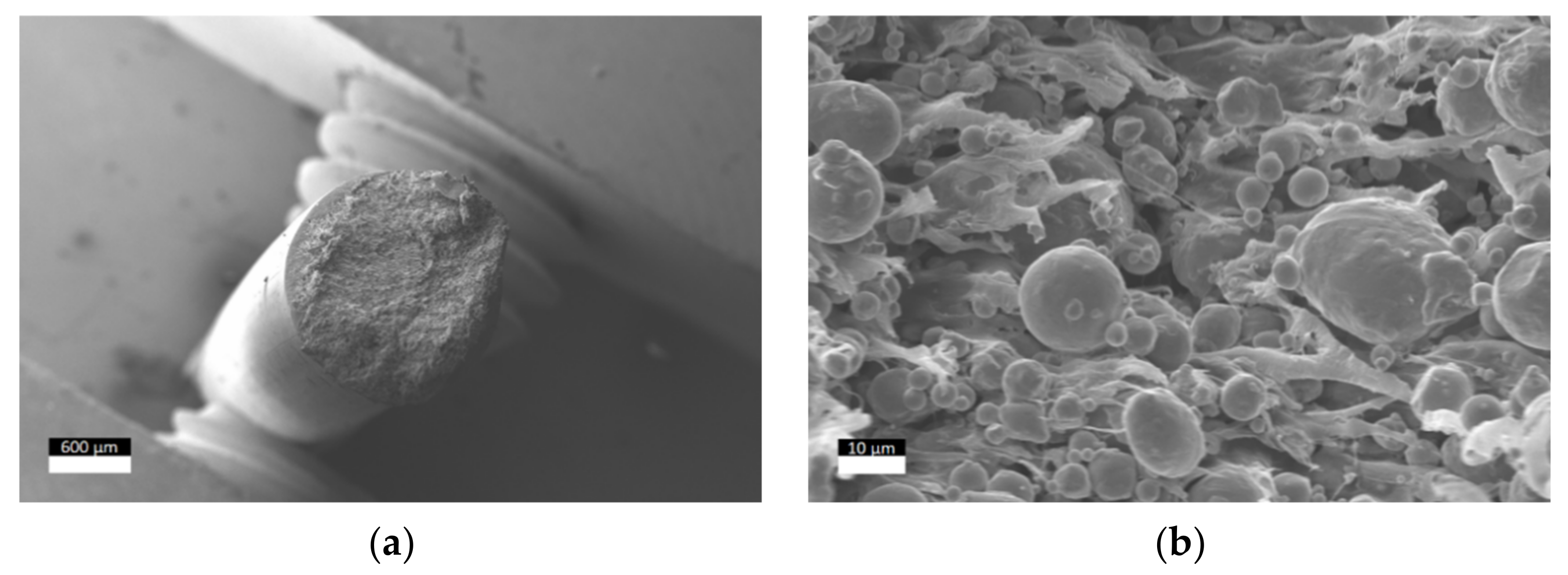
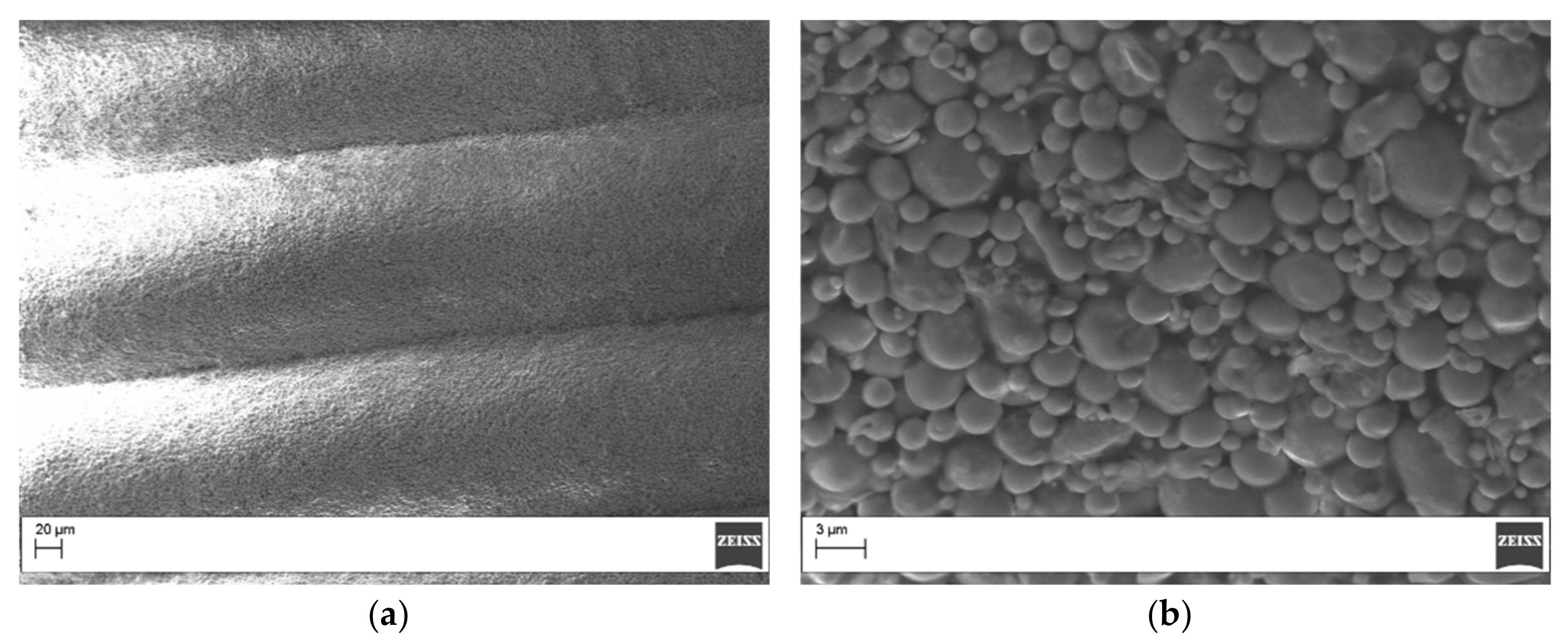
The Ultrafuse 316L filament was fractured and analyzed under the microscope. The filament showed a layered structure with an external polymeric coating layer (Figure 1a) that allowed the preparation of a flexible filament that can be bent with no breakage. The internal structure is composed of metal particles with dimensions varying from 10 µm to 1 µm fully embedded in polymeric strands (Figure 1b). The metal particles appeared coated with a thick coating.
3.1.2. Characterization of the Green Parts
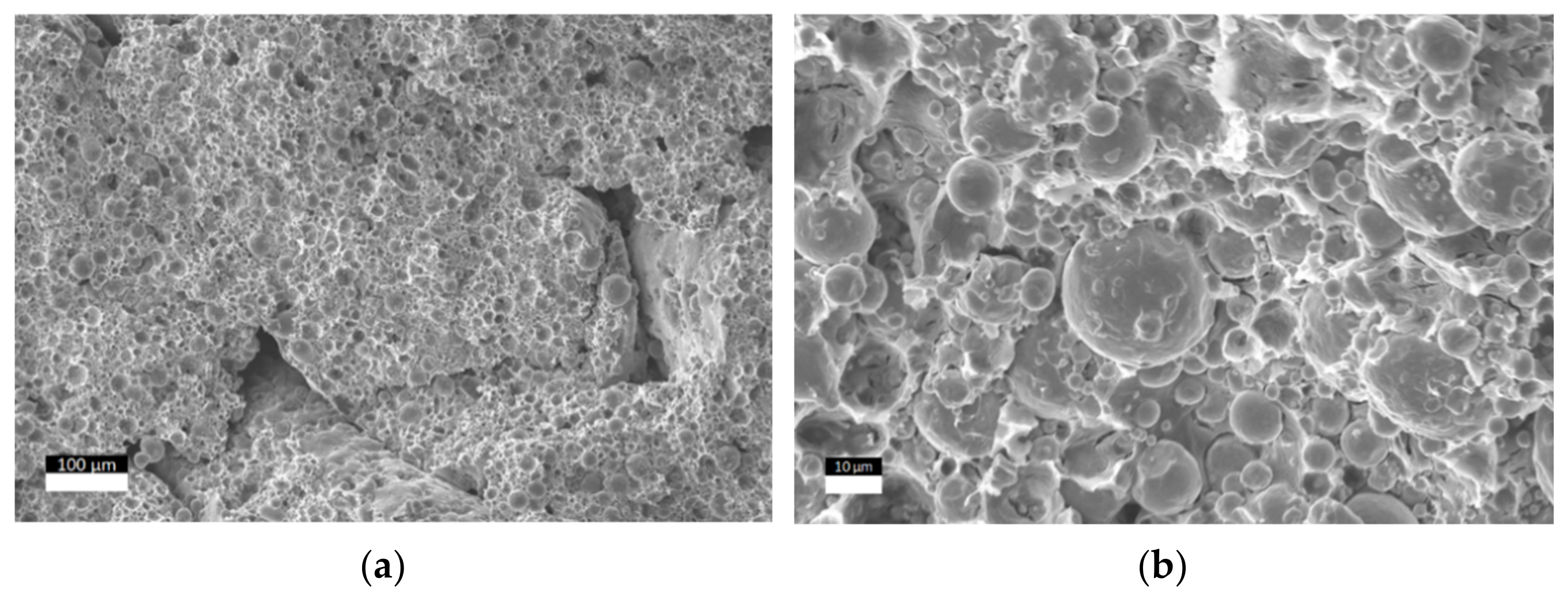
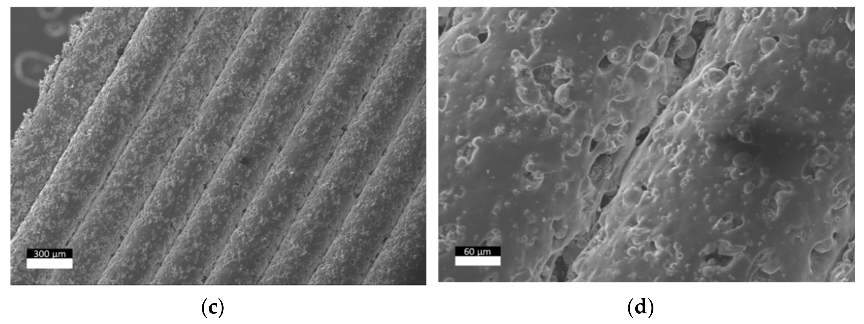
The 316L green parts were printed using a 100% infill density. However, some voids existed between the deposited rasters due to incomplete fusion (Figure 2a). The polymeric strands clearly visible in the neat filament (Figure 1b) were not observed in the printed specimens (Figure 2b) as a result of the polymer matrix melting and diffusion during the printing step. However, the coated layer was still present as it can be observed when looking at the contour side of the green samples (Figure 2c,d). The mesostructure obtained is like those observed in standard FFF samples and the part’s consistency relied on the bonding between each raster resulting from the melting of the external coating and of the internal polymeric strands. For comparison purposes, the same analyses were performed on the 17-4 PH green printed sample using the ADAM process by Markforged. In this case the rasters appeared more compacted and with a higher interdiffusion (Figure 3a). However, rasters appeared dry and with no clear evidence of polymeric matrix between the particles, which displayed smaller dimensions (5–0.5 µm) compared to those observed in the Ultrafuse 316L system (Figure 3b). As a result of this mesostructure, the 17-4 PH green samples were too brittle to carry out any reliable mechanical characterization and even for handling. On the contrary, the Ultrafuse 316L green parts were easy to handle.
3.2. Sintered Parts
3.2.1. Dimensional Analysis of the Sintered Parts
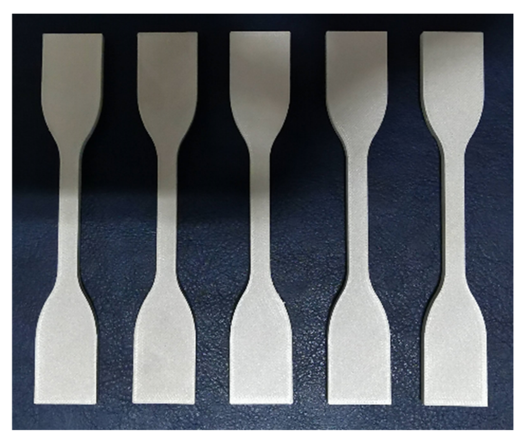
The use of hybrid polymer/metal for 3D printing metal relies on the removal of the polymeric binder upon the debinding/sintering cycles for the MIM technology. The polymer removal and the particles’ sintering resulted in the part’s shrinkage. Exemplary sintered parts are shown in Figure 4.
The 3D printed parts need to be overdesigned considering the dimensional variations through the entire process. For these reasons, comparing the part’s dimensions before and after sintering is important to understand the correct part design. Table 4 reports the measured values for the green and sintered parts for the build orientations used. The flatwise specimens showed a linear shrinkage of approximately 20% in the XY plane while higher values (i.e., 25.20%) where measured in the Z direction perpendicularly to the layer direction. The samples printed upright showed higher anisotropic behavior with values ranging from 8.57% to 20.70%. The anisotropic behavior is controlled by the effect of gravity on the metal part during the sintering process. Kurose et al. [8] reported linear shrinkage values which varied with the building orientation between 14% and 23%. Gong et al. [9] reported similar shrinkage values but they also noted that features at a lower height shrank less than the same feature at a higher height. The values measured in this paper are different compared to the shrinkage parameters declared by BASF in their guidelines [15]. An explanation for this difference could be the mesostructure of the green parts that, as shown in Figure 2, was not fully dense. Similar tests could not be performed on the 17-4 PH samples as those samples were printed with proprietary settings and delivered already sintered.
3.2.2. Tensile Test of the Sintered Parts
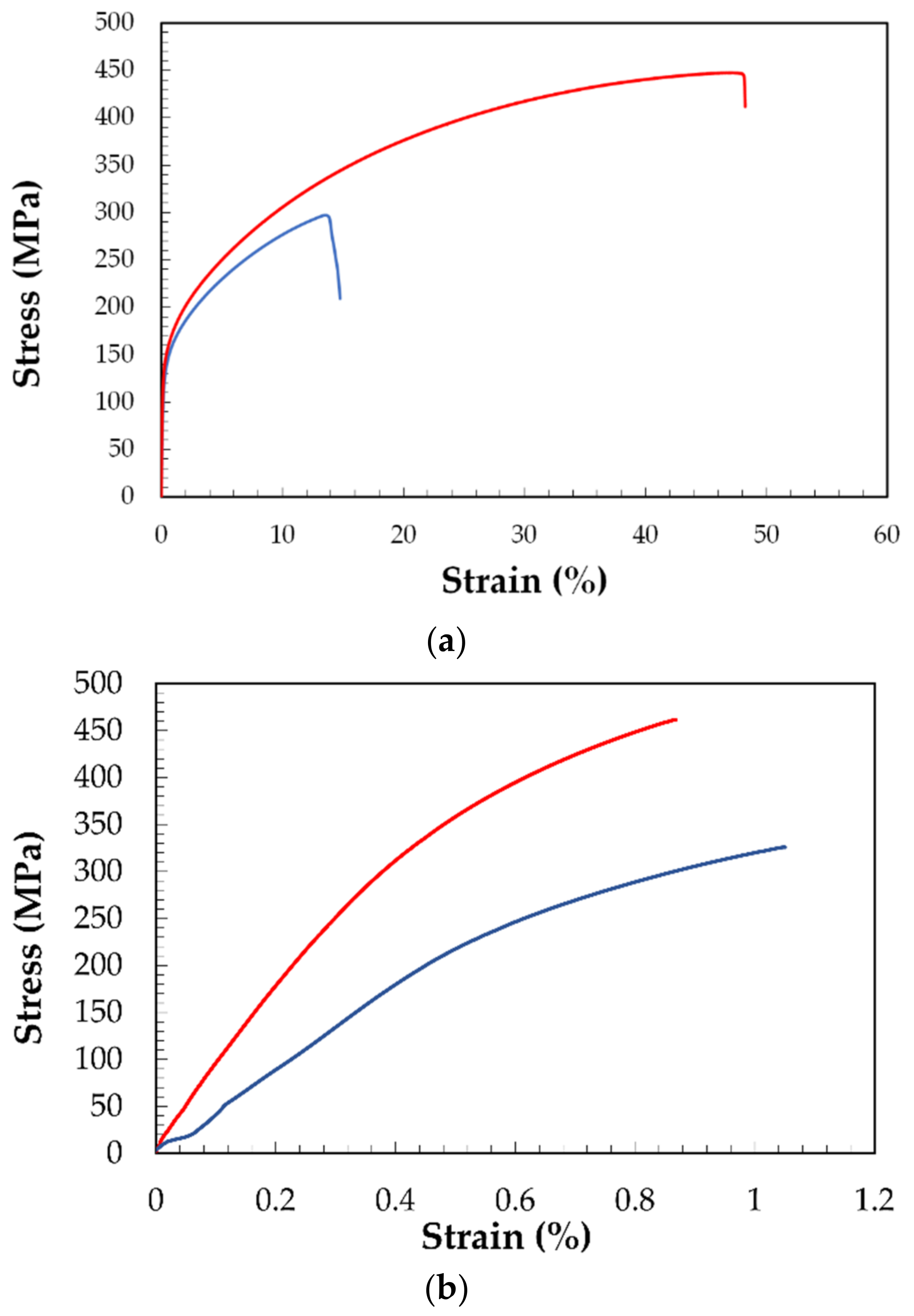
The sintered parts were tested in tensile mode. Exemplary curves for the samples printed with the Ultrafuse 316L and the Markforged 17-4 PH are shown in Figure 5. The data refer to the stress calculated as load divided by the nominal area Width*Thickness (Table 2 and Table 3). The 316 L samples showed higher strain at break values (i.e., ≈43%) compared to the 17-4 PH samples (below 1%). The tensile properties measured for sintered 316L and 17-4 PH are summarized in Table 5. The properties declared by the filaments’ manufacturers are also reported for comparison purposes.
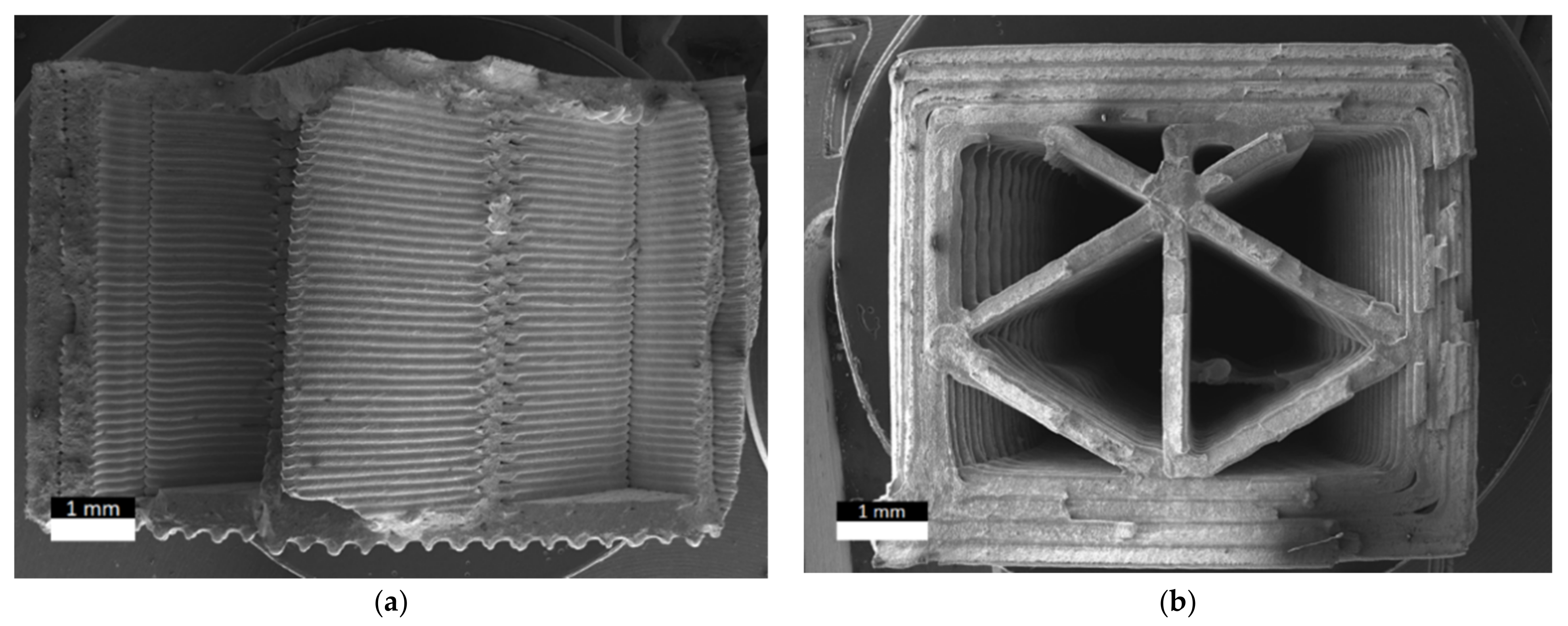
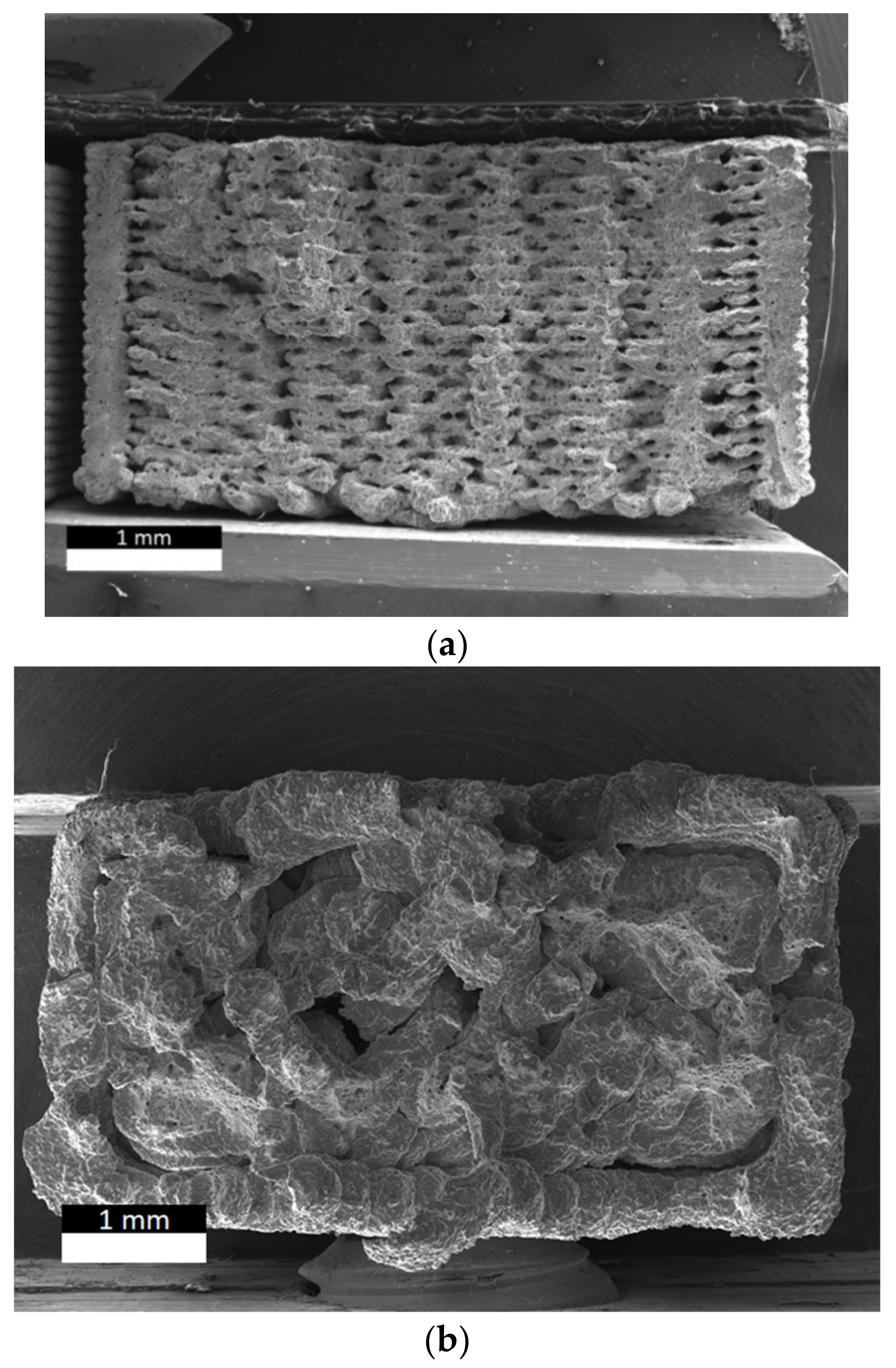
It is clear from Table 5 that the measured properties for the 17-4 PH samples are lower compared to those reported by Markforged. However, these specimens presented a closed triangular cell infill [14] which resulted in a lower load bearing area (Figure 6). The cross-section area was estimated using Image J to be equal to 20.89 mm2 rather than 36 mm2 which was calculated considering the external sides of the cross section. If the real load bearing area (20.89 mm2) is considered, the tensile properties were higher and close to those reported by Markforged (Table 6). Desktop Metal has also released some values for their 17-4 PH system (Table 5) that lie in between the values found in this paper and those declared by Markforged. In the open literature, Gonzales-Gutierrez et al. [12] for their lab-made filament filled with 55 v% of 17-4 PH metal particles and printed with a 100% infill density reported a tensile modulus between 174 GPa and 208 GPa, while the maximum stress ranged from 660 MPa to 729 MPa. The wide range of the mechanical properties observed was explained as the result of the presence of defects in the structure of the specimens.
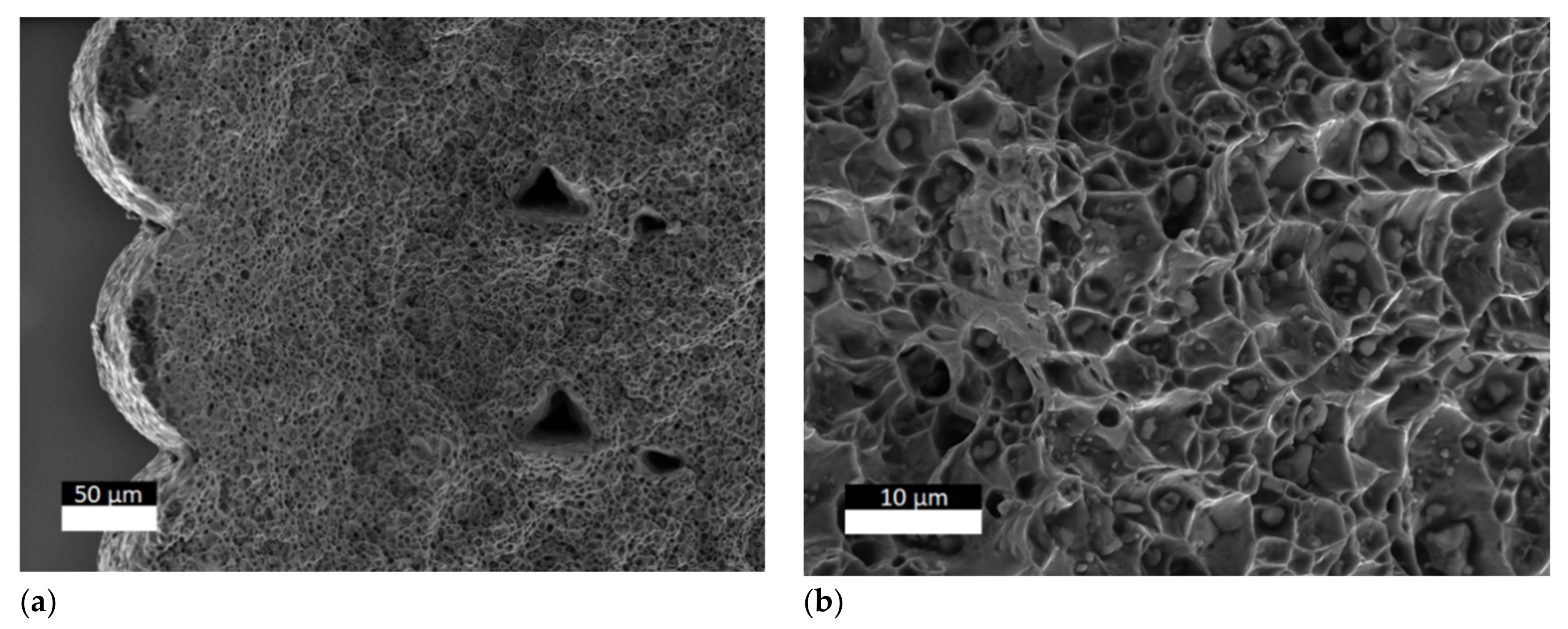
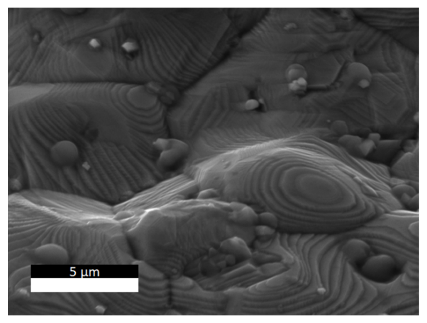
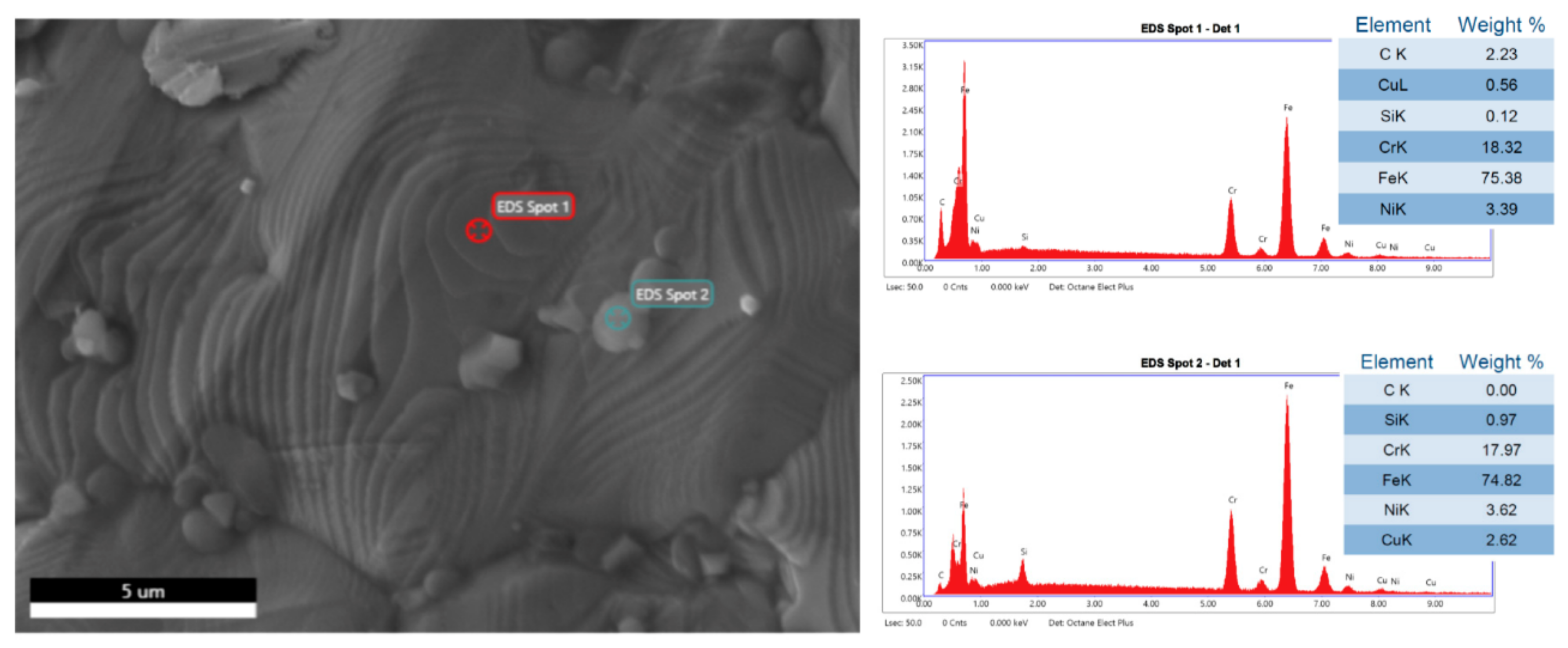
The fractured surface of the 17-4 PH samples characterized in this paper showed the presence of two types of defects: pores between the raster (Figure 7a) and the presence of inclusions (Figure 7b). The inclusions were observed on the raster’s surface too (Figure 8). The EDX analysis (Figure 9) showed the presence of a higher carbon concentration on the raster’s surface leading to the conclusion that the surface might be rich in carbon-based residues of the polymeric binder. The presence of these defects and the higher carbon concentrations can cause the reduced mechanical properties observed in our samples. It is also interesting to observe that the upright samples showed higher variability in the test data as demonstrated by the high standard deviation. Similar trends were observed for standard FFF when comparing flat versus upright printed samples [16] and it was explained as the result of the influence of the interlayer bonding strength. The 17-4 PH upright-printed samples clearly showed the presence of an interlayer fracture confirming that this building orientation is the worst in terms of mechanical resistance.
The 316L samples presented tensile properties closer to those declared by BASF but lower. The cross section of these samples was characterized. The mesostructure of the flatwise sample showed the presence of micro porosity between the rasters which is clearly visible despite the full sintering cycle (Figure 10a). This porosity seems the result of the incomplete fusion between the raster observed in the green part (Figure 2). The upright sample showed even bigger pores and, as for the 17-4 PH, the presence of an interlayer fracture (Figure 10b). Using Image J, the porosity of the flatwise sample was estimated to be equal to 9.76%, leading to an estimated real load bearing area of 17.07 mm2 rather than the measured 18.91 mm2. The tensile properties estimated with the real load bearing area were 174.15 GPa, 163.93 MPa and 491.65 MPa for the tensile modulus, yield strength and tensile strength, respectively. Despite the area correction, the measured values were still lower than those reported by BASF. This is the consequence of the porosity that could act as a stress intensifier leading to premature failure. Similar mechanical performance drops were observed when comparing FFF to injection molded counterparts [17,18,19]. The upright samples, due to the higher porosity and to the building orientation that led to high loading of the interlayer region, showed lower mechanical resistance compared to the flatwise samples. As for the 17-4 PH samples, higher standard deviations were observed for the upright building orientation.
3.2.3. Comparison with Standard Metal AM Technologies
The use of FFF for printing metal samples has been developed to have an easy, safe, and low-cost alternative to standard AM metal techniques. However, the mechanical performances are also important. Table 7 summarizes the mechanical properties for 316 L and 17-4 PH processed by standard metal AM and with no thermal post-processing applied. For comparison purposes the mechanical properties achieved using MIM were also reported. The specimens produced by FFF (Table 5) showed overall lower mechanical properties compared to analogous parts obtained by standard metal AM. For the 316L, the FFF manufactured specimens showed properties in the same range of MIM. Something similar was obtained for 17-4 PH if the real cross section areas (Table 6) were considered instead of the nominal areas. Therefore, the FFF parts manufactured by using hybrid metal/polymer filaments are better compared to MIM parts. However, to exploit the best performances, inherent defects due to processing, like voids and poor interlayer bonding (Figure 10), must be prevented. This can be achieved optimizing the printing settings [13]. Therefore, to fully exploit the potential of FFF applied to hybrid metal/polymer, more research into printing optimization is advisable. In addition to the simple tensile testing in a future work it will be important to characterize the effect of pre-crack on the printed specimens as this might have a relevant effect on applications [20].
Apart from mechanical performances, economic considerations must also be evaluated when comparing FFF of hybrid metal/polymer to standard metal AM. The manufacturing of a mold for injection molding (Figure 11) was considered as a reference part to compare the use of the Ultrafuse 316L with the production using a SLM EOS400m printing SSL316L. The cost modelling used is based on the model proposed by Ruffo et al. [27]. The results of cost simulations are reported in Table 8. The material cost was assumed to be 129 EUR/kg and 30 EUR/kg for the Ultrafuse 316L and the SSL316L, respectively. The cost simulation yielded a higher value for SLM (EUR 330.13) compared to FFF (EUR 100.62) because the recycling fraction (95%) for SLM operating only to print this mold yields a high waste of unused and not recyclable powder. The other cost that impacted significantly on the final part price was the machine usage (18.3%) as a result of the high investment cost for the EOS M400 (about 1.7 M€). The final predicted cost for printing the mold using FFF with the Ultrafuse 316L was EUR 246.13 versus the EUR 1147.88 predicted for SLM. In the case of the FFF this was the cost for the green part. To this cost must be added the cost for sintering that is currently priced around 60 EUR/kg by Elnik as the preferred partner of BASF. In addition, considering the price for sintering, the final cost is still much lower than the estimated cost for SLM.
4. Conclusions
Two commercial hybrid metal/polymer filaments were investigated for manufacturing, with an FFF approach, metal parts without using the expensive and complex equipment typically associated with standard additive manufacturing techniques for metals. The specimens were analyzed in their green and sintered state and the microstructural analysis by SEM allowed the unveiling of the presence of defects in the green state which resulted in voids and poor interlayer bonding in the sintered state. These defects caused a reduction in the tensile mechanical properties of the sintered parts compared to those declared by the materials’ manufacturers. Nevertheless, the final mechanical properties obtained using FFF were in the same range of those achieved by MIM.
The results of the mechanical characterization revealed that considerable gaps still exist compared to metals produced by standard metal AM techniques. However, it was demonstrated by cost modelling referring to a single mold prototype, that the use of hybrid metal/polymer filaments processed by FFF has a strong potential to allow printing of metal parts at a lower cost. This cost modelling did not account for the environmental impacts of the processes. However, as recently shown by some authors [28], the choice of the AM process can impact on the environment differently. For example, Giudice et al. [29] showed that SLM processing has a high energy consumption that might be overcome using hybrid metal–polymer filaments presented in this study, which can be processed by simple desktop FFF machines operated at much lower electric power.
Supplementary Materials
The following are available online at https://www.mdpi.com/2076-3417/11/4/1444/s1, Video S1: FFF printing of the Ultrafuse 316L.
Author Contributions
Conceptualization, G.C.; investigation, C.T., J.T.; resources, G.C.; data curation, C.T., J.T. and F.S.; writing—original draft preparation, G.C.; writing—review and editing, F.S. and J.T.; funding acquisition, G.C. All authors have read and agreed to the published version of the manuscript.
Funding
This research was funded by MIUR, grant number 20179SWLKA Project Title Multiple Advanced Materials Manufactured by Additive technologies (MAMMA), under the PRIN funding Scheme, Project Coordinator G.C. and under the funding scheme Change supported by the University of Catania Project Coordinator G.C.
Institutional Review Board Statement
Not applicable.
Informed Consent Statement
Not applicable.
Data Availability Statement
The data presented in this study are available on request from the corresponding author.
Acknowledgments
Claudio Tosto acknowledges the funding of his PhD by MIUR within the PON Ricerca e Innovazione 2014–2020 Asse I “Investimenti in Capitale Umano” -Azione I.1 “Dottorati Innovativi Con Caratterizzazione Industriale” Project Title “Advanced Materials by Additive manufacturing” (AMA).
Conflicts of Interest
The authors declare no conflict of interest.
References
- Frazier, W.E. Metal additive manufacturing: A review. J. Mater. Eng. Perform. 2014, 23, 1917–1928. [Google Scholar] [CrossRef]
- Liaw, C.Y.; Guvendiren, M. Current and emerging applications of 3D printing in medicine. Biofabrication 2017, 9. [Google Scholar] [CrossRef] [PubMed]
- Guo, C.; Zhou, L.; Lv, J. Effects of expandable graphite and modified ammonium polyphosphate on the flame-retardant and mechanical properties of wood flour-polypropylene composites. Polym. Polym. Compos. 2013, 21, 449–456. [Google Scholar] [CrossRef]
- DebRoy, T.; Wei, H.L.; Zuback, J.S.; Mukherjee, T.; Elmer, J.W.; Milewski, J.O.; Beese, A.M.; Wilson-Heid, A.; De, A.; Zhang, W. Additive manufacturing of metallic components—Process, structure and properties. Prog. Mater. Sci. 2018, 92, 112–224. [Google Scholar] [CrossRef]
- Agarwala, M.K.; Van Weeren, R.; Bandyopadhyayl, A.; Whalen, P.J.; Safari, A.; Danforth, S.C. Fused Deposition of Ceramics and Metals: An Overview. In Proceedings of the Solid Freeform Fabrication Symposium, Austin, TX, USA, 12–14 August 1996; pp. 385–392. [Google Scholar]
- Agarwala, M.K.; Van Weeren, R.; Bandyopadhyay, A.; Safari, A.; Danforth, S.C.; Priedeman, W.R. Filament Feed Materials for Fused Deposition Processing of Ceramics and Metals. In Proceedings of the Solid Freeform Fabrication Symposium, Austin, TX, USA, 12–14 August 1996; pp. 451–458. [Google Scholar]
- Wu, G.; Langrana, N.; Rangarajan, S.; Sadangi, R.; Safari, A.; Danforth, S.C. Feasibility of Fabricating Metal Parts from 17-4PH Stainless Steel Powder. In Proceedings of the Solid Freeform Fabrication Symposium, Austin, TX, USA, 10–12 August 1998; pp. 479–486. [Google Scholar]
- Kurose, T.; Abe, Y.; Santos, M.V.A.; Kanaya, Y.; Ishigami, A.; Tanaka, S.; Ito, H. Influence of the layer directions on the properties of 316l stainless steel parts fabricated through fused deposition of metals. Materials 2020, 13, 2493. [Google Scholar] [CrossRef]
- Gong, H.; Snelling, D.; Kardel, K.; Carrano, A. Comparison of Stainless Steel 316L Parts Made by FDM- and SLM-Based Additive Manufacturing Processes. JOM 2019, 71, 880–885. [Google Scholar] [CrossRef]
- Thompson, Y.; Gonzalez-Gutierrez, J.; Kukla, C.; Felfer, P. Fused filament fabrication, debinding and sintering as a low cost additive manufacturing method of 316L stainless steel. Addit. Manuf. 2019, 30, 100861. [Google Scholar] [CrossRef]
- Gonzalez-Gutierrez, J.; Guráň, R.; Spoerk, M.; Holzer, C.; Godec, D.; Kukla, C. 3D printing conditions determination for feedstock used in fused filament fabrication (FFF) of 17-4PH stainless steel parts. Metalurgija 2018, 57, 117–120. [Google Scholar]
- Gonzalez-Gutierrez, J.; Arbeiter, F.; Schlauf, T.; Kukla, C.; Holzer, C. Tensile properties of sintered 17-4PH stainless steel fabricated by material extrusion additive manufacturing. Mater. Lett. 2019, 248, 165–168. [Google Scholar] [CrossRef]
- Godec, D.; Cano, S.; Holzer, C. Optimization of the-3D printing parameters for tensile properties of specimens produced by fused filament fabrication of 174PH stainless steel. Materials 2020, 13, 774. [Google Scholar] [CrossRef] [Green Version]
- Galati, M.; Minetola, P. Analysis of density, roughness, and accuracy of the atomic diffusion additive manufacturing (ADAM) process for metal parts. Materials 2019, 12, 4122. [Google Scholar] [CrossRef] [Green Version]
- Basf User Guidelines Ultrafuse 316L. Available online: https://forward-am.com/wp-content/uploads/2020/05/User-Guidelines.pdf (accessed on 24 December 2020).
- Patti, A.; Acierno, D.; Latteri, A.; Tosto, C.; Pergolizzi, E.; Recca, G.; Cristaudo, M.; Cicala, G. Influence of the processing conditions on the mechanical performance of sustainable bio-based PLA compounds. Polymers 2020, 12, 2197. [Google Scholar] [CrossRef] [PubMed]
- Tronvoll, S.A.; Welo, T.; Elverum, C.W. The effects of voids on structural properties of fused deposition modelled parts: A probabilistic approach. Int. J. Adv. Manuf. Technol. 2018, 97, 3607–3618. [Google Scholar] [CrossRef] [Green Version]
- Tosto, C.; Saitta, L.; Pergolizzi, E.; Blanco, I.; Celano, G.; Cicala, G. Methods for the Characterization of Polyetherimide Based Materials Processed by Fused Deposition Modelling. Appl. Sci. 2020, 10, 3195. [Google Scholar] [CrossRef]
- Cicala, G.; Ognibene, G.; Portuesi, S.; Blanco, I.; Rapisarda, M.; Pergolizzi, E.; Recca, G. Comparison of Ultem 9085 used in fused deposition modelling (FDM) with polytherimide blends. Materials 2018, 11, 285. [Google Scholar] [CrossRef] [Green Version]
- Khosravani, M.R.; Zolfagharian, A. Fracture and load-carrying capacity of 3D-printed cracked components. Extrem. Mech. Lett. 2020, 37, 100692. [Google Scholar] [CrossRef]
- Eos TDS SS316L. Available online: https://www.eos.info/03_system-related-assets/material-related-contents/metal-materials-and-examples/metal-material-datasheet/stainlesssteel/ss-316l_9011-0032_m100_material_data_sheet_flexline_12-17_en.pdf (accessed on 2 January 2021).
- Eshkabilov, S.; Ara, I.; Sevostianov, I.; Azarmi, F.; Tangpong, X. Mechanical and thermal properties of stainless steel parts, manufactured by various technologies, in relation to their microstructure. Int. J. Eng. Sci. 2021, 159, 103398. [Google Scholar] [CrossRef]
- Kurzynowski, T.; Gruber, K.; Stopyra, W.; Kuźnicka, B.; Chlebus, E. Correlation between process parameters, microstructure and properties of 316 L stainless steel processed by selective laser melting. Mater. Sci. Eng. A 2018, 718, 64–73. [Google Scholar] [CrossRef]
- Optimim TDS MIM 316L. Available online: https://www.optimim.com/metal-injection-molding-mim/material-options/stainless-steel/mim-316l (accessed on 2 January 2021).
- General Electric TDS 316L. Available online: https://www.ge.com/additive/sites/default/files/2019-11/316L-M2beide.pdf (accessed on 2 January 2021).
- General Electric TDS 17-4 PH. Available online: https://www.ge.com/additive/sites/default/files/2019-11/17-4%20PH-M2beide.pdf (accessed on 2 January 2021).
- Ruffo, M.; Tuck, C.; Hague, R. Cost estimation for rapid manufacturing—Laser sintering production for low to medium volumes. Proc. Inst. Mech. Eng. Part B J. Eng. Manuf. 2006, 220, 1417–1427. [Google Scholar] [CrossRef] [Green Version]
- Khosravani, M.R.; Reinicke, T. On the environmental impacts of 3D printing technology. Appl. Mater. Today 2020, 20, 100689. [Google Scholar] [CrossRef]
- Giudice, F.; Barbagallo, R.; Fargione, G. A Design for Additive Manufacturing approach based on process energy efficiency: Electron beam melted components. J. Clean. Prod. 2020, 125185. [Google Scholar] [CrossRef]
Figure 1.
Cross section SEM analysis of the Ultrafuse 316L filament: (a) magnification 50×; (b) magnification 2500×.
Figure 1.
Cross section SEM analysis of the Ultrafuse 316L filament: (a) magnification 50×; (b) magnification 2500×.

Figure 2.
SEM images of the mesostructure for the green printed parts using Ultrafuse 316L: (a) cross section (magnification 300×); (b) cross section (magnification 2000×); (c) contour (magnification 500×); (d) contour (magnification 500×).
Figure 2.
SEM images of the mesostructure for the green printed parts using Ultrafuse 316L: (a) cross section (magnification 300×); (b) cross section (magnification 2000×); (c) contour (magnification 500×); (d) contour (magnification 500×).


Figure 3.
SEM Images of the mesostructure for the green printed parts using the 17-4 PH system by Markforged: (a) contour (magnification 500×); (b) contour (magnification 6000×).
Figure 3.
SEM Images of the mesostructure for the green printed parts using the 17-4 PH system by Markforged: (a) contour (magnification 500×); (b) contour (magnification 6000×).

Figure 4.
Optical image of the sintered 316L samples.

Figure 5.
Tensile stress–strain curves for the sintered parts: (a) Ultrafuse 316L and (b) Markforged 17-4 PH. (Flat: red; upright: blue).
Figure 5.
Tensile stress–strain curves for the sintered parts: (a) Ultrafuse 316L and (b) Markforged 17-4 PH. (Flat: red; upright: blue).

Figure 6.
Morphology of the fracture surface of the fractured specimens manufactured using 17-4 PH: (a) flatwise; (b) upright.
Figure 6.
Morphology of the fracture surface of the fractured specimens manufactured using 17-4 PH: (a) flatwise; (b) upright.

Figure 7.
Defects observed in the cross section of a flatwise sample of 17-4 PH: (a) porosity between the raster; (b) details of particle inclusions.
Figure 7.
Defects observed in the cross section of a flatwise sample of 17-4 PH: (a) porosity between the raster; (b) details of particle inclusions.

Figure 8.
Inclusions observed on the raster’s surface of an upright sample printed with 17-4 PH.

Figure 9.
EDX spectra for the raster’s surface and an inclusion observed for the 17-4 PH samples.

Figure 10.
Morphology of the fracture surface of the fractured specimen manufactured using Ultrafuse 316L: (a) flatwise; (b) upright.
Figure 10.
Morphology of the fracture surface of the fractured specimen manufactured using Ultrafuse 316L: (a) flatwise; (b) upright.

Figure 11.
Mold geometry used for cost comparison.


Table 1.
Printing settings for the Ultrafuse 316L.
| Printing Parameter | Unit | Value |
|---|---|---|
| Nozzle size | mm | 0.4 |
| Retraction distance | mm | 2 |
| Retraction speed | mm/s | 40 |
| Layer height | mm | 0.14 |
| Infill | % | 100 |
| Nozzle temperature | °C | 240 |
| Bed temperature | °C | 90 |
| Oversizing factor (xy) | % | 19.98 |
| Oversizing factor (z) | % | 26.03 |
Table 2.
Standard (ASTM D638) and Green part dimensions for Ultrafuse 316L samples.
 | Symbols | Standard Dimensions (mm) | Green Part Dimensions (mm) |
| L1 | 115.00 | 137.98 | |
| L2 | 33.00 | 39.59 | |
| L3 | 19.44 | 23.32 | |
| W1 | 6.00 | 7.20 | |
| W2 | 19.00 | 22.80 | |
| T | 3.00 | 3.78 |
Table 3.
Standard (ASTM E8) dimensions for 17-4 PH samples. These samples were outsourced and delivered already fully sintered.
Table 3.
Standard (ASTM E8) dimensions for 17-4 PH samples. These samples were outsourced and delivered already fully sintered.
 | Symbols | Standard Dimensions (mm) |
| L1 | 100.00 | |
| L2 | 32.00 | |
| L3 | 30.00 | |
| W1 | 6.00 | |
| W2 | 10.00 | |
| T | 6.00 |
Table 4.
Dimensional analysis of green part versus sintered part for 316L.
| Build Orientation | Printing Axis | Measure | Green Part | Sintering Axis | Sintered Part | Shrinkage |
|---|---|---|---|---|---|---|
| (mm) | (mm) | (%) | ||||
| Flatwise | Y | L | 22.80 | Y | 19.04 | 19.73 |
| Z | W | 3.78 | Z | 3.02 | 25.20 | |
| X | T | 137.98 | X | 115.25 | 19.72 | |
| Upright | X | L | 22.80 | Y | 19.35 | 17.81 |
| Y | W | 3.78 | Z | 3.48 | 8.57 | |
| Z | T | 137.98 | X | 114.31 | 20.70 |
Table 5.
Tensile properties for the sintered parts produced in this paper. The properties reported in the technical data sheet of the producer are reported for comparison.
Table 5.
Tensile properties for the sintered parts produced in this paper. The properties reported in the technical data sheet of the producer are reported for comparison.
| Material | Building Orientation | Yield Strength | Tensile Strength | Tensile Modulus | Strain at Break |
|---|---|---|---|---|---|
| MPa | MPa | GPa | % | ||
| 316L | Flatwise | 148.01 ± 4.50 | 443.90 ± 5.87 | 157.24 ± 4.50 | 43.33 ± 2.53 |
| Upright | 113.75 ± 13.42 | 206.27 ± 80.11 | 117.31 ± 1.94 | 13.35 ± 6.59 | |
| 17-4 PH | Flatwise | 443.00 ± 6.90 | 497.40 ± 9.90 | 108.00 ± 6.90 | 0.79 ± 0.05 |
| Upright | 412.00 ± 31.60 | 494.70 ± 29.70 | 102.8 ± 1.20 | 0.95 ± 0.14 | |
| 316L * | Flatwise | 251 | 561 | -- | 53 |
| Upright | 234 | 521 | -- | 36 | |
| 17-4 PH * | Flatwise | 1100 | 1250 | 170 | 6 |
| 17-4 PH ** | - | 660 | 1042 | 195 | 8.5 |
* The data were extracted from the technical data sheet (TDS) released by the producer (BASF for the 316L and Markforged for the 17-4 PH). ** The data were extracted from the technical data sheet released by Desktop Metal with their Studio System™.
Table 6.
Tensile properties for the 17-4 PH upright sample corrected to account for the real load bearing area.
Table 6.
Tensile properties for the 17-4 PH upright sample corrected to account for the real load bearing area.
| Property | Units | Calculated Value |
|---|---|---|
| Yield Strength | (MPa) | 839.47 |
| Tensile Strength | (MPa) | 942.56 |
| Tensile Modulus | (GPa) | 204.66 |
Table 7.
Mechanical properties for 316L and 17-4 PH processed by different technologies.
| Material | Technique | Yield Strength | Tensile Strength | Tensile Modulus | Strain at Break | Ref. |
|---|---|---|---|---|---|---|
| (MPa) | (MPa) | (GPa) | (%) | |||
| 316L | DMLS (flat) | 535 | 650 | -- | 35 | [21] |
| DMLS (upright) | 490 | 590 | -- | 45 | ||
| SLM | 319.8 | 574.3 | 179.65 | 49.6 | [22] | |
| SLM | 517 | 687 | 169-212 | 25-32 | [23] | |
| MIM | 175 | 517 | 190 | 50 | [24] | |
| EBM (flat) | 545 | 655 | 182 | 44 | [25] | |
| EBM (upright) | 480 | 595 | 150 | 50 | ||
| 17-4 PH | DMLS (flat) | 860 | 886 | -- | 19.9 | [21] |
| DMLS (upright) | 861 | 924 | 20.1 | |||
| SLM | ||||||
| EBM (flat) | 850 | 1020 | 180 | 16.6 | [26] | |
| EBM (upright) | 835 | 975 | 178 | 15.2 | ||
| MIM | 896 | 730 | 190 | 6 | [24] |
DMLS: Direct Metal Laser Melting; SLM: Selective Laser Melting; MIM: Metal Injection Molding, EBM: Electron Beam Melting.
Table 8.
Cost modelling comparison for the sample mold produced by 316L: Fused Filament Fabrication (FFF) vs. SLM.
Table 8.
Cost modelling comparison for the sample mold produced by 316L: Fused Filament Fabrication (FFF) vs. SLM.
| Ultrafuse 316L | SLM 316L | |||
|---|---|---|---|---|
| % | EUR | % | EUR | |
| Material | 40.9 | 100.62 | 28.8 | 330.13 |
| Build prep | 28.4 | 70.00 | 18.3 | 210.00 |
| Machine usage | 0.5 | 1.25 | 37.3 | 428.47 |
| Build consumables | 0.2 | 0.58 | 5.1 | 59.02 |
| Labor | 23.8 | 58.68 | 6.6 | 75.26 |
| Post-process | 6.1 | 15.00 | 3.9 | 45.00 |
| Total cost | 246.13 | 1147.88 | ||
Publisher’s Note: MDPI stays neutral with regard to jurisdictional claims in published maps and institutional affiliations. |
© 2021 by the authors. Licensee MDPI, Basel, Switzerland. This article is an open access article distributed under the terms and conditions of the Creative Commons Attribution (CC BY) license (http://creativecommons.org/licenses/by/4.0/).
Share and Cite
MDPI and ACS Style
Tosto, C.; Tirillò, J.; Sarasini, F.; Cicala, G. Hybrid Metal/Polymer Filaments for Fused Filament Fabrication (FFF) to Print Metal Parts. Appl. Sci. 2021, 11, 1444. https://doi.org/10.3390/app11041444
AMA Style
Tosto C, Tirillò J, Sarasini F, Cicala G. Hybrid Metal/Polymer Filaments for Fused Filament Fabrication (FFF) to Print Metal Parts. Applied Sciences. 2021; 11(4):1444. https://doi.org/10.3390/app11041444
Chicago/Turabian StyleTosto, Claudio, Jacopo Tirillò, Fabrizio Sarasini, and Gianluca Cicala. 2021. "Hybrid Metal/Polymer Filaments for Fused Filament Fabrication (FFF) to Print Metal Parts" Applied Sciences 11, no. 4: 1444. https://doi.org/10.3390/app11041444
Note that from the first issue of 2016, this journal uses article numbers instead of page numbers. See further details here.