
FLASH Irradiation with Proton Beams: Beam Characteristics and Their Implications for Beam Diagnostics


Center for Proton Therapy, Paul Scherrer Institute, 5232 Villigen PSI, Switzerland
*
Authors to whom correspondence should be addressed.
†
Current address: Department of Radiation Oncology, Massachusetts General Hospital and Harvard Medical School, Boston, MA 02114, USA.
‡
These authors contributed equally to this work.
Appl. Sci. 2021, 11(5), 2170; https://doi.org/10.3390/app11052170
Submission received: 5 February 2021
/
Revised: 22 February 2021
/
Accepted: 24 February 2021
/
Published: 2 March 2021
(This article belongs to the Special Issue Beam Diagnostics for Medical Application)
Abstract
:FLASH irradiations use dose-rates orders of magnitude higher than commonly used in patient treatments. Such irradiations have shown interesting normal tissue sparing in cell and animal experiments, and, as such, their potential application to clinical practice is being investigated. Clinical accelerators used in proton therapy facilities can potentially provide FLASH beams; therefore, the topic is of high interest in this field. However, a clear FLASH effect has so far been observed in presence of high dose rates (>40 Gy/s), high delivered dose (tens of Gy), and very short irradiation times (<300 ms). Fulfilling these requirements poses a serious challenge to the beam diagnostics system of clinical facilities. We will review the status and proposed solutions, from the point of view of the beam definitions for FLASH and their implications for beam diagnostics. We will devote particular attention to the topics of beam monitoring and control, as well as absolute dose measurements, since finding viable solutions in these two aspects will be of utmost importance to guarantee that the technique can be adopted quickly and safely in clinical practice.
1. Clinical Treatments and FLASH Modifications
Proton therapy is a form of radiation therapy that uses the fact that protons stop in the body at a depth proportional to their energy to precisely adapt the radiation dose distribution to the size and shape of the tumor, while leaving the surrounding tissues minimally affected. For this reason, it is currently used to treat tumors close to critical structures (e.g., tumors of the brain or close to the spinal cord) or tissues that are particularly radiation-sensitive (e.g., pediatric patients) [1]. In proton therapy, the energy of the incoming beam can be changed quasi-continuously to allow reaching deep-seated tumors in the body; modern systems use the so-called pencil beam scanning (PBS) technique, with dedicated magnets placed at the end of the beamline, steering the narrow, pencil-like proton beams to a defined transverse position. With PBS, very complex, fully conformal dose distributions can be realized. Thus, proton therapy allows sparing healthy organs better than standard radiation therapy, allowing higher doses to the tumors, and/or limiting radiation-induced side effects. Treatments of about 60–80 Gy are administered for most tumor sites over the course of several weeks, with most patients receiving about 2 Gy each day (so-called dose fractionation).
Increasing the dose rate at which patients are treated makes an interesting scenario for the future of proton therapy. Biological experiments have shown that ultra-high dose rates may increase radiation resistance in healthy tissues (the so-called ‘FLASH effect’) [2]. In FLASH irradiations, high doses (tens of Grays) are delivered within hundreds of milliseconds, at drastically higher dose rates than standard clinical conditions. Such high dose rates have been studied initially in the ’70s in many studies concerning tumor resistance to radiation [3] but have been recently re-discovered in a completely different context: that ultra-high dose rates might substantially improve tissue sparing while keeping tumor control levels at least to the level of standard dose rates. Dose rates of more than 40 Gy/s have been applied to different animal models, in-vitro and in-vivo [2], and lung, smooth muscle, and epithelial cell sparing has been reported [4]. In addition, dose rates above 100 Gy/s have shown memory sparing effects on live mice undergoing whole-brain irradiation [5]. These results pose many questions about the differential response of tumor and healthy tissues at high dose rates, which require biological understanding at the cellular and systemic level [6]. Several groups tested modifications of clinical machines to enable small animal irradiation studies at high dose rates [7,8,9].
Since the biological mechanism has not yet been understood, it is hard to precisely define the beam conditions to trigger the FLASH effect. Average dose rates thresholds of 40 Gy/s have been identified in older studies of animal models, while more recent results seem to show larger importance of instantaneous dose rate and total irradiation time. Experiments with electron and photon beams have shown FLASH effects for instantaneous dose rates between and Gy/s, and total irradiation time below 200 ms [10]. Clinical proton accelerators already are able to deliver dose rates in the low end of this range and, therefore, are excellent candidates for a first clinical translation of FLASH irradiations [11]. There is also likely a minimum amount of dose to be delivered to trigger the effect, as reported in older studies on radio-resistance [3]. In addition, for this reason, the main scenario considered for the application of FLASH with patients is hypofractionation or even single-fraction treatments [2,10]. This means that a direct clinical translation of the technique in standard radiotherapy practice will still require substantial work, from the point of view of not only the understanding of the biological aspects, but also from a technological point of view. Only a handful of human patient have been so far treated with this technique [12,13].
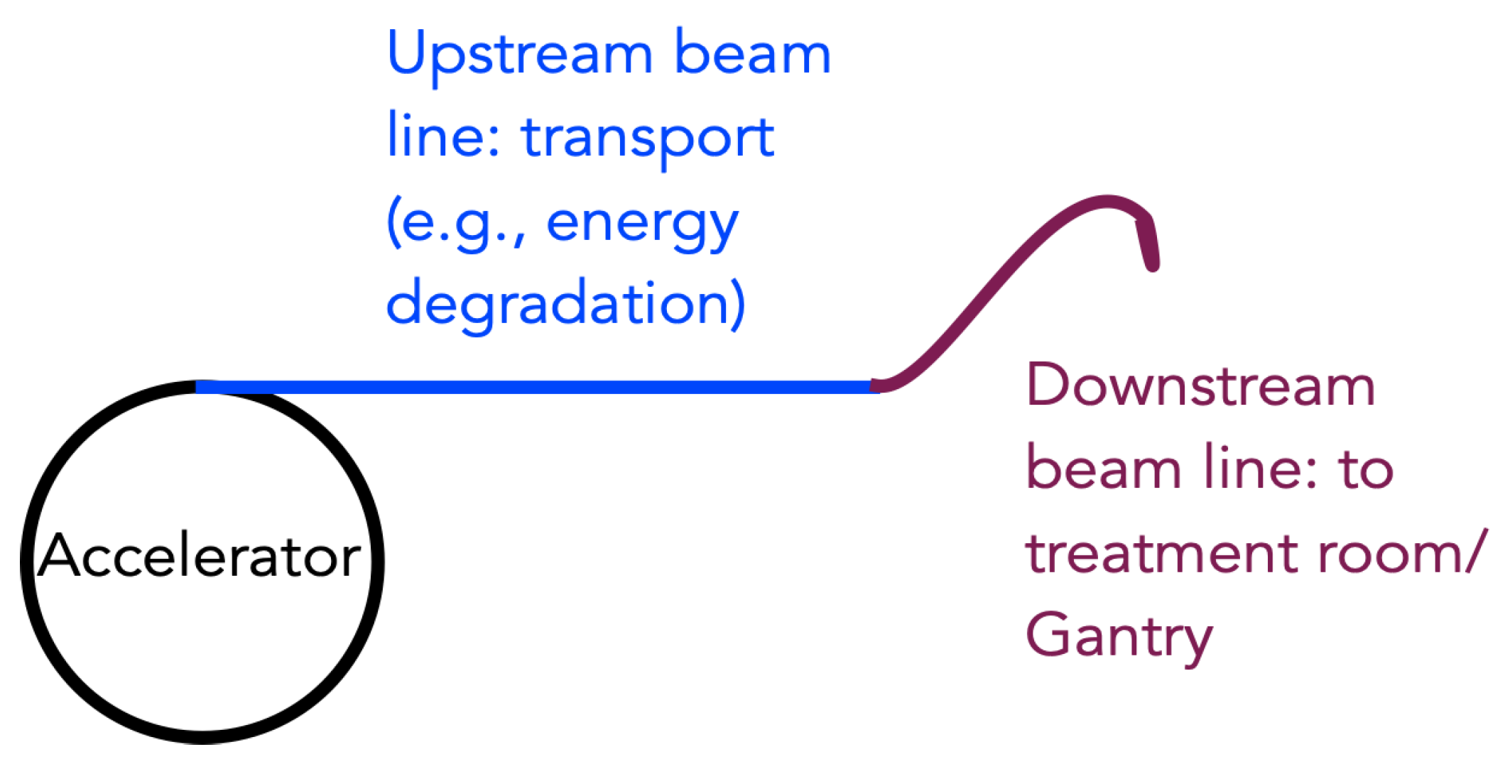
In this paper, we will review some of the challenges faced by proton therapy facilities who want to upgrade to a FLASH irradiation modality. A simplistic sketch of a proton therapy facility is shown in Figure 1. Standard proton therapy is delivered at a dose rate of a few Gy/minute (1–2 Gy/min for standard fractionation schemes and PBS, 10 Gy/min for hypofractionated eye melanoma treatments with scattering). Switching to a FLASH regime means increasing the dose rate by a couple of orders of magnitude. This can be a challenge for the accelerator system itself; reaching high currents at the treatment room is particularly challenging for low energies and cyclotron systems since the energy switching process causes large beam losses and, therefore, limits the current that reaches the treatment room. On the other hand, the short treatment times envisioned for FLASH treatments may also be a challenge for non-continuous-wave accelerators, like synchrotrons; in such systems, the treatment should be delivered within a single spill. The increase of the dose rate poses a challenge also on the dose measurement and monitoring aspects: Most facilities use dose monitoring systems based on ionization chambers, which, however, are expected to suffer from recombination effects at these higher currents; therefore, either reliable correction mechanisms or, eventually, new, dose-rate independent detectors will be required. Controlling a high dose in a very short time also poses much more stringent requirements on the reaction times of the dose control and safety systems. In view of a first clinical application, online dose validation is clearly necessary, as is independent validation of the delivery of the first treatments. We will review all challenges mentioned above, particularly in their relationship to beam diagnostics aspects, in the next sections.
2. Beam Characteristics
This section aims to define the typical characteristics of proton beams used for FLASH irradiation. Together with FLASH irradiation conditions, such as dose delivery time, they determine the requirements that instruments for beam diagnostics must fulfill. The main characteristics discussed in this section are grouped into three categories—beam currents, beam structure, and beam energy.
2.1. Beam Currents
In general, FLASH irradiation implies a relatively high beam intensity. The required currents are at least two orders of magnitude higher than currently used in a clinical setting. It translates to beam currents of the order of 100 to 1000 nA in the treatment area. The same beam intensities or higher will be extracted from an accelerator.
In cyclotron-based facilities, beam monitors upstream of treatment areas are typically suitable for such high currents [14]. Beam coming from a cyclotron has fixed energy; therefore, a degrader is needed. However, this leads to large beam losses; therefore, currents extracted from the cyclotron are high, matching the FLASH range. In the case of synchrotrons, the whole beam diagnostics is usually designed to match beam currents required in the treatment area, as no energy degrader is used and no significant beam losses are present. Therefore, beamline beam monitors are usually optimized for beam current of the order of 1 nA [15]. Detectors based on solutions adequate for low currents, such as ionization chambers or crystal/gas scintillation detectors, will likely experience effects, such as pileup or saturation of signals. These may require either significant modifications or replacement. Some solutions, specifically developed for low currents, can be easily deployed for much higher intensities, as for example, a dielectric-filled reentrant cavity resonator [16]. In addition, beam instrumentation used to monitor proton beams in radioisotope production facilities can potentially find application for FLASH-specific range of beam currents [17,18]. Radioisotope production facilities use beam currents typically well above 100 μA, and beam instrumentation used along their beamlines are capable of monitoring beams as intense as 1 μA or more [19]. However, many of these instruments are slow, so, without specific adaptations, they can be used only for off-line monitoring and beam characterization.
2.2. Beam Structure
Existing proton therapy centers use one of three types of accelerator: an isochronous cyclotron, a synchrocyclotron, or a slow-cycling synchrotron [20]. The beam’s time structure is different for each kind of accelerator, as summarized in Table 1. The main parameters describing the beam’s time structure are acceleration RF frequency, length of a proton bunch, the width of a continuous pulse usable for treatment, and its repetition rate.
In the case of isochronous cyclotrons, the extracted beam can be considered continuous, as RF frequencies of cyclotrons used for proton therapy are in the range of 50–100 MHz. As such, every 10–20 ns, a 1–2 ns long bunch is delivered. The beam continuity, combined with high beam intensities which existing cyclotrons can reach, makes an isochronous cyclotron appear to be the best candidate for potential FLASH proton therapy, unless the dose rate within the pulse is important.
Synchrocyclotrons operate with similar RF frequencies, but the time structure of the extracted beam is significantly different. The RF frequency is decreased synchronously to the increasing revolution time at larger orbit radii. The RF does not vary very quickly; thus, the acceleration is slow and requires many turns up to extraction. The whole cycle is repeated with a frequency of up to 1 kHz. This means that the beam consists of short pulses (order of 1 μs) repeated every 1–3 ms. As such, the use of synchrocyclotrons for FLASH irradiation seems to be challenging and might require some adaptations. For instance, a clinical Mevion HYPERSCAN® (Mevion Medical Systems, Littleton, MA, USA ) system was modified to deliver ultra-high dose rates for FLASH experiments [21]. One of the key changes was an increased pulse width to 20 μs. As such, an average dose rate of up to 200 Gy/s was achieved. However, the pauses between pulses are still long (1.5 ms). As it is still not clear whether the instantaneous dose rate or average dose rate is the main driver of the FLASH protective effect, this unit represents a promising platform for further investigation of this aspect.
Synchrotrons accelerate beam in cycles (spills), each including filling of the ring with bunches of protons, acceleration to a desired energy, extraction, and ramping down to the initial situation [22]. All the existing clinical machines are slow-cycling. This means the extraction is realized in multiple turns, which guarantees a continuous beam for 0.5–5 s with a constant intensity (on average). The treatment pulse for the same energy can be repeated after approximately 2 s. This represents one of several challenges to deploy synchrotrons for FLASH proton therapy [23]. Assuming sufficient intensity, which can be achieved with multi-turn injection, fast energy changes, and rapid extraction are needed. The base for these adaptations would be rapid-cycling synchrotrons. The use of synchrotron for experiments with cells have been recently reported [24]. Ultra-high dose rates up to 800 Gy/s were achieved by applying a high-frequency power dozens of times higher than usual to extract all protons within approximately 50 ms.
The major challenge for online upstream beam monitoring is the total irradiation time. The beam instrumentation must have a suitable time resolution for online beam monitoring. For instance, a sampling rate of acquisition devices must be higher than 1 kHz, as single-fraction irradiation can be as short as 1 ms. For in-room diagnostics, other challenges also have to be taken into account, as discussed in Section 3.
2.3. Beam Energy
There are different scenarios considered for future FLASH treatments. The most straightforward is the so-called ’transmission irradiation’, where the beam ’shoots-through’ the patient at a very high energy. The most challenging but also closest to state of the art treatments instead involves sequential position and energy variation—the so-called ’pencil beam scanning’. The first is easier to realize and allows reaching higher dose rates (because of the lower scattering of high energy beams in tissues) but will generally increase the dose to the normal tissues, which in turn might be clinically unacceptable since the ultra-high dose rates are expected to to spare normal tissue by only about 30–50% [2,25]. Especially for protons, the use of transmission irradiation only is unlikely, as such a solution seems not fully to exploit the sparing properties of protons. Eventually, there are some compromise solutions, such as the use of ridge or pin filters to form a spread-out Bragg peak [23]. Depending on the solution, a different number of energies will be required.
The range of energies used for proton therapy is typically 70–230 MeV. The performance of most diagnostic devices does not depend on energy variation in such a narrow range. The potential energy-dependent response of detectors can usually be corrected by applying a corresponding factor.
Regarding the different machines mentioned before, the only difference is that synchrocyclotron and cyclotron produce beams of fixed energy, unlike the synchrotron. Only the latter does not generally require an energy degrader, as the energy can be varied between cycles. Therefore, the energy spread of the beam is also smaller. Energy change with a degrader typically takes at least 100 ms [26]; thus, sequential energy changes might be too slow for future FLASH treatments. There are concepts of diminishing this time to about 10 ms [27], which is still long for FLASH applications. As previously mentioned, energy degraders also limit beam intensity transported to the treatment area and, thus, the dose rate. A solution, such as the previously mentioned ridge filter, would allow transporting a mono-energetic beam through a beamline. For synchrotrons, rapid cycling with ultrafast energy changes is potentially possible. However, this requires further studies and major developments [23].
3. Control and Monitoring
In the early days of proton therapy, accelerators had a less stable output. The nowadays widely used step-and-shoot PBS delivery technique was invented at Paul Scherrer Institut (PSI) [28] and at GSI Helmholtzzentrum für Schwerionenforschung (GSI) [29] to realize a very precise delivery despite possible beam intensity variations from the particle source [30]. The technique relies on the integration of a certain amount of dose and is as such completely independent of beam current. However, the precision of the detector used for the dose measurement, which triggers the switch from one spot to the next, is of fundamental importance to ensure that FLASH irradiations could be delivered correctly—and safely—in a clinical setting.
Ionization chambers vented to air are commonly used in radiotherapy and are the recommended dosimeter for dosimetry in radiotherapy. As such, they are often integrated in the delivery or monitoring system of proton therapy facilities, with the absolute dose monitoring system relying on them. Therefore, their ability to work at a higher dose rate needs to be assessed before such systems can be released as ’FLASH-ready’ for treatments.
Pencil beam scanning typically employs large dose rates along the beam axis; therefore, studies about dose-rate dependent detector effects have been performed, even before FLASH became an important topic. Liszka et al. [31] found small variation in recombination visible already at clinical dose rates; in particular, they found that recombination corrections estimated at an isochronous-cyclotron facility increase as a function of dose-rate. Such recombination correction variations are usually neglected in clinical practice, either because of their size (less than 0.5% in a clinical volume) or because the variations in dose rates are compensated by the accelerator system by extracting lower currents at higher energies, therefore keeping the dose rate constant at the patient. Beam monitors used for controlling the dose delivery are usually placed close to the patient treatment position, at the end of the beamline and, therefore, will not require dose-rate dependent corrections in this case.
In a first attempt at controlling the delivery in dose-driven mode, Nesteruk et al. [32] have realized a dose-rate dependent efficiency drop correction to the ionization chamber placed at the end of the beamline and used it to control the beam, delivered in PBS spot-scanning mode [30]. The measured efficiency drop of an ionization chamber as a function of beam current was calibrated against the number of protons collected by a Faraday cup, which does not show any dose-rate dependency [33]. In the study, below 5 nA no efficiency drop was visible; the maximum drop observed was below 1% up to 10 nA. for higher currents, though, recombination increases dramatically, causing an efficiency drop up to 20% at the highest current measured. The proposed correction uses as input the current measured more upstream with a dose-rate independent detector; therefore, it could be easily implemented as an online-correction, applied during the delivery. Such a correction strategy could be an easy way to adapt the dosimetry and control systems of already existing clinical proton gantries to FLASH dose-rates, as they usually rely on ionization chambers to decide when to move the beam to the next irradiation position.
Such effects are not unexpected; the Boag theory [34] predicts non-linearity effects depending on the dose per pulse rather than the (average) dose rate, an effect confirmed also in photon and electron studies [35]. Therefore, the beam structure might be very important in realizing a good correction strategy for recombination effects in a proton facility. The challenge in obtaining a high-precision dose monitoring with ionization chambers was highlighted by Darafsheh et al. [21]. In this study, the authors could measure more than 200 Gy/s dose-rate beams produced by a clinical synchro-cyclotron with a commercially available plane-parallel ionization chamber; however, the measured value was about 5% off the expectation, an uncertainty which might be due to several reasons. In particular, the standard dosimetry protocols used to calculate the recombination corrections resulted in correction values that disagreed by up to 4% at the highest dose rates. Common correction approaches show strong limitations when applied in ultra-high dose rates beams.
Other online beam current/dose monitors, developed for high power accelerators, do not show dose-rate dependence and are usually capable of coping with large beam currents. However, the short times associated with the FLASH delivery pose a challenge to the usage of these detectors in a clinical FLASH setting. The secondary emission monitors and ionization chambers in use at the PROSCAN facility at PSI [36] provide reliable current measurements, with limited saturation and recombination effects even at currents of 500 nA; however, the presence of temporary drops in the signal (for about 20 s after beam-on time) and microphonic noise limits their direct applicability in FLASH experiments. In addition, resonator detectors [16] could easily cope with such high currents but usually have a relatively long integration time. To be usable as FLASH monitors, they should provide a reliable signal within only about 100 μs; investigations using these detectors are still ongoing.
Detectors are also linked to important tasks of delivering the treatment safely. With increasing beam current, the time to react to beam delivery instabilities or failures of hardware devices reduces. This makes an active control of the beam delivery rather challenging. Additionally, this time also needs to be estimated very precisely in order to assess how much dose could be erroneously delivered to the patients in case of delivery errors before the safety elements switch off the beam.
If we assume an irradiation scenario of about 10 Gy delivered dose, and 50 Gy/s dose rate, to make sure the additional dose delivered to the patient is 1% or less of the total dose, the reaction time of the safety system must be below 2 ms. For higher dose rates, even shorter reaction times are needed (please note that instantaneous dose rate rather than average dose rate should be considered in these calculations, if the beam structure is not continuous). Such reaction times seem within reach of currently available safety systems; for example, at PSI the first level of safety is able to interrupt the irradiation within 300 μs. However, if higher instantaneous dose rates will be required in future FLASH applications, even faster-reacting systems might be needed. Several aspects could be exploited to improve the reaction times; at the PSI facility cited above, switching from a magnetic deflector to an electrostatic deflector to stop the beam in case of errors reduces the reaction time by a factor 6 [37]. However, since most of the reaction time of the safety system is needed to actually detect the error and communicate the beam-off command, a further reduction of reaction times will also require faster detectors (for example, based on scintillation), as well as fast logic and communication. Therefore, achieving faster monitors will be one of the main steps towards realizing FLASH in the clinic for both dose control and safety.
4. Absolute Dose Measurement
A reliable dose monitoring system is sufficient to deliver the desired dose in a well-known clinical setting, as described in the previous section. As dose delivery in the FLASH mode is still being explored, and accurate dose monitoring in this regime is challenging, an independent measurement of the absolute dose in the experiments and possible first experiences with patients will be necessary to validate the whole dosimetry protocol.
The absolute dose can be measured through active or passive detectors. Active detectors provide real-time dose measurement, while passive ones need to be read out by specific methods and cannot be used to evaluate the delivered dose immediately after irradiation. The standard detector used in a clinical setting is the ionization chamber. As mentioned in Section 3, ionization chambers at ultra-high dose rates suffer from reduced ion collection efficiency, primarily due to volume recombination. Therefore, it is worth exploring other dose-rate-independent possibilities, at least to complement ionization chambers. In this section, examples of both active and passive alternatives, which can be deployed for FLASH irradiation, are given and briefly described.
4.1. Active Detectors
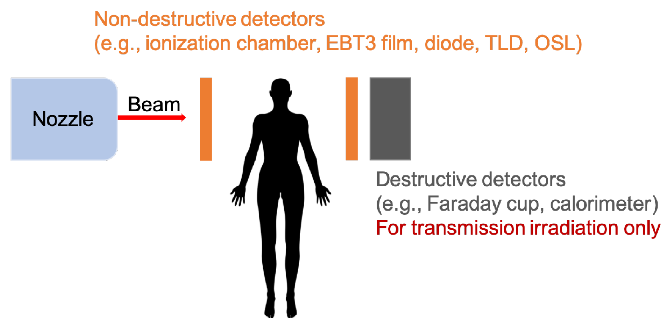
One of the most accurate dosimetry devices is the Faraday cup [33,38]. It allows for an absolute determination of the number of protons reaching its charge collector. Therefore, Faraday cups are widely used to accurately measure low beam currents in different accelerator facilities [39,40], as well as the reference dose of clinical proton beams [38]. The Faraday cup has been shown to give linear response while varying beam current also for ultra-high dose rates [33]. The Faraday cup is a destructive detector and can, thus, be used only as a beam stopper (Figure 2). Therefore, it can only be employed in transmission mode.
While thinking about high dose rates, a natural concept is to apply solutions widely used in high energy physics. One of the easily applicable detectors would be calorimeters. A calorimeter measures the energy deposited by particles contained in a particle shower initiated by the incident particle in the material of the calorimeter. Compact graphite calorimeters have already been developed for dosimetry of clinical proton beams [41,42]. As in the case of the Faraday cup, this kind of dosimeter cannot be applied in front of the patient (Figure 2).
Semiconductor-based dosimeters, such as a silicon diode or diamond, represent another class of active detectors. Standard silicon diodes will suffer from readout saturation when exposed to ultra-high dose rates. Some efforts have been made to overcome that problem, including the development of new p-type silicon strip detectors (SSD) [43]. They have found application in dosimetry of X-ray microbeams and have been tested at ultra-high dose rates [44,45,46]. Diamond detectors represent an attractive choice for dosimetry. Diamond has numerous advantages, among which are a good tissue equivalency (its atomic number is very close to the effective atomic number of the tissue), a high resistance to radiation damage, high sensitivity and stability of response, and a good time resolution [47]. Diamond detectors can be produced in small sizes (compared to standard dosimeters, such as cylindrical or plane-parallel ionization chambers), so they can be easily placed in different experimental setups and anatomical structures of irradiated phantoms, as well as be deployed for in vivo dosimetery [48]. Diamond detectors have already been used in dosimetry of proton pencil beams [49]. They have also been employed in FLASH experiments, and no significant dose-rate dependency has been found for dose rates up to 40 Gy/s [9].
4.2. Passive Detectors
One of the most commonly used passive detectors for clinical beams is radiochromic films. These are self-developing radiation dosimeters. The film contains an active layer with a dye that changes color when exposed to ionizing radiation. The intensity of the colorization is proportional to the dose. In particular, Gafchromic® EBT3 films (Ashland ISP Advanced Materials, Kearny, NJ, USA) are used for dosimetry with the clinical photon, electron, and proton beams [50]. In several studies, it has been shown that the response of Gafchromic films should be independent of the dose rate [11]. EBT3 films have already been employed in FLASH studies with protons, e.g., Reference [51].
Alanine is an amino acid that forms a very stable free radical when exposed to ionizing radiation. Irradiated dosimeters are read out by means of Electron Spin Resonance (ESR), and the signal produced by the free radical is proportional to the dose. This kind of dosimeter has been used for dose verification in the first FLASH treatment of a human with electrons [12]. Although alanine detectors have been shown to be dose-rate dependent, it was not significant for delivered doses below 5000 Gy [52].
Thermoluminescent dosimeter (TLD) is another variety of passive dosimeters. It contains a thermoluminescent crystalline material, which absorbs and traps some of the energy when exposed to ionizing radiation. Some of the excited electrons which reach the conduction band do not recombine to the valence state but are trapped instead in intermediate energy levels by existing material defects or added impurities. For reading out, the detector has to be heated so that the trapped electrons reach the conduction band and recombine to the ground state emitting photons of visible light. The intensity of the light is related to the dose to which the crystal was exposed. TLDs have been shown to keep the dose-rate independence also for ultra-high dose rates while exposed to electrons and photons [53,54,55]. The use of TLDs in FLASH experiments with electron beams has been reported [55,56].
Optically-stimulated luminescence dosimeters (OSLDs) are very similar to TLDs. The major difference is that OSL dosimeters only require optical stimulation, instead of heat, to bring electrons to the conduction band and make them recombine with the holes in the valence band. Therefore, a different readout technique is used. These detectors can be cut to the desired size and are, thus, easy to accommodate in any experiment. OSL detectors of various sizes have been tested with protons at ultra-high dose rates up to 9000 Gy/s, and no dose-rate dependency was found [57].
5. Conclusions
We have quickly summarized some of the challenges and proposed solutions for beam diagnostics and monitoring of proton FLASH experiments. These experiments may represent a revolution in the way the dose is delivered to a patient, going from treatments taking weeks and a low dose per session, to treatments of high-dose administered in one or few sessions.
Since most of the evidence seems to show that short treatment time and high doses are in general needed to trigger a reproducible FLASH effect, we hypothesized what such scenarios could look like in a modern clinical facility. State-of-the-art proton facilities, based on cyclotrons and synchro-cyclotrons, have already shown their ability to reach FLASH dose rates in several experiments, and first proof-of-principle experiments in synchrotrons have also been successful. Beam current monitoring at these facilities is often able to cope with large beam currents, even though the commonly used dose control systems based on ionization chambers will require either dose-rate-dependent corrections to recombination effect or new, dose-rate-independent detectors. A big challenge for monitoring and safety will be the very short irradiation times, which will require the diagnostics to work at much higher sampling rates. For first experiments and patients, an external validation of the absolute delivered dose will likely be required, where we also illustrated the different possibilities.
The potential of FLASH therapy is still being explored, and current proton therapy machines are generally able to provide FLASH beams and a reasonably precise diagnostics system. The ’first in human’ FLASH trial (FAST-01 [13]) has already started recruiting patients. Indeed, proton therapy seems to be the radiation therapy platform with the fastest pathway to the application of FLASH irradiation to a large variety of tumors. On the other hand, the exact beam parameters needed to trigger the FLASH effect are still being investigated [10]. Biological experiments have so far investigated only a handful of tissues and tumor models, and different tissues/organs might show different dose and/or dose-rate thresholds. New findings might lead to even more stringent requirements in terms of dose linearity, dose precision, and diagnostics speed, for example. Therefore, we expect still a few years of development will be needed before patients can reliably be treated with this technique.
Author Contributions
Both authors contributed equally to the concept, literature research, writing and editing of the manuscript. Both authors have read and agreed to the published version of the manuscript.
Funding
The APC was funded by the Lib4RI Open-Access Fund.
Institutional Review Board Statement
Not applicable.
Informed Consent Statement
Not applicable.
Data Availability Statement
Not applicable.
Acknowledgments
We would like to thank David Meer and Tony Lomax from the Center for Proton Therapy, PSI, for reviewing the manuscript.
Conflicts of Interest
The authors declare no conflict of interest.
References
- Foote, R.L.; Stafford, S.L.; Petersen, I.A.; Pulido, J.S.; Clarke, M.J.; Schild, S.E.; Garces, Y.I.; Olivier, K.R.; Miller, R.C.; Haddock, M.G.; et al. The clinical case for proton beam therapy. Radiat. Oncol. 2012, 7, 174. [Google Scholar] [CrossRef] [PubMed] [Green Version]
- Vozenin, M.C.; Hendry, J.; Limoli, C. Biological Benefits of Ultra-high Dose Rate FLASH Radiotherapy: Sleeping Beauty Awoken. Clin. Oncol. 2019, 31, 407–415. [Google Scholar] [CrossRef]
- Wilson, P.; Jones, B.; Yokoi, T.; Hill, M.; Vojnovic, B. Revisiting the ultra-high dose rate effect: Implications for charged particle radiotherapy using protons and light ions. Br. J. Radiol. 2012, 85, e933. [Google Scholar] [CrossRef] [Green Version]
- Favaudon, V.; Caplier, L.; Monceau, V.; Pouzoulet, F.; Sayarath, M.; Fouillade, C.; Poupon, M.F.; Brito, I.; Hupé, P.; Bourhis, J.; et al. Ultrahigh dose-rate FLASH irradiation increases the differential response between normal and tumor tissue in mice. Sci. Transl. Med. 2014, 6, 245ra93–245ra93. [Google Scholar] [CrossRef] [PubMed]
- Montay-Gruel, P.; Petersson, K.; Jaccard, M.; Boivin, G.; Germond, J.F.; Petit, B.; Doenlen, R.; Favaudon, V.; Bochud, F.; Bailat, C.; et al. Irradiation in a flash: Unique sparing of memory in mice after whole brain irradiation with dose rates above 100 Gy/s. Radiother. Oncol. 2017, 124, 365–369. [Google Scholar] [CrossRef]
- Citrin, D.E.; Mitchell, J.B. Mechanisms of Normal Tissue Injury From Irradiation. Semin. Radiat. Oncol. 2017, 27, 316–324. [Google Scholar] [CrossRef]
- Schüler, E.; Trovati, S.; King, G.; Lartey, F.; Rafat, M.; Villegas, M.; Praxel, A.J.; Loo, B.W.; Maxim, P.G. Experimental Platform for Ultra-high Dose Rate FLASH Irradiation of Small Animals Using a Clinical Linear Accelerator. Int. J. Radiat. Oncol. Biol. Phys. 2017, 97, 195–203. [Google Scholar] [CrossRef]
- Lempart, M.; Blad, B.; Adrian, G.; Bäck, S.; Knöös, T.; Ceberg, C.; Petersson, K. Modifying a clinical linear accelerator for delivery of ultra-high dose rate irradiation. Radiother. Oncol. 2019, 139, 40–45. [Google Scholar] [CrossRef]
- Patriarca, A.; Fouillade, C.; Auger, M.; Martin, F.; Pouzoulet, F.; Nauraye, C.; Heinrich, S.; Favaudon, V.; Meyroneinc, S.; Dendale, R.; et al. Experimental Set-up for FLASH Proton Irradiation of Small Animals Using a Clinical System. Int. J. Radiat. Oncol. Biol. Phys. 2018, 102, 619–626. [Google Scholar] [CrossRef] [PubMed]
- Bourhis, J.; Montay-Gruel, P.; Gonçalves Jorge, P.; Bailat, C.; Petit, B.; Ollivier, J.; Jeanneret-Sozzi, W.; Ozsahin, M.; Bochud, F.; Moeckli, R.; et al. Clinical translation of FLASH radiotherapy: Why and how? Radiother. Oncol. 2019, 139, 11–17. [Google Scholar] [CrossRef] [PubMed]
- Esplen, N.M.; Mendonca, M.S.; Bazalova-Carter, M. Physics and biology of ultrahigh dose-rate (FLASH) radiotherapy: A topical review. Phys. Med. Biol. 2020, 65, 23TR03. [Google Scholar] [CrossRef]
- Bourhis, J.; Sozzi, W.J.; Jorge, P.G.; Gaide, O.; Bailat, C.; Duclos, F.; Patin, D.; Ozsahin, M.; Bochud, F.; Germond, J.F.; et al. Treatment of a first patient with FLASH-radiotherapy. Radiother. Oncol. 2019, 139, 18–22. [Google Scholar] [CrossRef]
- ClinicalTrials.gov [Internet]. Identifier NCT04592887, Feasibility Study of FLASH Radiotherapy for the Treatment of Symptomatic Bone Metastases (FAST-01); National Library of Medicine (US): Bethesda, MD, USA, 2020. Available online: clinicaltrials.gov/ct2/show/NCT04592887 (accessed on 15 January 2021).
- Dölling, R.; Lin, S.; Duperrex, P.; Gamma, G.; Keil, B. Beam diagnostics for the proton therapy facility PROSCAN. In Proceedings of the 8th International Topical Meeting on Nuclear Applications and Utilization of Accelerators, ACCAPP’07, Pocatello, ID, USA, 29 July–2 August 2007. [Google Scholar]
- Coutrakon, G.; Miller, D.; Kross, B.J.; Anderson, D.F.; DeLuca, P., Jr.; Siebers, J. A beam intensity monitor for the Loma Linda cancer therapy proton accelerator. Med. Phys. 1991, 18, 817–820. [Google Scholar] [CrossRef]
- Srinivasan, S.; Duperrex, P.A.; Schippers, J.M. Beamline characterization of a dielectric-filled reentrant cavity resonator as beam current monitor for a medical cyclotron facility. Phys. Med. 2020, 78, 101–108. [Google Scholar] [CrossRef]
- Auger, M.; Braccini, S.; Carzaniga, T.; Ereditato, A.; Nesteruk, K.; Scampoli, P. A detector based on silica fibers for ion beam monitoring in a wide current range. J. Instrum. 2016, 11, P03027. [Google Scholar] [CrossRef]
- Nesteruk, K.; Auger, M.; Braccini, S.; Carzaniga, T.; Ereditato, A.; Scampoli, P. A system for online beam emittance measurements and proton beam characterization. J. Instrum. 2018, 13, P01011. [Google Scholar] [CrossRef] [Green Version]
- Braccini, S. Compact Medical Cyclotrons and their use for Radioisotope Production and Multi-disciplinary Research. In Proceedings of the International Conference on Cyclotrons and Their Applications (Cyclotrons’16), Zurich, Switzerland, 11–16 September 2016; Number 21 in International Conference on Cyclotrons and Their Applications. JACoW: Geneva, Switzerland, 2017; pp. 229–234. [Google Scholar] [CrossRef]
- Farr, J.B.; Flanz, J.B.; Gerbershagen, A.; Moyers, M.F. New horizons in particle therapy systems. In Medical Physics; John Wiley and Sons Ltd.: Hoboken, NJ, USA, 2018; Volume 45, pp. e953–e983. [Google Scholar] [CrossRef] [Green Version]
- Darafsheh, A.; Hao, Y.; Zwart, T.; Wagner, M.; Catanzano, D.; Williamson, J.F.; Knutson, N.; Sun, B.; Mutic, S.; Zhao, T. Feasibility of proton FLASH irradiation using a synchrocyclotron for preclinical studies. Med. Phys. 2020, 47, 4348–4355. [Google Scholar] [CrossRef] [PubMed]
- Schippers, J.M. Chapter 3: Proton Accelerators. In Proton Therapy Physics; Paganetti, H., Ed.; CRC Press: Boca Raton, FL, USA, 2019. [Google Scholar]
- Jolly, S.; Owen, H.; Schippers, M.; Welsch, C. Technical challenges for FLASH proton therapy. Phys. Med. 2020, 78, 71–82. [Google Scholar] [CrossRef]
- Iwata, H.; Toshito, T.; Omachi, C.; Umezawa, M.; Shinozawa, Y.; Yamada, M.; Nakajima, K.; Nomura, K.; Ogino, H.; Shibamoto, Y. Scanning Proton FLASH Irradiation Using a Synchrotron Accelerator: Effects on Cultured Cells and Differences by Irradiation Positions. Int. J. Radiat. Oncol. Biol. Phys. 2020, 108, e522. [Google Scholar] [CrossRef]
- Diffenderfer, E.S.; Verginadis, I.I.; Kim, M.M.; Shoniyozov, K.; Velalopoulou, A.; Goia, D.; Putt, M.; Hagan, S.; Avery, S.; Teo, K.; et al. Design, Implementation, and in Vivo Validation of a Novel Proton FLASH Radiation Therapy System. Int. J. Radiat. Oncol. Biol. Phys. 2020, 106, 440–448. [Google Scholar] [CrossRef] [Green Version]
- Psoroulas, S.; Bula, C.; Actis, O.; Weber, D.C.; Meer, D. A predictive algorithm for spot position corrections after fast energy switching in proton pencil beam scanning. Med. Phys. 2018, 45, 4806–4815. [Google Scholar] [CrossRef] [PubMed]
- Nesteruk, K.P.; Calzolaio, C.; Meer, D.; Rizzoglio, V.; Seidel, M.; Schippers, J.M. Large energy acceptance gantry for proton therapy utilizing superconducting technology. Phys. Med. Biol. 2019, 64, 175007. [Google Scholar] [CrossRef] [PubMed] [Green Version]
- Pedroni, E.; Bacher, R.; Blattmann, H.; Böhringer, T.; Coray, A.; Lomax, A.; Lin, S.; Munkel, G.; Scheib, S.; Schneider, U. The 200-MeV proton therapy project at the Paul Scherrer Institute: conceptual design and practical realization. Med. Phys. 1995, 22, 37–53. [Google Scholar] [CrossRef] [PubMed]
- Haberer, T.; Becher, W.; Schardt, D.; Kraft, G. Magnetic scanning system for heavy ion therapy. Nucl. Inst. Methods Phys. Res. A 1993, 330, 296–305. [Google Scholar] [CrossRef]
- Lin, S.; Boehringer, T.; Coray, A.; Grossmann, M.; Pedroni, E. More than 10 years experience of beam monitoring with the Gantry 1 spot scanning proton therapy facility at PSI. Med. Phys. 2009, 36, 5331. [Google Scholar] [CrossRef]
- Liszka, M.; Stolarczyk, L.; Kłodowska, M.; Kozera, A.; Krzempek, D.; Mojżeszek, N.; Pędracka, A.; Waligórski, M.P.R.; Olko, P. Ion recombination and polarity correction factors for a plane–parallel ionization chamber in a proton scanning beam. Med. Phys. 2018, 45, 391–401. [Google Scholar] [CrossRef] [Green Version]
- Nesteruk, K.P.; Togno, M.; Grossmann, M.; Lomax, A.J.; Weber, D.C.; Schippers, J.M.; Safai, S.; Meer, D.; Psoroulas, S. Commissioning of a clinical pencil beam scanning proton therapy unit for ultrahigh dose rates (FLASH). arXiv 2021, arXiv:2101.01770. [Google Scholar]
- Winterhalter, C.; Togno, M.; Nesteruk, K.P.; Emert, F.; Psoroulas, S.; Vidal, M.; Meer, D.; Weber, D.C.; Lomax, A.; Safai, S. Faraday cup for commissioning and quality assurance for proton pencil beam scanning beams at conventional and ultra-high dose rates. Phys. Med. Biol. 2020. Submitted. [Google Scholar]
- Boag, J.W.; Hochhäuser, E.; Balk, O.A. The effect of free-electron collection on the recombination correction to ionization measurements of pulsed radiation. Phys. Med. Biol. 1996, 41, 885–897. [Google Scholar] [CrossRef]
- Bruggmoser, G.; Saum, R.; Schmachtenberg, A.; Schmid, F.; Schüle, E. Determination of the recombination correction factorkSfor some specific plane-parallel and cylindrical ionization chambers in pulsed photon and electron beams. Phys. Med. Biol. 2006, 52, N35–N50. [Google Scholar] [CrossRef]
- Dölling, R. Ionisation Chambers and Secondary Emission Monitors at the PROSCAN Beam Lines. AIP Conf. Proc. 2006, 868, 271–280. [Google Scholar] [CrossRef]
- Schippers, M.; Duppich, J.; Goitein, G.; Hug, E.; Jermann, M.; Mezger, A. First Year of Operation of Psi’s New Sc Cyclotron and Beam Lines for Proton Therapy. Proc. Cyclotrons 2007, 2007, 15–17. [Google Scholar]
- Gomà, C.; Lorentini, S.; Meer, D.; Safai, S. Proton beam monitor chamber calibration. Phys. Med. Biol. 2014, 59, 4961–4971. [Google Scholar] [CrossRef] [PubMed]
- Harasimowicz, J.; Welsch, C.P. Faraday cup for low-energy, low-intensity beam measurements at the USR. In Proceedings of the 2010 Beam Instrumentation Workshop, BIW 2010, Newport News, VA, USA, 15–19 April 2010; pp. 257–259. [Google Scholar]
- Auger, M.; Braccini, S.; Ereditato, A.; Nesteruk, K.P.; Scampoli, P. Low current performance of the Bern medical cyclotron down to the pA range. Meas. Sci. Technol. 2015, 26, 94006. [Google Scholar] [CrossRef]
- Palmans, H.; Thomas, R.; Simon, M.; Duane, S.; Kacperek, A.; DuSautoy, A.; Verhaegen, F. A small-body portable graphite calorimeter for dosimetry in low-energy clinical proton beams. Phys. Med. Biol. 2004, 49, 3737–3749. [Google Scholar] [CrossRef]
- Christensen, J.B.; Vestergaard, A.; Andersen, C.E. Using a small-core graphite calorimeter for dosimetry and scintillator quenching corrections in a therapeutic proton beam. Phys. Med. Biol. 2020, 65, 215023. [Google Scholar] [CrossRef] [PubMed]
- Rosenfeld, A.B. Electronic dosimetry in radiation therapy. Radiat. Meas. 2006, 41, S134–S153. [Google Scholar] [CrossRef]
- Petasecca, M.; Cullen, A.; Fuduli, I.; Espinoza, A.; Porumb, C.; Stanton, C.; Aldosari, A.H.; Bräuer-Krisch, E.; Requardt, H.; Bravin, A.; et al. X-tream: A novel dosimetry system for synchrotron microbeam radiation therapy. J. Instrum. 2012, 7, P07022. [Google Scholar] [CrossRef] [Green Version]
- Fournier, P.; Cornelius, I.; Dipuglia, A.; Cameron, M.; Davis, J.A.; Cullen, A.; Petasecca, M.; Rosenfeld, A.B.; Bräuer-Krisch, E.; Häusermann, D.; et al. X-Tream dosimetry of highly brilliant X-ray microbeams in the MRT hutch of the Australian Synchrotron. Radiat. Meas. 2017, 106, 405–411. [Google Scholar] [CrossRef] [Green Version]
- Davis, J.A.; Paino, J.R.; Dipuglia, A.; Cameron, M.; Siegele, R.; Pastuovic, Z.; Petasecca, M.; Perevertaylo, V.L.; Rosenfeld, A.B.; Lerch, M.L. Characterisation and evaluation of a PNP strip detector for synchrotron microbeam radiation therapy. Biomed. Phys. Eng. Express 2018, 4, 044002. [Google Scholar] [CrossRef] [Green Version]
- Cirrone, G.; Cuttone, G.; Lo Nigro, S.; Mongelli, V.; Raffaele, L.; Sabini, M.; Valastro, L.; Bucciolini, M.; Onori, S. Dosimetric characterization of CVD diamonds irradiated with 62MeV proton beams. In Nuclear Instruments and Methods in Physics Research Section A: Accelerators, Spectrometers, Detectors and Associated Equipment, Proceedings of the 5th International Conference on Radiation Effects on Semiconductor Materials Detectors and Devices, Florence, Italy, 10–13 October 2004; Elsevier: Amsterdam, The Netherlands, 2005; Volume 552, pp. 197–202. [Google Scholar] [CrossRef]
- Dieterich, S.; Ford, E.; Pavord, D.; Zeng, J. Chapter 3—In-Vivo Dosimetry. In Practical Radiation Oncology Physics; Dieterich, S., Ford, E., Pavord, D., Zeng, J., Eds.; Elsevier: Philadelphia, PA, USA, 2016; pp. 30–39. [Google Scholar] [CrossRef]
- Gomà, C.; Marinelli, M.; Safai, S.; Verona-Rinati, G.; WÃŒrfel, J. The role of a microDiamond detector in the dosimetry of proton pencil beams. Z. Fuer Med. Phys. 2016, 26, 88–94. [Google Scholar] [CrossRef]
- Sorriaux, J.; Kacperek, A.; Rossomme, S.; Lee, J.; Bertrand, D.; Vynckier, S.; Sterpin, E. Evaluation of Gafchromic EBT3 films characteristics in therapy photon, electron and proton beams. Phys. Med. 2013, 29, 599–606. [Google Scholar] [CrossRef] [PubMed] [Green Version]
- Buonanno, M.; Grilj, V.; Brenner, D.J. Biological effects in normal cells exposed to FLASH dose rate protons. Radiother. Oncol. 2019, 139, 51–55. [Google Scholar] [CrossRef] [PubMed]
- Desrosiers, M.F.; Puhl, J.M.; Cooper, S.L. An absorbed-dose/dose-rate dependence for the alanine-EPR dosimetry system and its implications in high-dose ionizing radiation metrology. J. Res. Natl. Inst. Stand. Technol. 2008, 113, 79–95. [Google Scholar] [CrossRef] [PubMed]
- Tochilin, E.; Goldstein, N. Dose rate and spectral measurements from pulsed x-ray generators. Health Phys. 1966, 12, 1705–1714. [Google Scholar] [CrossRef]
- Karsch, L.; Beyreuther, E.; Burris-Mog, T.; Kraft, S.; Richter, C.; Zeil, K.; Pawelke, J. Dose rate dependence for different dosimeters and detectors: TLD, OSL, EBT films, and diamond detectors. Med. Phys. 2012, 39, 2447–2455. [Google Scholar] [CrossRef] [PubMed]
- Jorge, P.G.; Jaccard, M.; Petersson, K.; Gondré, M.; Durán, M.T.; Desorgher, L.; Germond, J.F.; Liger, P.; Vozenin, M.C.; Bourhis, J.; et al. Dosimetric and preparation procedures for irradiating biological models with pulsed electron beam at ultra-high dose-rate. Radiother. Oncol. 2019, 139, 34–39. [Google Scholar] [CrossRef]
- Jaccard, M.; Petersson, K.; Buchillier, T.; Germond, J.F.; Durán, M.T.; Vozenin, M.C.; Bouhris, J.; Bochud, F.O.; Bailat, C. High dose-per-pulse electron beam dosimetry: usability and dose-rate independence of EBT3 Gafchromic films. Med. Phys. 2017, 44, 725–735. [Google Scholar] [CrossRef]
- Christensen, J.B.; Togno, M.; Nesteruk, K.P.; Psoroulas, S.; Meer, D.; Weber, D.C.; Lomax, T.; Yukihara, E.G.; Safai, S. Al2O3:C optically stimulated luminescence dosimeters (OSLDs) for ultra-high dose-rate proton dosimetry. Phys. Med. Biol. 2021, in press. [Google Scholar] [CrossRef]
Figure 1.
Schematic picture of a proton therapy facility. We identify here the ’upstream’ and ’downstream’ beamlines that we will refer to in the text.
Figure 1.
Schematic picture of a proton therapy facility. We identify here the ’upstream’ and ’downstream’ beamlines that we will refer to in the text.

Figure 2.
Destructive and non-destructive detectors for dosimetry. The former may be used on either side of the patient, while the latter can serve beam stopper only in the case of transmission irradiation.
Figure 2.
Destructive and non-destructive detectors for dosimetry. The former may be used on either side of the patient, while the latter can serve beam stopper only in the case of transmission irradiation.


Table 1.
Typical beam time structure for different clinical accelerators.
| Accelerator Type | Isochronous Cyclotron | Synchrocyclotron | Synchrotron |
|---|---|---|---|
| RF Frequency (MHz) | 50–100 | 50–100 | 1–10 |
| Bunch Length (ns) | 1–2 | 1–2 | 25–200 |
| Treatment Pulse Width (s) | - | (1–20) | 0.5–5 |
| Pulse Repetition Rate (Hz) | continuous | ∼ | 0.5 |
Publisher’s Note: MDPI stays neutral with regard to jurisdictional claims in published maps and institutional affiliations. |
© 2021 by the authors. Licensee MDPI, Basel, Switzerland. This article is an open access article distributed under the terms and conditions of the Creative Commons Attribution (CC BY) license (http://creativecommons.org/licenses/by/4.0/).
Share and Cite
MDPI and ACS Style
Nesteruk, K.P.; Psoroulas, S. FLASH Irradiation with Proton Beams: Beam Characteristics and Their Implications for Beam Diagnostics. Appl. Sci. 2021, 11, 2170. https://doi.org/10.3390/app11052170
AMA Style
Nesteruk KP, Psoroulas S. FLASH Irradiation with Proton Beams: Beam Characteristics and Their Implications for Beam Diagnostics. Applied Sciences. 2021; 11(5):2170. https://doi.org/10.3390/app11052170
Chicago/Turabian StyleNesteruk, Konrad P., and Serena Psoroulas. 2021. "FLASH Irradiation with Proton Beams: Beam Characteristics and Their Implications for Beam Diagnostics" Applied Sciences 11, no. 5: 2170. https://doi.org/10.3390/app11052170
Note that from the first issue of 2016, this journal uses article numbers instead of page numbers. See further details here.