
Study on Influence of Multi-Parameter Variation of Bladed Disk System on Vibration Characteristics


1
School of Energy and Power, Shenyang Institute of Engineering, Shenyang 110136, China
2
School of Science, Northeastern University, Shenyang 110819, China
*
Author to whom correspondence should be addressed.
Appl. Sci. 2021, 11(7), 3084; https://doi.org/10.3390/app11073084
Submission received: 11 March 2021
/
Revised: 18 March 2021
/
Accepted: 18 March 2021
/
Published: 30 March 2021
(This article belongs to the Special Issue Bladed Disks Structural Dynamics)
Abstract
:As the main components of the rotor system of aero-engines and other rotating machinery equipment, the bladed disk system has high requirements on its structure design, safety and stability. Taking the rotor disk system of aero-engines as the research object, modal calculation of the rotor disk system was based on the group theory algorithm, and using the fine sand movement on the experimental disk to express the disk vibration shape. The experimental vibration mode is used to compare with the finite element calculation results to verify the reliability of the finite element analysis. Study on the effect of dissonance parameter changes on the bladed disk system vibration characteristics concluded that the vibration mode trends of the blisk system and the disc are, basically, consistent. As the mass of the blade increases, the modal frequencies of the entire blisk system gradually decrease, and the amplitude slightly increases. When the mass increases at different parts of the blade, the effect on the modal frequencies of the bladed disk system are not obvious. When the bladed disk system vibrates at low frequency, the disc will not vibrate and each blade will vibrate irregularly. The bladed disk should be avoided to work in this working area for a long time, so as not to cause fatigue damage or even fracture of some blades.
1. Introduction
As the main components of the rotor system of aero-engines and other rotating machinery equipment, the bladed disk system has high requirements on its structure design and safety stability. Under the harsh conditions of high rotating speed, high temperature and high pressure, the bladed disk system is likely to scale and change in mass, causing blade damage and shedding due to high loading and centrifugal force. The change of blade mass and blade detachment will seriously affect the balance of the rotor system. The imbalance of the rotor system will cause serious accidents.
In recent years, scholars have carried out theoretical, numerical simulation and experimental study on vibration and dynamic characteristics of the dissonant bladed disk system. Petrov et al. [1,2] discussed on the numerical simulation analysis of dissonant bladed disk and obtained the results of localized modal analysis of a dissonant bladed disk. By comparing the experimental results, the results of modal analysis were very consistent with the experimental results. Castanier et al. [3] summarized various modeling principles based on finite element and methods for the disc-dissonance recognition, sensitivity analysis and forced response prediction. Bladh et al. [4] studied the forced response characteristics of the dissonant bladed disk using the reduced finite element model and found that the forced response of the bladed disk system with localized vibration mode would not necessarily increase significantly but might also decrease. From the statistical average, the forced response will increase, and the peak will appear with the increase of random dissonance. Wang [5] studied the modal and forced vibration response of the dissonant bladed disk and projected it into the modal space of the harmonic bladed disk system. The results show that the proposed scheme can accurately describe the effect of dissonance on the structure vibration characteristics of the bladed disk system. Wang [6] studied the localization problem of the inherent vibration of the bladed disk system by using the modeling method of centralized parameters on the bladed disk. The results show that the disk system is sensitive to random dissonance. Liao et al. [7,8,9,10] used the system modeling method of centralized parameters to obtain the maximum differential mode and maximum amplitude magnification coefficient of the blade stiffness dissonance of the corresponding coordinated system, indicating the local phenomenon of the system dissonance jump. In addition, based on the intelligent optimization method, the worst state mode localization method of dissonant disk structure is proposed. Zhao et al. [11] studied the rubbing of the mistuned bladed disk system with variable thickness blades, an elastically supported shaft-variable thickness blade-coupled finite element model was established. Yu [12,13,14] established the finite element simulation model of the impeller, introduced the influence factors of wrong frequency, and analyzed the mode and probability response localization characteristics of the bladed disk system. The results show that the fault frequency can cause significant localization of vibration, and with the increase of dissonance, there will be a peak in the level of dynamic response and the degree of dispersion of the dissonant system. Xu [15] studied the localization and periodic loss of system vibration caused by structural failure by establishing different models of the discordant bladed disk system. Box et al. [16] considered using active dissonance to reduce the sensitivity of the disc to random dissonance and chose a genetic algorithm to optimize the arrangement of two kinds of active dissonance blades A and B. Calleja and Lamikiz et al. [17,18] presented a methodology for complex surface machining based on cutting forces prediction and described the implementation of a cutting force prediction model. Rahimi [19] first used a genetic algorithm to obtain the worst dissonance arrangement, and then replaced part of the blade by active dissonance to reduce the overall vibration level of the disc system. Vargiu et al. [20] divided the whole bladed disk system into several sectors, first optimizing the internal leaves of the sector, and then prioritizing each sector as a whole. Zhao et al. [21,22,23] shed important light on the design of a novel graphene-reinforced blade-shaft system for remarkably improved dynamic performance. Choi et al. [24] first randomly sorted A and B leaves, calculated the maximum and minimum amplitudes under fixed excitation, and then estimated the bladed amplification factor and sensitivity coefficient, and then sequenced them by using genetic algorithm according to these two coefficients. Choi et al. [25] also used a variety of heuristic algorithms to sort dissonant leaves. Suárez [26,27] researched the effects of high-pressure cooling on the wear patterns on turning inserts used on alloy IN718. Scarselli [28] used a genetic algorithm to obtain the optimal solution of 21 bladed disk systems. Yang et al. [29] and Chen et al. [30] optimized the blade arrangement from the perspective of static balancing. Zhao [31] simplified the problem of dissonant blade sequencing by reducing multiple constraint conditions to single constraint conditions. Yue et al. [32] studied the problem of bladed sequencing by using a stepwise optimization method that optimizes multiple constraints one by one. Zhao et al. [33,34,35] investigated free vibration behaviors of a functionally graded (FG) disk-shaft rotor system, which was reinforced with graphene nanoplatelets (GPL) resting on elastic supports. Yuan et al. [36,37] studied the optimization arrangement of vibration damping of dissonant bladed disk system by establishing a centralized parameter model. According to different intelligent optimization algorithms, a new optimization arrangement method was proposed. The study shows that different blade installation sequence will greatly affect the inherent characteristics of the bladed disk system. Proper blade arrangement can effectively reduce the amplitude of forced vibration of the bladed disk system and reduce the localization degree of system vibration.
In this paper, the modal of the bladed disk system is calculated and analyzed based on the group theory, the frequency modulation excitation is applied to the simulated disk by using the principle of resonance method, and the simulated disk vibration mode is represented by fine sand on the disk, and the experimental vibration mode is compared with the finite element calculation results to verify the reliability of the finite element analysis. Ten working conditions of the bladed disk system with different parameters are designed, and the effects of detuning parameters on the vibration characteristics of the structure of the bladed disk system are discussed and analyzed.
2. Modal Calculation of Bladed Disk System System Based on Group Theory
The group theory is one of the main methods for vibration analysis of circularly symmetric structures. If N blades are identical, that is, the same geometrical, material and natural vibration frequency, then the bladed disk system is an N-order circularly symmetric structure. From the perspective of group theory, the N-order cyclic symmetric structure is about the symmetry of CN groups, so the N-order cyclic symmetric structure is also known as the CN structure. The vibration of the bladed disk system is analyzed by using group theory and modal synthesis. By using the property of block circulation matrix , the motion equation of the whole system is reduced to a complex characteristic equation of a lower order and transformed into a real characteristic equation. Then the software of real symmetric matrix eigenvalue is used to solve the problem.
It can be inferred from the properties of the cyclic symmetry structure that the node displacements in adjacent sectors of a cyclic symmetry structure have the same transfer matrix, and they are satisfied by:
where, T is the transfer matrix and k = 1, …, N is the number of blades, and N is the total number of blades. The displacement and are not independent. If displacement is considered as a complex number, the relation between them is:
where, is the unit of pure virtual quantity; is the number of the pitch diameter, is the rotation period, and N is the total number of blades, that is, the order of cyclic symmetry.
The total transformation can be derived from above as follows:
The mass matrix and stiffness matrix of the bladed disk system in coordinates are obtained by the functional invariant principle:
The matrices in the Equations (5) and (6) are the Hermite matrices.
The equation of the complex motion of the disk system is obtained by:
In order to extract characteristic pairs of the Hermite matrix bundle , , the real and imaginary parts of them were written as , and , , i.e.,
Here, , that is, the first six eigenvalues and the eigenvector of one are taken, to reduce the calculation scale.
There are:
By the property of the block circular matrix, let , and plug in:
By expanding the equation, the real characteristic equation of order is obtained:
when r = 0 and N/2(N is even), the equation degenerates into a real feature problem, i.e.,
The basic physical parameters of vibration mainly include vibration frequency and mode. The natural frequency of each component of the rotor of a turbine includes the natural frequency of rotating state and the natural frequency of non-rotating state. The latter depends on the material characteristics, collection characteristics and boundary conditions of the components, and is not dependent on external factors. The component structure material is determined, and the natural frequency of its non-rotating state is also determined accordingly. Since all rotor components are continuous elastomers, there are multiple natural vibration frequencies.
For each , the eigenvalues of the real eigenvalue problem are double roots, and the eigenvectors associated with each double roots are orthogonal to each other’s two-dimensional eigensubspace, that is, there are two mutually orthogonal modes.
Solve the characteristic equation and substitute the result into the equation:
Here, . is the free degree of the basic sector.
In the equation, is arranged in order from small to large eigenvalues.
The modes of the same order under different pitch diameters are the modal families with common vibration characteristics. The modal of the bladed disk system can be obtained by solving the real characteristic equation of the system.
3. Disk Modal Test Is Compared with Finite Element Analysis
3.1. Test Apparatus
The simulated disk is miniaturized in a proportion of 1:10 according to the design of an aero-engine disc. The vibration method is adopted to make the simulated disk vibrate at different frequencies. Under different frequencies of excitation, the vibration modes of the simulated disk are shown by the shape of fine sand on the disk. The test and test device of simulated disk vibration mode [38,39] is shown in Figure 1. It is mainly composed of simulation disk, signal generator, power amplifier, exciter, vibrator, oscilloscope and fine sand, etc. The main characteristic parameters are shown in Table 1.
The simulated disk is an axial symmetric disk system with an external diameter of 500 mm, an internal diameter of 50 mm and a thickness of 10 mm and a thickness of 14 mm at the outer edge of 10 mm. The sand on the simulated disk is carefully screened and the particle diameter is less than 1 mm. The vibration modes of the disk system can be visually expressed through the fine sand evenly arranged on the simulated disk system.
3.2. Results Comparative Analysis
The geometrical model of the disk section was established, and the mesh was divided. According to the measurement of density and stiffness of solid disc materials, the unit properties of simulated disc materials are defined. The simulated disc material is steel no. 45, the elastic modulus E = 2.1 × 10¹¹ pa, Poisson’s ratio μ = 0.3, and density ρ = 7850 kg/m3. According to the installation conditions of the test device, the boundary conditions are defined as fixed axial and circumferential displacement of the nodes at the center of the simulated disk, and free radial displacement at the same time. The overall geometric model of the simulated disk and grid division are shown in Figure 2.
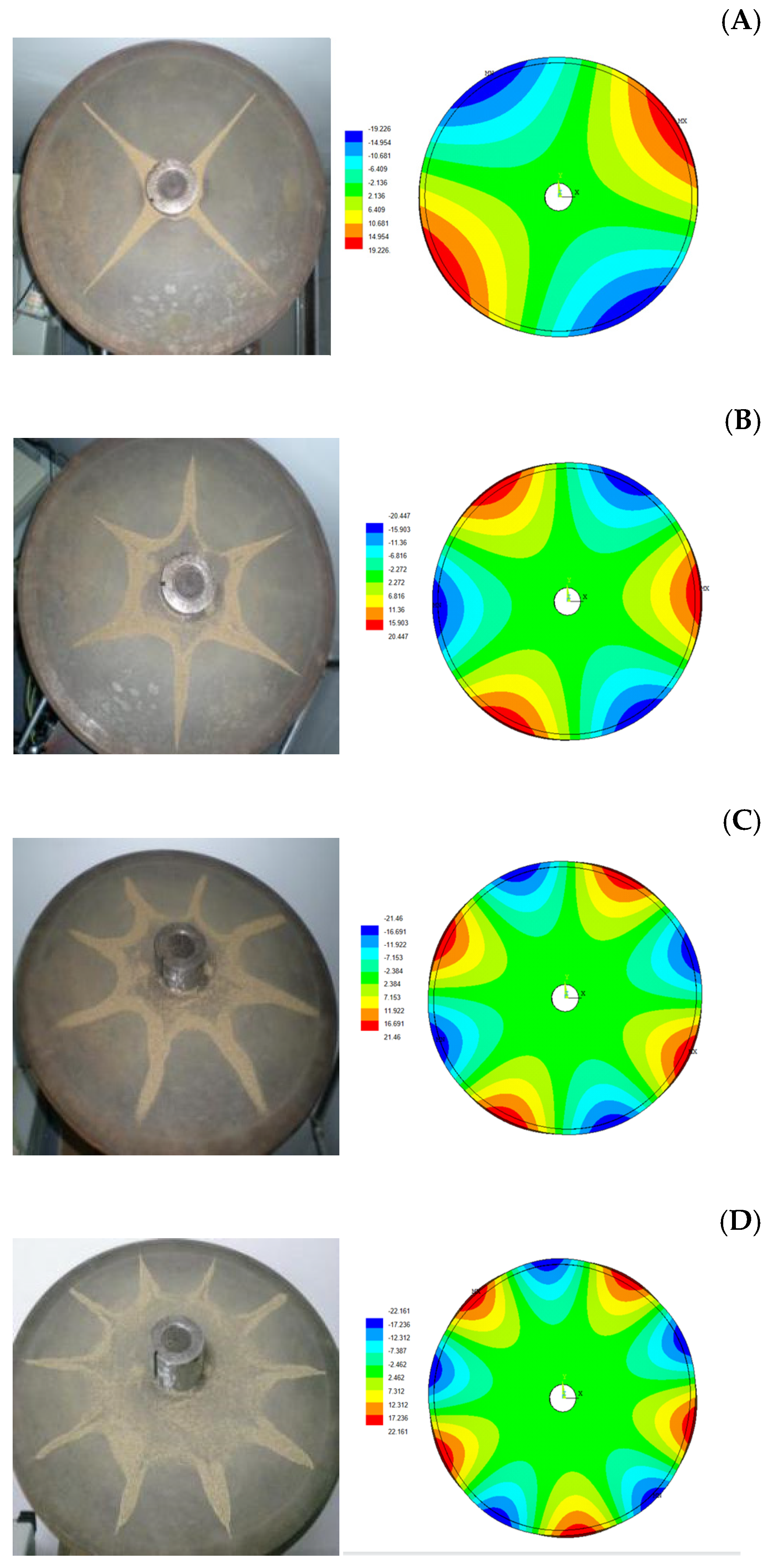
Sprinkle fine sand evenly on the horizontally placed disk, adjust the frequency of the signal generator, slowly increase from 20Hz, so that the exciter will excite the disk at a certain excitation frequency, until a clear and stable sand shape appeared on the disk (before the orderly motion of the fine sand was seen, and the amplitude of the motion gradually increased), and recorded the corresponding vibration mode of the sand at this time, the frequency of the corresponding signal generator and the waveform corresponding to the oscilloscope. The output frequency of the signal generator continued to increase until the vibration mode of multi-set vibrating sand was obtained, and the corresponding frequency of different sand forms and the waveform on the oscilloscope were also recorded. This sand shape was formed by the nodal line or nodal circle formed by flowing into the minimum amplitude region or static region of the vibrating fine sand in the large amplitude region. The comparison between the four types of sand type m = 2, 3, 4, 5 and the finite element analysis results is shown in Figure 3.
The modal frequencies corresponding to the 1st, 4th, 7th, 12th and 16th finite element analysis results are extracted. Comparison of sand shape frequency between the simulated disk test and finite element calculation frequency is shown in Table 2.
The experimental results are consistent with the finite element calculation, which verifies the accuracy of the finite element analysis. Only the linear mode of m = 2, 3, 4, 5 joints can be measured in the test. Because the test adopts the single point excitation method, and the simulated disk thickness is larger than the simulated disk diameter, and the simulated disk strength is large, it is difficult to achieve the phenomenon of pitch circle. Therefore, the optimal thickness and shape of the disk can be calculated in a targeted manner. When the simulated disk is in joint line vibration, the amplitude of the simulated disk will be consistent on the symmetric side. Therefore, the open balance holes of the disk are usually not even but odd (5 or 7) to avoid cracking and damage to the simulated disk caused by the concentrated stress. When the simulated disk is in the mode frequency, the amplitude of the symmetrical part on the edge of the simulated disk increases obviously and the amplitude of the connected blade on the disk increases obviously, which will cause the dynamic and static collision of the unit, and the fatigue deformation and even damage the disk system if the vibration continues for a long time.
4. The Influence of Detuning Parameters on Bladed Disk System Is Analyzed
4.1. Finite Element Analysis of the Disc System
On the edge of the disk 18 blades were evenly installed, with two adjacent blades having an installation angle of 20°, and the edge of the blade root and disk along the disk radial rigid connection with the two rivets. The thickness of each blade was 6 mm, width was 18 mm and height was 162 mm. The blade root was closely matched with the outer edge of the disc. The blade root height was 10 mm and the thickness of both sides of the blade root was 2 mm. A keyway with a diameter of 6 mm was opened at a distance of 32 mm from the top of the blade, with a length of 80 mm and a diameter of 6 mm at both ends of the keyway. The main purpose of this keyway is to add the counterweight bolts of different mass on it, and the position of the counterweight bolts can be changed, with the maximum displacement of 80 mm. We added 18 blades to the disk to form the bladed disk system, and the geometric model of the bladed disk system is shown in Figure 4. The blade shape and blade installation diagram are shown in Figure 5. In the figure, the small counterweight bolts on the blades are the schematic diagram for adding different mass and different positions on the blades.
By restricting the position of the central hole of the bladed disk system the first 100 vibration frequencies of the disc system test device were obtained by finite element calculation, as shown in Figure 6. It can be seen from Figure 6 that a frequency steering phenomenon occurs in the modal changes of the bladed disk system, that is, the system characteristic value trajectory first converges with some system characteristic parameters, but does not intersect, and then separates. It can be seen that with the increase of order, the natural frequency is roughly divided into six approximately horizontal regions and five climbing regions, which is more obvious at high frequency than at low frequency. The frequency in the horizontal region is highly dense, and the dominant blade vibration mode is mainly in this region. Five climbing regions are frequency steering regions, and the disk leads the vibration mode.
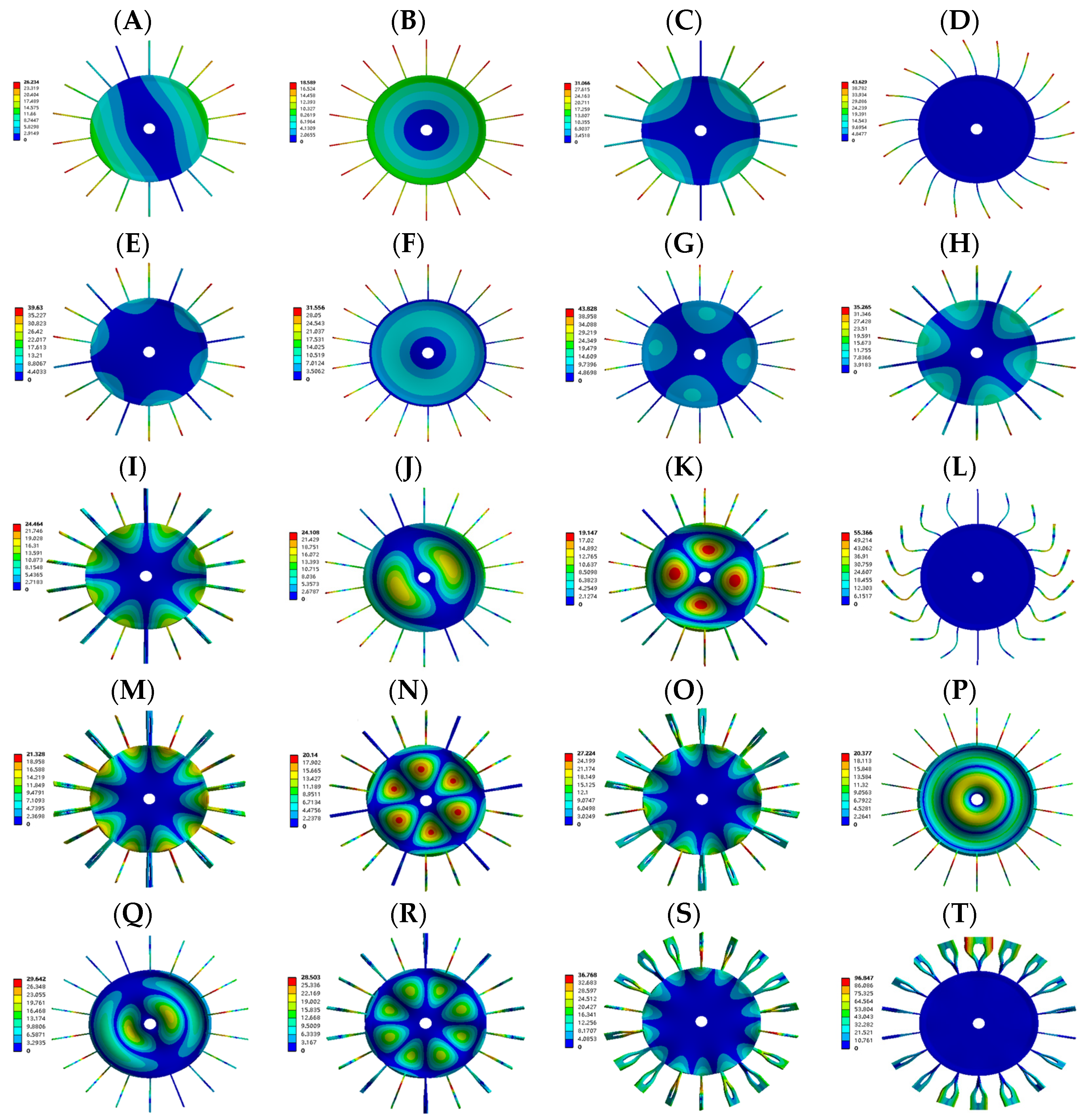
As an axial symmetric system, the bladed disk system must have a heavy root, which is not considered here. The typical mode of vibration in the first 100 climbing zones is extracted, as shown in Figure 7. In the figure, m represents the pitch number of the disk system and n represents the pitch number of the disk system. With the increase of the order, the vibration frequency of the bladed disk system increases, and the number of pitch diameter and pitch circle increases gradually. (A) is a 1st-order vibration mode with a vibration frequency of 65.517 Hz. The bladed disk system has only one pitch path. (B) is the mode of 3rd order vibration with the vibration frequency of 86.308 Hz. The disc system has no pitch diameter and circle, and the disc expands radially. (C) is the mode of 4th order vibration with the vibration frequency of 117.22 Hz. (D) is the mode of 6th order vibration with the vibration frequency of 180.05 Hz. The bladed disk system has no pitch diameter and circle. (E) is the mode of 24th order vibration with the vibration frequency of 241.34 Hz. (F) is the mode of 28th vibration with the vibration frequency of 331.02 Hz.
In the same way, as long as the excitation frequency is large enough, the bladed disk system will have different vibration modes with different pitch diameters and pitch circles. Generally, the bladed disk system is mainly subject to low-order vibration, and the frequency of steam-induced vibration will be up to 5 times the power frequency. The study of a low-order bladed disk system vibration is particularly important. Combined analysis of Figure 6 and Figure 7, the vibration of the bladed disk system corresponding to the horizontal area in Figure 6 is mainly manifested as the irregular vibration of the blades. In this interval, the disk is basically not vibrating, and the vibration amplitude of individual blades is relatively obvious.
4.2. Design of Bladed Disk System Parameter Variation
The change of blade mass in the bladed disk system will lead to the change of the inherent characteristics of the bladed disk system, such as blade crack, blade scale formation and blade detachment. Ten different working conditions were set up to discuss the factors influencing the vibration characteristics of the bladed disk system.
The design of different working conditions is as follows: the modal results and vibration modes of the bladed disk system and the original disk were compared and analyzed, and the differences in modal frequency, vibration mode and amplitude between the bladed disk system and the disk system were found. The above, middle and lower positions of the groove of a single blade were aggravated, the weight of which remained unchanged, and the variation of modal frequency, vibration mode and amplitude of the bladed disc system was discussed and analyzed. For each angle (60°, 120°, 180°) of the double blades that is aggravating, we discuss bladed disk system modal frequency, vibration mode and the change of amplitude. Different mass intensification was carried out at the same position of the same blade. One third (6 pieces) of the blades at the adjacent position of the whole disc system were removed to discuss and analyze the variation of modal frequency, vibration mode and amplitude of the disc system. The mode frequency, mode type and amplitude of the low-frequency vibration were still considered, and the first 16 mode vibration frequencies under 10 different conditions were intercepted, as shown in Table 3. The mode frequency of the corresponding bladed disk system under different conditions is shown in Figure 8.
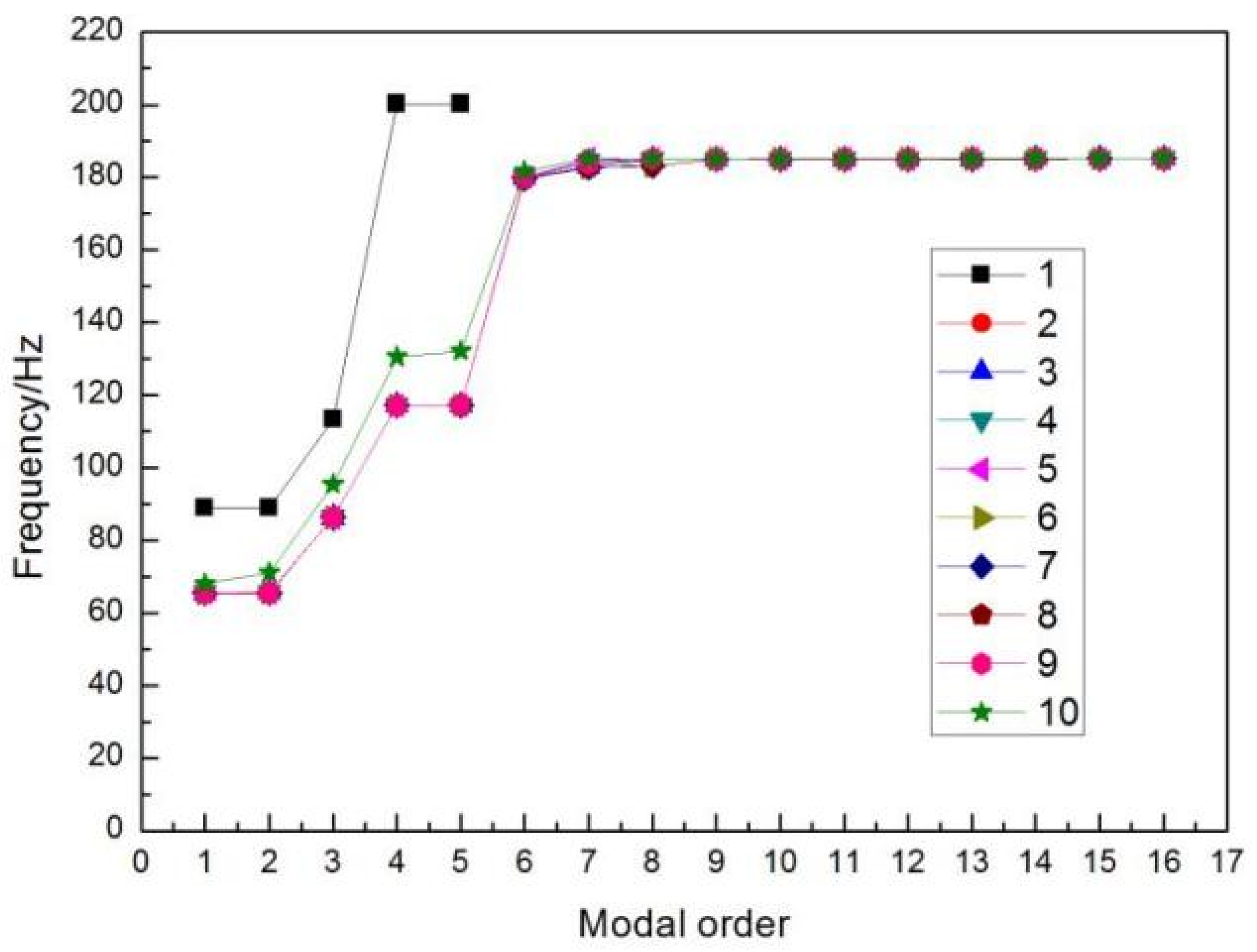
In Figure 8, Curve 1 represents the modal frequency corresponding to a different order of the disk; Curve 2 represents the modal frequency corresponding to a different order of the bladed disk system; Curve 3 represents the modal frequencies of different orders when the top of a blade keyway of a blade disk system is increased by 1.7 g; Curve 4 represents the modal frequencies of different orders when the middle part of a blade keyway of a bladed disk system is increased by 1.7 g; Curve 5 represents the modal frequencies of different orders when the bottom of a blade keyway on the bladed disc is weighted by 1.7 g; Curve 6 represents the modal frequencies of different orders when a certain double blades are 60° each other and the top of the blade keyway is weighted by 1.7 g respectively; Curve 7 represents the modal frequencies of different orders when a certain double blades are 120° each other and the top of the blade keyway is weighted by 1.7 g respectively; Curve 8 represents the modal frequencies of different orders when a certain double blades are 180° each other and the top of the blade keyway is weighted by 1.7 g respectively; Curve 9 represents the modal frequencies of different orders when the top of a blade keyway on the blade disk is weighted 5.1 g; Curve 10 represents the modal frequency of blade shedding of 6 adjacent blades in different order. Based on condition 2, deviation analysis was conducted between conditions 3–10 and condition 2, as shown in Figure 9.
According to Figure 8 and Figure 9, it can be seen that the vibration frequency of the bladed disk system decreases after 18 blades are added to the original disk. The effect of different positions on the single blade on the modal frequency of the bladed disk system is very small. The larger the weight at the same position, the smaller the frequency. When the blade falls off, the modal frequency of the disk system increases greatly. In the above study of different working conditions, the change of an order 6–9th is more obvious than that of other order.
4.3. Analysis on the Influence of Structural Changes of Bladed Disk System
4.3.1. Modal Analysis of Disk and Bladed Disk System
The 1st, 3rd, 4th, and 6th-order low-order modes of the disk and blade disk system were extracted respectively for comparison, as shown in Figure 10. Among them, the first and fourth order of the disk and bladed disk system have the phenomenon of stress root. As can be seen from Figure 10 disk and modal vibration mode of the bladed disk system have the same trend, in the figure, in turn, show the section line m = 1, radial expansion, the section line m = 2 corresponding to the vibration mode of the figure, the 6th order modes are different. The 6th order of the disk is the mode pattern diagram of the pitch line m = 3, the bladed disk system is the mode of disk static, blade vibration, and as mentioned earlier, the bladed disk system’s 6th order to 23rd order for irregular blade vibration. As the number of nodes increases, the amplitude of vibration increases gradually, but the amplitude of radial expansion is less than the amplitude of node m = 1. The mass of the bladed disk system is larger than that of the disk, which leads to the reduction of the modal frequency of the bladed disk system. The bladed disk system can be regarded as the result of an increase in the diameter of the disk on the basis of the original disk. With the increase of the diameter of the blade disk system, the amplitude of the corresponding vibration mode will increase compared with the amplitude of the original disk. As the diameter of the bladed disk system increases, the amplitude of the corresponding vibration mode will be higher than that of the original disk. After the 6th stage of the disc, it continued to develop according to the trend that the number of nodal lines and nodal circles increased alternately. By contrast, the modal frequency was basically unchanged from the 6th to the 23rd stage of the bladed disc system.
4.3.2. The Influence of the Quality Change of Single Blade on the Modal Frequency of the Bladed Disk System
For the disk system studied in this paper, the blade at the top of the plane was selected for the study. The counterweights with the same mass of 1.7 g were added to the upper, middle and lower positions of the blade keyway for modal analysis. Then, the upper end of the blade keyway was fixed, adding 5.1 g of counterweight, and compared with the above working conditions. The typical modal modes of the above four working conditions and the initial state of the bladed disk system (without counterweight) were extracted, as shown in Figure 11. Each column, from top to bottom, was a single blade keyway without weight, a counterweight with 1.7 g at the top, middle and bottom, and a counterweight with 5.1 g at the top. It can be seen from Figure 9 that the frequency deviation of 6th, 7th and 8th modes is large when mass changes, so the three modes are extracted for comparison.
It can be concluded from Figure 11 that the modes of the 6th, 7th and 8th order of the bladed disk system are all impeller static and blade vibration. At this point, the amplitude of blade vibration is much greater than the amplitude of the dominant vibration of the previous 5th-order disk. The vibration amplitude of the counterweight added to the tip of the blade is larger, and the corresponding vibration frequency is slightly smaller. The larger the mass at the same position, the smaller the modal frequency and the larger the maximum amplitude.
4.3.3. The Effect of the Double Blades Angle Aggravation on the Modal Frequency of the Bladed Disk System
For the blade disc system studied in this paper, the top blade of the plane was selected as the reference, and three angles of double blades were selected to weigh at the top at the same time. The three kinds of weight were compared with the typical mode shapes of the initial state of the blade disc system (without counterweight), as shown in Figure 12.
Each column from top to bottom in turn is initial state, double blades are 60° to each other, and the top end adds 1.7 g counterweight; double blades are 120° to each other, and the top end adds 1.7 g counterweight; and double blades are 180° to each other, and the top end adds 1.7 g counterweight. It can be seen from Figure 12 that the frequency deviation of modes 6, 7 and 8 when the double blades are weighted at the top of the angle of mutual formation is large, so the vibration modes of the third order are extracted for comparison.
It can be concluded from Figure 12 that the modes of the 6th, 7th and 8th order of the bladed disk system are all impeller static and blade vibration. At this point, the amplitude of blade vibration is much greater than the amplitude of the dominant vibration of the first 5 stages of the disk. The modal vibration frequency of the double blades of the bladed disk system with counterweight is lower than the modal vibration frequency without counterweight, and there is no obvious law of amplitude change.
4.3.4. The Influence of Blade Loss on the Modal Frequency of the Blade Disk System
Taking the top blade on the plane as the reference, one-third (6 pieces) of the blade were removed clockwise for the finite element modal analysis, and the modal modes and modal frequencies obtained were compared with the initial state of the bladed disk system (without weight). As shown in Figure 13, typical modes are extracted for comparative analysis. The modes 2, 3, 4, 6, 24 in the initial state of the first column of the bladed disk, and the modes 2, 3, 4, 6, 19 in the case of the second column of missing blades are similar to the mode of the initial state.
Combined with Figure 9 and Figure 10, Table 3, it can be concluded that when part of the blade of the bladed disk system is missing, the modal shape is generally consistent with the change trend of the initial state. Due to the absence of blades, the mass distribution of the bladed disk system is not uniform, resulting in the change of the corresponding modal mode, and the offset of nodal line and nodal circle is no longer symmetrical distribution. Due to the absence of blades, the mass of the dissonant bladed disk decreases significantly, leading to a significant increase in the modal frequency of the bladed disk system, especially at lower order. The blade loss causes the bladed disk system to be asymmetrical, which leads to the increase of vibration amplitude of each order. At the order 6–23, blade vibration is still dominant in the disc system, and the disk is still at rest. The loss of blades will lead to quality imbalance of the disc system and the loss of the characteristic of axial symmetry.
5. Conclusions
Taking the rotor disk system of aero-engines as the research object, the modal calculation of the rotor disk system was carried out based on the group theory, and the simulated disk vibration mode was represented by the movement of fine sand on the disk. The experimental vibration mode was compared with the finite element calculation results to verify the reliability of finite element analysis. The comparative analysis of the modal of the disk and the bladed disk system, the effect of the change of the quality of a single blade on the bladed disk system’s modal frequency, the effect of the increase of the angle of the interaction between double blades on the bladed disk system’s modal frequency, and the effect of bladed loss on the modal frequency of the bladed disk system were analyzed, and the following conclusions were drawn.
- The modal test results of the disk were basically consistent with the finite element calculation results, which verified the accuracy of the finite element analysis. The vibration shape trends of the bladed disk system and the disk were basically consistent, and the modal frequencies of the bladed disk system were all smaller than the modal frequencies of the disk.
- When the mass on different parts of a single blade increased, the vibration amplitude corresponding to the addition of the counterweight on the top of the blade increased, and the corresponding vibration frequency was not obvious; the greater the mass of the counterweight at the same position, the slightly smaller modal frequency, the corresponding maximum amplitude increases more obviously.
- The modal vibration frequency of the double blades at an angle to each other and the counterweight was less than the modal vibration frequency when the counterweight was not added. The mode of the blade was affected by the position of the weighted blade, and the amplitude change had no obvious law.
- When the bladed disk system vibrated at low frequency, the disk vibration was dominant one, and the blades vibrated with the disk. In a certain frequency range, the disk would not vibrate, and each blade vibrated irregularly. During the working process, use of the blade disk should be avoided in this working area for a long time, otherwise it will lead to fatigue damage of some blades and even damage to the blades.
Author Contributions
Conceptualization, H.P. and T.Z.; methodology, H.P. and Y.W.; software, Y.W.; validation, H.P.; formal analysis, Y.W.; investigation, H.P. and T.Z.; resources, H.P.; data curation, Y.W.; writing—original draft preparation, H.P.; writing—review and editing, Y.W.; visualization, Y.W.; supervision, T.Z.; project administration, H.P. and T.Z.; funding acquisition, H.P. and T.Z. All authors have read and agreed to the published version of the manuscript.
Funding
This research was funded the National Natural Science Foundation of China, grant number 51775093, China Postdoctoral Science Foundation, grant number 2019M661125, Doctorate Start Foundation of Liaoning Provincial, grant number 20180540077, Scientific Research Funding Project of Liaoning Education Department, grant number Jl-2003, Science and Technology Program of Shenyang, grant number 20-206-4-16, Science and Technology Innovation Team Support Program of Shenyang middle-aged and young people, grant number RC190342.
Institutional Review Board Statement
Not applicable.
Informed Consent Statement
Not applicable.
Data Availability Statement
Data sharing not applicable.
Conflicts of Interest
The authors declared no conflict of interest.
References
- Sever, I.A.; Petrov, E.P.; Ewins, D.J. Experimental and numerical investigation of rotating blade-disk system forced response using underplatform friction dampers. J. Eng. Gas Turbines Power 2007, 130, 323–333. [Google Scholar]
- Petrov, E.P. A method for forced response analysis of mistuned blade-disk systems with aero dynamic effects included. J. Eng. Gas Turbines Power 2010, 132, 375–386. [Google Scholar] [CrossRef]
- Castanier, M.P.; Pierre, C. Modeling and analysis of mistuned blade-disk system vibration: Status and emerging directions. J. Propuls. Power 2006, 22, 384–396. [Google Scholar] [CrossRef]
- Bladh, R.; Pierre, C.; Castanier, M.P.; Kruse, M.J. Dynamic response predictions for a mistuned industrial turbomachinery rotor using reduced-order modeling. J. Eng. Gas Turbines Power 2002, 124, 311–324. [Google Scholar] [CrossRef]
- Wang, H.J.; He, E.M. Exploring key features of blade mistuning effects on vibrationc haracteristics of blade-disk systems. J. Northwest. Polytech. Univ. 2009, 27, 645–650. [Google Scholar]
- Wang, A.L.; Sun, B.H. Analysis of natural vibration localization of random mistuned blade-disk system with grouped blades. China Mech. Eng. 2011, 7, 771–775. [Google Scholar]
- Liao, H.T.; Wang, J.J.; Li, Q.H. Mistuned forced response characteristics analysis of mistuned multi-stages blade-disk systems. J. Vib. Shock. 2011, 3, 22–29. [Google Scholar]
- Liao, H.T.; Wang, J.J.; Li, Q.H. Mistuning characteristics analysis of mistuned blade-disk system assemblies. J. Aerosp. Power 2010, 1, 160–168. [Google Scholar]
- Liao, H.T.; Wang, J.J.; Wang, S.; Li, Q.H. Experimental investigation of the worst-case mode localization for a mistuned blade-disk system assemblies. J. Aerosp. Power 2011, 8, 1847–1854. [Google Scholar]
- Liao, H.T.; Wang, S.; Wang, J.J.; Li, Q.H. Tests for forced response localization of a mistuned blade-disk system assembly. J. Vib. Shock 2012, 1, 29–34. [Google Scholar]
- Zhang, H.; Zhao, T.Y.; Zhang, H.Y.; Pan, H.G.; Yuan, H.Q.; Ma, H.; Yin, F.; Tai, X.; Kou, H.; Yuan, H.; et al. Dynamic characteristics of mistuned bladed disk system under rub-impact force. Adv. Mech. Eng. 2020, 12. [Google Scholar] [CrossRef]
- Yu, C.B.; Wang, J.J.; Li, Q.H. Probability characteristics for vibratory mode of detuned blade-disk system assemblies. J. Aerosp. Power 2009, 9, 2040–2045. [Google Scholar]
- Yu, C.B.; Wang, J.J.; Li, Q.H. Probability characteristics for response localization of mistuned blade-disk system assemblies. J. Aerosp. Power 2010, 9, 2006–2012. [Google Scholar]
- Wang, J.J.; Yu, C.B.; Yao, J.R.; Li, Q.H. Vibratory mode localization factors of mistuned blade-disk system assemblies. J. Propuls. Technol. 2009, 4, 457–461, 473. [Google Scholar]
- Wang, J.J.; Xu, J.D.; Li, Q.H. Analytical Models of Mistuned blade-disk system Assembles—A Review. Turbine Technol. 2004, 4, 256–259. [Google Scholar]
- Box GE, P.; Wilson, K.B. On the experimental attainment of optimum conditions (with discussion). J. R. Stat. Soc. 1951, B13, 1–45. [Google Scholar]
- Calleja, A.; Alonso, M.A.; Fernández, A.; Tabernero, I.; Ayesta, I.; Lamikiz, A.; López de Lacalle, L.N. Flank milling model for tool path programming of turbine blisks and compressors. Int. J. Prod. Res. 2015, 3, 3354–3369. [Google Scholar] [CrossRef]
- Artetxe, E.; Olvera, D.V.; López de Lacalle, L.N.; Campa, F.J.; Olvera, D.; Lamikiz, A. Solid subtraction model for the surface topography prediction in flank milling of thin-walled integral blade rotors (IBRs). Int. J. Adv. Manuf. Technol. 2017, 90, 741–752. [Google Scholar] [CrossRef]
- Rahimi, M.; ZiaeiRad, S. Uncertainty treatment in forced response calculation of mistuned blade-disk system. Math. Comput. Simul. 2009, 7, 1–12. [Google Scholar]
- Vargiu, P.; Firrone, C.M.; Zucca, S.; Gola, M.M. A reduced order model based on sector mistuning for the dynamic analysis of mistuned blade-disk systems. Int. J. Mech. Sci. 2011, 53, 639–646. [Google Scholar] [CrossRef] [Green Version]
- Zhao, T.Y.; Ma, Y.; Zhang, H.Y.; Pan, H.G.; Cai, Y. Free vibration analysis of a rotating graphene nanoplatelet reinforced pre-twist blade-disk assembly with a setting angle. Appl. Math. Model. 2021, 93, 578–596. [Google Scholar] [CrossRef]
- Zhao, T.Y.; Jiang, L.P.; Pan, H.G.; Yang, J.; Sritawat, K. Coupled free vibration of a functionally graded pre-twisted blade-shaft system reinforced with graphene nanoplatelets. Compos. Struct. 2020, 262, 113362. [Google Scholar] [CrossRef]
- Zhao, T.Y.; Ma, Y.; Zhang, H.Y.; Yang, J. Coupled Free Vibration of Spinning Functionally Graded Porous Double-Bladed Disk Systems Reinforced with Graphene Nanoplatelets. Materials 2020, 13, 5610. [Google Scholar] [CrossRef]
- Choi, B. Pattern optimization of intentional blade mistuning for the reduction of the forced response using genetic algorithm. KSME Int. J. 2003, 17, 966–977. [Google Scholar] [CrossRef]
- Choi, W.; Storer, R.H. Heuristic algorithms for a turbine-blade-balancing problem. Comput. Oper. Res. 2004, 31, 1245–1258. [Google Scholar] [CrossRef]
- Polvorosa, R.; Suárez, A.; LNLópez de Lacalle Cerrillo, I.; Wretland, A.; Veiga, F. Tool wear on nickel alloys with different coolant pressures: Comparison of Alloy 718 and Waspaloy. J. Manuf. Process. 2017, 26, 44–56. [Google Scholar] [CrossRef]
- Suárez, A.; de Lacalle, L.N.L.; Polvorosa, R.; Veiga, F.; Wretland, A. Effects of high-pressure cooling on the wear patterns on turning inserts used on alloy IN718. Mater. Manuf. Process. 2017, 32, 678–686. [Google Scholar] [CrossRef]
- Scarselli, G.; Lecce, L.; Castorini, E. Mistuning effects evaluation on turbomachine dynamic behaviour using genetic algorithms. Int. J. Acoust. Vib. 2011, 32, 354–358. [Google Scholar] [CrossRef]
- Yang, X.; Xing, J.H. Optimum arrangement of rotor blades based on genetic algorithms. Comput. Simul. 2008, 25, 94–98. [Google Scholar]
- Chen, X.M.; Wang, K. The sort algorithm for the air-compressor blade based on simulated annealing partheno genetic algorithm. J. Southwest China Norm. Univ. (Nat. Sci. Ed.) 2009, 34, 156–158. [Google Scholar]
- Zhan, D.S. Optimum arrangement of blades based on genetic algorithm with complex restraints. Mach. Des. Manuf. 2010, 9, 12–14. [Google Scholar]
- Yue, J.M.; Bai, H.B.; Liu, Z.C.; Liao, C.H. Simulation search algorithm of the computer vanes with progressively adjusted optimization. J. Sichuan Univ. Sci. Eng. 2005, 18, 88–94. [Google Scholar]
- Zhao, T.Y.; Cui, Y.S.; Pan, H.G.; Yuan, H.Q.; Yang, J. Free vibration analysis of a functionally graded graphene nanoplatelet reinforced disk-shaft assembly with whirl motion. Int. J. Mech. Sci. 2021, 197, 106335. [Google Scholar] [CrossRef]
- Zhao, T.Y.; Cui, Y.S.; Pan, H.G.; Yuan, H.Q.; Yang, J. Free vibration analysis of a spinning porous nanocomposite blade reinforced with graphene nanoplatelets. J. Strain Anal. Eng. Des. 2021. [Google Scholar] [CrossRef]
- Zhao, T.Y.; Jiang, Z.Y.; Zhao, Z.; Xie, L.Y.; Yuan, H.Q. Modeling and free vibration analysis of rotating hub-blade assemblies reinforced with graphene nanoplatelets. J. Strain Anal. Eng. Des. 2021. [Google Scholar] [CrossRef]
- Yuan, H.Q.; Zhang, L.; Han, Q.K. Reducing vibration mounting optimization for aero-engine rotor mistuned blade. J. Vib. Meas. Diagn. 2011, 31, 647–651. [Google Scholar]
- Zhao, T.Y.; Yuan, H.Q.; Yang, W.J.; Zhang, H.Y. Mistuned blade arrangement with non-linear friction based on parallel annealing algorithm. J. Aerosp. Power 2016, 31, 1053–1064. [Google Scholar]
- Pan, H.G.; Zhao, T.Y.; Yuan, H.Q.; Li, B.B. Iterative response surface joint algorithm analysis of optimization arrangement on mistuned blades. J. Vibroeng. 2017, 19, 1298–1302, 1314. [Google Scholar]
- Pan, H.G.; Yuan, H.Q.; Zhao, T.Y.; Wang, G.D. Modal testing experiment based on simulation impeller of turbine. J. Northeast. Univ. (Nat. Sci.) 2017, 9, 1298–1302. [Google Scholar]
Figure 1.
Experiment device of the modal impeller test.

Figure 2.
Mesh and geometric model of whole simulation impeller.

Figure 3.
The sand pattern is compared with the results of finite element analysis. (A) m = 2, (B) m = 3, (C) m = 4, (D) m = 5.
Figure 3.
The sand pattern is compared with the results of finite element analysis. (A) m = 2, (B) m = 3, (C) m = 4, (D) m = 5.

Figure 4.
Bladed disk geometric model.

Figure 5.
Blade shape and blade installation schematic.

Figure 6.
Order times mode frequency of bladed disk system.

Figure 7.
Order mode of vibration of bladed disk system (A) m = 1, n = 0, (B) m = 0, n = 0, (C) m = 2, n = 0, (D) m = 0, n = 0, (E) m = 3, n = 0, (F) m = 0, n = 1, (G) m = 2, n = 0, (H) m = 3, n = 0 (I) m = 4, n = 0, (J) m = 1, n = 1, (K) m = 2, n = 1, (L) m = 0, n = 0, (M) m = 5, n = 0, (N) m = 3, n = 1, (O) m = 6, n = 0, (P) m = 0, n = 2, (Q) m = 1, n = 2, (R) m = 4, n = 1, (S) m = 7, n = 0, (T) m = 0, n = 0.

Figure 8.
Modal frequency of bladed disk system under different working conditions.

Figure 9.
Modal frequency deviation of blade-disk system in different working conditions.

Figure 10.
Contrast between disk and bladed disk system vibration mode (A) 1st low-order mode (B) 3rd low-order mode (C) 4th low-order mode (D) 6th low-order mode.
Figure 10.
Contrast between disk and bladed disk system vibration mode (A) 1st low-order mode (B) 3rd low-order mode (C) 4th low-order mode (D) 6th low-order mode.

Figure 11.
Mode vibration contrast of bladed disk system mass change (A) 6th mode (B) 7th mode (C) 8th mode.
Figure 11.
Mode vibration contrast of bladed disk system mass change (A) 6th mode (B) 7th mode (C) 8th mode.

Figure 12.
Comparison of modes with different double blades’ angle of bladed disk system (A) 6th mode (B) 7th mode (C) 8th mode.
Figure 12.
Comparison of modes with different double blades’ angle of bladed disk system (A) 6th mode (B) 7th mode (C) 8th mode.

Figure 13.
Comparison of modes with blades missing in bladed disk system.


Table 1.
Main characteristic parameters of experimental apparatus.
| Device Name | Model | Size/mm (Length × Width × Height) | Range of Use/kHz | The Main Features |
|---|---|---|---|---|
| Signal generator | SFG-1023 | 251 × 291 × 91 | 0~3000 | Three output waveforms, 5 W power output adjustable |
| Power amplifier | GF200-4 | 440 × 370 × 160 | 0~10 | It has signal clipping, overcurrent and overtemperature protection indication |
| Vibrator | JZQ20 | 190 × 190 × 175 | 0~2 | The maximum excitation force was 10 kg and the excitation amplitude was ±5 mm |
| Vibration pickup | electromagnetic coil | 80 × 80 × 60 | 0~2 | Power: 200 W, non-contact mounting |
| Oscilloscope | GOS-620 | 310 × 455 × 150 | 0~20,000 | Dual channel, alternating trigger, high sensitivity, 20 MHz bandwidth |
Table 2.
The result comparison of simulation impeller sand frequency and finite element calculation.
Table 2.
The result comparison of simulation impeller sand frequency and finite element calculation.
| Variable | Section Line m = 1 | Section Line m = 2 | Section Line m = 3 | Section Line m = 4 | Section Line m = 5 |
|---|---|---|---|---|---|
| test sand frequency/Hz | — | 194.5 | 462.1 | 837.9 | 1329.6 |
| the finite element calculation frequency/Hz | 88.998 | 200.251 | 467.163 | 848.601 | 1343 |
| finite element and experimental error/% | — | 2.96 | 1.10 | 1.28 | 1.01 |
Table 3.
Modal frequency of bladed disk system under different working conditions. Unit:Hz.
| Order Time | Modal Frequency under Different Operating Conditions | |||||||||
|---|---|---|---|---|---|---|---|---|---|---|
| Disk | Bladed Disk System | Individual Blade Tip Balancing | Middle Weight of Single Blade | Counter Weight of Single Blade End | Double Blades Weight at the Top 60° | Double Blades Weight at the Top of 120° | Double Blades Weight at the Top of 180° | 3 Times the Weight at the Tip of a Single Blade | One Third of the Adjacent Blade Is Missing | |
| 1 | 89.00 | 65.52 | 65.50 | 65.51 | 65.51 | 65.48 | 65.49 | 65.48 | 65.46 | 68.08 |
| 2 | 89.00 | 65.54 | 65.52 | 65.53 | 65.53 | 65.52 | 65.50 | 65.52 | 65.51 | 71.10 |
| 3 | 113.37 | 86.31 | 86.29 | 86.30 | 86.30 | 86.27 | 86.27 | 86.27 | 86.26 | 95.41 |
| 4 | 200.25 | 117.22 | 117.16 | 117.21 | 117.20 | 117.13 | 117.13 | 117.10 | 117.10 | 130.52 |
| 5 | 200.25 | 117.22 | 117.22 | 117.22 | 117.22 | 117.19 | 117.19 | 117.22 | 117.22 | 132.14 |
| 6 | - | 180.05 | 179.83 | 180.01 | 180.07 | 179.64 | 179.64 | 179.65 | 179.94 | 181.70 |
| 7 | - | 185.00 | 182.95 | 184.49 | 185.01 | 182.76 | 182.74 | 182.78 | 183.88 | 185.12 |
| 8 | - | 185.03 | 185.01 | 185.01 | 185.03 | 183.16 | 183.17 | 183.22 | 185.01 | 185.05 |
| 9 | - | 185.05 | 185.03 | 185.03 | 185.05 | 185.01 | 185.01 | 185.01 | 185.03 | 185.06 |
| 10 | - | 185.05 | 185.05 | 185.05 | 185.06 | 185.03 | 185.03 | 185.03 | 185.05 | 185.09 |
| 11 | - | 185.06 | 185.06 | 185.06 | 185.06 | 185.05 | 185.05 | 185.05 | 185.06 | 185.10 |
| 12 | - | 185.06 | 185.06 | 185.06 | 185.07 | 185.06 | 185.06 | 185.06 | 185.06 | 185.11 |
| 13 | - | 185.08 | 185.07 | 185.07 | 185.09 | 185.06 | 185.06 | 185.06 | 185.08 | 185.12 |
| 14 | - | 185.09 | 185.09 | 185.09 | 185.10 | 185.07 | 185.07 | 185.07 | 185.09 | 185.15 |
| 15 | - | 185.10 | 185.10 | 185.10 | 185.11 | 185.09 | 185.09 | 185.09 | 185.10 | 185.16 |
| 16 | - | 185.11 | 185.11 | 185.11 | 185.11 | 185.10 | 185.10 | 185.10 | 185.11 | 185.17 |
Publisher’s Note: MDPI stays neutral with regard to jurisdictional claims in published maps and institutional affiliations. |
© 2021 by the authors. Licensee MDPI, Basel, Switzerland. This article is an open access article distributed under the terms and conditions of the Creative Commons Attribution (CC BY) license (https://creativecommons.org/licenses/by/4.0/).
Share and Cite
MDPI and ACS Style
Pan, H.; Wu, Y.; Zhao, T. Study on Influence of Multi-Parameter Variation of Bladed Disk System on Vibration Characteristics. Appl. Sci. 2021, 11, 3084. https://doi.org/10.3390/app11073084
AMA Style
Pan H, Wu Y, Zhao T. Study on Influence of Multi-Parameter Variation of Bladed Disk System on Vibration Characteristics. Applied Sciences. 2021; 11(7):3084. https://doi.org/10.3390/app11073084
Chicago/Turabian StylePan, Honggang, Yunshi Wu, and Tianyu Zhao. 2021. "Study on Influence of Multi-Parameter Variation of Bladed Disk System on Vibration Characteristics" Applied Sciences 11, no. 7: 3084. https://doi.org/10.3390/app11073084
Note that from the first issue of 2016, this journal uses article numbers instead of page numbers. See further details here.