
Enhanced Bit Repair IP Fast Reroute Mechanism for Rapid Network Recovery


1
Department of Infocomm Networks, University of Žilina, 010 26 Žilina, Slovakia
2
Department of Informatics, University of Žilina, 010 26 Žilina, Slovakia
*
Author to whom correspondence should be addressed.
Appl. Sci. 2021, 11(7), 3133; https://doi.org/10.3390/app11073133
Submission received: 12 March 2021
/
Revised: 25 March 2021
/
Accepted: 26 March 2021
/
Published: 1 April 2021
(This article belongs to the Section Electrical, Electronics and Communications Engineering)
Abstract
:The massive development of virtualized infrastructures, Internet of Things (IoT), and Wireless Sensor Network (WSN) in recent years has led to an increase in quality requirements for the management and reliability of underlay communication networks. Existing converged networks must therefore guarantee specific quantitative and qualitative parameters of different network communication services to meet customer requirements. However, the quality of the services operated is very negatively affected by an unpredictable failure of a communication link or a network node. In such situations, communication is typically interrupted for a period that is difficult to predict, and which can lead to significant financial losses and other negative effects. Internet Protocol Fast Reroute (IP FRR) technology was developed for these reasons. The paper presents the proposal of the new Enhanced Bit Repair (EB-REP) IP FRR mechanism, which offers significant improvements over its predecessor, the B-REP mechanism. The B-REP offers protection against a single failure and only for selected critical IP flows. The EB-REP provides advanced protection against multiple failures in a protected network domain and the protection can be provided for all network flows. The EB-REP calculates alternative paths in advance based on link metrics, but also allows the construction of alternative paths independently of them. The construction of alternative FRR paths uses a standardized tunneling approach via a unique field Bit-String. Thanks to these features, EB-REP is an advanced contribution to solving IP FRR-related problems, which enables the use of EB-REP in many network deployments, but especially in network solutions that require reliable data transmission.
1. Introduction
In 2020 and 2021, communication networks have faced and will face challenges due to the spread of the COVID-19 virus [1]. COVID-19 has moved most offline meetings and services into online spaces and led to a further radical increase in the traffic generated in existing IP networks [2]. Today, IP networks, as a true example of today’s converged networks, face the challenge of meeting the diverse requirements of a wide portfolio of communication services, whether used by humans or machines. The network is therefore required to meet very specific and diverse qualitative and quantitative parameters for a diverse range of services operated, where others are for real-time communication services [3], wireless sensor services [4,5,6,7,8,9], mission-critical services, Software-Defined Networking (SDN) [10] and other important systems such as intelligent transport systems [11]. These services, to provide the expected quality and functionality, have their critical network performance requirements, including delay, availability, jitter, and packet loss [12,13,14,15]. Moreover, all these factors are thus negatively affected by unpredictable links or node failures in the network. In this situation, a network device is unable to route data correctly based on its current information, as some of its routing information is no longer valid. Therefore, the network device (a router) must start a network convergence process, in which it informs the neighbors about the change and updates its routing knowledge based on the mutual exchange of current routing information. The length of the network convergence process is affected by the complexity of the network and the routing protocol used in the network. Until the process is complete, the routing of packets is performed based on outdated or missing entries, and many packets may be lost. Great efforts have been made to reduce the time required for a routing protocol to advertise information about network changes and recalculate the new set of shortest routes [14,15,16,17,18,19,20,21,22,23]. However, simply shortening the routing protocol timers to achieve faster network convergence is not recommended as this can lead to network destabilization by making the routing protocol too responsive [24,25,26]. To meet these complex requirements, it is therefore necessary for Internet Service Provider (ISP) to deploy and correctly use multiple solutions to ensure a reliable connection for the customers and the services they offer. One of the types of mechanisms that focus on situations of unexpected network failures is the IP Fast Reroute (hereinafter referred to as IP FRR or FRR) mechanisms (Figure 1). Addressing these issues, the IP Fast Reroute mechanisms have been developed to decrease the network convergence time and minimize traffic losses [27,28,29,30,31,32].
To achieve rapid traffic recovery, the first of the IP Fast Reroute mechanisms calculates an alternative path in advance, before the link or node fails. When a failure is detected, for example, detecting the loss of carrier, the FRR-enabled router immediately uses this backup path in response to the failure and forwards packets to a new neighboring router on the alternative path, rather than just starting convergence and calculating a new path, as it is common in traditional routed networks. Using current IP FRR approaches, the average routing recovery time ranges from 20 to 50 ms [33].
1.1. IP Fast Reroute Fundamentals
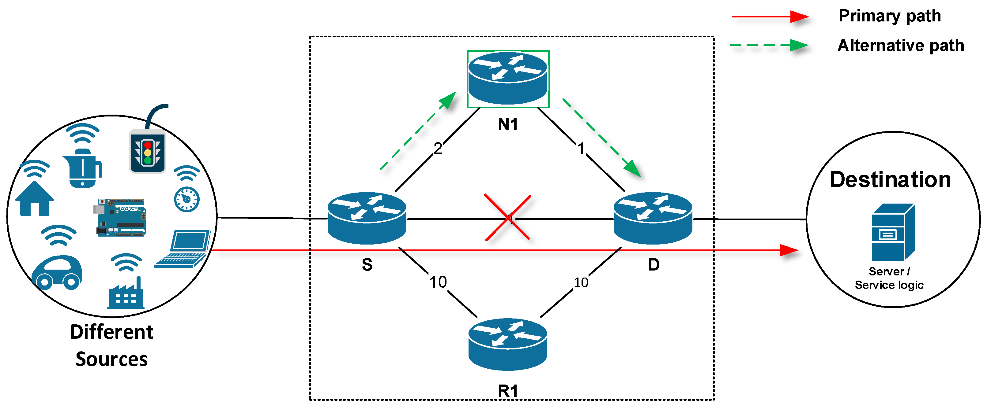
In this subsection, we will describe the elementary terminology related to the IP Fast Reroute technology, which will then be used throughout the paper. An example is shown in Figure 1. The source (S) router is a router that has detected a fault of a directly connected line or has detected the unavailability of a neighboring router. The S router activates a local FRR repair process and initiates FRR repair. This router is also referred to as the Point of Local Repair (PLR). FRR then distinguishes the destination (D) router, where the alternative path ends. It typically occurs in a situation where an alternative path is constructed through multiple network nodes, via a so-called multi-hop. Then, we have N1, N2, … N routers, which are also referred to as alternative next-hops. These additional routers form a given alternative path as the chain of forwarding next-hop nodes located on the path between routers S and D. Finally, we distinguish the router R, which is a router that is not actively involved in FRR repair.
In the case of connection failure detection, the following simplified IP FRR process takes place on a router. It can be divided into the following phases:
Zero phase (the preparation)—setting up the protected interface. The FRR mechanism then starts the calculation of alternative paths used in the case of failure on the protected lines.
First phase—detection of line error or neighbor unavailability by specialized FRR technology. At this phase, the FRR mechanism is activated.
Second phase—temporary modification of the routing information concerned by the FRR mechanism. At this phase, a precalculated alternative path is installed and used for data delivery. The FRR mechanism is active.
Phase three—the routing protocol updates the routing information in the background. The FRR mechanism still provides temporary routing information used to route packets, at least until the network convergence is complete. The FRR mechanism is active.
Fourth phase—the routing protocol has completed the necessary update of the routing information. The FRR mechanism is deactivated, and packets are routed using the information provided by the routing protocol.
1.2. Link Versus Node Protection
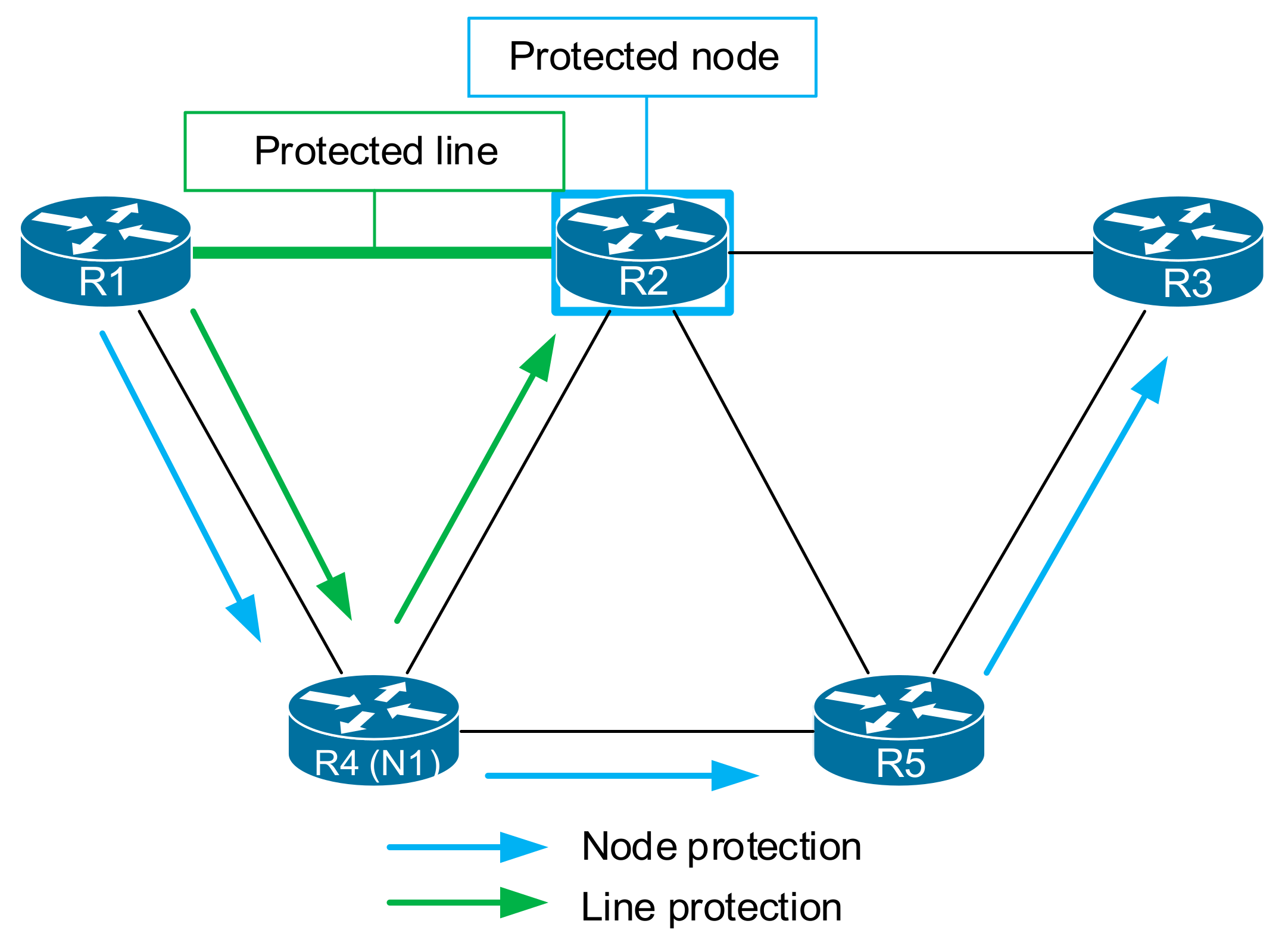
The operation of FRR is based on two basic principles, which are the focus of the protection provided by the FRR: we distinguish between a protected interface or link and a protected node. A protected link is a line, where in the event of a failure, all communication that passed through the link will be redirected using FRR [34,35,36,37,38]. A protected node is a device on a network (such as a router) that will be protected by the FRR mechanism, including all its lines. Line protection helps to ensure that traffic from the router S (Figure 2, R1) passes through a particular line (or interface) on an alternative path to a next-hop router (or switch; Figure 2, R4), through which it will be further routed to the original next-hop router (Figure 2, R2). In other words, the device bypasses the failed link by an alternative path that includes the original next-hop router (Figure 2, green arrows).
Node protection expands the possibilities of line protection. Node protection ensures that communication from the router passing through the next-hop router will be delivered even if the next-hop router fails. In other words, the FRR mechanism calculates an alternative path that bypasses the failure of the next-hop router in such a way that the original next-hop router for the specific destination D will not be part of the alternative path (Figure 2).
Existing FRR mechanisms usually focus on scenarios where they provide FRR protection in situations when there is only one failure in a network.
In this paper, we present an FRR mechanism called the Enhanced Bit Repair (EB-REP) FRR mechanism (hereinafter EB-REP), which provides advanced reroute protection. EB-REP is an advanced version of the legacy Bit Repair (B-REP) [39] mechanism that removes its disadvantages and offers functions that enable IP FRR network protection even in situations with multiple outages, and besides, if necessary, for all flows within the protected domain. EB-REP can be compared to other well-known existing solutions, such as Loop-Free Alternates (LFA) or Remote Loop-Free Alternates (R-LFA). Moreover, as an advantage, EB-REP uses a standardized BIER (Bit Index Explicit Replication) header and efficient alternate route marking with Bit-String values, which allows us to define the entire alternative multi-hop FRR path. The EB-REP mechanism can provide full repair coverage. The EB-REP can be deployed in an IP network that uses link-state protocols, such as the Open Shortest Path First (OSPF) or Intermediate System to Intermediate System (IS-IS).
The remainder of this paper is structured as follows: Section 2 contains an analysis of existing FRR solutions and discusses their problem areas. Section 3 describes the original B-REP FRR mechanism and its properties. Section 4 proposes the new Enhanced B-REP FRR mechanism. Section 5 focuses on the evaluation of the EB-REP mechanism and compares its features with other FRR solutions. Section 6 represents a discussion of the obtained results. Section 7 presents the conclusions of our work.
2. Related Works
In recent years, the IP Fast Reroute technology has experienced massive research interest. In the IoT and IP network areas, several existing solutions dealing with rerouting problems have been proposed [40,41,42]. As a result of the FRR development, there are two main groups of FRR solutions—reactive and proactive. Most of the existing FRR solutions are proactive, which means they use the calculation of an alternative FRR path in advance [17,33,37,43,44].
The well-known proactive IP Fast Reroute mechanisms, according to our analysis done in recent years, are LFA [17,45,46] and its enhanced version R-LFA [17,44,47], Multiple Routing Configurations (MRC) [23,48,49], and several FRR mechanisms based on alternative trees [35,50,51,52,53]. Amongst them, the Maximally Redundant Trees (MRT) is the most used [54,55].
The LFA IP Fast Reroute mechanism was one of the first and is immensely popular. Several other enhanced versions of it have been proposed, such as the Directed LFA [56] and Topology-Independent LFA (TI-LFA) [56]. Only a few existing FRR solutions, such as LFA and R-LFA, are implemented in real router operating systems.
The reactive IP Fast Reroute mechanisms include only Multicast Repair (M-REP) [57] and Enhanced M-REP [58].
In the following two subsections, we provide a brief description of two FRR reactive mechanisms with LFA and one representative FRR reactive mechanism, M-REP.
2.1. Loop-Free Alternates and Remote-LFA FRR
The LFA FRR mechanism uses a loop-free alternate next-hop to bypass failed element in the network [59]. LFA uses specific conditions to select a loop-free next-hop router. Therefore, the LFA is only reliable in topologies with a high mesh architecture and “correct” metrics. The LFA next-hop can be selected only if the potential backup next-hop is loop-free. There are many situations where LFA is unable to select the next-hop correctly.
Because the LFA FRR mechanism has a problem with determining a valid next-hop in some topologies and under specific conditions, and therefore its deployment is not possible here, an extended version called Remote LFA has appeared. The main enhancement in the case of the Remote LFA is the use of the remote, loop-free router that is more than one hop away from the source router S. Being able to reach this remote loop-free router, the Remote-LFA FRR mechanism creates a tunnel from the source router S to the remote loop-free router (D router). When packets enter the tunnel, they are encapsulated (tunneled). When they reach the tunnel endpoint, they are decapsulated. After the decapsulation process, packets are routed via classic IGP unicast routing.
2.2. The Multicast Repair Mechanism (M-REP)
There are not many IP FRR solutions with reactive behavior. This is because a key feature of existing proactive FRR solutions, namely the fast reroute capabilities, is the fact that alternative backup paths are calculated in advance. However, we have addressed this issue in some of our previous works, culminating in a functional proposal of our Multicast Repair (M-REP) mechanism, the first reactive FRR solution [57,58]. The M-REP FRR mechanism uses the well-known Protocol Independent Multicast—Dense Mode (PIM-DM) version of the multicast routing protocol.
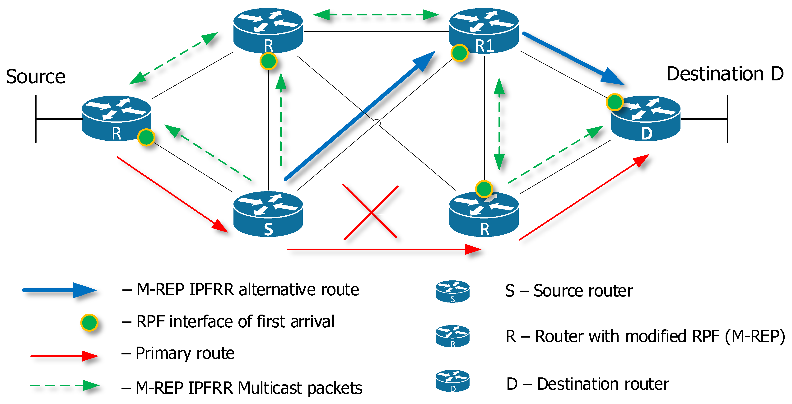
The PIM-DM is characterized by its specific flooding behavior, which is performed at the beginning of the multicast transmission and subsequent periodic intervals. M-REP uses this specific behavior to flood FRR traffic around the failed element in the network. The M-REP mechanism of the source router S, upon failure detection, encapsulates the unicast protected traffic to the multicast traffic characterized by the specific (S, G) multicast pair and floods it around the failed segment toward the router D (Figure 3).
To make it work properly and to be able to build a multicast distribution tree, the M-REP proposes the modification of the PIM-DM Reverse Path Forwarding (RPF) check. Using the modification, each M-REP enabled router creates RPF interfaces of the first arrival and the M-REP backup path is created as follows: S–R1–D. Destination router D removes the added M-REP multicast header and restores communication to the original state.
2.3. Problem Areas
If we look at the issue of FRR mechanisms, research from recent years, including ours, identifies some problem areas that arise from the characteristics of recently developed FRR mechanisms. Table 1 provides a brief summarization and comparison of these FRR solutions. Due to lack of space, in the following subsection, we will mention just three of them, which we deem the most interesting and critical.
2.4. Full Repair Coverage with Multiple Failures Support
Repair Coverage is the term that describes the efficiency of IP Fast Reroute mechanisms. If a particular IP Fast Reroute mechanism can repair all possible network failures, this means that the mechanism provides 100% repair coverage. The repair coverage is usually used to refer to the testing scenarios with only one failure.
If the FRR mechanism uses only metrics to calculate an alternative FRR next-hop router, it cannot provide 100% repair coverage. Provider topologies are diverse, and there may be situations where line metrics do not meet the requirements of a specific FRR mechanism to calculate a new next-hop router [60,61].
2.5. Cost-Based Calculations
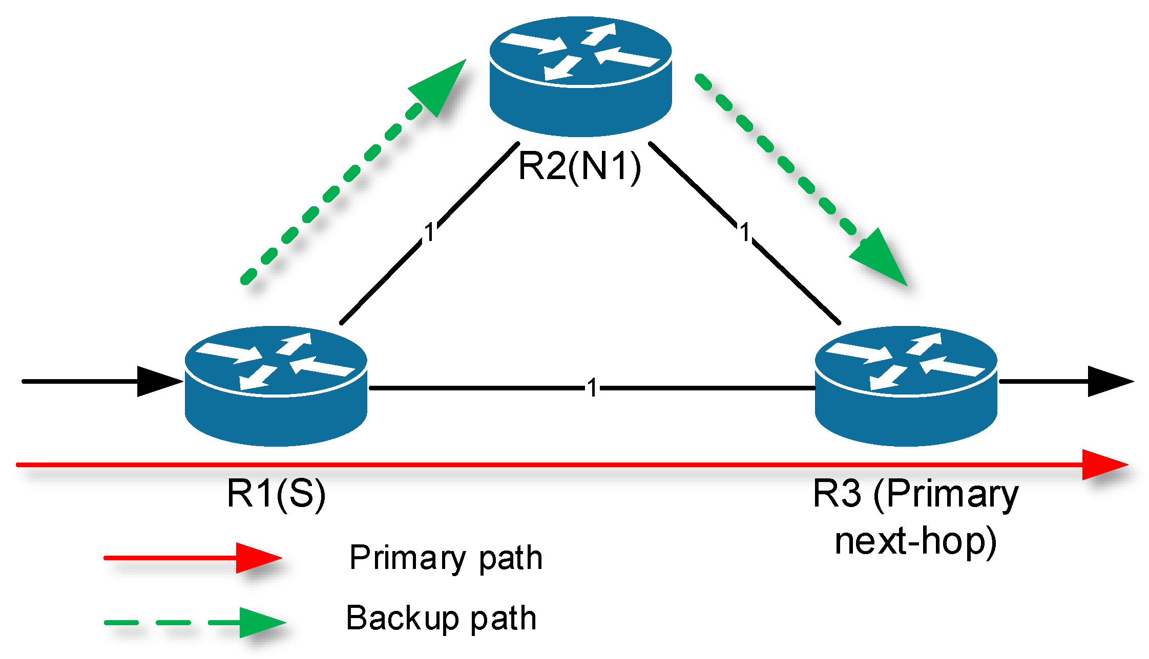
The majority of existing IP Fast Reroute mechanisms, such as the LFA [59] and R-LFA [29], calculate the backup path based on the cost of link metrics. There are several publications related to routing algebra [67,68,69]. However, in some circumstances, these FRR solutions are unable to calculate alternative next-hop routers. Figure 4 shows an example of a topology where the LFA mechanism can select the loop-free next-hop router N1.
However, if the link metric between routers R2 and R3 changes from 1 to 10, the conditions used in the LFA mechanism leads to a situation where the LFA will not be able to calculate the correct loop-free next-hop. Therefore, it is demanding to design such FRR mechanisms that are capable of selecting a backup path even in situations that have incorrect or unsuitable metrics [58].
2.6. Per-Prefix Calculation
The original B-REP mechanism was designed to protect only a few critical flows. This feature dramatically limited the use of the B-REP mechanism. Therefore, we have focused our efforts on improving the original B-REP mechanism so that we can provide the maximum possible protection for all faults affected by the fault. This behavior is called the per-prefix calculation in the IP Fast Reroute domain [70].
2.7. Research Goal (Research Aims and Objectives)
Based on the abovementioned facts resulting from the analysis performed in the last years of our focus on FRR, we consider it important to focus our research on the development of such FRR solutions that would provide an answer to these three areas.
Therefore, our goal was to develop an FRR mechanism that works with link metrics but also allows the construction of alternative paths independently of them, can handle multiple network failures, and, if possible, uses standardized approaches, for example for multi-hop tunneling solutions. The result of our research is the removal of significant limitations of the B-REP mechanism. This has led to the incorporation of completely new extensions and the emergence of the EB-REP mechanism, which in our view, meets the critical identified requirements for a modern FRR mechanism.
3. The B-REP Mechanism
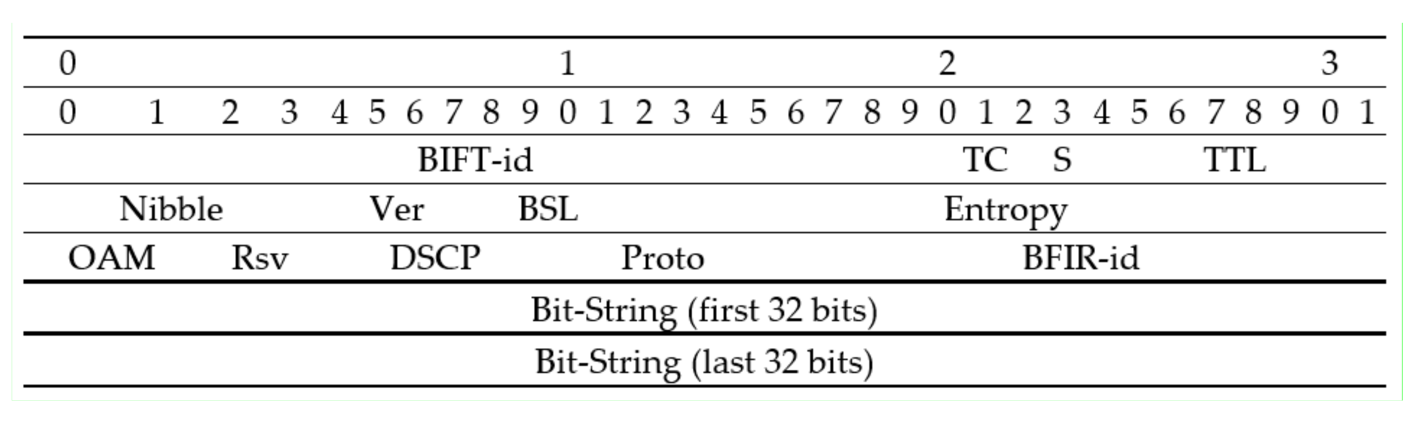
This paper deals with the design of new extensions overcoming the limitations of the original B-REP algorithm [39]. However, before we address them, we will describe key features of the original B-REP algorithm. The B-REP algorithm is a kind of proactive FRR mechanism that uses encapsulation (tunneling) techniques. Some existing FRR solutions use various proprietary solutions to define an alternative route. Unlike these, we have proposed that the B-REP uses a standardized header. The B-REP (and its successor EB-REP) for tunneling purposes therefore uses the standardized Bit Index Explicit Replication (BIER) header [71,72] (Figure 5).
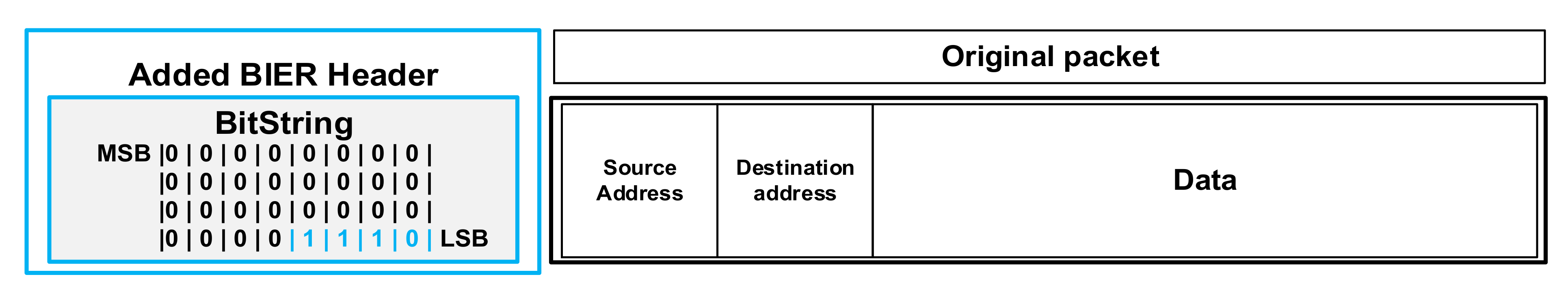
We suggest using a BIER header, among other things, that contains a special field called the Bit-String (BS) (Figure 6). The Bit-String is an array of bits, in which each bit indicates exactly one specific router in the BIER domain [73,74].
The BS field allows the B-REP algorithm to efficiently carry an alternative path. This alternative path is the result of a precalculation of the backup route performed by the Dijkstra algorithm. The backup route is calculated in the case of failure of the protected link and the specific flow routed above it. Thanks to the use of the BS field, the B-REP can efficiently and accurately specify the entire alternative path as the BS value. The BS value consists of the B-REP router identifiers (B-REP R-ID) of each router on the path.
The idea behind the B-REP design was the need to protect important customer flows carried via an ISP network. The B-REP FRR protects against link or node errors, but the Reroute calculation of protected interface redirection is based only on the predefined destination IP address (or a few of them). The address must be exactly specified by an administrator. The original B-REP does not support calculations in a wide range of all error-affected prefixes.
In addition to the BS field, the B-REP uses two specific tables for its operation. The first table is named the B-REP Table (B-REP T), and the second table is called the B-REP Backup Table (B-REP BT).
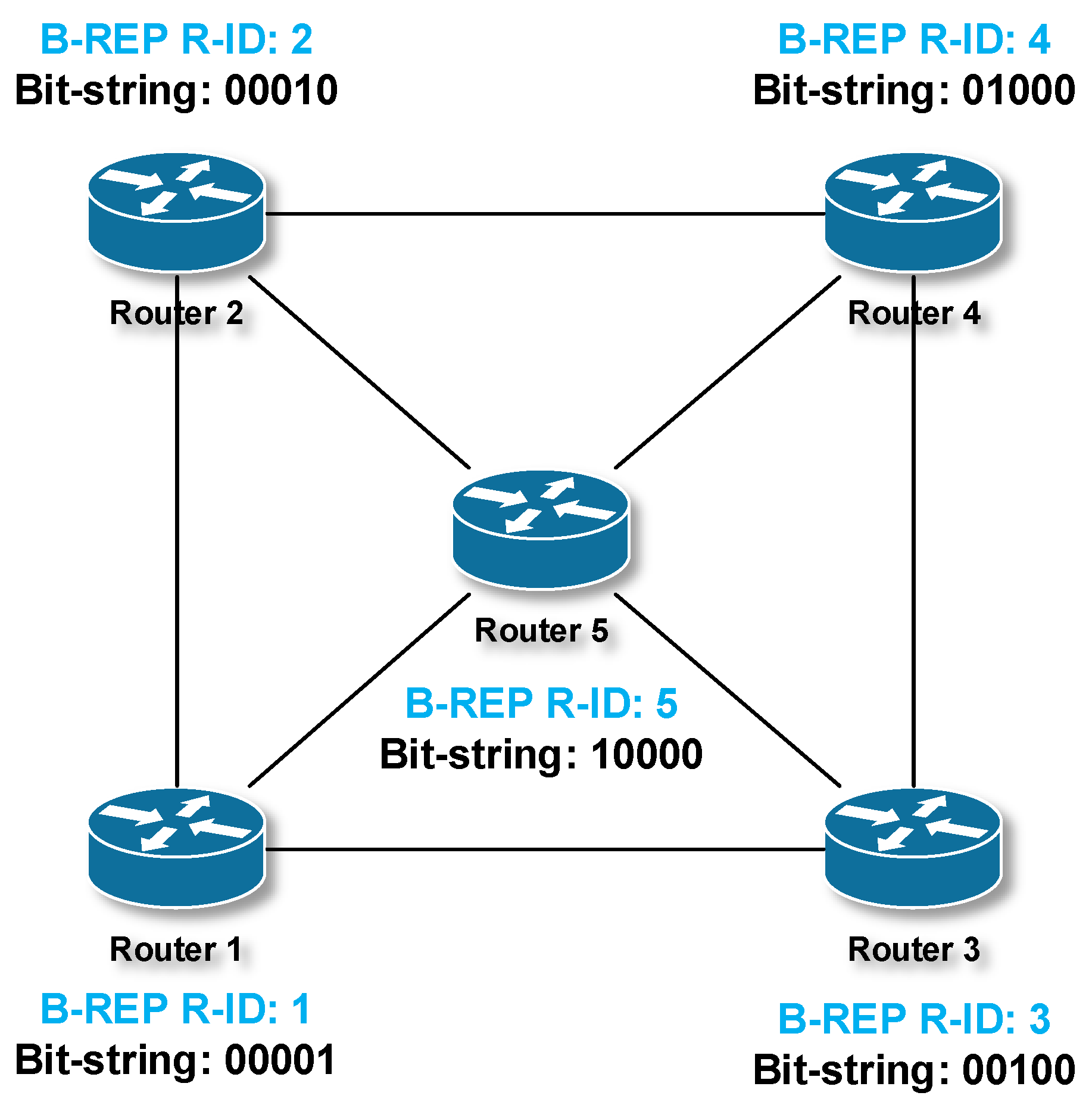
The B-REP table is initialized and is filled by the B-REP process first. The B-REP table maintains a list of all routers in the area, their B-REP router identifiers (B-REP R-IDs), and the corresponding Bit-String values (Figure 7, Table 2). Two of the values contained in the B-REP table are necessary parameters required for the correct operation of B-REP. The B-REP algorithm requires that each B-REP router must be uniquely identified within the B-REP protection domain. This unique identity of each B-REP router in the area is maintained in the B-REP R-ID. The second parameter is the corresponding Bit-String bit position of each router, which is used to generate the BS values. The BS position is derived from the B-REP R-ID. The B-REP table is created on each B-REP capable router during the algorithm initialization phase independently. The initialization of the B-REP T must end on all routers in the same way. Therefore, for the purpose of the B-REP R-ID assignment process, we assume either manual or dynamic assignment. Manual mode presupposes administrator intervention. Dynamic mode assumes the derivation of a B-REP R-ID from another unique identifier already used by routers. If B-REP routers use some type of Link-State (LS) unicast routing protocol, this mode is the preferred option; the reason being that LS unicast routing protocols, according to their nature, use the Link State Database (LSDB). The LSDB is the same on all routers. The LSDB contains complete topology information about all routers in the network and assumes the use of an ID as a unique identifier of the vertices of the network graph representation constructed by the LS protocol.
For the sake of clarity and the OSPF protocol used, we assume the following example of B-REP R-ID assignment process. First, the B-REP mechanism reads the OSPF LSDB and loads OSPF router IDs. Then, B-REP ranks all routers in the OSPF routing domain according to their OSPF Routers IDs in ascending order (Figure 7) and starts to assign B-REP R-IDs. The router with the lowest OSPF router ID obtains the first B-REP Router ID (B-REP R-ID = 1). This R-ID will also indicate the first position of the router in the Bit-String value. The router with the highest OSPF router ID will obtain the highest B-REP R-ID. In a network consisting of fifteen routers, the highest B-REP R-ID will be 15.
For a topology consisting of five routers, as is shown in Figure 7, the final assignment of the B-REP R-IDs and BS mapping may look like the data presented in Table 2.
After the initiation, the B-REP algorithm proceeds as follows: The algorithm for each of the preconfigured IP addresses and protected interfaces will construct the B-REP Backup Table (B-REP BT). The entry of B-REP table contains the identity of the protected interface; the B-REP R-ID of a destination router (D router), which decapsulates tunneled packets; and the Bit-String value, which exactly specifies the entire backup route from the router (S router) to the destination router.
B-REP BT is calculated in the following way: Each B-REP enabled router for each protected interface (metric set to infinity) and specified IP address of a protected flow specifies the destination router D. The D router is selected by using Dijkstra’s algorithm.
B-REP then calculates the backup path towards this router using Dijkstra’s algorithm and the local LSDB. Thanks to the use of the LS routing protocol in the backend, the B-REP algorithm is topology-aware. Finally, the B-REP sets the Bit-String value of the backup path. This BS value represents the list of BIER routers traversed from the source S to the destination router D (Table 3) in a hop-by-hop manner. Table 2 shows an example of how the precalculated B-REP Backup paths of the topology example are expressed using BS values.
The backup route is used in the case of protected interface failure. This means that if the router detects a link failure or a neighboring router connected through a protected link becomes unavailable, the router will start using the IP FRR mechanism and its pre-prepared backup plan. The B-REP algorithm starts encapsulating original IP packets using the BIER header. In the header’s BS field, the router writes the prepared correct BS value that represents the alternative route from a router that detects the problem (called as S router) towards the D router. By BIER encapsulation and correct BS value, the original packets are virtually tunneled around the failed element.
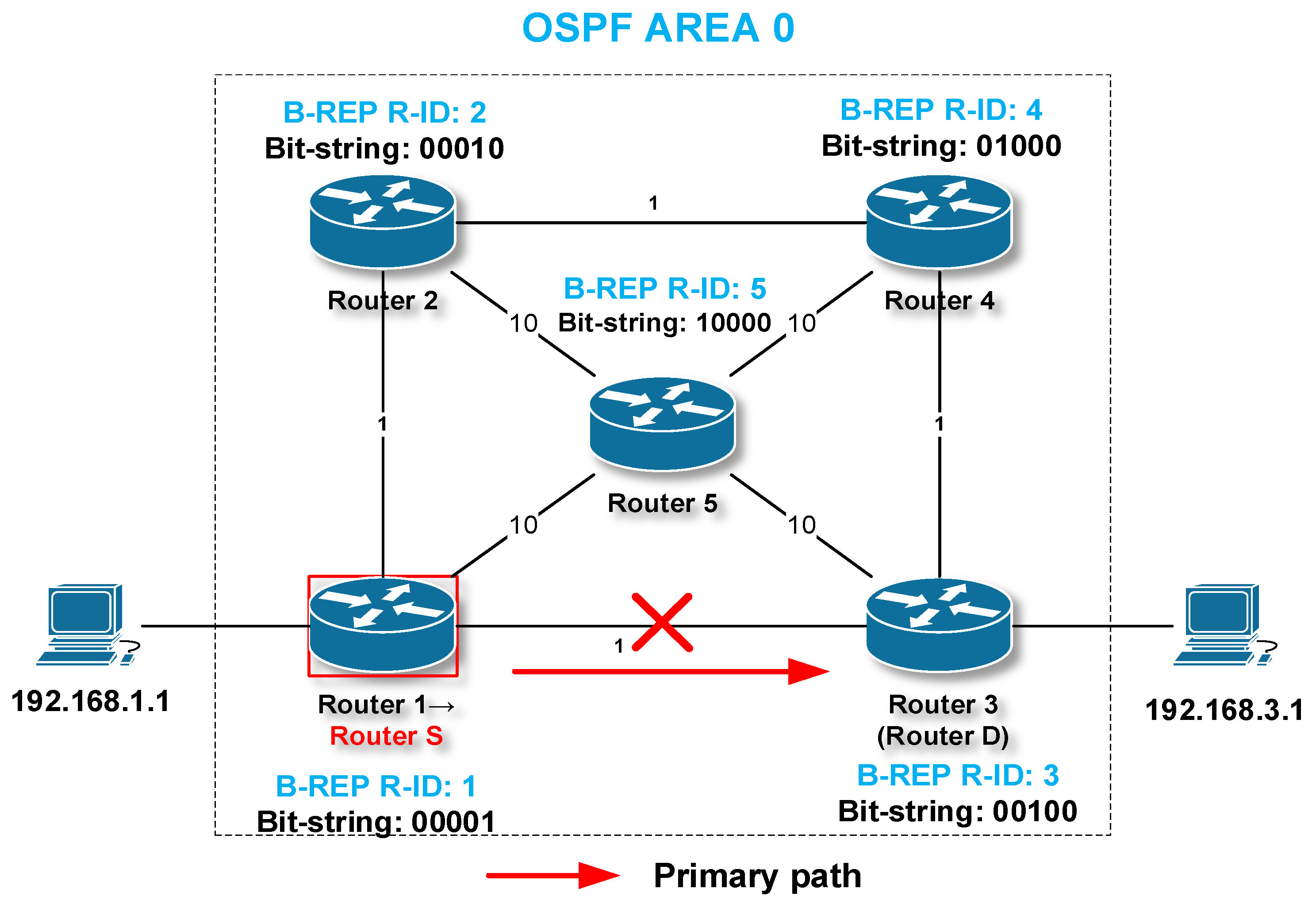
Let us briefly explain the elementary principles of B-REP FRR on a more illustrative example of the topology shown in Figure 8. We have already used the topology to illustrate examples of B-REP tables. Assume that the link between R1/R3 has failed and the protected flow directed towards the destination is therefore affected. Router 1 detects the link failure and becomes the router S. Router S selects a given backup path from the B-REP BP table based on the identity of the failed interface and the specific IP address of the protected flow. The S router encapsulates the packet of the original flow with a new BIER header and inserts the corresponding BS value into the BS field. The BS value of 01110 specifies a route via R2, R4, and R3. Based on the BS values, R1 sends a BIER packet towards the next-hop of a new alternative route, router number 2.
The next-hop router, i.e., router 2 (router R), receives the B-REP packet. As it is a BIER packet, it does not use traditional IP routing. Instead, it analyses the BS and selects the next-hop based on the BS bits (R4). R2 then sets its own bit of the BS value to 0. This indicates that the R2 router has successfully processed the B-REP packet. R2 then forwards the packet to R4. R4 repeats these steps and switches the packet to R3. Finally, the D router R3 receives the B-REP packet. R3 detects that the BS already has only one bit set to 1 and that this bit corresponds to itself. This fact indicates that router 3 is the destination of this B-REP packet. R3 is router D, the last B-REP router of the alternative B-REP route, where the B-REP FRR processing also ends. Therefore, R3 completely removes the BIER header and restores the packet to its original state. R3 routes the packet to its destination using a native unicast routing process. Router S can deactivate the B-REP mechanism in several ways. After the routing protocol convergence process is completed, or after the expiration of the special timer.
The B-REP is the result of research focused on the protection of critical IP flows, i.e., flows of special significance, purpose, or priorities. Therefore, the B-REP IP FRR mechanism aims at the FRR protection of the limited number of specific IP flows and has been designed and tested to protect against a single network failure. The B-REP solves this well. However, such a property may, under certain conditions, be considered as a limitation of the mechanism, for example in situations where multiple failures occur. Another limitation of the B-REP is its granularity. The B-REP protects only a few selected important flows. These are the main drivers that have led our research to define a more flexible and modern IP FRR mechanism. The output is the Enhanced B-REP, which addresses the abovementioned B-REP limitations and offers multi-failure protection for all network flows.
4. The Proposal of the Enhanced B-REP Mechanism
The B-REP mechanism, which was described in more detail in the previous chapter, was considered in terms of deployment for networks with lower expected throughput. Therefore, we focused on the ability to protect only a few, yet critical, flows from the failure of the protected interface. The simulations confirmed the functionality of this concept. Therefore, we focused on finding a more general approach, with the design of B-REP properties that protect against one or more errors, but for all affected flows. The concept will, of course, still support the original functionalities. However, with the new features, it will also be suitable for more complex networks or networks with higher throughput. Lack of protection against multiple network outages is a weakness of most of the FRR mechanisms analyzed.
In this chapter, we present a significant improvement of the B-REP mechanism. For differentiation, we call the enhanced version Enhanced B-REP (EB-REP), with an impact on all tables used. EB-REP enhances the original design to support protection against multiple network outages with FRR calculations for each protected interface, and thus for all network prefixes affected by the failure.
EB-REP will work as follows: At the end of a router boot process (or after the EB-REP initial configuration), the EB-REP mechanism must wait for the unicast routing process to complete, i.e., the end of network routing convergence. Then, the EB-REP process initializes the EB-REP table (EB-REP T). This means that EB-REP must assign a unique EB-REP ID and a corresponding Bit-String position value to each router within the EB-REP protection domain. The EB-REP protection domain is a continuous area of EB-REP enabled routers. The table initialization process is identical to the B-REP one. At the end of the process, each EB-REP enabled router has populated an identical local EB-REP table (Table 4).
Subsequently, each router must prepare an EB-REP backup table (EB-REP BT), which is the main working database of the EB-REP algorithm. To perform this, the EB-REP process first obtains a list of protected interfaces (given by the EB-REP configuration). The EB-REP FRR protection can be enabled on some as well as all interfaces of an EB-REP enabled router. The EB-REP then retrieves from the unicast routing table all network IP addresses that the router uses to route individual packets over protected interfaces.
As a next step, the EB-REP will start calculating alternative paths for each identified network IP address (network prefix), which will be used in case of protected link failure. Like B-REP, EB-REP uses the Dijkstra algorithm to calculate an alternative path. The Dijkstra algorithm accurately determines the list of passing routers from a given local router to the egress router of the EB-REP domain (D router) closest to the given destination network IP address. EB-REP identifies routers of the path from the unique Bit-String value of the alternative path. Finally, all this information is written in the EB-REP BT (Table 5). One EB-REP BT entry consists of the output interface used to route the packet of an affected flow, the IP address of the flow itself, and finally, the BS value of the alternative path.
Here is the first difference and improvement over the legacy B-REP process. Once the EB-REP FRR is enabled on all interfaces and the EB-REP BT is calculated, the EB-REP mechanism provides FRR protection for all IP addresses affected by a network error (protected interface or neighbor).
This approach also has its disadvantages. Per-prefix protection calculates one alternative backup path for each network prefix. Therefore, each prefix will have one best-metric backup path calculated. The problem with this method is the high overhead on the CPU and memory.
The process of EB-REP tables initialization is performed for the first time as the EB-REP mechanism is initialized and then each time after each routing convergence ends or EB-REP configuration is done. After EB-REP tables’ initialization, the EB-REP process stays in the monitoring mode.
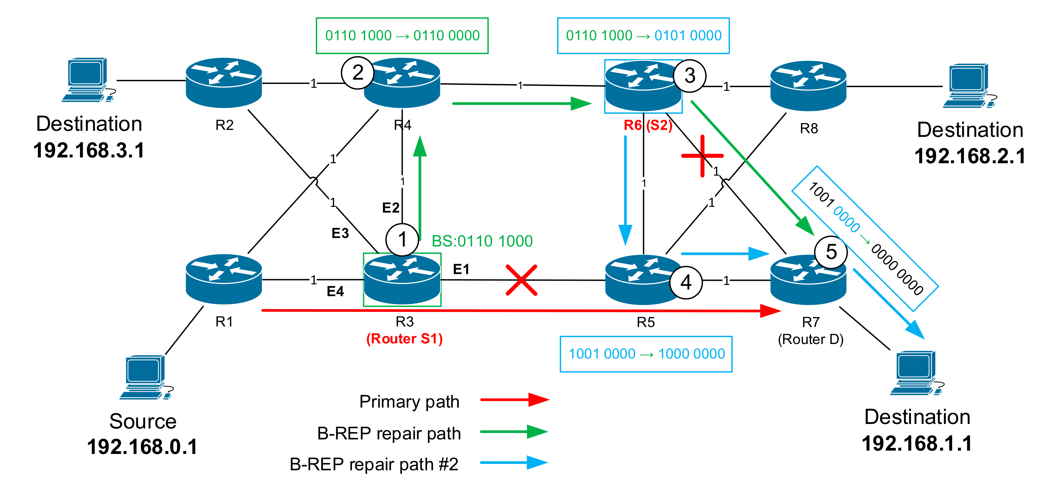
In the case of a network error, either failure of a protected interface (interface state changed to down/down on ISO OSI layer 1 (L1) or (L2) or neighbor unavailability (using BFD protocol detection), EB-REP proceeds as follows, as in the example shown in Figure 9. Suppose we have eight routers and a packet flow routed over the network between a source (with an IP address of 192.168.0.1) toward a destination (identified by an IP address of 192.168.1.1). The shortest primary path used to route packets is through R1 → R3 → R5 → R7.
The router that detects the first failure becomes the source router S. The S router starts the routing protocol convergence process and uses the EB-REP FRR protection mechanism until it obtains new updated routing information. The EB-REP mechanism uses the encapsulation of the original IP packet with an additional BIER header (EB-REP header). The EB-REP header contains the correct alternative route specification stored in the Bit-String header field. To obtain the BS value, router S searches in the EB-REP BT for the affected destination IP address and the identity of the failed protected interface. Router S reads a given Bit-String value of the backup path, encapsulates the packet, and sends it out through an active interface to the precalculated next-hop EB-REP node (router N).
The N router is neither a source nor a destination; it is a router along the way. The N router receives a packet with the BIER header and checks whether the BS value has more than one bit set. Router N then adjusts its bit in the BS (meaning that the packet has been processed) and forwards the EB-REP packet towards the next-hop according to the BS value.
In our situation, it is the R3 router that has detected the unavailability of its E1 interface and faces the problem of how to route packets towards the destination 192.168.1.1. R3 becomes the router S. R3 searches its local EB-REP BT to find the correct BS value of the alternative path for 192.168.1.1 and encapsulates the packet using the BIER header with the path BS value of “… 0110 1000” (Figure 9). Finally, R3 routes the EB-REP BIER packet to the EB-REP next-hop, here R4. R4, as the N router, processes the packet, sets R4′s bit in the BS value to zero, and routes the packet according to the BS value to another directly connected next-hop router, R6.
The second improvement of the EB-REP mechanism is the protection against multiple network failures. The router R6, like another router N, will normally repeat what R4 did: sets its associated bit in the BitString to zero and checks BS for another next-hop, which is R7, and forwards the EB-REP packet.
However, if another failure occurs on the backup path, the EB-REP will react differently. Once the router control plane detects and reports the connectivity failure, the new reroute process must start. The N router becomes a new S router (to differentiate it, let us call it S2). The EB-REP mechanism on the S2 router first reads the destination IP address inside of the packet IP header. Then, the router S2 looks inside its EB-REP Backup Table and selects its precalculated BS value according to the destination address of the original packet. This BS value is then inserted as a new BS value into the EB-REP packet header.
In principle, there are two cases where, in addition to our first, other failures can occur. The first case is when there is another outage in another part of the network and outside the currently used alternative EB-REP route. In this case, the EB-REP mechanism behaves the same as when a new error is detected (a router becomes the new S router). That is, the EB-REP finds a new precalculated Bit-String of an alternative path, creates an EB-REP packet, and inserts the BS value into the EB-REP header.
The second situation is that an existing alternative EB-REP route fails, which means that packets are already routed (switched) based on the BS value and not their destination IP address. In this case, the question is, can failure occur on the precalculated alternative path for D, where the router acts as R? The alternative path calculated by each router (including S1) is the second shortest possible path for D. That means that for other routers on this alternative path (including S2), an alternative path will be the shortest and primary for a specific D. Therefore, if there is a second outage on our main alternative path calculated from S1 to D, and the N router (new S2) detects a failure on the next-hop according to the Bit-String-based routing (decided by the S1), it is an outage on the primary unicast next-hop route to the destination from the S2 point of view. Therefore, S2 has already precalculated an alternative path to D. This alternative path from S2 will replace the alternative path from S1.
If we apply this behavior to our situation, router R6 detects an outage on its primary path toward D (R7), which is part of the alternative path decided by R3 (S). Therefore, R6 must reroute the EB-REP packet to an alternative next-hop. For this purpose, the R6 uses its precalculated EB-REP backup path and modifies the existing Bit-String with a value of “…0101 0000” and forwards the packet toward the new next-hop, router R5. R6 becomes the new router S (S2). This adjustment of Bit-String values ensures the process of multi-failure protection.
Finally, the EB-REP packet is routed through R5 and to destination D, router R7. R7, as the last router on the path, receives the EB-REP packet with a Bit-String value of “0100 0000”. After processing, the router sets the last bit in the Bit-String to zero, which means that all bits are now zero. This indicates to the EB-REP router that the decapsulation process needs to be performed. Therefore, the R7 router decapsulates the IP packet by removing the added BIER (EB-REP) header. Packets are then routed forward using unicast routing.
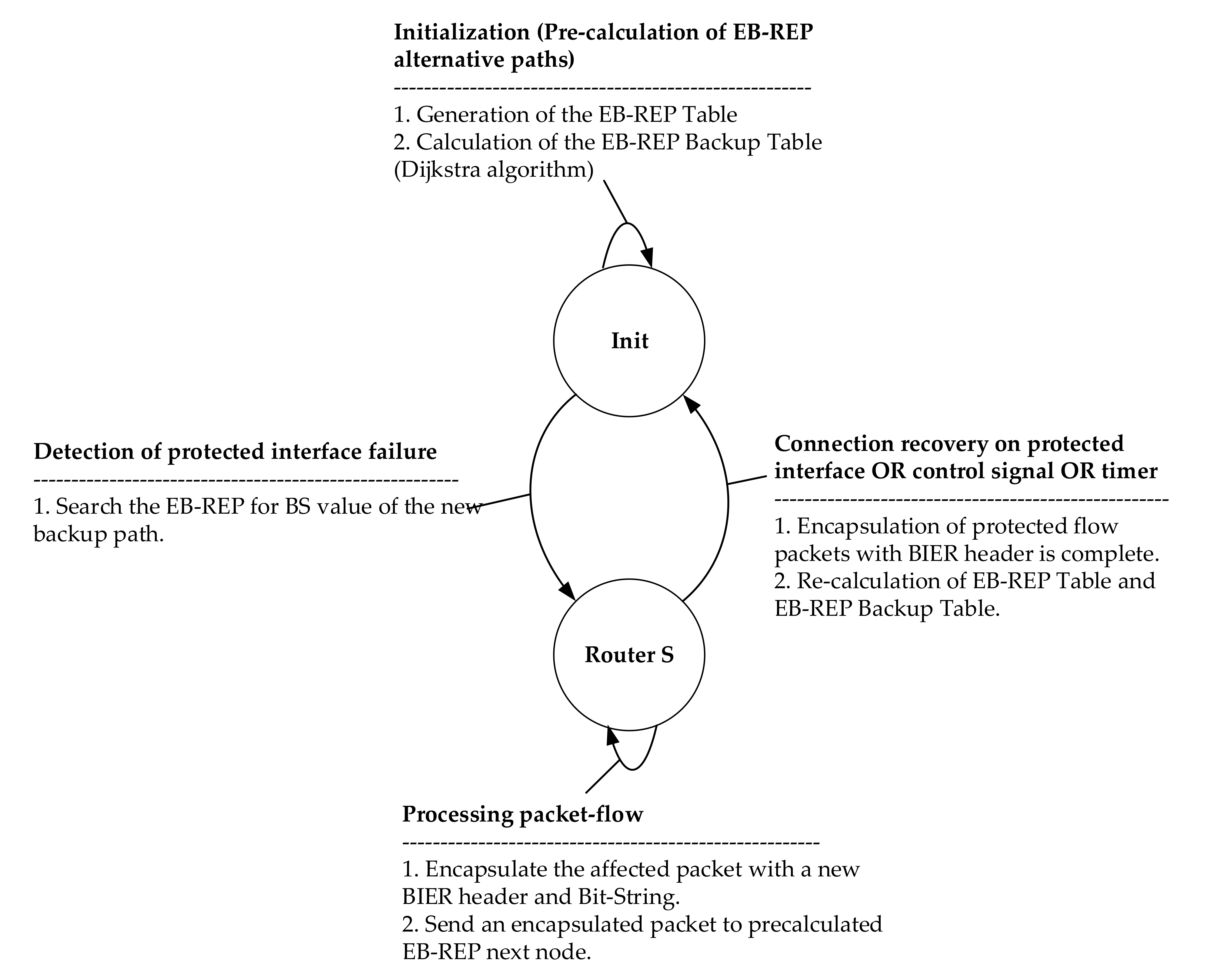
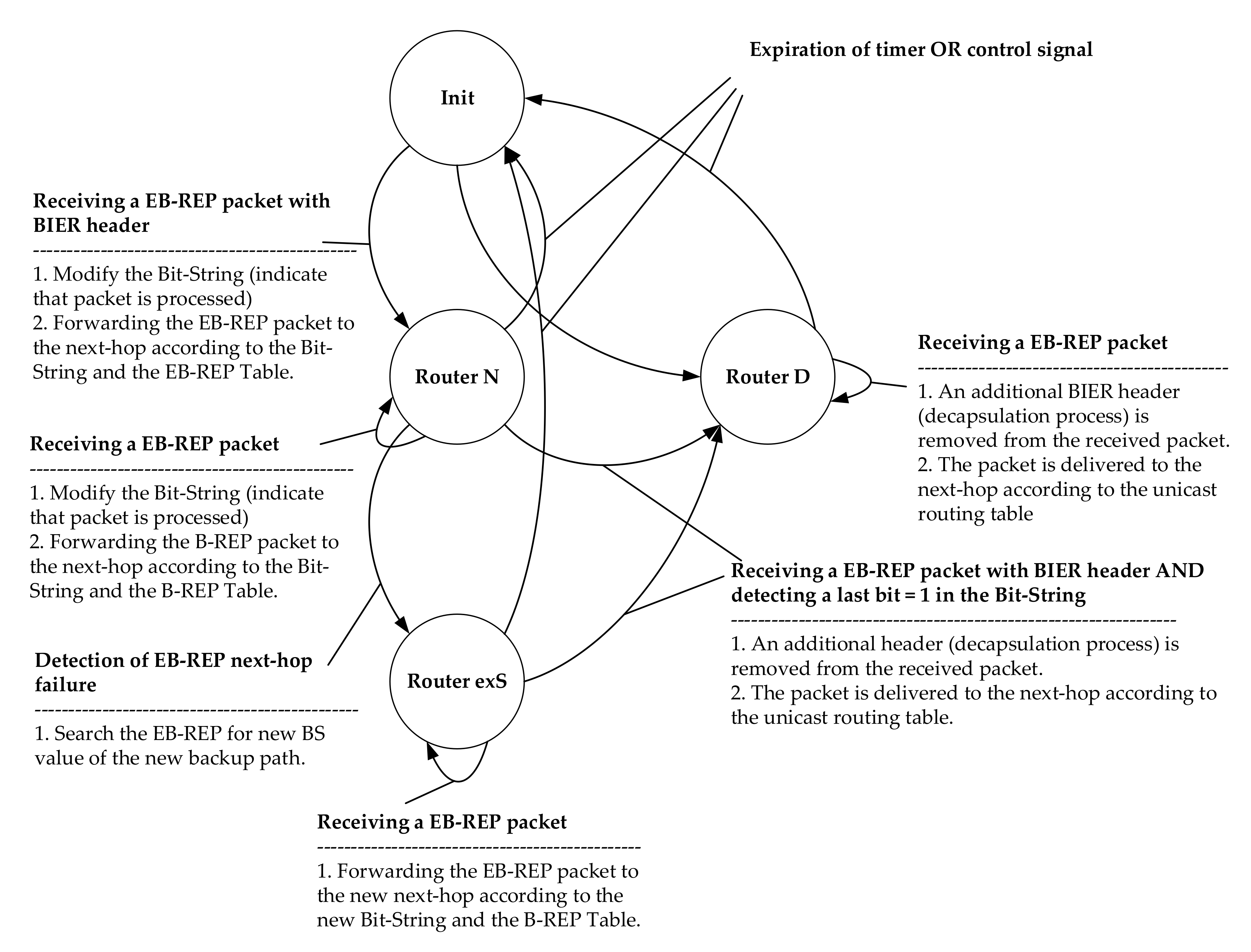
The EB-REP State Diagrams
To better understand the activities of the EB-REP mechanism, we created state diagrams of the activities of the respective routers. These are state diagrams describing the state and transient activities of the S router (Figure 10, Table 6), and as well as the D and N routers (Figure 11, Table 7). These three types of routers are involved in the EB-REP FRR process.
The EB-REP process of the mentioned routers can move between the states described in the following tables.
5. Evaluation of the Enhanced B-REP FRR Mechanism
In this chapter, we describe the verification process of the EB-REP FRR extension proposals described above. For this purpose, we used the discrete-event network simulator OMNeT++. OMNeT++ provides a very robust and feature-rich environment suitable for complex network simulations and experiments; however, it only supports static routing. Therefore, OMNeT++ has been extended using the INET extension framework library. INET provided us with the required dynamic routing behavior using the OSPF protocol and allowed us to program and test the EB-REP FRR functionalities.
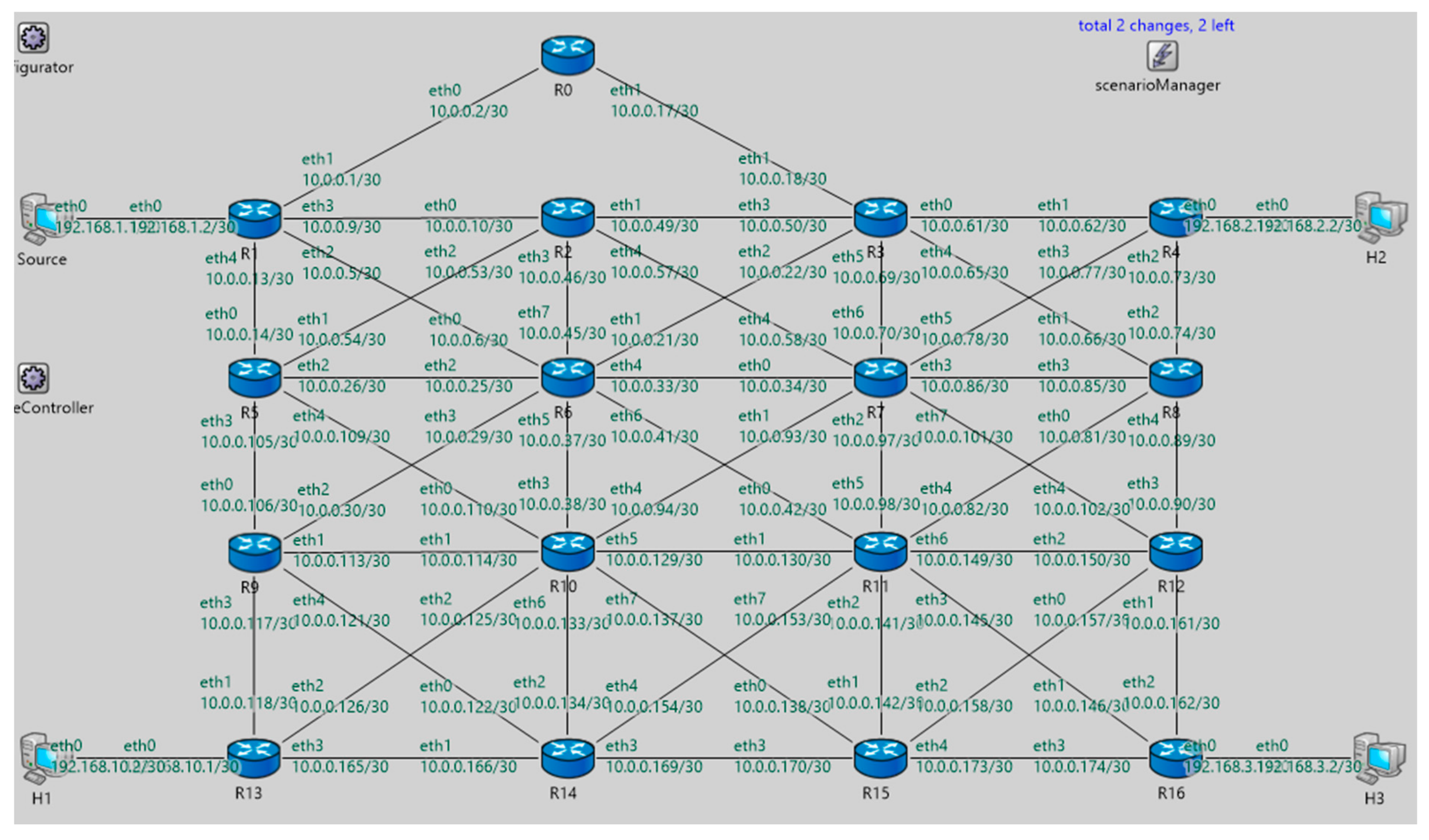
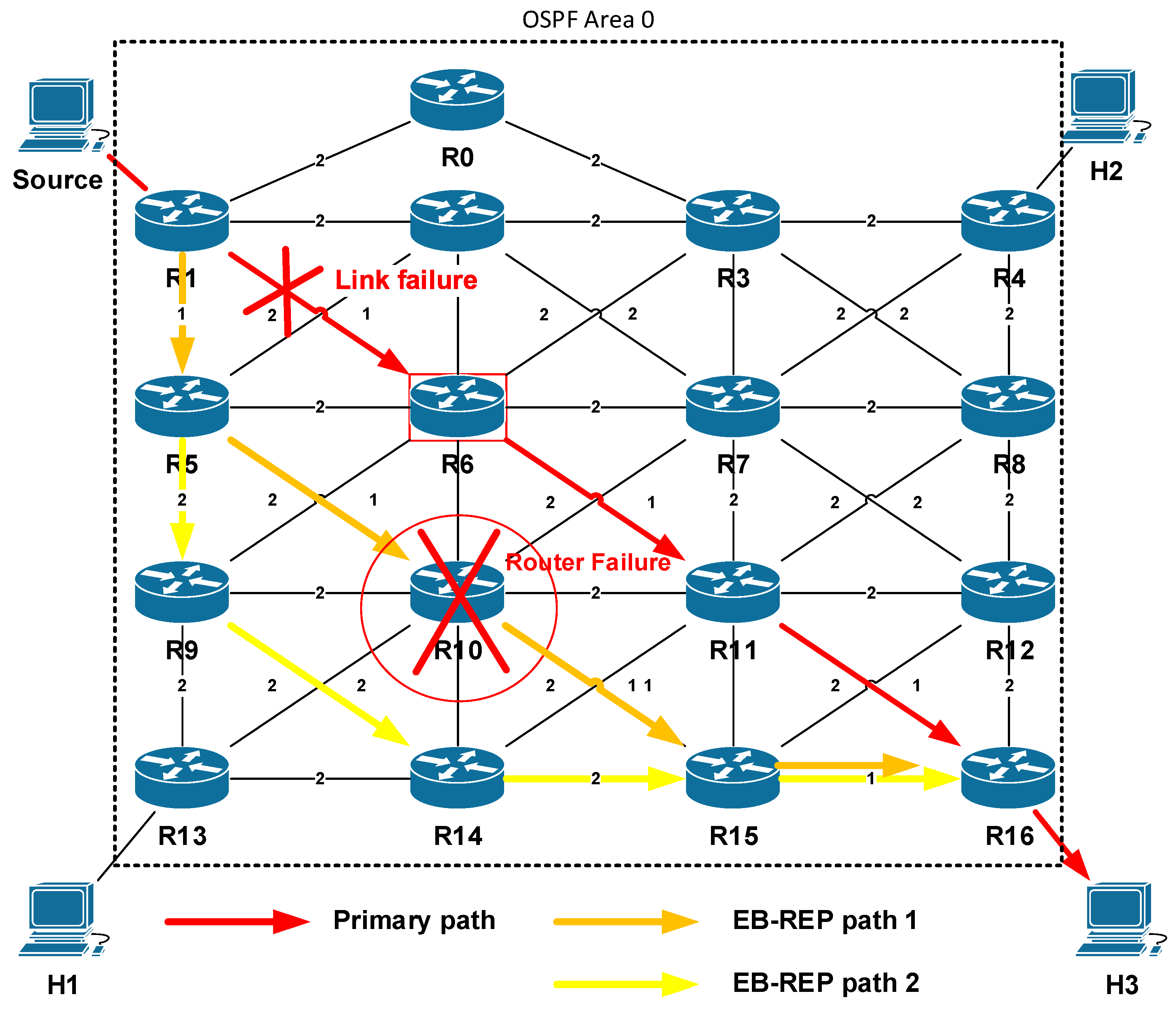
The EB-REP FRR proposal has been tested using several different network topologies consisting of several interconnected OMNeT++ routers (up to tens). Within these topologies, we then tested the EB-REP behavior in the event of one or multiple independent network failures. Performed simulations showed the correct behavior of the Enhanced B-REP algorithm, in which it was able to deliver all packets affected by failures. In this section, as an example of the evaluation process, we describe one of the comprehensive simulation scenarios. The topology consists of a 4 × 4 (+1) matrix of interconnected OMNeT++ routers and four end-point devices (Figure 12). For simulation purposes, the OSPF v2 protocol is used as the dynamic IP routing protocol. Routers are interconnected by several links with the link metrics as is shown in Figure 13. Traffic is sent from the source station to the destination, which is the H3.
Within the simulated topology, we have then simulated two network failures. The first simulated problem is the link failure between routers R1–R6. The second simulated error is a node failure, where a router on the alternate path stopped working. The complete overview of the simulated scenario is in Table 8.
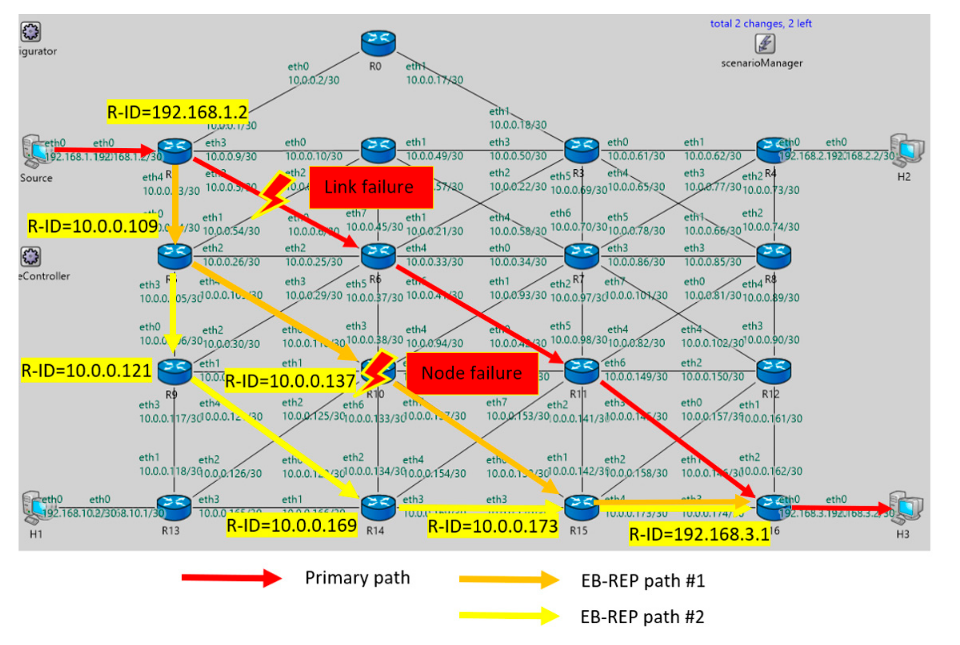
The exact description of the scenario is as follows: At the beginning of the simulation process, we set a waiting period of 50 simulation seconds (sims) to give the OSPF routing protocol time to complete the convergence process. Subsequently, at the time of 64 sims, the Source host (top left, Figure 14) starts generating a simple User Data protocol (UDP) data flow for host H3. Based on the selected topology and cost evaluation of connected links, the OSPF selects the path through routers R1–R6–R11–R16 as the primary delivery path (Figure 14, red arrows). Then, 70 sims after the start of the simulation, we simulate the first connection failure between routers R1–R6. R1 becomes the EB-REP S router, and it will use the precalculated alternate path through R5–R10–R15–R16 to bypass the gap (Figure 14, orange arrows). At the time of 80 sims, we simulate the second failure as an R10 router fault. The problem, in this case, occurs on the alternative route and router R5 becomes the second router S (exS), where it reroutes packets over a new alternative path, R9–R14–R15–R16 (Figure 14, yellow arrows).
Let us take a closer look at what happened during the simulation. Upon completion of the OSPF convergence process, as indicated by the timer in the simulation, the initialization of the EB-REP process begins on each router. Their EB-REP processes enter the Init state. In other words, routers from their OSPF LSDBs populate the EB-REP table and EB-REP backup tables for protected interfaces. It should be noted that the EB-REP table is calculated by sorting all area routers in ascending order according to OSPF R-ID. After this process, B-REP IDs and corresponding Bit-String positions are assigned the same way, as we can see for router R1 in Table 9. The EB-REP tables are the same at the end on all routers within the domain.
As a next step of the EB-REP initiation, each router calculates its EB-REP Backup Tables. The EB-REP now supports protection for all flows (all destination IPs) and all interfaces of a router. These features were also enabled in the simulation, and each router had all its interfaces enabled as a protected interface. In the real world, this step can take a while in a situation where the EB-REP is enabled on all interfaces and can lead to larger EB-REP tables. Therefore, in real deployment situations, we expect that it will be possible to manually edit and delete the interface list, or if necessary, to define a list of IP addresses of protected flows. A fragment of the EB-REP BT table from router R1 is shown in Table 10.
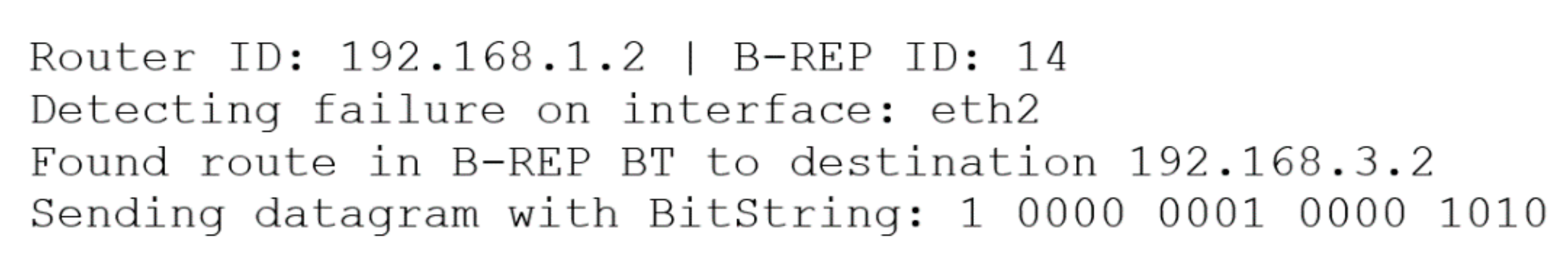
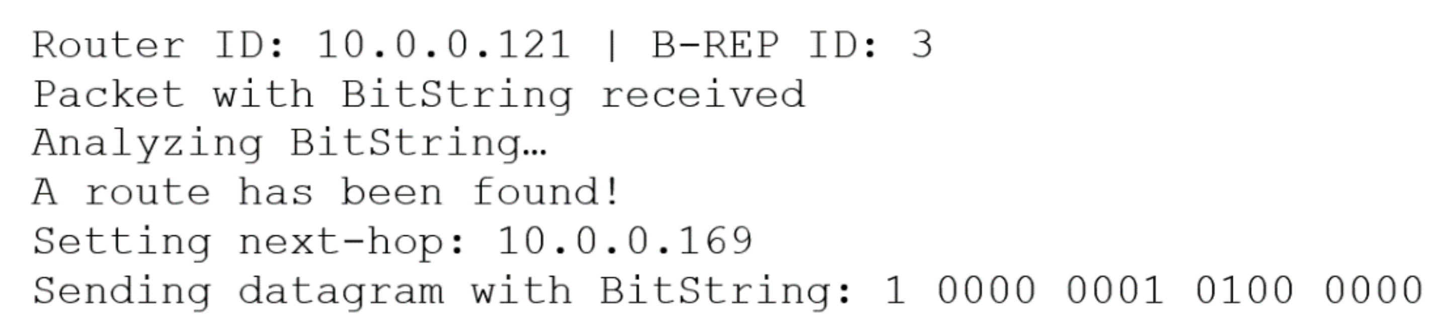
According to the present scenario, the first failure is a link failure between R1 and R6. In this case, the Eth2 output interface of the R1 router goes down and the routing to the host H3 is no longer possible. Upon detection of a failure and upon receiving the packet for 192.168.3.2, R1 becomes the S router and its EB-REP mechanism looks through the EB-REP BT table for the Eth2 output interface and the destination IP address. Once it finds the correct table entry, the router reads the corresponding Bit-String value of the alternate route, here 1 0000 0001 0000 1010 (LSB). This BS value defines an alternative path from router S to H3 as the route via R5–R10–R15–R16. R1 then immediately encapsulates the original IP packet with a new EB-REP BIER header, inserts the BS value, and forwards the packet to the R5 next-hop. This behavior is shown by the output from the OMNeT++ simulator console illustrated in Figure 15.
The EB-REP packet equipped with a BIER header and a corresponding Bit-String receives R5. From the point of view of EB-REP processing, R5 becomes the router R. R5 processes the EB-REP packet as described above and forwards it further. The packet thus passes through a precisely determined path defined in its BS field from router to router, up to router R16. R16, in terms of EB-REP, it is the router D, which detects it is the last router of the alternative path. R16 decapsulates the IP packet (removes the BIER header) and forwards it successfully to H3.
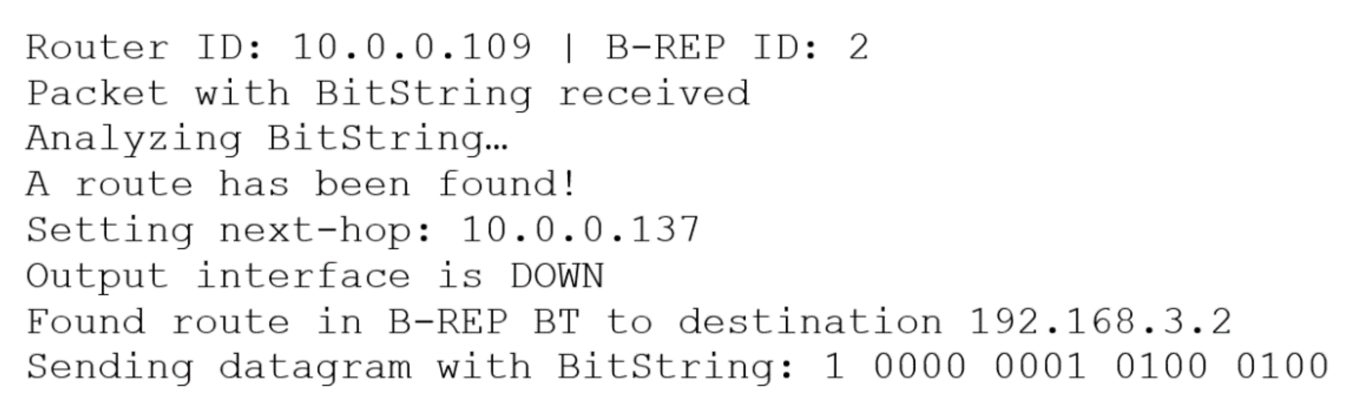
At the time 80 sims, R10 fails, which is detected by its neighbor on an alternative path, the R5 router. Therefore, when R5 receives another EB-REP packet with an inaccurate Bit-String value specified by R1 (the route over R5–R10–R15–R16). R5 analyses the Bit-String and it knows that R10 is dead, and so it must respond. Therefore, R5 becomes the new S (exS). R5 examines its EB-REP BT table and finds a new alternative route for the selected destination (192.168.3.2). The result from this process is the new route via R9–R14–R15–R16 specified by a new Bit-String = 1 0000 0001 0100 0100, and with a new next-hop (R9). As the next step, R5 replaces the old Bit-String value with a new one and reroutes the packet towards the next-hop R9 with EB-REP ID = 3 (Figure 16).
It is important to note that this redirection process (failure detection on the already repaired path) is a new feature of the EB-REP mechanism. R9 receives the EB-REP packet and processes it as the router R; i.e., R9 analyses the BS, selects a new next-hop, and sets its bit in the packet’s Bit-String to zero (Figure 17). This marking ensures that the packet has been processed on the router, thus preventing the formation of a loop between routers. Finally, according to the carried Bit-String (1 0000 0001 0100 0100), R9 looks for a directly connected EB-REP next-hop and forwards the packet to the R14 next-hop.
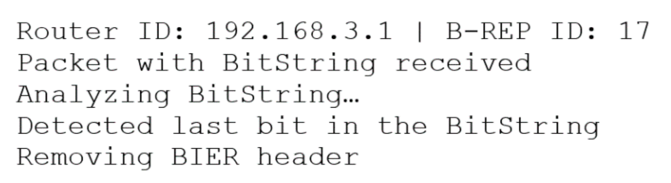
The packet is now routed and delivered through R14 and R15 to R16. R14 and R15 use the same EB-REP processing as R9. However, the situation at R16 is different. R16 receives the EB-REP packet with the Bit-String value of 1 0000 0000 0000 0000. The last bit in the Bit-String, which is also the bit set to position R16, indicates that R16 is the target (or destination) of the rerouting process. R16 therefore removes the EB-REP BIER header and decapsulates the packet (Figure 18).
This operation reverts the packet to its original form, and R16 routes the packet as classic unicast data via its unicast routing table. The packet is now forwarded to the destination. In Table 11, we may observe this behavior as the output from the OMNeT++ simulation console.
6. Discussion of the Obtained Results
The EB-REP FRR mechanism is an advanced version of the older B-REP mechanism. The main advantage of the EB-REP mechanism and an improvement over its predecessor B-REP is the support of protection against multiple failures and per-prefix-based calculation of alternative FRR backup paths. By supporting multiple-network failure protection, the EB-REP mechanism is more robust and flexible in situations of unexpected network error conditions. During the performed simulations, EB-REP was able to find correctly applied precalculated alternative routes, even in the case of multiple outages, and deliver all flow packets to the destination. Simulation results show that our IP FRR mechanism is both practical and feasible and can successfully provide network protection against multiple link or node failures in terms of agility, robustness, and efficiency.
Per-prefix backup path calculations are a feature that allows the algorithm to calculate the optimal backup path for all destinations and all device output interfaces. All its features make it a unique algorithm in its class of FRR mechanisms. However, as a member of the proactive category of FRR mechanisms, it also inherits some of their disadvantages, namely the need for preliminary calculations and increased consumption of system resources in the form of CPU and RAM, as well as network capacity, caused using tunneling. The main advantages and disadvantages are summarized in Table 12.
As with the original B-REP mechanism, the EB-REP mechanism also provides 100% repair coverage, which means the possibility to repair all link or node failures in the network for all possible destinations. We are aware that the computational costs for determining the correct paths for the individual destination addresses may be higher. EB-REP therefore allows the customization of its activity to define a list of protected interfaces or a list of critical prefixes for which the FRR service will be provided. The ability of EB-REP to define the FRR backup path manually, even if the metrics of links are inappropriate or unspecified, can be understood as an advantage to this functionality.
Like most existing IP Fast Reroute solutions, the EB-REP uses a precomputation system to calculate multi-hop backup paths in advance. For this purpose, the EB-REP uses link-state topology information collected by a link-state routing protocol. Our solution does not depend on the type of link-state protocol used, but for this paper and simulations, we used OSPF v2. A more comprehensive summary of the analyzed features of existing FRR solutions is provided in Table 13.
6.1. Speed Comparison of EB-REP and Existing FRR Mechanisms
Comparing the speed of EB-REP to alternative FRR solutions, it is necessary to describe the FRR procedure in more detail.
6.1.1. Theoretical Comparison
The FRR process begins with fast failure detections, especially using the BFD protocol and its hello message system. The link is declared as broken if one side of the BFD session does not receive three subsequent BFD hello messages. It usually takes around 30 ms using a 10 ms BFD hello message interval. Upon detection of a failure, an FRR mechanism must change routing information for the use of a new backup path.
The switchover to the new backup path is in the order of milliseconds because the path is already precalculated by the EB-REP mechanism. From the theoretical view, we can state that the recovery rate provided by the EB-REP mechanism is comparable to other proactive FRR solutions.
6.1.2. Simulation Comparison
We also performed simulation testing for comparison of the proposed EB-REP against LFA, R-LFA, and EM-REP mechanisms. We focused on the comparison of rerouting time. In these simulations, we used our OMNeT++ implementation of the BFD protocol [75]. For comparison purposes, we used ten various topologies and results were averaged over eight simulation runs.
The BFD echo interval was set on R1 to 0.010 sims. The BFD protocol will declare the link as down in the case when three BFD responses have not arrived. When a specific node fails at time 50 sims, the BFD protocol running on R1 will then report this at time 50.031 sims. By receiving this system message, the FRR mechanism will be activated and will perform the rerouting process.
We measured the time from the occurrence of a node failure to the time when the source router sends rerouted data to an alternative next-hop; this means that we measured the detection time plus installation of FRR path plus forwarding time. The measured results of reroute process are shown in Table 14.
The results show that the rerouting process of a specific FRR mechanism depends mainly on the failure detection time (0.030 sims), and that the rerouting process time of a specific FRR mechanism is negligible. FRR alternative routes are calculated in advance, and therefore they are ready to install immediately. Installation of an FRR alternative path takes only a minimal part of the whole rerouting process.
According to obtained results from the OMNeT++ simulation, we could confirm the theoretical comparison that the EB-REP mechanism in terms of speed is comparable with these two FRR solutions.
6.2. Testing in Real Networks
Currently, only a few existing IP FRR solutions, such as Equal Cost Load Balancing and LFA, are integrated into real router operating systems (for example, Cisco IOS or Juniper JunOS). Therefore, the implementation of test setups to obtain some real measurements is complicated. Testing the new FRR mechanism using a suitable network simulator such as OMNeT++ or NS2 seems to be the most appropriate solution. We have decided to develop and test new FRR solutions in the OMNeT++ simulator, because of its reliability, good framework base, and large community. Currently, we have successfully implemented some of the existing FRR solutions, such as LFA and R-LFA, into the OMNeT++ simulator. Therefore, the evaluation of the EB-REP mechanism was performed in the OMNeT++ simulator and we used it to compare the EB-REP with other FRR solutions.
7. Conclusions
In this paper, we introduced a new enhanced version of the original B-REP FRR mechanism, called the Enhanced B-REP mechanism, which provides an advanced reroute solution for IP network infrastructure. The EB-REP mechanism eliminates two significant disadvantages of the B-REP mechanism, namely the provision of protection against only one network error (even link or node) and only for specific but critical IP flows. Proposed EB-REP functionalities currently support protection against multiple outages in a single network. This protection can now be provided for all network flows. Both functions make EB-REP an interesting contribution to solving the IP FRR problem.
We should also note that EB-REP inherits and retains several innovative properties of the B-REP mechanism. Let us mention the use of a standardized BIER header for packet tunneling and the usage of the header Bit-String field. This decision offers us the opportunity to use a standardized approach to tunneling user data and at the same time to transmit FRR information, within which the BS is a highly effective method of defining the entire multi-hop alternative route. Another benefit is routing by Bit-String, which creates unique and exact hop-by-hop switching between the router around the failed element in the network. Another advantage of using Bit-String is the ability to perform unique and accurate hop-by-hop packet processing, such as efficient switching. The speed of EB-REP is comparable to existing FRR solutions.
The EB-REP was implemented and tested in the OMNeT++ discrete event simulator with various scenarios and topologies. These tests validated the functional correctness of all EB-REP improvements. Our further research focuses on the application of EB-REP to other specific areas of deployment, such as the IP FRR managed through SDN and FRR protection in WSN. At present, we are focusing on the possibilities of implementing Fast Reroute technology into existing WSN protocols, such as Ad Hoc On-Demand Distance Vector (AODV) and Destination-Sequenced Distance-Vector Routing (DSDV). These protocols are implemented in the OMNeT++ tool and therefore are well suited to support further FRR investigation and FRR implementation intentions.
Author Contributions
Conceptualization, J.P. and P.S.; software, J.P.; validation, J.P. and P.S.; formal analysis, J.P., P.S., M.K.; investigation, J.P.; resources, J.P.; data curation, J.P.; writing—original draft preparation, J.P.; writing—review and editing, J.P., P.S., M.K.; investigation, J.P.; visualization, J.P. and P.S.; supervision, J.P. and P.S.; project administration, J.P. and P.S.; funding acquisition, J.P., P.S. and M.K. All authors have read and agreed to the published version of the manuscript.
Funding
This publication was realized with support of the Operational Programme Integrated Infrastructure in frame of the project: Intelligent systems for UAV real-time operation and data processing, code ITMS2014+: 313011V422 and co-financed by the Europen Regional Development Fund.
Institutional Review Board Statement
Not applicable.
Informed Consent Statement
Not applicable.
Data Availability Statement
Not applicable.
Acknowledgments
This publication was realized with support of the Operational Programme Integrated Infrastructure in frame of the project: Intelligent systems for UAV real-time operation and data processing, code ITMS2014+: 313011V422 and co-financed by the European Regional Development Fund.
Conflicts of Interest
The authors declare no conflict of interest.
References
- Ursini, E.L.; Santos, H.d.L.d.; Okano, M.T. Improving the Availability of Firewalls with a View to Increasing ICT Consumption Due Covid-19. In Proceedings of the 2020 11th IEEE Annual Information Technology, Electronics and Mobile Communication Conference (IEMCON), Vancouver, BC, Canada, 4–7 November 2020; pp. 0647–0653. [Google Scholar] [CrossRef]
- Feldmann, A.; Gasser, O.; Lichtblau, F.; Pujol, E.; Poese, I.; Dietzel, C.; Wagner, D.; Wichtlhuber, M.; Tapiador, J.; Vallina-Rodriguez, N.; et al. The Lockdown Effect: Implications of the COVID-19 Pandemic on Internet Traffic. In Proceedings of the ACM Internet Measurement Conference; ACM: New York, NY, USA, 2020; pp. 1–18. [Google Scholar] [CrossRef]
- Abualhaj, M.M.; Hussein, A.H.; Kolhar, M.; AlHija, M.A. Survey and analysis of VoIP frame aggregation methods over A-MSDU IEEE 802.11n wireless networks. Comput. Mater. Contin. 2020, 66, 1283–1300. [Google Scholar] [CrossRef]
- Ahmadi, H.; Katzis, K.; Shakir, M.Z.; Avraneh, M.; Gatherer, A. Wireless Communication and the Pandemic: The Story So Far; IEEE ComSoc Technology News: New York, NY, USA, 2020. [Google Scholar]
- Kvist, F.; Urke, A.R.; Øvsthus, K. Energy efficient determinism in wsn through reverse packet elimination. Sensors 2020, 20, 2890. [Google Scholar] [CrossRef] [PubMed]
- Escobar, J.J.M.; Matamoros, O.M.; Reyes, I.L.; Tejeida-Padilla, R.; Hernández, L.C.; Durán, J.P.F.P. Energy-Efficient Industrial Internet of Things Software-Defined Network by Means of the Peano Fractal. Sensors 2020, 20, 2855. [Google Scholar] [CrossRef] [PubMed]
- Guerrero-Sanchez, A.E.; Rivas-Araiza, E.A.; Gonzalez-Cordoba, J.L.; Toledano-Ayala, M.; Takacs, A. Blockchain Mechanism and Symmetric Encryption in A Wireless Sensor Network. Sensors 2020, 20, 2798. [Google Scholar] [CrossRef] [PubMed]
- Fathallah, K.; Abid, M.A.; Hadj-Alouane, N.B. Enhancing Energy Saving in Smart Farming through Aggregation and Partition Aware IOT Routing Protocol. Sensors 2020, 20, 2760. [Google Scholar] [CrossRef]
- Karkazis, P.; Trakadas, P.; Zahariadis, T.; Hatziefremidis, A.; Leligou, H.C. RPL modeling in J-Sim platform. In Proceedings of the 2012 Ninth International Conference on Networked Sensing (INSS), Antwerp, Belgium, 11–14 June 2012. [Google Scholar] [CrossRef]
- Kim, M.; Park, Y.; Kotalwar, R. Robust and Agile System against Fault and Anomaly Traffic in Software Defined Networks. Appl. Sci. 2017, 7, 266. [Google Scholar] [CrossRef]
- Janech, J.; Kršák, E.; Toth, Š. The architecture of distributed database system in the VANET environment. Informatica 2014, 38, 205–211. [Google Scholar]
- Haseeb, K.; Almogren, A.; Din, I.U.; Islam, N.; Altameem, A. SASC: Secure and Authentication-Based Sensor Cloud Architecture for Intelligent Internet of Things. Sensors 2020, 20, 2468. [Google Scholar] [CrossRef]
- Lihakanga, R.; Ding, Y.; Medero, G.M.; Chapman, S.; Goussetis, G. A High-Resolution Open Source Platform for Building Envelope Thermal Performance Assessment Using a Wireless Sensor Network. Sensors 2020, 20, 1755. [Google Scholar] [CrossRef] [Green Version]
- Petija, R.; Michalko, M.; Jakab, F.; Fecilak, P. Convergence of Routing Protocols in Real and Simulated Environments. In ICETA 2018—16th IEEE International Conference on Emerging eLearning Technologies and Applications, Stary Smokovec, Slovakia, 15–16 November 2018; IEEE: New York, NY, USA, 2018; pp. 425–430. [Google Scholar] [CrossRef]
- Harada, Y.; Hui, W.; Fukushima, Y.; Yokohira, T. A reroute method to recover fast from network failure. In 2014 International Conference on Information and Communication Technology Convergence (ICTC), Busan, Korea, 22–24 October 2014; IEEE: New York, NY, USA, 2014; pp. 903–908. [Google Scholar] [CrossRef]
- Rak, J.; Pickavet, M.; Trivedi, K.S.; Lopez, J.A.; Koster, A.M.; Sterbenz, J.P.; Çetinkaya, E.K.; Gomes, T.; Gunkel, M.; Walkowiak, K.; et al. Future research directions in design of reliable communication systems. Telecommun. Syst. 2015, 60, 423–450. [Google Scholar] [CrossRef] [Green Version]
- Csikor, L.; Rétvári, G. On providing fast protection with remote loop-free alternates. Telecommun. Syst. 2015, 60, 485–502. [Google Scholar] [CrossRef]
- Misra, S.; Goswami, S. Reliability and Fault-Tolerant and Delay-Tolerant Routing. In Network Routing; John Wiley & Sons, Ltd.: Chichester, UK, 2017; pp. 377–410. [Google Scholar]
- Peñaranda, R.; Gómez, M.E.; López, P.; Gran, E.G.; Skeie, T. A fault-tolerant routing strategy for k-ary n-direct s-indirect topologies based on intermediate nodes. Concurr. Comput. Pract. Exp. 2017, 29, e4065. [Google Scholar] [CrossRef]
- Zhou, A.; Wang, S.; Hsu, C.-H.; Kim, M.H.; Wong, K. Network failure-aware redundant virtual machine placement in a cloud data center. Concurr. Comput. Pract. Exp. 2017, 29, e4290. [Google Scholar] [CrossRef]
- Robertson, G.; Roy, N.; Penumarthi, P.K.; Nelakuditi, S.; O’Kane, J.M. Loop-Free Convergence with Unordered Updates. IEEE Trans. Netw. Serv. Manag. 2017, 14, 373–385. [Google Scholar] [CrossRef]
- Malik, S.U.; Srinivasan, S.K.; Khan, S.U. Convergence time analysis of open shortest path first routing protocol in internet scale networks. Electron. Lett. 2012, 48, 1188. [Google Scholar] [CrossRef]
- Pal, V.K.; Ramteke, S.M. A framework for fast IP rerouting. In International Conference on Information Communication and Embedded Systems (ICICES2014), Chennai, India, 27–28 February 2014; IEEE: New York, NY, USA, 2014; pp. 1–6. [Google Scholar] [CrossRef]
- Zhani, M.F.; Boutaba, R. Survivability and Fault Tolerance in the Cloud. In Cloud Services, Networking, and Management; John Wiley & Sons, Inc.: Hoboken, NJ, USA, 2015; pp. 295–308. [Google Scholar]
- Sterbenz, J.P.; Hutchison, D.; Çetinkaya, E.K.; Jabbar, A.; Rohrer, J.P.; Schöller, M.; Smith, P. Redundancy, diversity, and connectivity to achieve multilevel network resilience, survivability, and disruption tolerance invited paper. Telecommun. Syst. 2014, 56, 17–31. [Google Scholar] [CrossRef]
- Wozniak, J. Mobility management solutions for current IP and future networks. Telecommun. Syst. 2016, 61, 257–275. [Google Scholar] [CrossRef] [Green Version]
- Cheng, Z.; Zhang, X.; Li, Y.; Yu, S.; Lin, R.; He, L. Congestion-Aware Local Reroute for Fast Failure Recovery in Software-Defined Networks. J. Opt. Commun. Netw. 2017, 9, 934. [Google Scholar] [CrossRef]
- Antonakopoulos, S.; Bejerano, Y.; Koppol, P. A simple IP fast reroute scheme for full coverage. In 2012 IEEE 13th International Conference on High Performance Switching and Routing, Belgrade, Serbia, 24–27 June 2012; IEEE: New York, NY, USA, 2012; pp. 15–22. [Google Scholar] [CrossRef]
- Csikor, L.; Retvari, G. IP fast reroute with remote Loop-Free Alternates: The unit link cost case. In 2012 IV International Congress on Ultra Modern Telecommunications and Control Systems, St. Petersburg, Russia, 3–5 October 2012; IEEE: New York, NY, USA, 2012; pp. 663–669. [Google Scholar] [CrossRef] [Green Version]
- Lemeshko, O.; Yeremenko, O.; Hailan, A.M. Two-level method of fast ReRouting in software-defined networks. In 2017 4th International Scientific-Practical Conference Problems of Infocommunications Science and Technology, Kharkov, Ukraine, 10–13 October 2017; IEEE: New York, NY, USA, 2018; pp. 376–379. [Google Scholar] [CrossRef]
- Chiesa, M.; Sedar, R.; Antichi, G.; Borokhovich, M.; Kamisiński, A.; Nikolaidis, G.; Schmid, S. Fast ReRoute on Programmable Switches. IEEE/ACM Trans. Netw. 2021. [Google Scholar] [CrossRef]
- Numata, N.; Ishigai, M.; Tarutani, Y.; Fukushima, Y.; Yokohira, T. An IP Fast Reroute Method against Multiple Node Failures. In International Conference on ICT Convergence, Jeju, Korea, 21–23 October 2020; IEEE: New York, NY, USA, 2020; pp. 714–719. [Google Scholar] [CrossRef]
- Tavernier, W.; Papadimitriou, D.; Colle, D.; Pickavet, M.; Demeester, P. Self-configuring loop-free alternates with high link failure coverage. Telecommun. Syst. 2014, 56, 85–101. [Google Scholar] [CrossRef]
- Papán, J.; Segeč, P.; Moravčík, M.; Kontšek, M.; Mikuš, L.U.; Uramová, J. Overview of IP Fast Reroute Solutions. In ICETA 2018—16th IEEE International Conference on Emerging eLearning Technologies and Applications, Proceedings, Stary Smokovec, Slovakia, 15–16 November 2018; IEEE: New York, NY, USA, 2018; pp. 417–424. [Google Scholar] [CrossRef]
- Elhourani, T.; Gopalan, A.; Ramasubramanian, S.; Elhourani, T.; Gopalan, A.; Ramasubramanian, S. IP Fast Rerouting for Multi-Link Failures. IEEE/ACM Trans. Netw. 2016, 24, 3014–3025. [Google Scholar] [CrossRef]
- Gopalan, A.; Ramasubramanian, S. IP Fast Rerouting and Disjoint Multipath Routing with Three Edge-Independent Spanning Trees. IEEE/ACM Trans. Netw. 2016, 24, 1336–1349. [Google Scholar] [CrossRef]
- Braun, W.; Menth, M. Loop-Free Alternates with Loop Detection for Fast Reroute in Software-Defined Carrier and Data Center Networks. J. Netw. Syst. Manag. 2016, 24, 470–490. [Google Scholar] [CrossRef]
- Elhourani, T.; Gopalan, A.; Ramasubramanian, S. IP fast rerouting for multi-link failures. In IEEE Infocom 2014—IEEE Conference on Computer Communications; IEEE: New York, NY, USA, 2014; Volume 24, pp. 2148–2156. [Google Scholar] [CrossRef]
- Papan, J.; Segec, P.; Yeremenko, O.; Bridova, I.; Hodon, M. A New Bit Repair Fast Reroute Mechanism for Smart Sensors IoT Network Infrastructure. Sensors 2020, 20, 5230. [Google Scholar] [CrossRef]
- Kim, M.; Chae, K. DMP: Detouring Using Multiple Paths against Jamming Attack for Ubiquitous Networking System. Sensors 2010, 10, 3626–3640. [Google Scholar] [CrossRef]
- Teng, R.; Sakano, T.; Suzuki, Y. Instantaneous Networking Service Availability for Disaster Recovery. Appl. Sci. 2020, 10, 9030. [Google Scholar] [CrossRef]
- Malik, A.; de Fréin, R.; Aziz, B. Rapid Restoration Techniques for Software-Defined Networks. Appl. Sci. 2020, 10, 3411. [Google Scholar] [CrossRef]
- Csikor, L.; Tapolcai, J.; Rétvári, G. Optimizing IGP link costs for improving IP-level resilience with Loop-Free Alternates. Comput. Commun. 2013, 36, 645–655. [Google Scholar] [CrossRef]
- Sarkar, P.; Hegde, S.; Bowers, C.; Gredler, H.; Litkowski, S. Remote-LFA Node Protection and Manageability. Request for Comments: 8102. Internet Engineering Task Force (IETF), 2017. Available online: https://tools.ietf.org/html/rfc8102 (accessed on 10 January 2021).
- Filsfils, C.; Francois, P.; Shand, M.; Decraene, B.; Uttaro, J.; Leymann, N.; Horneffer, M. Loop-Free Alternate (LFA) Applicability in Service Provider (SP) Networks. Request for Comments: 6571. Internet Engineering Task Force (IETF), 2012. Available online: https://tools.ietf.org/html/rfc6571 (accessed on 10 January 2021).
- Atlas, A.; Zinin, A. Basic Specification for IP Fast Reroute: Loop-Free Alternates. Request for Comments: 5286. Internet Engineering Task Force (IETF), 2008. Available online: https://tools.ietf.org/html/rfc5286 (accessed on 10 January 2021).
- Bryant, S.; Filsfils, C.; Previdi, S.; Shand, M.; So, N. Remote Loop-Free Alternate (LFA) Fast Reroute (FRR). Request for Comments: 7490. Internet Engineering Task Force (IETF), 2015. Available online: https://tools.ietf.org/html/rfc7490 (accessed on 10 January 2021).
- El-Serafy, M.A.; Elsayed, A.M.; Aly, M.H.; El-Badawy, E.-S.A.; Ghaleb, I.A. Multiple Routing Configurations for Datacenter Disaster Recovery Applicability and Challenges. In 2014 International Conference on Computer and Communication Engineering, Kuala Lumpur, Malaysia, 23–25 September 2014; IEEE: New York, NY, USA, 2014; pp. 146–149. [Google Scholar] [CrossRef]
- Limin, L.Z.; Zheqing, Z.L.; Hui, H.W.; Peiyu, P.L.; Xi, C.C. A new backup topology design method for IP fast recovery. In 2016 2nd IEEE International Conference on Computer and Communications (ICCC), Chengdu, China, 14–17 October 2016; IEEE: New York, NY, USA, 2016; pp. 1992–1997. [Google Scholar] [CrossRef]
- Lemeshko, O.; Kinan, A.; Wahhab, M.A.j.A. Multicast fast re-route schemes for multiflow case. In The Experience of Designing and Application of CAD Systems in Microelectronics, Lviv, Ukraine, 24–27 February 2015; IEEE: New York, NY, USA, 2015; pp. 422–424. [Google Scholar] [CrossRef]
- Aman, A.H.M.; Hashim, A.-H.A.; Ramli, H.A.M. Mathematical Evaluation of Context Transfer and Multicast Fast Reroute in Multicast Enabled Network Mobility Management. Int. J. Control. Autom. 2017, 10, 207–216. [Google Scholar] [CrossRef]
- Envedi, G.; Csaszar, A.; Atlas, A.; Bowers, C.; Gopalan, A. An Algorithm for Computing IP/LDP Fast Reroute Using Maximally Redundant Trees (MRT-FRR). Request for Comments: 7811. Internet Engineering Task Force (IETF), 2016. Available online: https://tools.ietf.org/html/rfc7811 (accessed on 10 January 2021).
- Menth, M.; Braun, W. Performance comparison of not-via addresses and maximally redundant trees (MRTs). In 2013 IFIP/IEEE International Symposium on Integrated Network Management (IM 2013), Ghent, Belgium, 27–31 May 2013; IEEE: New York, NY, USA, 2013; pp. 218–225. [Google Scholar]
- Kuang, K.; Wang, S.; Wang, X. Discussion on the combination of Loop-Free Alternates and Maximally Redundant Trees for IP networks Fast Reroute. In 2014 IEEE International Conference on Communications (ICC), Sydney, Australia, 10–14 June 2014; IEEE: New York, NY, USA, 2014; pp. 1131–1136. [Google Scholar] [CrossRef]
- Atlas, A.; Bowers, C.; Enyedi, G. An Architecture for IP/LDP Fast Reroute Using Maximally Redundant Trees (MRT-FRR); Request for Comments: 7812; Internet Engineering Task Force (IETF): Fremont, CA, USA, 2016. [Google Scholar]
- François, P.; Filsfils, C.; Bashandy, A.; Decraene, B.; Litkowski, S. Topology Independent Fast Reroute Using Segment Routing. Network Working Group, Internet-Draft, 2020. Available online: https://tools.ietf.org/html/draft-ietf-rtgwg-segment-routing-ti-lfa-06 (accessed on 10 January 2021).
- Papan, J.; Segec, P.; Paluch, P.; Uramova, J.; Moravcik, M. The new Multicast Repair (M-REP) IP fast reroute mechanism. Concurr. Comput. 2018, 32. [Google Scholar] [CrossRef]
- Papan, J.; Segec, P.; Yeremenko, O.; Bridova, I.; Hodon, M. Enhanced Multicast Repair Fast Reroute Mechanism for Smart Sensors IoT and Network Infrastructure. Sensors 2020, 20, 3428. [Google Scholar] [CrossRef] [PubMed]
- Menth, M.; Hartmann, M.; Martin, R.; Čičić, T.; Kvalbein, A. Loop-free alternates and not-via addresses: A proper combination for IP fast reroute? Comput. Netw. 2010, 54, 1300–1315. [Google Scholar] [CrossRef]
- Chiesa, M.; Kamisínski, A.K.; Rak, J.; Rétvári, G.; Schmid, S. A Survey of Fast Recovery Mechanisms in the Data Plane. TechRxiv 2020. [Google Scholar] [CrossRef]
- Shand, M.; Bryant, S. IP Fast Reroute Framework. Request for Comments: 5714. Internet Engineering Task Force (IETF), 2010. Available online: http://www.rfc-editor.org/rfc/rfc5714.txt (accessed on 10 January 2021).
- Gjoka, M.; Ram, V.; Yang, X. Evaluation of IP Fast Reroute Proposals. In 2007 2nd International Conference on Communication Systems Software and Middleware; IEEE: New York, NY, USA, 2007; pp. 1–8. [Google Scholar] [CrossRef]
- Lor, S.S.; Rio, M. Enhancing Repair Coverage of Loop-Free Alternates; University College London: London, UK, 2010. [Google Scholar]
- Bhor, M.; Karia, D. Network recovery using IP fast rerouting for multi link failures. In Proceedings of the 2017 International Conference on Intelligent Computing and Control, I2C2, Coimbatore, India, 23–24 June 2018; IEEE: New York, NY, USA, 2018; pp. 1–5. [Google Scholar] [CrossRef]
- Robertson, G.; Nelakuditi, S. Handling multiple failures in IP networks through localized on-demand link state routing. IEEE Trans. Netw. Serv. Manag. 2012, 9, 293–305. [Google Scholar] [CrossRef]
- Imahama, D.; Fukushima, Y.; Yokohira, T. A reroute method using multiple routing configurations for fast IP network recovery. In 2013 19th Asia-Pacific Conference on Communications, APCC, Denpasar, Indonesia, 29–31 August 2013; IEEE: New York, NY, USA, 2013; pp. 433–438. [Google Scholar] [CrossRef]
- Sobrinho, J.L. Algebra and algorithms for QoS path computation and hop-by-hop routing in the Internet. IEEE/ACM Trans. Netw. 2002, 10, 541–550. [Google Scholar] [CrossRef]
- Sobrinho, J.a.L. Network Routing with Path Vector Protocols: Theory and Applications. In Proceedings of the 2003 Conference on Applications, Technologies, Architectures, and Protocols for Computer Communications—SIGCOMM ’03; IEEE: New York, NY, USA, 2003; pp. 49–60. [Google Scholar] [CrossRef]
- Gouda, M.G.; Schneider, M. Maximizable routing metrics. IEEE/ACM Trans. Netw. 2003, 11, 663–675. [Google Scholar] [CrossRef]
- Litkowski, S.; Decraene, B.; Filsfils, C.; Raza, K.; Horneffer, M.; Sarkar, P. Operational Management of Loop-Free Alternates. Request for Comments: 7916. Internet Engineering Task Force (IETF), 2016. Available online: https://tools.ietf.org/html/rfc7916 (accessed on 10 January 2021).
- Giorgetti, A.; Sgambelluri, A.; Paolucci, F.; Sambo, N.; Castoldi, P.; Cugini, F. Bit Index Explicit Replication (BIER) multicasting in transport networks. In 2017 21st International Conference on Optical Network Design and Modeling, Budapest, Hungary, 15–18 May 2017; IEEE: New York, NY, USA, 2017; pp. 1–5. [Google Scholar] [CrossRef]
- Wijnands, I.J.; Rosen, E.; Dolganow, A.; Przygienda, T.; Aldrin, S. Multicast Using Bit Index Explicit Replication (BIER). Request for Comments: 8279. Internet Engineering Task Force (IETF), 2017. Available online: https://tools.ietf.org/html/rfc8279 (accessed on 10 January 2021).
- Eckert, T.; Cauchie, G.; Menth, M. Traffic Engineering for Bit Index Explicit Replication (BIER-TE). Network Working Group, Internet-Draft, 2021. Available online: https://tools.ietf.org/html/draft-ietf-bier-te-arch-09 (accessed on 9 January 2021).
- Merling, D.; Lindner, S.; Menth, M. P4-based implementation of BIER and BIER-FRR for scalable and resilient multicast. J. Netw. Comput. Appl. 2020, 102764. [Google Scholar] [CrossRef]
- Papán, J.; Segeč, P.; Dobrota, J.; Koncz, L.; Kubala, F.; Kontšek, M.; Yeremenko, O. Fast ReRoute error detection-implementation of BFD mechanism. In ICETA 2019—17th IEEE International Conference on Emerging eLearning Technologies and Applications, Starý Smokovec, Slovakia, 21–22 November 2019; IEEE: New York, NY, USA, 2019; pp. 593–599. [Google Scholar] [CrossRef]
Figure 1.
IP Fast Reroute (FRR) technology. S, source router; N1 (1—index of router), alternative next-hop router; D, destination router; R1, router 1 not actively involved in FRR repair.
Figure 1.
IP Fast Reroute (FRR) technology. S, source router; N1 (1—index of router), alternative next-hop router; D, destination router; R1, router 1 not actively involved in FRR repair.

Figure 2.
Line and node protection.

Figure 3.
Multicast Repair (M-REP) IP FRR mechanism. RPF, Reverse Path Forwarding.

Figure 4.
The LFA mechanism with correct metrics.

Figure 5.
Bit Index Explicit Replication (BIER) header. BIFT-id—Bit Index Forwarding Table id. TC—Traffic Class. S—Not used in non-MPLS network. TTL—Time to Live. Ver—Version. BSL—BitString length. OAM—Optional bits. Rsv—Reserved. DSCP—Differentiated Services Code Point. Proto—Next Protocol. BFIR—Bit-Forwarding Ingress Router.

Figure 6.
BIER header with a Bit-String. MSB—Most Significant Bit. LSB—Least Significant Bit.

Figure 7.
Allocation of Bit-String position according to the B-REP Router ID.

Figure 8.
Detection of a failure and the reaction of the B-REP mechanism.

Figure 9.
The principle of EB-REP.

Figure 10.
The EB-REP mechanism state diagram of router S. Init—Initialize

Figure 11.
The EB-REP state diagram for D and N routers.

Figure 12.
EB-REP simulation topology.

Figure 13.
EB-REP simulation topology and overview of link metrics.

Figure 14.
Visual output from the OMNeT++ simulation.

Figure 15.
The EB-REP mechanism—inserting Bit-String.

Figure 16.
Output from R5—rerouting process.

Figure 17.
Output from R9—the processing of an EB-REP packet.

Figure 18.
Output from R16—decapsulation process.


Table 1.
Comparison of existing FRR solutions.
| B-REP | EM-REP | MRC | MRT | Not-Via Addresses | LFA | R-LFA | D-LFA | TI-LFA | |
|---|---|---|---|---|---|---|---|---|---|
| 100% Repair Coverage | Yes | Yes | Yes | Yes | Yes | No | No | Yes | Yes |
| Custom Alternative Path | Yes | No | Yes | No | No | No | No | No | Yes |
| Precomputing | Yes | No | Yes | Yes | Yes | Yes | Yes | Yes | Yes |
| Packet Modification | Yes | Yes | Yes | Yes | Yes | No | Yes | Yes | Yes |
| Link-State dependency | Yes | No | Yes | Yes | Yes | No | Yes | Yes | Yes |
B-REP—Bit Repair. EM-REP—Enhanced Multicast Repair. MRC—Multiple Routing Configurations. MRT—Maximally Redundant Trees. LFA—Loop-Free Alternate. R-LFA—Remote Loop-Free Alternate. D-LFA—Directed Loop-Free Alternate. TI-LFA–Topology Independent Loop-Free Alternate.
Table 2.
B-REP Table—Bit-String allocation according to B-REP R-ID.
| Router | Router ID (OSPF) | B-REP R-ID | Bit-String Position (B-REP) |
|---|---|---|---|
| Router 1 | 1.1.1.1 | 1 | …00001 (LSB) |
| Router 2 | 2.2.2.2 | 2 | …00010 |
| Router 3 | 3.3.3.3 | 3 | …00100 |
| Router 4 | 4.4.4.4 | 4 | …01000 |
| Router 5 | 5.5.5.5 | 5 | …10000 |
R-ID—Router ID. OSPF—Open Shortest Path First.
Table 3.
B-REP Backup Table.
| Destination IP | Protected Interface | Destination B-REP R-ID (OSPF Router ID) | Bit-String Value |
|---|---|---|---|
| 192.168.2.1 | Interface R1–R3 | 3 (3.3.3.3) | …01110 (LSB) |
| 192.168.4.1 | Interface R1–R3 | 4 (4.4.4.4) | …01010 (LSB) |
| … | … | … |
Table 4.
EB-REP Table.
| LS R-ID | EB-REP ID | Router Bit-String Position | |
|---|---|---|---|
| R1 | 1.1.1.1 | 1 | 0000 0001 |
| R2 | 2.2.2.2 | 2 | 0000 0010 |
| R3 | 3.3.3.3 | 3 | 0000 0100 |
| R4 | 4.4.4.4 | 4 | 0000 1000 |
| R5 | 5.5.5.5 | 5 | 0001 0000 |
| R6 | 6.6.6.6 | 6 | 0010 0000 |
| R7 | 7.7.7.7 | 7 | 0100 0000 |
| R8 | 8.8.8.8 | 8 | 1000 0000 |
Table 5.
EB-REP Backup Table on R3.
| Output Interface | Prefix | Path Bit-String Value |
|---|---|---|
| E1 | 192.168.1.0/24 | … 0110 1000 (LSB) |
| E2 | 192.168.2.0/24 | … 1001 0100 (LSB) |
| E3 | 192.168.3.0/24 | … 0000 1010 (LSB) |
| E4 | 192.168.0.0/24 | … 0000 1001 (LSB) |
| … | … |
Table 6.
States of the EB-REP mechanism for router S.
| State: | Any condition |
| Event: | Startup |
| New state: | Init |
| Action: | Initialization of the EB-REP process on the router. Initialization of the EB-REP table and designation of EB-REP R-IDs and corresponding Bit-String position values. Initialization of the EB-REP Backup Table. Reads the list of protected interfaces and for each network IP address, precalculates an alternative path. Assigns the Bit-String values. The mechanism is initialized for the first time and then after each routing convergence. After these activities, the EB-REP stays in the monitoring mode. |
| State: | Init |
| Event: | Detection of protected interface failure. |
| New state: | Router S |
| Action: | If the router detects a connectivity failure on the protected output interface, it becomes router S. Router S searches the EB-REP backup table for the affected destination IP address and the identity of the failed protected interface. Router S reads a given Bit-String value of the backup path. |
| State: | Router S |
| Event: | Process received affected packets OR convergence not finished OR control signal not received OR timer did not expire |
| New state: | - |
| Action: | Encapsulate the affected packet with a new EB-REP header (BIER) and the Bit-String value of the backup path. Send an encapsulated packet through an active interface to the precalculated next-hop EB-REP node. |
| State: | Router S |
| Event: | Recovery of connection on protected interface OR control signal received OR timer expired. |
| New state: | Init |
| Action: | The S router stops the EB-REP encapsulation of the protected flow and changes to the Init state. In the Init state, it must reinitialize the EB-REP table and EB-REP backup table. |
Table 7.
States of the EB-REP mechanism for routers N and D.
| State: | Init |
| Event: | Receiving an EB-REP packet with a BIER header. |
| New state: | Router N |
| Action: | A router has received a packet with a BIER header. Checks the Bit-String value. If BS has more bits set, the router becomes the N router. |
| State: | Router N |
| Event: | Process received EB-REP packets. |
| New state: | - |
| Action: | Modify the Bit-String (indicate that packet is processed). Forward the EB-REP packet to the next-hop according to the Bit-String value. |
| State: | Init |
| Event: | Receiving an EB-REP packet with a BIER header with the last bit set |
| New state: | Router D |
| Action: | A router has received an EB-REP packet. Checks the Bit-String value and detects that values have only the last bit set, and at the same time, that the bit corresponds to itself. The router becomes the D router. |
| State: | Router D |
| Event: | Process received EB-REP packets. |
| New state: | - |
| Action: | Removes a BIER header (which means that packet is decapsulated and returned to its original state). Routes the original packet via the unicast routing table. |
| State: | Router N, Router D |
| Event: | The timer expires OR control signal received |
| New state: | Init |
| Action: | When EB-REP process is finished, returns to the Init state. In the Init state, it must reinitialize the EB-REP table and EB-REP backup table. |
| State: | Router N |
| Event: | Detection of EB-REP next-hop failure |
| New state: | Router exS |
| Action: | Looks for a new BS value in EB-REP BT. Replaces the BS value with the new one. Sends an encapsulated packet through an active interface to the precalculated next-hop EB-REP node. |
| State: | Router exS |
| Event: | Process received EB-REP packets. |
| New state: | - |
| Action: | Forwards the EB-REP packet to the new next-hop according to the new Bit-String and the B-REP Backup Table. |
| State: | Router exS |
| Event: | Recovery of connection on protected interface OR convergence finished OR control signal received OR timer expired. |
| New state: | Init |
| Action: | The exS router stops the EB-REP encapsulation of the protected flow and changes to the Init state. In the Init state, it must reinitialize the EB-REP table and EB-REP backup table. |
| State: | Router exS |
| Event: | Receiving an EB-REP packet with BIER header AND detecting a last bit = 1 in the Bit-String. |
| New state: | D |
| Action: | A BIER header (decapsulation process) is removed from the received packet. The packet is delivered to the next-hop according to the router D unicast routing table. |
| State: | Router N |
| Event: | Receiving an EB-REP packet with BIER header AND detecting a last bit = 1 in the Bit-String. |
| New state: | D |
| Action: | A BIER header (decapsulation process) is removed from the received packet. The packet is delivered to the next-hop according to the router D unicast routing table. |
Table 8.
Description of the comprehensive simulation scenario.
| Time | Description of Action |
|---|---|
| <50 | The time necessary for the OSPF convergence and stabilization of network routing processes. |
| 64 | Source host begins generating the flow |
| 70 | R1–R6 link failure |
| 80 | R10 failure |
| 90 | Restoration of failed elements |
Table 9.
EB-REP Table.
| OSPF R-ID | B-REP ID | Bit-String Position | |
|---|---|---|---|
| R7 | 10.0.0.101 | 1 | 0 0000 0000 0000 0001 |
| R5 | 10.0.0.109 | 2 | 0 0000 0000 0000 0010 |
| R9 | 10.0.0.121 | 3 | 0 0000 0000 0000 0100 |
| R10 | 10.0.0.137 | 4 | 0 0000 0000 0000 1000 |
| R11 | 10.0.0.149 | 5 | 0 0000 0000 0001 0000 |
| R12 | 10.0.0.161 | 6 | 0 0000 0000 0010 0000 |
| R14 | 10.0.0.169 | 7 | 0 0000 0000 0100 0000 |
| R0 | 10.0.0.17 | 8 | 0 0000 0000 1000 0000 |
| R15 | 10.0.0.173 | 9 | 0 0000 0001 0000 0000 |
| R6 | 10.0.0.45 | 10 | 0 0000 0010 0000 0000 |
| R2 | 10.0.0.57 | 11 | 0 0000 0100 0000 0000 |
| R3 | 10.0.0.69 | 12 | 0 0000 1000 0000 0000 |
| R8 | 10.0.0.89 | 13 | 0 0001 0000 0000 0000 |
| R1 | 192.168.1.2 | 14 | 0 0010 0000 0000 0000 |
| R13 | 192.168.10.2 | 15 | 0 0100 0000 0000 0000 |
| R4 | 192.168.2.1 | 16 | 0 1000 0000 0000 0000 |
| R16 | 192.168.3.1 | 17 | 1 0000 0000 0000 0000 |
Table 10.
Router R1—EB-REP Backup Table.
| Output Interface | Destination IP | Bit-String Value |
|---|---|---|
| Eth2 | 192.168.3.0/24 | 1 0000 0001 0000 1010 (LSB) |
| Eth4 | 192.168.10.0/24 | 0 0100 0010 0000 0100 (LSB) |
| … | … |
Eth—Ethernet.
Table 11.
Output from the OMNeT++ simulation.
| Time | Source/Destination | Name | Destination Address | |
|---|---|---|---|---|
| 0.079848721815 | R12 → R16 | OSPF_HelloPacket | IPv4: 10.0.0.161 > 224.0.0.5 | Network convergence |
| 0.079921539817 | R15 → R16 | OSPF_HelloPacket | IPv4: 10.0.0.173 > 224.0.0.5 | |
| 0.081934165641 | R1 → R6 | OSPF_HelloPacket | IPv4: 10.0.0.5 > 224.0.0.5 | |
| 0.081237815377 | R10 → R13 | OSPF_HelloPacket | IPv4: 10.0.0.125 > 224.0.0.5 | |
| 0.082016734148 | R6 → R9 | OSPF_HelloPacket | IPv4: 10.0.0.29 > 224.0.0.5 | |
| 0.082336121152 | R14 → R10 | OSPF_HelloPacket | IPv4: 10.0.0.134 > 224.0.0.5 | |
| 0.079899871815 | R12 → R16 | OSPF_HelloPacket | IPv4: 10.0.0.161 > 224.0.0.5 | |
| 0.079931579817 | R15 → R16 | OSPF_HelloPacket | IPv4: 10.0.0.173 > 224.0.0.5 | |
| 64.00006842 | →R1 | UDPBasicAppData-185 | 192.168.3.2 | Network without errors |
| 64.00008084 | R01 → R06 | UDPBasicAppData-185 | 192.168.3.2 | |
| 64.00009326 | R06 → R11 | UDPBasicAppData-185 | 192.168.3.2 | |
| 64.00010648 | R11 → R16 | UDPBasicAppData-185 | 192.168.3.2 | |
| 64.0001181 | R16 → H3 | UDPBasicAppData-185 | 192.168.3.2 | |
| 68.00007242 | →R1 | UDPBasicAppData-185 | 192.168.3.2 | |
| 68.00008484 | R1 → R06 | UDPBasicAppData-185 | 192.168.3.2 | |
| 68.00009726 | R06 → R11 | UDPBasicAppData-185 | 192.168.3.2 | |
| 68.00010968 | R11 → R16 | UDPBasicAppData-185 | 192.168.3.2 | |
| 68.0001221 | R16 → H3 | UDPBasicAppData-185 | 192.168.3.2 | |
| 70.00001829 | →R1 | UDPBasicAppData-185 | 192.168.3.2 | EB-REP FAST REROUTE |
| 70.00003071 | R1 → R5 | EB-REP-Data | 192.168.3.2 | |
| 70.00004313 | R5 → R10 | EB-REP-Data | 192.168.3.2 | |
| 70.00005555 | R10 → R15 | EB-REP-Data | 192.168.3.2 | |
| 70.00006797 | R15 → R16 | EB-REP-Data | 192.168.3.2 | |
| 70.00008039 | R16→ H3 | UDPBasicAppData-185 | 192.168.3.2 | |
| 80.00008729 | →R1 | UDPBasicAppData-185 | 192.168.3.2 | EB-REP FAST REROUTE |
| 80.00009971 | R1 → R5 | EB-REP-Data | 192.168.3.2 | |
| 80.00011213 | R5 → R9 | EB-REP-Data | 192.168.3.2 | |
| 80.00012455 | R9 → R14 | EB-REP-Data | 192.168.3.2 | |
| 80.00013697 | R14 → R15 | EB-REP-Data | 192.168.3.2 | |
| 80.00014939 | R15 → R16 | EB-REP-Data | 192.168.3.2 | |
| 80.00016181 | R16 → H3 | UDPBasicAppData-185 | 192.168.3.2 |
Table 12.
Pros and cons of the EB-REP.
| Advantages | Disadvantages |
|---|---|
| Multiple failure protection Per-prefix calculation of backup paths Suitable for networks of any size | Precomputation |
| Applicable for an OSPF/IS-IS link-state routing protocol | Encapsulation packet overhead |
| 100% repair coverage | Consumption of system resources |
| Support for explicitly defined alternative paths Possibility to define a custom backup path | |
| Use of standardized BIER headers (Bit-String) |
Table 13.
Comparison of EB-REP with other FRR solutions.
| EB-REP | EM-REP | D-LFA | LFA | MRC | MRT | Not-Via Addresses | R-LFA | TI-LFA | |
|---|---|---|---|---|---|---|---|---|---|
| 100% Repair Coverage | Yes | Yes | Yes | No | Yes | Yes | Yes | No | Yes |
| Custom Alternative Path | Yes | No | Yes | No | Yes | No | No | No | No |
| Precomputing | Yes | No | Yes | Yes | Yes | Yes | Yes | Yes | Yes |
| Packet Modification | Yes | Yes | Yes | No | Yes | Yes | Yes | Yes | Yes |
| Link-State dependency | Yes | No | Yes | No | Yes | Yes | Yes | Yes | Yes |
Table 14.
Comparison of FRR mechanisms.
| EB-REP | LFA | R-LFA | EM-REP | |
|---|---|---|---|---|
| Time of Fast Reroute Process | 0.035144 | 0.035044 | 0.035148 | 0.035358 |
Publisher’s Note: MDPI stays neutral with regard to jurisdictional claims in published maps and institutional affiliations. |
© 2021 by the authors. Licensee MDPI, Basel, Switzerland. This article is an open access article distributed under the terms and conditions of the Creative Commons Attribution (CC BY) license (https://creativecommons.org/licenses/by/4.0/).
Share and Cite
MDPI and ACS Style
Papan, J.; Segec, P.; Kvet, M. Enhanced Bit Repair IP Fast Reroute Mechanism for Rapid Network Recovery. Appl. Sci. 2021, 11, 3133. https://doi.org/10.3390/app11073133
AMA Style
Papan J, Segec P, Kvet M. Enhanced Bit Repair IP Fast Reroute Mechanism for Rapid Network Recovery. Applied Sciences. 2021; 11(7):3133. https://doi.org/10.3390/app11073133
Chicago/Turabian StylePapan, Jozef, Pavel Segec, and Michal Kvet. 2021. "Enhanced Bit Repair IP Fast Reroute Mechanism for Rapid Network Recovery" Applied Sciences 11, no. 7: 3133. https://doi.org/10.3390/app11073133
Note that from the first issue of 2016, this journal uses article numbers instead of page numbers. See further details here.