Article

Novel Methodology toward Nearly Zero Energy Building (NZEB) Renovation: Cost-Effective Balance Approach as a Pre-Step to Cost-Optimal Life Cycle Cost Assessment

by
Yovko Ivanov Antonov
*,
Per Kvols Heiselberg
and
Michal Zbigniew Pomianowski
Department of the Build Environment, Aalborg University, Thomas Manns Vej 23, 9220 Aalborg, Denmark
*
Author to whom correspondence should be addressed.
Appl. Sci. 2021, 11(9), 4141; https://doi.org/10.3390/app11094141
Submission received: 10 March 2021 / Revised: 27 April 2021 / Accepted: 27 April 2021 / Published: 30 April 2021
(This article belongs to the Special Issue Retrofitting Buildings and Energy Efficiency)

Abstract

:

Featured Application

The proposed method can be applied to a specific building renovation project for evaluating and selecting energy efficiency and renewable energy production measures, with the aim of reaching the NZEB standard.

Abstract

Reaching environmental targets set by the European Union (EU) requires a constant renovation of the existing building stock to nearly Zero Energy Buildings (NZEB) in a cost-optimal manner. Studies show that the renovation rate of the existing building stock is more than two times less than what is necessary to reach the targets. Furthermore, the majority of performed renovations across the EU reach just a small amount of energy savings, whereas NZEB renovations are rarely achieved. This paper proposes a methodology for the evaluation of renovation measures, aiming to provide decision support related to the selection of what to renovate and to what extent. The proposed method is rooted in the well-established cost-optimal methodology, yet it suggests a pre-step to package evaluation. This is done by means of a simplified cost-effective parameter (CEP), linking cost, lifetime, and energy savings. The methodology is demonstrated using a case study building in Denmark. The results show that the CEP provides good grounds for the compilation of single actions to packages. Further developments could focus on the sensitivity of the model inputs and integration of additional evaluation parameters to cost, such as environmental, architectural, comfort, risk, etc.

1. Introduction

On a global scale, buildings are responsible for more than one-third of the final energy and global CO2 emissions, and 55% of the total electricity consumption [1]. The 2030 Climate and Energy Ambition of the European Union (EU) establishes a target of 55% emissions reduction by 2030 compared to 1990 [2]. The building sector is pointed out as having the largest potential for cost-efficient reduction of emissions [2]. An explanation for that can be contributed to the large share of aging and inefficient buildings. It has been reported that residential buildings in the EU account for about 75% of the total building stock, where more than half were built prior to 1960 [3]. It has been estimated that reaching the environmental targets requires 3% of the building stock to be renovated annually [4]. While it is rather complex to measure, study [5] reports annual rates for renovation in the period 2012–2016 to be just 0.2% for deep renovations (above 60% energy use reduction) and 1.1% for medium renovations (between 30 and 60% energy use reduction).
To accelerate the process and ensure an increase in renovation rate and depth, the EU Commission has published a renovation wave communication [6]. The objective of the communication is to at least double the annual rate of energy renovation in the EU by 2030 and accelerate deep energy renovations. A number of initiatives are established to speed up the progress and boost the renovation sector across all levels. Communication [6] underlines the need for long-term renovation strategies on a national level to convert existing buildings to nearly Zero Energy Buildings (NZEB).
The recast Energy Performance for Buildings Directive (EPBD) defines NZEB as a building with low energy demand that is mainly covered by renewables [7]. The EPBD recast establishes NZEB as a standard for all new public buildings from 2020. The definition remains the same in the latter published Directive 2018/844 [4], which has a strong focus on renovation of existing buildings. While the overall definition is established on the EU level by the aforementioned directives, Member States have the responsibility of defining and implementing national definitions [8]. Reports show that only a few Member States have generated policies for stimulating cost-effective NZEB renovation [9].
Quite extensive research has been carried out in the area of NZEB renovation [10,11]. As the renovation field is quite vast, multiple aspects related to NZEB have been investigated. Definitions and indicators have been reported for specific countries [12] or building types [13,14,15,16]. Studies have also focused on the evaluation of specific solutions for building parts to reach NZEB standard. Aparicio-Gonzalez et al. [17] presents a rooftop extension as a solution; Assimakopoulos et al. [18] analyze the addition of sun spaces, or rooms to the exterior wall, while variations of facade additions are studied in [19,20,21]. In addition to solutions for reaching NZEB, studies have also investigated the gap of expected and achieved energy performance [22]. Possible financial discrepancies that can be caused by occupant behavior are studied in [23], while study [24] investigates the investment gap between cost-optimal and NZEB solutions by macroeconomic scenarios.
Hamid et al. [11] conducted an extensive literature review of 234 studies, concerning the renovation of multi-family buildings in temperate climate. The authors found that the most occurring strategies for residential renovation consider energy efficiency, whereas other represented topics, such as economic, environmental, architectural, comfort, or risk are also applied to a different extent and depth. The large share of methodologies involving energy and economic factors is partially caused by the well-established cost-optimal approach, incorporating Life Cycle Cost (LCC) calculations. The cost-optimal method was proposed by the EU Commission for the evaluation of minimum energy requirements on the national level [25] and further developed throughout Annex 56 on the building level [15,26,27]. The method has been applied in varying scope across different building types, e.g., schools [28], dwellings [29,30,31], or combination of building types covering a given share of the building stock [15,32,33].
Studies have also established optimization methods for the selection of an optimal solution. It is noticed that such optimizations are more often applied to a complete building renovation or packages [29,31,32], than to a specific component or element of the renovation [34,35]. In addition to the widely applied cost-optimal approach, there are studies that focus on other parameters and/or methods for the evaluation of NZEB renovation [16,32,36].
A literature review presented in [37] focused on renovation methods and criteria, indicating that the majority of the methods compare different packages or various social, economic, and/or environmental indicators, rather than the contribution of the individual elements and systems. This is in agreement with the conclusions reported by Hamid et al. [11] for the need of further evaluation of cost-effectiveness and energy savings of each individual renovation measure. An approach for evaluation of the individual contribution of diverse renovation measures was proposed in [37]. The main limitations of the approach were that it disregarded actions related to change of energy source and renewable energy production; moreover, it does not extend to LCC package evaluation.
This paper presents an assessment methodology for decision support and the selection of renovation strategies to reach the NZEB standard for a specific building. The suggested procedure considers economic and energy indicators, seeking cost-optimal balance between investments in energy savings and renewable energy production. The economic impact of each improvement to the building is first assessed individually and then as a combination of improvements (packages).
The individual assessment is done by a previously proposed cost-effectiveness parameter (CEP) [37], coupling primary the energy savings, implementation cost, and lifetime of individual renovation measures. The CEP is adapted to assess renewable energy-producing systems and used to select cost-effective renovation packages. Packages are evaluated using LCC calculations in accordance with DS/EN 15459-1:2017 [38] and the cost-optimal approach [25], taking into account supply and renovation cost. To establish the validity of the CEP, it is compared to a Net Present Value (NPV) derived by LCC calculation. Demonstration of the method is made using a case study in Denmark consisting of residential social housing complex from 1949, which was previously analyzed in [37].
This contributes to accelerating renovations to NZEB standards by defining the necessary activities, decisions, tasks, and analysis needed to assess an existing residential building and convert it to the NZEB standard by selecting cost-optimal renovation package. The main novelty of the paper lies in the suggested evaluation and selection of which renovation measures to be included in renovation packages.

2. Method

An overview of the complete process included in the proposed methodology is shown in Figure 1. The procedure considers a renovation project of a specific building(s) and associated renovation targets. The method does not include the securing of financing schemes or state incentives; however, when in place, the specifics of such can be accounted for.
The methodology is outlined as a flowchart with three main stages. The starting point is the project definition stage, followed by evaluation of single actions and finally, evaluation of selected renovation packages (scenarios). A detailed design of the selected renovation package is beyond the scope of the proposed method.
The main aspects of the stages lay in the title of each of the three sections. The project definition stage includes activities and tasks related to obtaining all available information about the building, e.g., building dimensions, envelope and system characteristics, available documentation, historical energy use, local requirements, targets and wishes of the client etc. In addition, in this stage, a designer identifies any missing and necessary data and calculations required for completion of the next stages. Those are described in further detail in Section 2.1. The second stage—single actions—is where a designer evaluates the individual contribution of the building elements considered for renovation. This can be considered as a pre-step to the well-established cost-optimal approach, which is the main aspect in the last stage that deals with the evaluation of package solutions. Each of the three sections and their corresponding tasks, activities, and analysis are explained in the following sub-sections.

2.1. Project Definition

In addition to the general project information, another essential part of the project definition stage is performing an energy and building audit. During the audit, a designer can evaluate the state of envelope elements and systems, and if those need replacement, renovate to a given extend, or readjust the set points and operation parameters of the systems. Furthermore, ideas and considerations of the possible solutions for each building part can be initiated and discussed with the property manager, building owner, and/or building users. An audit will also provide knowledge for the actual energy use under real conditions. If available, historical energy use of the building can be used to calibrate the reference energy model and thus obtain more realistic results for potential energy savings from the different renovation interventions.
In order to identify the potential energy savings of a component or complete renovation package, it is necessary to create a reference energy model, reflecting the actual energy performance of the building before renovation. This can be performed using a number of methods ranging from simple—single zone (steady-state seasonal/monthly methods) to complex—multi-zone, dynamic methods (finite element, finite volume, gray, or black box approaches). Most EU Member States follow standardized modeling methods with supplementary national annexes. The required detail and depth level of the reference energy model is also dependent on parameters related to the specific project. Such parameters can be available time for the design phase, purpose of the model, or available resources for compiling an energy model. For example, in projects where the reference energy model is used for documentation purposes only, the client may be less interested in investing additional time for achieving better accuracy of the model than the minimal requirement. However, there are projects where the accuracy of the reference energy model is of greater importance. Such could be projects with energy reduction guarantees, or cases where the reference model is the basis for evaluation of renovation actions and/or scenarios (as proposed in this method).
As the focus of this method is reaching NZEB, the specific local requirements need to be established. The type of indicator and its limit value for achieving an NZEB vary from country to country [8]. The definition plays an important role in establishing a balance between renewable energy production and energy efficiency investments. Moreover, the way NZEB is defined will predetermine the actions to be included and the focus of the analysis. As a result of the evolving nature of the NZEB definition, the methodology presented in Figure 1 does not target a specific NZEB definition or a main indicator; rather, it is designed to assess necessary building parameters needed to fulfill a given NZEB requirement. This paper applies the definition of low energy building from the Danish regulations for achieving NZEB classification: namely, a highly efficient building with a maximum of 27 kWh/m2 year primary energy demand, accounting for heating, cooling, ventilation, and domestic hot water. Furthermore, part of the energy demand must be covered by renewable energy production [39].

2.2. Evaluation of Single Action

Following the completion of the project definition stage, it is proposed that applicable single renovation actions are evaluated separately. The goal is to obtain an overview and compare how different renovation actions perform in terms of potential energy savings and costs. A methodology for linking cost, energy savings, and lifetime, described in [37], is applied in this paper and further developed to include renewable energy systems. A brief summary of the methodology is provided in the following paragraph.
The methodology proposed in [37] evaluates investments in energy efficiency based on a parameter termed cost-effectiveness. It links implementation cost, primary energy savings, and lifespan of the evaluated actions. The cost-effectiveness parameter (CEP) of each action is calculated using Equation (1) and represents the cost of saved kWh primary energy.
CEP [(€|Kr.|$)/(saved kWh)] = (Implementation cost/lifetime [€/y])/(Saved
energy [kWh/y])
The different lifespan of investigated improvements is taken into account by dividing the implementation cost by the expected lifespan of the action in question. The implementation cost at this stage includes all costs necessary to implement an action. Those can be the removal and disposal of old materials, equipment and person-hour expenses, investment for new materials and components, etc. This way of representation allows the building owner to obtain a direct overview of the value for money that each action yields. Moreover, knowing the implementation cost for different actions grants a possibility of working with the budget, ensuring there is enough funds to implement a given improvement.
Applying the CEP parameter results in a rather simplified approach to evaluate the contribution of single actions, comparing to global cost (NPV) obtained using Equation (2)
GC = CO init + j [ i = 1 TC ( CO a ( i ) ( j ) ( 1 + RAT xx ( i ) ( j ) ) + CO co 2 ( i ) ( j ) ) D _ f ( i ) + CO fin ( TSL ) ( j ) VAL ft ( TC ) t ( j ) ] .
Equation (2) follows the representation defined in DS/EN 15459 [38], where GC is global cost, while different cost types are denoted with “CO” and accompanying subscript that specifies the type of cost (init—initial; a—annual; CO2—emission cost; fin(TSL)—disposal cost). The calculation takes into account possible residual value (VALft) and discount factor (D_f) for the calculation period (tTC).
The CEP parameter includes only implementation cost and disregards price increase, residual value, and discounting, which simplifies the calculation in comparison to LCC. Furthermore, the CEP evaluates the contributions of studied solutions for the duration of their lifespan, while LCC are calculated for a defined calculation period. At this early stage of the renovation process, such simplification can prove valuable to obtain a quick overview and grounds for comparison of different solutions without diving into details of appropriate assumptions for the additional parameters required for LCC analysis. Moreover, determining the NPV for each alternative may prove to be a task requiring extensive time and resources for the purpose of evaluation of individual contributions from renovation measures. Furthermore, the process of determining CEP acquires a solid background of all the parameters necessary for LCC calculations, which is performed in the next step of the method on the package level. To investigate how CEP ranks the different single actions in comparison to ranking based on LCC, single actions investigated in [37] are further evaluated using the LCC approach.
A drawback of the methodology presented in [37] is that it is solely applied for energy-saving actions. The evaluation of renewable energy-producing systems requires further development. It is proposed that the cost parameter for investments in renewable energy production is with the same unit as the CEP of investments in energy efficiency. This is done with the aim of obtaining grounds for direct comparison of cost-effectiveness between energy-producing systems and energy-efficiency improvements. The evaluation cannot be completely the same, as investments in energy efficiency yield energy savings, while investments in renewables result in the generation of energy. Therefore, they are contrasting by definition and require different considerations for estimating their benefits and costs.
Operation and maintenance cost throughout the lifetime of an energy-producing system can add up to a considerable amount, compared to the cost of purchasing and installing the system [40]. Therefore, operation and maintenance cost are included in the cost-effective evaluation. Furthermore, different types of systems run on different fuel, which is with distinct cost. Thereby, fuel costs are estimated on an annual basis considering the fuel type and the amount necessary to cover the demand of the building. For heating systems other than district heating connection and electricity, it is necessary to use a calorific value of the fuel for calculating the required total amount. Examples of such fuels are natural gas, coal, wood, and its by-products. The analysis in this paper considers only natural gas with a calorific value of 11.36 kWh heating per m3 of gas. Still, CEP for renewable energy systems is also calculated using Equation (1), and the annual investment includes the aforementioned cost types, while the energy is produced instead of saved. In a similar manner, when energy storage systems are evaluated, the stored amount of energy is used instead of the produced energy. The analysis in this paper accounts for energy storage only when it is an inseparable part of a system and not a separate energy-saving measure. Therefore, energy storage options are not discussed at the individual level in this paper.
To obtain an estimate for the investment cost of an energy-producing system, it is also necessary to know the capacity (or size) of the system. In the present work, the necessary capacity is determined by the reference calculation during the project definition stage. In principle, a system dimensioned according to the demand of the building prior to energy renovation would be able to cover the building’s energy demand without implementing further energy-efficiency measures. By implementing energy-efficiency measures to the building, a reduction of the energy demand is achieved. As a consequence, it may be possible to reduce the required system size and with that its investment cost. In cases where there is no necessity for the implementation of energy-efficiency actions, but the heating system needs replacement, it would be appropriate to dimension the new system in accordance to the reference demand. All considered systems in this paper are based on the reference demand with the aim to obtain a relative comparison between the options. The specific system dimensioning and resulting costs can be taken into consideration in the next stage when all renovation actions are selected.
The two previous paragraphs relate to systems that deliver energy on demand throughout the year (e.g., district heating connection, heat pumps, boilers on varying fuel type). Those are an inseparable part of a residential building and for ease are further referred to as the main energy systems. While there are some cases where the only required renovation measure is changing the main system, those are quite few. Moreover, given that all the main systems in this paper are dimensioned with the same energy demand, evaluation of CEP for main systems becomes redundant, as it is dictated by implementation and fuel cost. Instead, all main systems are evaluated by LCC both individually and in combination with secondary (renewable) energy systems.
Renewable energy systems that run on fluctuating natural driving forces cannot provide energy on demand. Therefore, such can be considered as secondary production systems and can be installed independently of the main system (e.g., producing and selling all of the energy to the grid) or work in combination with it (producing part of the energy that the main system runs on). Since it is more likely for a secondary system to be applied as a single improvement to a building, those are evaluated both individually using CEP, and together with main systems by LCC analysis. The CEP parameter for renewable systems is assessed on the basis of data available in technology data catalogues provided by the Danish Energy Agency [40,41]. It accounts for investment, fixed, operation, and maintenance cost, where produced energy is calculated on an annual basis using average operation hours and technology specific design parameters, which are specified in [40,41].

2.3. Balancing Energy Efficiency and Energy Production

This is the pivotal point of the methodology as all previously acquired information is used in making viable package solutions. In addition to the main target, the designer has to take into account synergy of actions, finances of the project, and dependence of actions on the result. In addition, the designer also needs to anticipate other unforeseeable factors as rebound effects (likelihood of behavioral change of the occupants), implementation complexity, time, etc. The approach for investigating the cost balance between renewable energy and energy reduction via renovation is performed in the following way:
  • Compare cost and energy performance of single actions in order to establish the most cost-effective solutions. For that, the results for single actions established in [37] and the energy-producing systems analyzed in this paper are compared.
  • Sort single actions according to CEP, from more to less cost-effective. The sorting can be done on several levels, e.g., on a component level where only investigated actions for the specific component are included in the sorting. Another possibility is to sort by function, e.g., envelope or system-related actions, or sort across all investigated actions regardless of their function.
  • Combine single renovation actions into renovation packages and determine their global cost and energy performance. In this paper, the combination of single actions into packages is done both with and without regard to the CEP, aiming to evaluate its ability to construct cost-optimal packages. The objective is to constitute packages incorporating different levels of energy savings using a different approach for selection of what a package consists of.
  • At last, all renovation packages are combined with each of the main and secondary energy-producing systems in a one-at-a-time manner. Once computed, the global cost and energy performance are assessed by comparing the results with the reference case. Results for combinations are also compared to respective solutions without renewable energy production or change of the main supply system. This is done with the aim to evaluate the individual effect of each secondary renewable system.

2.4. Evaluation of Renovation Packages

The last stage of the method consists of computing energy and LCC calculations for the selected renovation packages. For consistency and comparability reasons, results from the calculations are represented following the cost-optimal methodology introduced in the EPBD [7].
The cost-optimal method consists of obtaining an overview of energy and financial performance of each selected package by plotting the resulting global cost (NPV) versus the energy performance, as indicated in the bottom part of Figure 1. This visualization allows the designer to see how the different packages compare in terms of global cost and if they satisfy NZEB demands or not. Plotting results for global cost and primary energy savings in the proposed way typically results in a Pareto distribution, as indicated by the dashed line in the cost-optimality plot in Figure 1. In the provided example, NZEB requirements are defined by a maximum limit for primary energy; however, it can be replaced with the parameter valid for the country or region so long as it is not primary energy.
Energy calculations in this paper are performed using the national Danish compliance tool BE18. The software employs a quasi-steady-state monthly method [42], which is also in accordance with national and European standards. The output of the software is heat balance and primary energy demand for the modeled building, which is compared to limit values for energy classes set by Danish Building regulations 2018 [39]. Results from BE18 are further used as supply demand input to LCC models. The final heating and domestic hot water demand is obtained from the heat balance, which accounts for transmission and ventilation losses as well as solar and internal gains. The electricity demand for operation of the building is also acquired from BE18, while demand for private apartments has been estimated based on historical data and verified with statistical data for households in Denmark [37]. The calculations are limited to cost concerning total energy demand (heat and electricity), improvements to building parts, and the addition of main and secondary supply systems. BE18 is used to assess the contribution from renewable energy sources by applying the investigated solutions to the selected building case study. The model adapts the same technical specifications as in the evaluation of singe actions; however, it accounts for local conditions and limitations such as space, orientation, inclination, etc. The produced renewable energy is calculated in the software and automatically integrated in the primary energy output. The obtained total produced energy is subtracted from the corresponding final energy demand and used for LCC analysis.
Computation of the LCC calculations in this paper is done with the software LCCByg [43]. The tool provides pre-set templates with economic assumptions for different projects types. The presented analysis follow guidelines and assumptions set out by standard DS/EN 15459-1:2017 [38]. The suggested calculation period for residential buildings is 50 years. A set of decreasing discount rates and price development assumptions, which are mandatory for public projects in Denmark, are applied in all calculation models. In this set of assumptions, the discount rate is reduced from 4 to 3% after year 36, while individual price developments ranging from −0.5 to 2% are applied for the different energy sources (natural gas = −0.5%; district heating = 1%; electricity = 1.5%).
If a satisfactory package is found, the last step of the methodology is to check if the selected package fulfills all primary and secondary targets of the project. If that is in place, the process can continue with optimization and detailed design of the selected package. If some of the requirements and targets are not fulfilled, the designer can perform a second iteration, either by selecting a different package or creating a new set of packages from single actions defined in the previous step.

3. Results

Results from the three main stages of the methodology are presented in three following sections. The proposed method is applied on a case study building complex consisting of 66 apartments housed in two detached buildings and located in Frederikshavn, Denmark. The building complex is in use since 1949, and no major renovations have been undertaken afterward. Even though there is no specific project budget or target for renovation of the building, its age and state allow for a wide range of improvements to the different building parts.

3.1. Project Definition

This section describes the outcome of applying the first stage of the methodology on the selected case study. As the state and energy performance of the case study have been reported in [37], this section outlines the main findings in relation to building characteristics and defines the additionally studied energy-producing systems.
The primary energy demand for the building in its existing state is found to be 129.6 kWh/m2 year by the BE18 reference energy model. It considers energy demand for heating, cooling, ventilation, domestic hot water, and electricity for operation of the building. The energy model has been developed and validated by the energy audit described in depth in [37]. The total heated floor area of 5250 m2 is divided equally between the apartments, 48 of which are oriented to the west and 18 are oriented to the south. Both buildings are three storeys in height with unheated attic, basement, and utility room. Thermal characteristics for the main building envelope elements are shown in Table 1.
To achieve NZEB in the Danish context, the primary energy demand must be lower than the limit value of 27 kWh/m2 year and partially covered by renewable production [39]. For this specific building, the primary energy demand needs a reduction of nearly 80%. Moreover, it has been reported that heating and domestic hot water demand is covered by district heating sub-station, which is common for both buildings [37]. The sub-station consists of two heat exchangers (one for heating and one for DHW), which are installed when the building was constructed. Ventilation commences naturally through windows and ventilation openings in the bathrooms.
Considering that the existing district heating sub-station is quite outdated, it is worth considering its replacement. This can be either the re-establishment of a new substation or switching to a different energy system. This, combined with the requirement in Danish building regulations for a share of renewable energy production, can have a large effect on the economic and energy performance, as different systems bear distinct characteristics. Here, it is important to consider local conditions and possibilities, e.g., the availability of district heating or a gas network, space for vertical or horizontal ground-source heat exchangers, available roof area and orientation, etc.
The energy source for a system is a determining factor for defining it as renewable. For example, district heating should not be considered renewable if the source is coal. On the other hand, district heating plants operated on biomass, geothermal, or other renewable sources can be considered renewable. In fact, in Denmark, more than half of district heating plants are powered by renewable sources [44]. Some renewable energy-producing systems cannot deliver energy on demand, as there are reliant on fluctuating natural driving forces. Therefore, such are better suited to supplement a main energy system that is capable of delivering energy on demand. The produced energy by the secondary renewable system may be used to power the main system directly, stored, or sold to the grid.
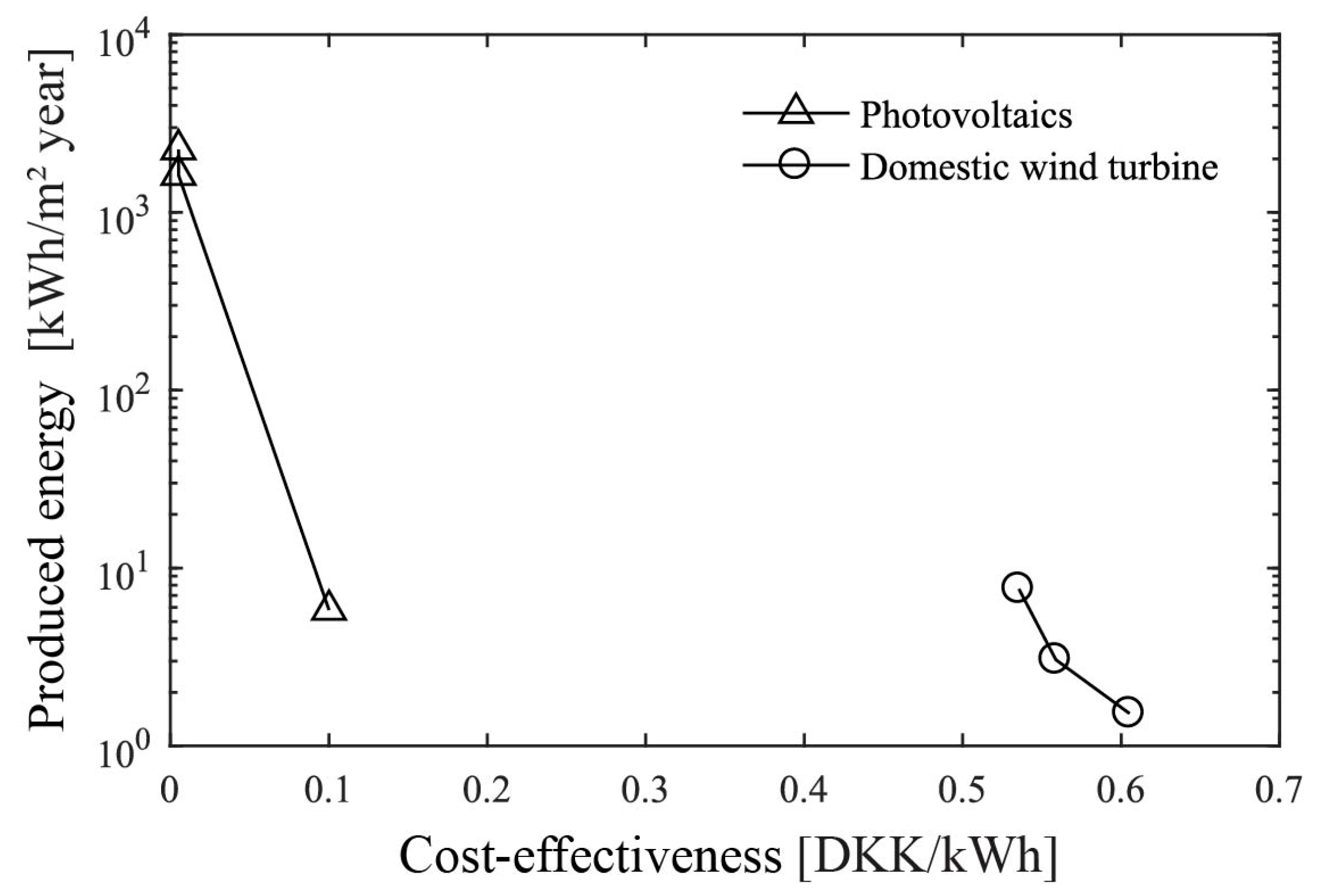
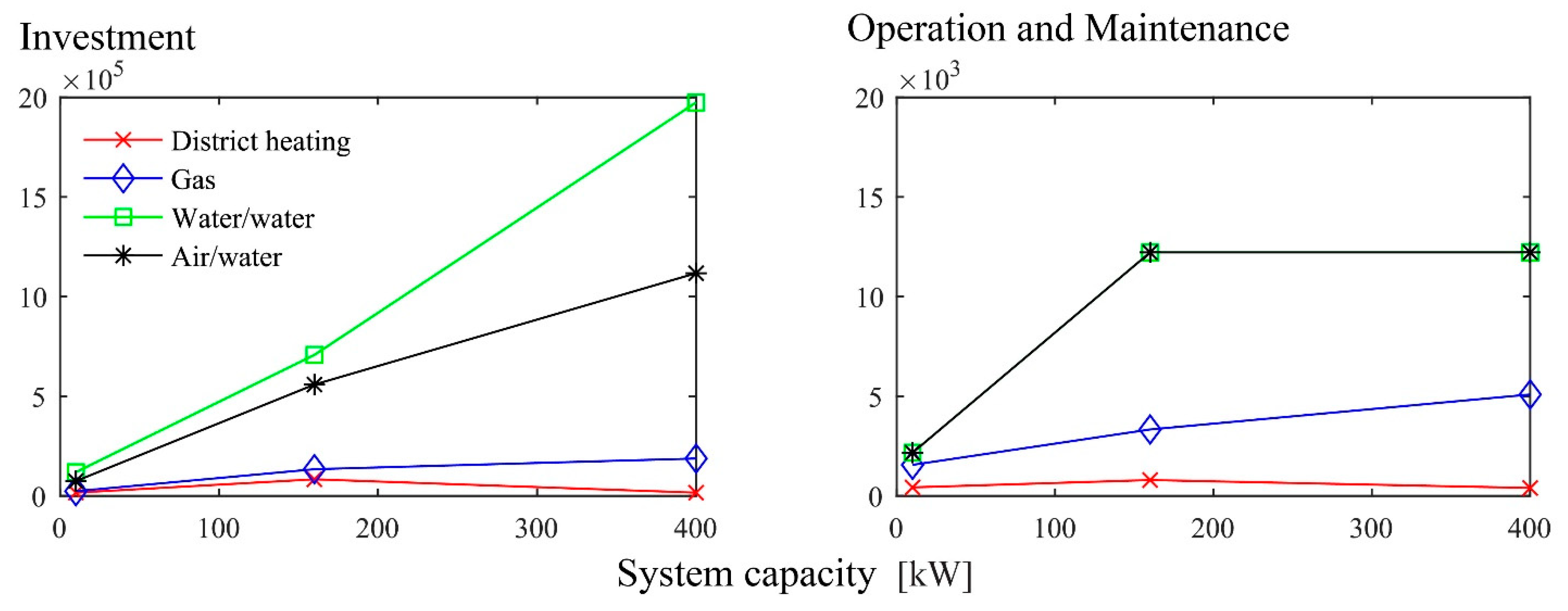
This study investigates four main energy supply systems for heating and domestic hot water and two secondary renewable energy systems. The main supply systems included in the analysis are a district heating sub-station, a natural gas boiler, a Water-to-Water (W/W) heat pump, and an Air-to-Water (A/W) heat pump. Investigated secondary supply systems are the addition of a Domestic Wind Turbine (DWT) and photovoltaic panels (PV). The selection of the investigated system types and sizes hinged on acquiring necessary input data for economical and energy performance analysis. The associated cost and technical specifications for the main and secondary energy-producing systems are accessible in Technology Data Catalogues by the Danish Energy Agency [40,41]. To investigate a possible effect of the DWT and PV system size and thereby production, three sizes deemed suitable for the building energy demand and available space are considered. For DWT, the selected system capacities are 5, 10, and 25 kW. In regard to PV, the studied sizes are 6.1, 110, and 150 kWp, corresponding to 30, 500, and 930 m2, respectively [40,41].

3.2. Single Actions

This section provides results related to the evaluation of single renovation actions for the selected case study. The results are presented in three sub-sections. The first sub-section presents a comparison of the resulting ranking of renovation actions, based on CEP and global cost (NPV). The second sub-section presents the CEP of the investigated renewable energy-producing systems. The third and final sub-section shows a relation of global cost and primary energy for the individual main energy supply systems and their combination with secondary (renewable) systems.

3.2.1. Comparison of CEP and NPV of Single Actions

Figure 2 compares single energy-efficiency actions represented in terms of the CEP from [37] to the same actions, evaluated using the LCC method and represented by NPV for a 50-year period. The comparison is made on all actions proposed in [37], but for clarity purposes, only envelope actions are shown in Figure 2. A complete list of all results is provided in Appendix A, while the detailed cost structure of each action is accessible through the Data Availability Statement. As it can be observed in Figure 2 and in the appended information, there are multiple solutions of the same element and type. These are cases with several solutions for a given element type. For example, an external wall type one with nine variations of insulation thickness or windows of the same material and class, but different opening mechanisms.
By comparing the graphs in Figure 2, a few similarities and differences can be noted. The most significant differences are the change in slope of the usable attic solutions, wall type one and two. While their CEP decreases with increase of energy savings (increased insulation thickness), the NPV for those elements increases. Furthermore, the NPV of wall types two and three are comparable to the usable attic solution. This is not the case when the CEP is applied. Nevertheless, the remaining actions maintain similar disposition (relative to each other), when applying either the CEP or NPV. For example, it is evident that wall type one, windows, attic solutions, terrace doors, and ground floor insulation all preserve the same distribution.
While the CEP represents the cost of saved kWh for a given solution over its lifetime, NPV determines the total cost over the calculation period. Furthermore, CEP considers only implementation cost, lifetime, and saved energy by the solution. In addition to that, NPV takes into account inflation, price increases, interest rate, maintenance, replacement cost, and residual value at the end of the calculation period. Even though those parameters are an inseparable part from global solution (package) evaluation, the comparison in Figure 2 shows that omitting them seems to have a limited effect on the ranking of single actions. At this relatively early stage of the methodology, it is valuable to identify actions with low investment relative to the obtained savings rather than find the solutions with the least required investment over a defined period of time. Moreover, the majority of building owners are still not completely clear on the practical use and application of LCC calculations, and its uptake is still rather weak [45]. Regarding those considerations, in combination with the great difference in calculation methods for the CEP and NPV, it can be argued that the CEP provides satisfactory results for this stage of a renovation project, despite its simplified approach.

3.2.2. CEP of Renewable Energy-Producing Systems

Figure 3 presents the CEP results for the secondary renewable energy-producing systems. The figure shows the CEP in Danish kroner per produced kWh as a function of produced energy. Both parameters are calculated using the method explained in Section 2.2 and data available in [40,41]. The energy produced by a renewable system is dependent on various technical, local, and operational parameters. The results presented in Figure 3 consider the average number of operational hours, technical and efficiency system parameters as specified in [40,41], but excludes site and system operation specifics. Thus, results in Figure 3 can be considered as an example of how different systems compare in terms of energy production and cost with optimal conditions. As the operational conditions are often limited by site characteristics (e.g., building orientation, location, roof area and slope, etc.), the produced energy is likely to be lower than that suggested in Figure 3. The CEP of the systems may also change if there is financial incentives or regulations, supporting specific types of systems.
By comparing the CEP of renewable energy production systems (Figure 3) and this of envelope actions (Figure 2), it can be stated that renewable energy production systems are more cost-effective than implementation of renovation to the building. The least cost-effective system—DWT—is comparable to the most cost-effective envelope options. The most cost-effective system in accordance to Figure 3 is the photovoltaic panels (PV), where even the smallest system is more cost-effective than any of the investigated envelope solutions. Both PV and DWT systems exhibit a reduction in the CEP with increase in capacity; thereby, the implementation of a larger system should result in reduced total cost compared to the implementation of a smaller system. Furthermore, considering that every produced kWh reduces the necessary purchased energy (if utilized directly on site), the implementation of a renewable energy system should result in a reduction of energy demand and global cost.
To check if that is true, renewable options are applied to the reference energy model (before renovation) as a secondary energy supply and investigated for both global energy and cost performance. In addition to the secondary renewable energy supply options, the reference model is also fitted with four different primary supply options, as defined in Section 2.2.

3.2.3. Global Cost and Energy Performance of Main and Secondary Energy Systems

Figure 4 shows primary energy demand and global cost for the main and secondary supply options. Global cost is presented using the NPV indicator for the applied calculation period of 50 years, while primary energy demand is found using the compliance tool BE18. Primary energy and NPV for the reference case are represented by a vertical and a horizontal dashed line, respectively (~130 kWh/m2 year and −18.22 million DKK). With that representation, cheaper solutions than the reference appear above the horizontal reference line. Consequently, solutions with lower energy demand are located to the left of the vertical reference line. The limit values for reaching NZEB, as well as voluntary renovation classes 1 and 2, are denoted by three additional vertical dashed lines. Renovation classes 1 and 2 are stated in Danish building regulations and correspond to 52.8 and 70.4 kWh/m2 year, respectively [39]. As defined in Section 2.1, reaching NZEB in a Danish concept is equivalent to 27 kWh/m2 year, which is marked by the green vertical dashed line. This representation is applied to all following figures comparing NPV and energy demand.
The different scenarios of main energy supply are first computed without any application of secondary renewable energy production. Then, each renewable system is added in a one-at-a-time manner. Figure 4 shows that the cheapest option is to run the building on natural gas; however, using gas results in higher primary energy than the reference case. As the required heat demand for district heating and gas scenarios is equal, the increase of primary energy is solely due to the applied national primary energy factors. A factor of one is applied for natural gas compared to 0.85 for district heating and 1.9 for electricity. As a consequence, in cases where the target is reaching NZEB, the natural gas case is not favored in the Danish context.
Switching from district heating to either a Water-to-Water (W/W) or Air-to-Water (A/W) heat pump results in lower primary energy demand. Given that the primary energy factor for electricity is higher than this for district heating and gas, the reduction is a consequence of the “free” energy produced by the heat pump’s high Coefficient of Performance (COP). The COP of the investigated W/W heat pump is higher (4.2) than that of the A/W heat pump (3.65); thereby, the W/W heat pump realizes higher primary energy savings. Although the W/W heat pump is approximately 55% more expensive than A/W in regard to acquisition and replacement cost, its higher efficiency brings 17% lower supply demand and 6.5% lower global cost compared to A/W. In spite of their differences, the two heat pump types are comparable. Both scenarios yield lower primary energy demand and higher NPV in comparison to the reference. Nonetheless, the cost increase is relatively small related to the achieved primary energy savings; hence, heat pumps are favored as the main heating supply solution for NZEB renovation.
Figure 4 shows that the addition of renewable electricity production results in a reduction of cost and energy demand, regardless of the system type and size. This can be explained by the assumption that all produced energy is used on site. This simplification is made, as the goal of the analysis is to identify the potential of each system rather than find the exact amount energy used on-site. Produced on-site electricity is modeled to cover the necessary demand for building operation and common spaces first, while excess production is assumed to be utilized by private apartments.
For all scenarios including DWT, increasing the system size results in a reduction of primary energy and NPV. The investigated wind turbine is cheaper than the PV systems in all scenarios, except W/W heat pump. For gas, district heating, and W/W heat pump as the main supply, the second largest PV system (110 kWp) exhibits the lowest cost. The only scenario where the largest capacity PV plant is the cheapest of the three investigated sizes is in combination with the A/W heat pump. It is also noticed that the cost difference between the two larger PV sizes is greatest for the W/W heat pump.
Overall, the performance of the studied PV and DWT systems is comparable both in terms of cost and energy production. However, the installation of a DWT requires space and a number of regulatory requirements, which cannot be fulfilled in most cases. Even so, the results indicate that if space and regulations are in place, DWT can be a viable supplementary supply option. It must be noted that both the economic and energy performance for all renewable technologies vary considerably depending on technology specifications, local conditions, legislation, funding incentives, costs, calculation methods, etc.

3.3. Compilation and Evaluation of Packages

This section provides a description for the approach used to compile renovation packages and presents the results. Furthermore, the resulting global cost and primary energy demand for the selected packages alone and in combination with main and secondary systems are presented and analyzed.
Having determined the individual effect on energy demand and knowing the cost for applying various energy efficiency actions, different energy supply sources, and renewable energy production systems, we can now use the acquired data to sort the actions and compose renovation packages. The objective of this study is to combine renovation packages based on different approaches for the selection of what a package consists of. Moreover, we identify if using cost-effectiveness as a sorting parameter can yield cost-optimal packages.
The compiled renovation packages are differentiated in three target groups, based on the predicted amount of energy savings, which are expressed in percent reduction from the reference. The level of energy savings is set to approximately 20, 40 and 60%. Naturally, packages with lower target have wider selection of possibilities, as less actions are required to reach the target. Therefore, six packages are compiled for target savings of 20%, and two are compiled for 40 and 60%.
The approach used to select the contents of packages 1–6 is to include a variety of rather random building elements, adding up to 20% savings. This is done to mimic cases where the elements to be renovated are pre-selected, but the specific solution is not. The selection of the specific element type, insulation thickness, or class is made on the basis of the energy savings and CEP. The sorting is performed on an element level, as grouped in Table A1, Table A2, Table A3, Table A4, Table A5 and Table A6 in Appendix A. Then, a selection of the specific element type is made from one or more of the tables, depending on the goal of the package. For packages 1–6, CEP and energy savings are considered to make up packages, which are expected to provide approximately 20% energy savings while still comprised with one of the most cost-effective elements.
Alternatively, the elements included in package 7 are selected on the basis of global CEP sorting, across all investigated actions. This is done with aim of identifying if selection solely based on CEP provides cost-optimal packages. Package 8 considers the same level of savings as package 7, although it focuses on reaching the target by implementing fewer building elements with large individual energy savings. For this package, the first priority is to select the building elements with large individual savings and then select the specific type based on element-sorted CEP.
Packages 9 and 10 consist of a 60% energy reduction target. Package 9 is compiled by CEP sorting on an element level, and then including all needed elements to reach approximately 60% savings, prioritizing those with large savings first. Lastly, package 10 includes all investigated elements but for the compromise of lower energy class windows and terrace doors. The resulting packages and their content details are presented in Table 2, whereas a list of all elements and their CEP value is available in Appendix A. The last two rows in Table 2 provide the predicted savings by the sum of individual contributions of renovation actions and the achieved global savings by the package.
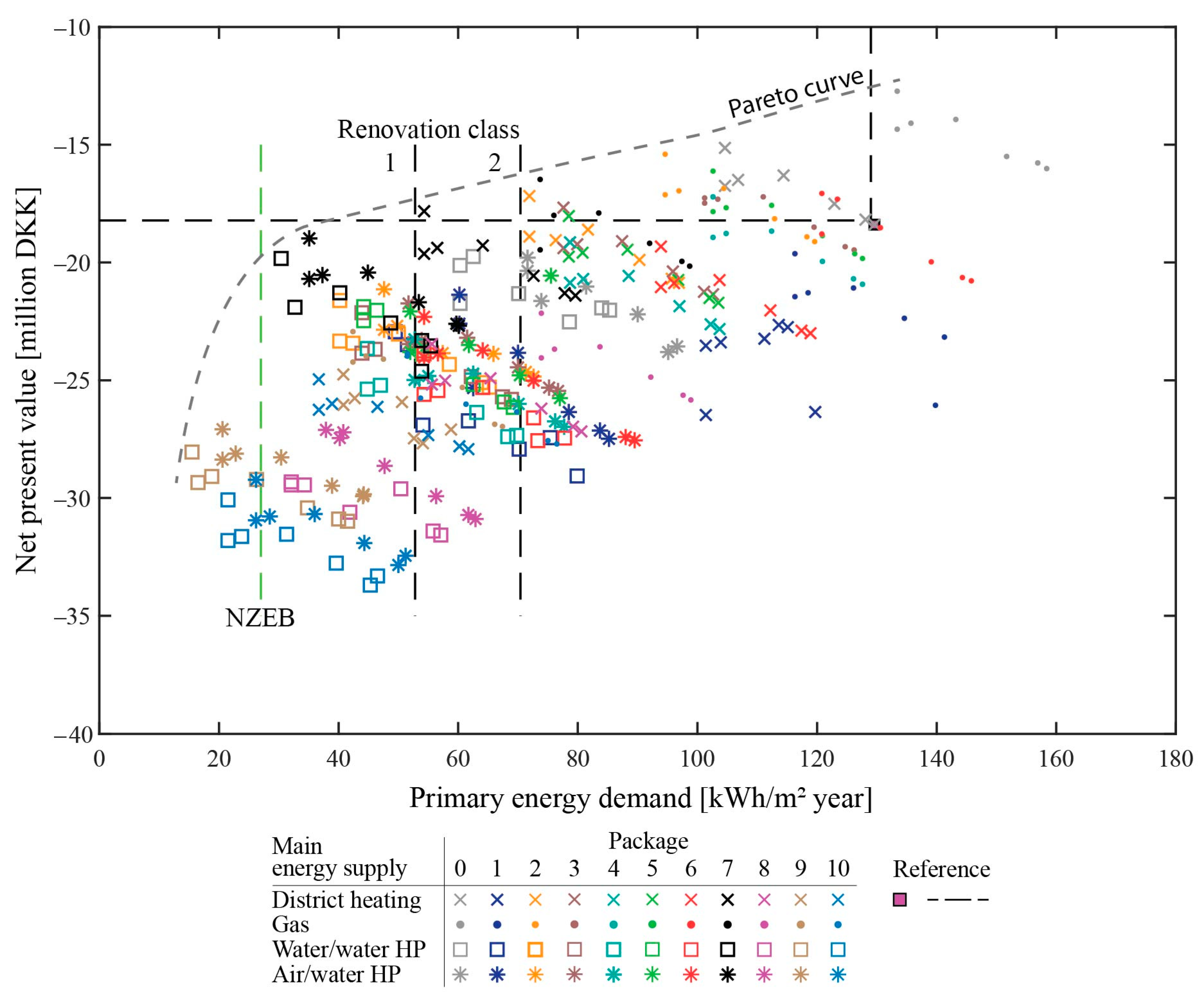
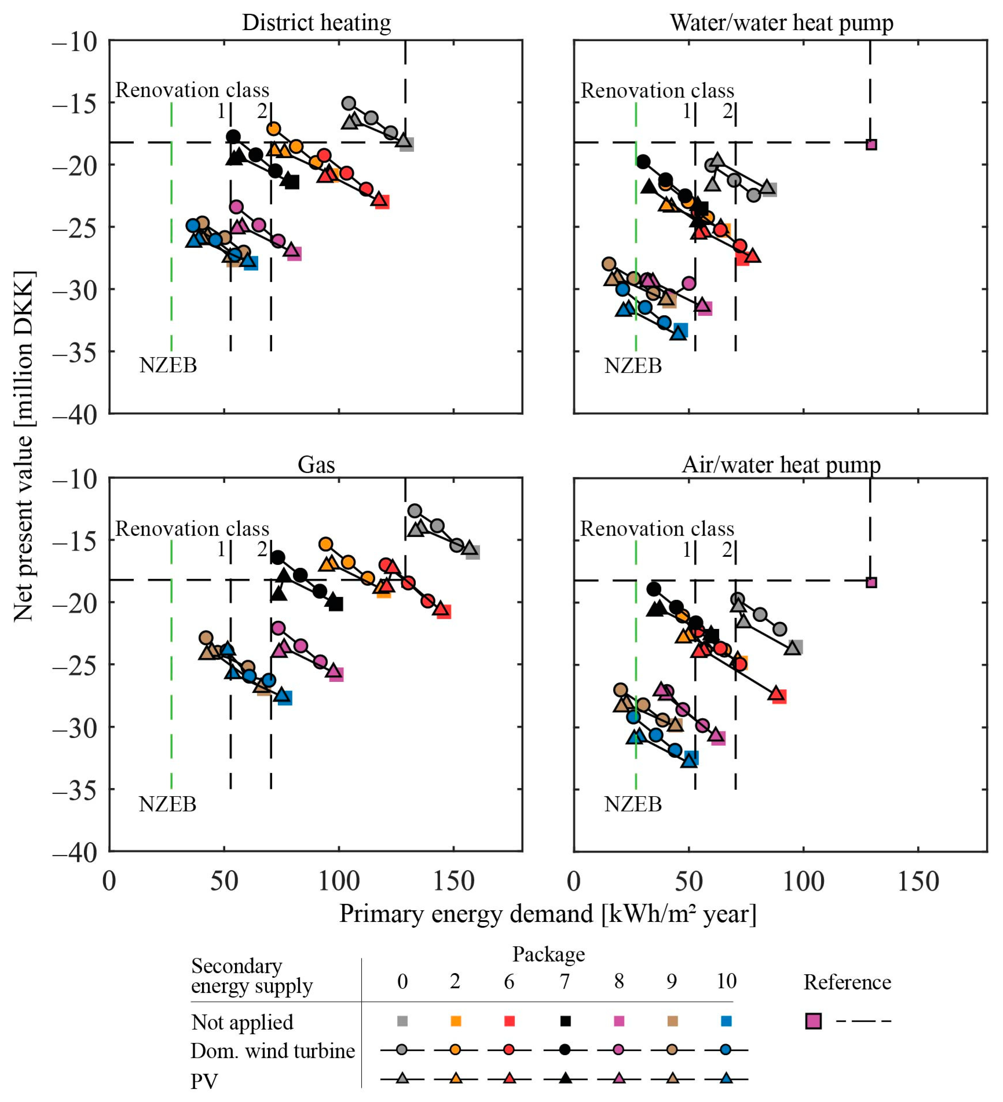
The results for NPV and primary energy demand for each of the specified renovation packages and their combination with main and secondary energy supply are presented in Figure 5. Similarly to the cost-optimality plot shown in Figure 1, all studied combinations and the resulting Pareto curve are presented for the purpose of observing the complete solution space. As the differentiation in Figure 5 is made only by the package and main supply option, there are seven identical symbols appearing for each package. Those correspond to the three studied DWT and PV systems and the main supply systems as stand-alone systems, which are all discussed in detail throughout this section. Package zero represents a change of energy-producing system and/or the addition of renewables, as presented in Figure 4.
Given the selected boundary conditions for the calculations, 12 of the 308 studied cases satisfy NZEB. Seven of those have W/W heat pumps as the primary supply and five A/W heat pumps. There are 56 solutions lying between the NZEB requirement and renovation class one, while those between the limits for renovation class one and two are 79.
As observed from Figure 5, there are a number of cases that are rather close to the NZEB target value of 27 kWh/m2 year but do not reach NZEB. Those have the potential to reach the target by means of model optimization on either the envelope or the producing system’s side. Figure 5 reveals a general tendency of increasing global cost with reduction of primary energy demand. Nevertheless, there are also solutions with significantly lowered energy demand that are comparable to the reference case total costs. The results are further analyzed for each main supply system in two ways. First, the addition of renovation packages alone is presented in Figure 6. Second, the packages are combined with the secondary energy production systems in Figure 7.
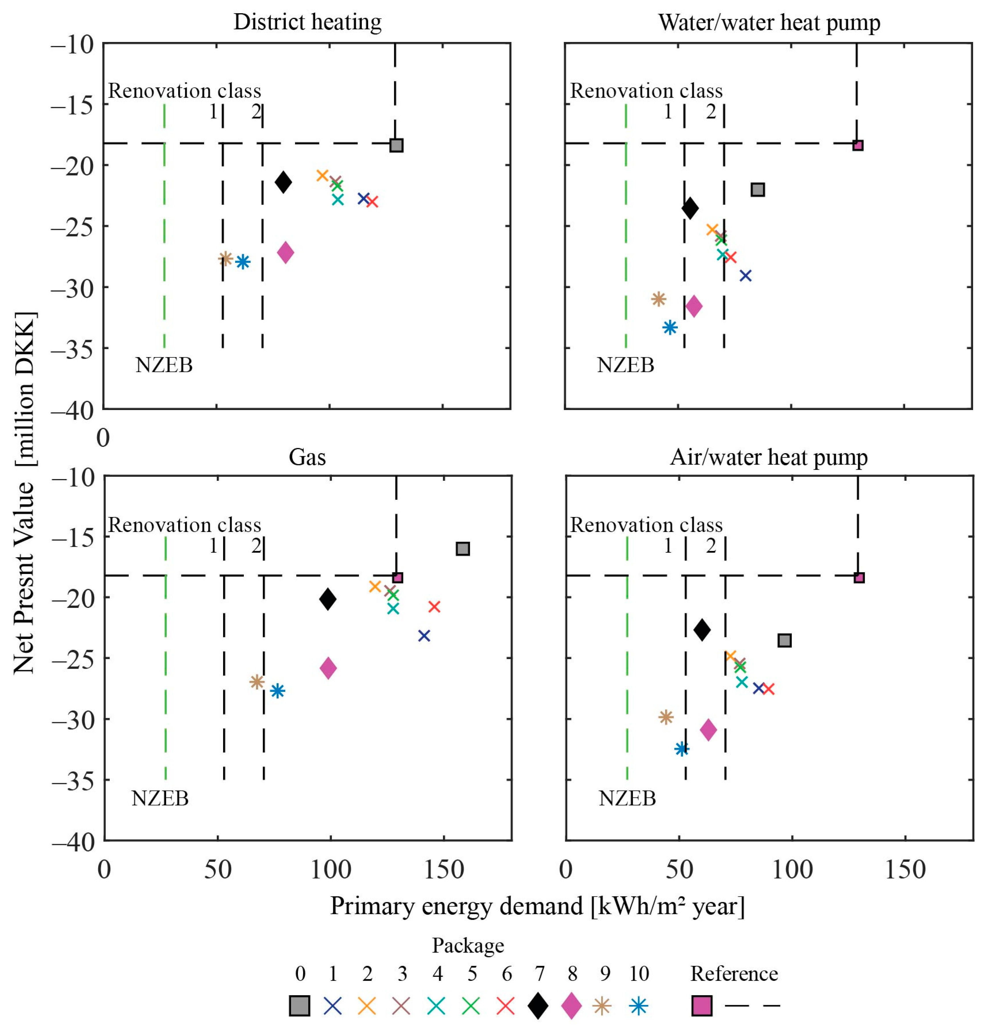
Figure 6 presents the resulting energy demand and NPV by applying the renovation packages defined in Table 2 to the reference energy model. The results are shown for each main supply type, where packages with energy-saving targets of 20, 40, and 60% are marked with an “x”, a diamond, and a star, respectively. If district heating is kept as the main supply, packages 1–6 (target savings of 20%, based on sum of individual element contributions) provide global savings in the range of 8–25% compared to the reference. As indicated at the bottom of Table 1, for some of the packages, the addition of individual savings and resulting savings based on global energy balance are equal, while for others, they differ. This confirms that the sum of savings of individual actions is not always equal to the global savings. In fact, the comparison between expected and achieved results in Table 2 shows a tendency for greater difference between the results with an increasing number of elements in a package. This is evident as packages 2–5 all constitute of two renovated elements and only for one of these are the global savings lower than the sum of individual actions. Furthermore, a mismatch between global saving and sum of individual elements is also present for packages 1 and 6–10, which comprise three or more elements. On the contrary, package 7 consist of five elements and has equal global and summed energy savings, while package 3 consist of two elements but the sum and global savings differ. This indicates that both the type and number of elements included in the package have an influence on how close the expected and achieved savings are.
Analyzing the packages with 20% target savings, it can be noted that package 2 provides the most savings for the least cost-increase (25% energy savings for 14% higher NPV compared to reference). Package 6 is the least efficient and the most expensive of the six packages, providing 8% energy reduction but 26% global cost increase. Packages 3, 4, and 5 provide comparable energy savings of approximately 20%, but they vary in NPV. Respectively, there is a 17, 25, and 19% increase in NPV for packages 3, 4, and 5. Package 1 provides an 11% primary energy reduction and 24% increase in NPV.
Even though the relative relationship between packages 1 and 6 is similar for all other supply systems, it is noticed that the type of main system can influence their order in respect to cost and energy savings. For example, packages 1 and 6 are nearly equal in terms of energy savings and cost for scenarios with district heating and A/W heat pumps, while for scenarios with gas and W/W heat pumps, their cost differs noticeably. As expected, scenarios with heat pumps bring the largest energy savings compared to the reference (35–50% savings), where in the case of W/W heat pumps, this is enough to satisfy renovation class 2.
From Figure 6, it becomes apparent that packages 7 and 8 perform equally in regard to energy reduction but with considerably different NPV values. Regardless of the applied supply system, package 7 is substantially cheaper than package 8. A possible explanation of the great cost difference can be contributed to the addition of mechanical ventilation with heat recovery to package 8. It can also be noticed that for scenarios with heat pumps, package 7 is the cheapest of all packages, while for district heating and gas, the cost and achieved savings of package 7 are comparable to those of packages 1–6. Higher energy savings outweigh the additional implementation and running cost for package 7 compared to packages 1–6. This shows that higher energy savings does not necessarily mean greater global cost; moreover, how energy savings are achieved can have a large influence on the total global cost. Considering that the approach for compiling package 7 is purely based on the CEP, sorted across all investigated elements, it can be argued that the approach can yield cost-optimal packages.
Packages 9 and 10 compare well in terms of economic and energy performance. Both of the packages include mechanical ventilation with heat recovery; thereby, they are most the expensive and comparable in cost with package 8. In all cases, package 9 is cheaper and more energy efficient than package 10. The cost difference is larger for the two heat pumps scenarios, in which case package 9 is also cheaper than package 8.
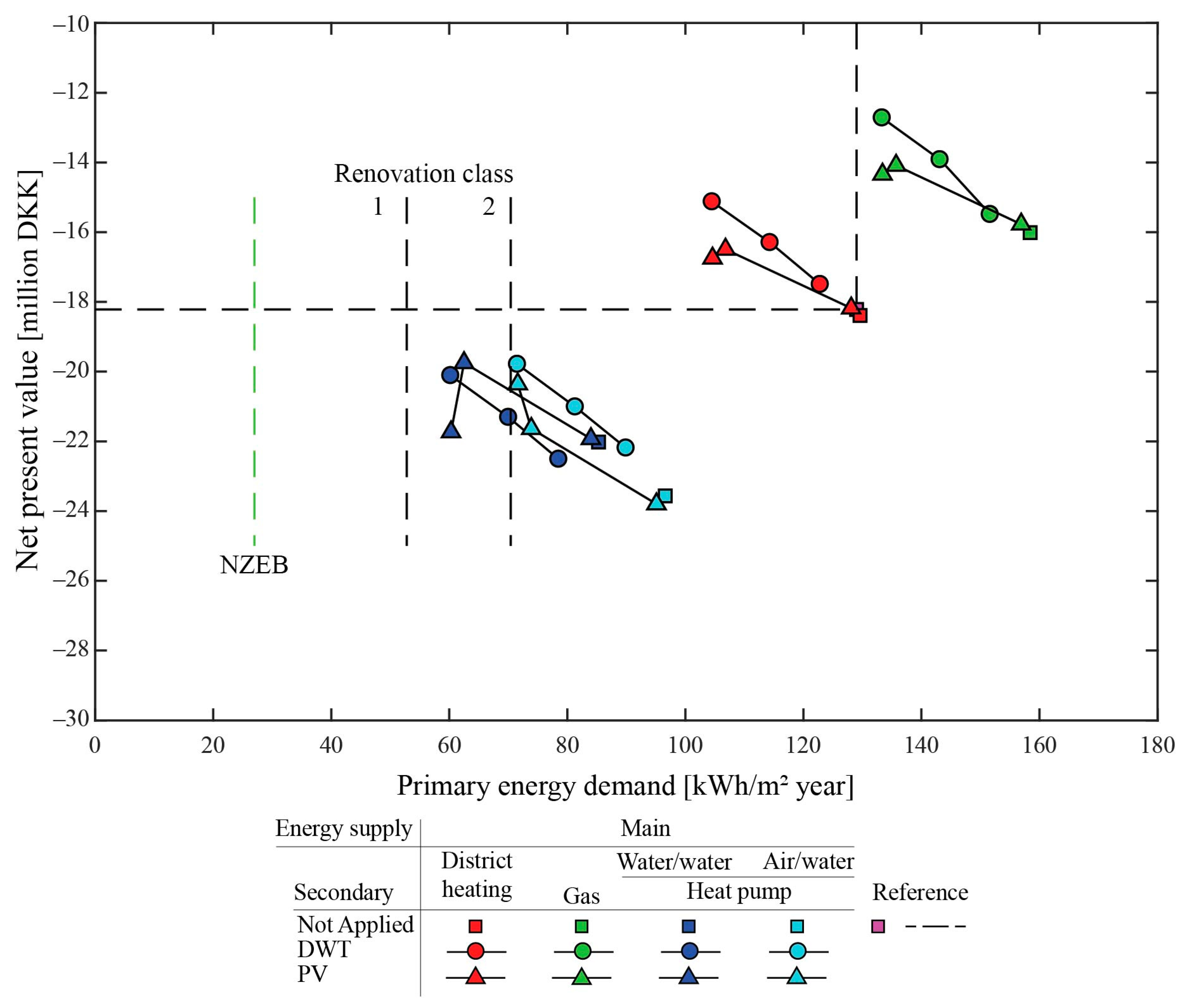
Finally, all renovation packages are combined with each of the studied renewable energy systems. Figure 7 presents the resulting energy demand and NPV, where for clarity, only the best and worst performing packages with 20% target savings are shown. The tendencies observed in Figure 4 for the addition of renewable systems alone remain unchanged when they are further combined with renovation packages. Namely, PV and DWT lower both the global cost and energy demand. The present analysis excludes the potential reduction of system capacity, resulting from achieved energy savings by a given renovation package. Further considerations in this regard may lower the global cost of energy-producing systems as a consequence of lower investment, replacement, and possibly operation and maintenance cost.
For district heating as the main supply option, only package 2 achieves renovation class two when combined with the largest sizes of PV and DWT. It is noticed that global costs for the largest DWT are also lower than the reference. Neither of the cases incorporating package 6 result in renovation class classification. Packages 7 and 8 in combination with two of the DWT or PV solutions satisfy renovation class two, where the larger system sizes reach the limit for renovation class one. The offset in global cost between packages 7 and 8 appears to remain unchanged. Despite the relatively large savings obtained from packages 9 and 10, reaching NZEB with district heating is still not possible, even with the addition of renewable secondary supply.
As explained previously, natural gas and district heating have equal heating demand; however, due to the higher primary energy factor for gas, these scenarios observe higher primary energy demand. Hence, the only solutions satisfying any of the denoted building renovation classes are also the ones with the highest savings. In fact, only a few solutions combining gas and large DWT or PV systems surpass requirements for renovation class one. The results in Figure 7 confirm that natural gas would likely not be the favored solution for cases in Denmark where the target is NZEB, even with the addition of renewable energy production. However, natural gas could be applicable if the target is global cost reduction.
Nearly all solutions incorporating heat pumps and renovation packages satisfy renovation class two. Actually, when the more efficient W/W heat pump is combined with larger PVs or DWT, renovation class 2 can be achieved without the addition of energy-saving measures (marked in gray in Figure 7). This is also true for the A/W heat pump, although only for the largest PV and DWT systems. It can be noticed that for both heat pumps types, package 7 combined with 25 kW DWT is the cheapest solution of all. Although package 7 combined with either PV or DTW does not satisfy the NZEB requirement, it can be foreseen that a small optimization of selecting one or more elements in the package with higher energy saving could make that possible. Additional reductions of about 4 and 10 kWh/m2 per year are needed for W/W and A/W heat pumps to reach the limit value, respectively. Most solutions involving packages 9 and 10 in combination with heat pumps and secondary renewables lay in the region between 27 and 52 kWh/m2 year. The solutions satisfying the NZEB requirement consist of A/W heat pumps combined with packages 9 and 110, 150 kWp PVs, or 25 kW DWT. In the case of W/W heat pumps, both packages 9 and 10 combined with the aforementioned renewables fit with the NZEB limit.

4. Discussion

The suggested methodology gives the opportunity to consider a wide variety of necessary activities and select a renovation strategy based on a structured approach. The different stages link regulatory and computational considerations for the comparison and selection of renovation actions, considering energy demand and costs.
The methodology is demonstrated using case study buildings that require extensive renovation and energy savings (80% reduction) to reach the NZEB standard. The exiting state of the selected case study provides the possibility for the application of a wide range of energy-efficiency measures and requires a substantial energy reduction. Thus, the selection of which building parts to be renovated and to what extend is crucial for reaching a cost-optimal NZEB solution. The case study results showed a number of different ways for reaching the NZEB target. Furthermore, the applied method helped to identify solutions that have the potential to reach the NZEB target with significantly reduced cost.
While the targets for the specific project at hand can vary, the method is refined for renovations targeting the NZEB standard. Currently, an NZEB is defined in the EPDB [7] as “[a] building that has a very high energy performance, as determined in accordance with Annex I. The nearly zero or very low amount of energy required should be covered to a very significant extent by energy from renewable sources, including energy from renewable sources produced on-site or nearby.” In most Member States, the limit value of how low the energy demand of the building needs to be is defined by the maximum primary energy. The limit value varies greatly from country to country in both magnitude and the way the indicator is determined. In some Member States, the indicator is a non-dimensional parameter relative to a reference building [8]. In a few countries, carbon emissions is the main indicator, while in others, emissions are used as a secondary indicator to primary energy [8]. Since the release of the EPBD, recast various definitions and calculation methods for NZEB have been applied [46]; moreover, the definitions are still evolving and changing. Therefore, the fact that the methodology is not tailored to a specific limit value but rather focused on activities to acquire and evaluate the parameters in question is considered as a strength.
For the demonstration of the method in this paper, single actions are evaluated based on cost and energy savings. The suggested approach is flexible toward the specific energy modeling method. While the presented work adopts a simple, standardized approach, it is possible to be done using other calculation methods tailored to the project needs or local requirements. The accuracy of derived energy savings is dependent on the selected method and accompanying assumptions.
Similar statements can be made for the estimation and calculation of costs. Nowadays, this is a much less regulated topic compared to energy performance, but it can be noticed that this is changing with the implementation of new emerging standards [38] and expected EPBD revision before July 2021 [47]. The suggestion for addressing costs, first on a single element level and then by LCC, is in line with a number of the key principles communicated in the Renovation Wave [6]. Addressing single actions in a simplified way may also help bridge the gap of practitioners understanding life cycle thinking.
Regardless of the applied approach, any cost results will be dependent on the depth of the analysis and the sources for prices of the different actions (database, specific tender offer, selected websites/companies, product catalogues, etc.). As discussed in Section 2.2, some cost reductions may also occur as a result of the contents of a renovation package. Especially for packages with large energy savings, the total cost may be reduced due to synergies of the performed actions and reduction of the required system capacity.
Figure 8 gives an example of the corresponding investment cost (left) alongside the operation and maintenance cost (right) as a function of system capacity. Data for each of the four compared systems are obtained from the Danish technology data catalogues [40,41]. The comparison shows that for some systems such as district heating and gas, there would not be great differences in the resulting investment or operation and maintenance cost due to reduction of the required capacity. This differs for heat pumps, as an evidently considerable investment cost reduction can be achieved by reducing the size of a heat pump. The strongest cost-dependence on the size is observed for W/W heat pumps. Operation and maintenance costs for the two heat pumps are equal and remain the same for 160 and 400 kW systems, but they decrease for systems smaller than 160 kW.
The investment, operation, and maintenance costs are only a couple of the parameters involved in the methodology. To identify which model parameters have the highest impact on the CEP and LCC results, a sensitivity analysis of energy and cost calculations is necessary. Furthermore, such will determine the robustness of the solutions and the methodology overall.
The comparison of CEP and NPV of individual building elements showed the same disposition for nearly all investigated elements. This suggests that a selection of package contents based on NPV would not be very different to a selection based on CEP. However, as presented in the paper, the two parameters are obtained by different methods, where NPV requires a greater number of inputs and arguably grater complexity and time. The CEP provides the possibility for choosing actions by considering the cost of saved kWh and gives the possibility of applying different approaches for compiling a package. Sorting on an element level, one can apply the CEP to select specific types from a range of options. The applied methodology for the compilation of packages showed that selected actions vary with different project goals. Sorting across all possible investigated options provided the package with the most savings for the least cost.
The CEP of renewable energy-producing systems was shown to be much lower than those of energy-efficiency actions by means of building renovation. This was further confirmed through LLC analysis, as nearly all investigated renewable solutions resulted in both lowered global cost and energy demand. The results indicate that with high self-consumption, large system sizes bring the biggest global cost reduction. Nevertheless, in a few scenarios with PV, a local optimal is present where the second largest system is with the lowest global cost.
Comparing the methodology proposed in this paper with the work presented in [24], it can be argued that the CEP parameter helps to reduce the economic gap between cost-optimal and NZEB solutions, as it seeks to implement a package that delivers the most energy savings for the least investment. While the aim of the study [14] was to find building system configurations that comply with a minimum share of renewables in an Italian setting, the achieved results for applicable renewable systems are in good agreement with those found in this paper: namely, heat pumps combined with PV systems and small solar heating plants. In a similar manner, results related to cost-optimality presented in [31,32] have a comparable composition of optimal package, as found in this paper. In fact, both papers found that interventions of multiple building parts and systems are necessary to reach NZEB. In [31], the cost-optimal package consists of basic insulation of all building elements, a heat pump or gas boiler, and renewable production. A number of similarities can also be observed between results for the cost-optimal renovation of a Finish apartment building provided in [29] and this study. First, mechanical ventilation and additional insulation were not cost-effective solutions, despite the large share of saved energy. In addition, heat pumps provide the best economic performance, whereas PVs are especially recommendable due to the achievable reduction of global cost and energy demand.
However, neither of the papers evaluate single actions in the same manner as proposed in this paper. A comparable approach that considers environmental impact, instead of global cost, is presented in [34]. The method ranks thermal insulation and finds that there are several solutions significantly reducing energy demand, but those are also characterized with different environmental impacts.
Association of the proposed method with a more comprehensive Multi-Objective Parametric Analysis (MOPA) [35] can also be drawn. The MOPA method is divided in three stages, which are different in essence from the stages presented here; however, the approach is generally similar. Although MOPA is applied to lightweight addition instead of the whole building, the first stage consists of analyzing components separately and then performing analysis for obtaining optimum design parameters. The third stage deals with the analysis of renewable energy resources. Indeed, MOPA is a parametric methodology that provides a much wider range of solutions. On the contrary, those solutions stem from the parameter variation, rather than real-life products, as is the case in this method.
The proposed method can be used as template for guiding the building owner through the tasks, activities, and decisions needed for the selection of a renovation plan to reach the NZEB standard. Furthermore, consultants and energy-saving companies could also apply it to compose renovation scenarios. Currently, the method accounts for energy and economic indicators only, but it can be expanded to account for additional indicators describing CO2 emissions, life cycle analysis, comfort, etc.

5. Conclusions

The paper presents a methodology for the selection and evaluation of renovation alternatives with the nearly Zero Energy Building (NZEB) target. The outline of the method can serve as a flowchart that presents steps for data acquisition and handling in a structured manner, with the aim of simple, transparent, and justified decision making. The methodology is applied to a case study, where the performed analysis points to the following conclusions.
The cost-effectiveness parameter (CEP) can be useful for estimating cost–benefits of various energy producing and saving actions. Although some discrepancies are noticed when comparing single action ranking based on the CEP and NPV, most actions retain their relative order.
The CEP can be used for the sorting of renovation actions across different levels, depending on the focus of the project. As demonstrated, soring across pre-selected building element types, or all elements, yields different contents for renovation packages. The results also showed that creating a package, solely based on the CEP, provides a package with the largest savings for the least cost increase. Although the results in this area are promising, further research including a higher number of packages is needed.
Even though the selected case study buildings require an energy demand reduction of about 80%, applying the proposed method converged several solutions satisfying the NZEB target. This can partly contribute to the large amount of energy-saving measures applied in this study; however, in cases where the initially determined single actions are limited and none of their combinations satisfies the targets, the user can iterate back to creating one or more single actions or variants of the already determined actions.
Analyses related to renewable energy production show that in nearly all cases, it is cheaper to implement a renewable energy system than do nothing. A considerable difference in both energy and cost is noted for the investigated main supply systems. Heat pumps prove to be most favorable when the target is NZEB. It was shown that the primary energy factor plays a big role in reaching a limit value for building energy class.
Further studies should explore the robustness of the proposed method and the sensitivity of the different economic and energy parameters. Another viable topic could be to expand the current methodology with more evaluation parameters beyond economics and energy efficiency. Those could be related to a reduction of CO2 emissions, greenhouse gases, or comfort indicators for the occupants.

Author Contributions

Conceptualization, all authors; methodology, Y.I.A.; validation, all authors; formal analysis, Y.I.A.; investigation, Y.I.A.; resources, P.K.H. and M.Z.P.; data curation, Y.I.A.; writing—original draft preparation, Y.I.A.; writing—review and editing, all authors; visualization, Y.I.A.; supervision, M.Z.P. and P.K.H.; project administration, M.Z.P. and P.K.H.; funding acquisition, P.K.H. All authors have read and agreed to the published version of the manuscript.

Funding

This research was funded by European Union’s Horizon 2020 Research and Innovation program, grant number 768576.

Data Availability Statement

The data presented in this study are openly available in Zenodo repository at https://doi.org/10.5281/zenodo.4452206.

Conflicts of Interest

The authors declare no conflict of interest.

Appendix A

The following appendix contains a list of results for primary energy savings, implementation cost, assumed lifespan, and the resulting cost-effective parameter (CEP) for single renovation actions, proposed in [37]. The Net Present Value (NPV), resulting from the LCC analysis presented in Figure 2, is also shown for each action. For ease of the reader, each building part is presented in a separate table, accompanied by a brief explanation of the considered renovation action types and their variations. The names of the actions are kept as presented in [37] and are consistent with the accompanying data files provided in the Data Availability Statement. The name consists of an abbreviation of the building part, followed by a number and letter, representing the type of solution and variation of insulation thickness (energy class for windows), respectively.
Table A1 shows data for external wall solutions. Three different renovation types consider removal of the existing lightweight façade and external insulation of the load-bearing brick wall.
  • External wall type 1—Insulation, new lightweight timber construction, and wooden plank facades.
  • External wall type 2—Insulation, new external brick façade.
  • External wall type 3—Commercially available ROCKWOOL REDArt solution.
Detailed calculations of the implementation costs presented in Table A1 can be found in the Data Availability Statement.
Table A1. Single renovation actions for external walls.
NameImplementation CostEnergy SavingsLifetimeCEPNPV
DKKkWh/m2 YearYearDKK/Saved kWhDKK
Ex. Wall-1a1,232,1396.2400.81−19,888,992
Ex. Wall-1b1,244,5879.2400.58−19,598,135
Ex. Wall-1c1,298,29311.3400.50−19,456,154
Ex. Wall-1d1,342,34212.7400.47−19,374,918
Ex. Wall-1e1,403,07013.6400.46−19,357,620
Ex. Wall-1f1,431,02714.3400.45−19,304,343
Ex. Wall-1g1,493,64315.1400.44−19,305,656
Ex. Wall-1h1,493,64315.5400.43−19,315,806
Ex. Wall-2a3,277,27910.2401.39−22,361,253
Ex. Wall-2b3,339,31112.0401.22−17,093,374
Ex. Wall-2c3,402,80513.3401.13−17,034,224
Ex. Wall-2d3,527,10715.0401.05−22,178,831
Ex. Wall-2e3,587,19615.6401.03−22,193,705
Ex. Wall-2f3,645,71616.1401.02−22,212,767
Ex. Wall-3a3,151,94011.5401.20−21,559,802
Ex. Wall-3b3,445,41812.7401.10−21,762,299
Ex. Wall-3c3,807,33814.5400,97−21,996,700
Ex. Wall-3d3,267,03815.1400.93−21,332,489
Investigation of attic renovation is examined for two overall scenarios. The first is a scenario where the function of the attic is kept the same (common storage and drying facilities). This case considers removal and re-establishment of the wooden floor and a number of insulation types and thicknesses, which are all presented in Table A2. The results for the second scenario presented in Table A3 include the same insulation types and thicknesses but exclude re-establishment of the floor. This changes the space to unusable but reduces cost considerably. The different attic renovation types are based on the type and class of insulation as follows:
  • Attic 1—Flexi batts insulation class 37: a 70—h 245 mm
  • Attic 2—Flexi batts insulation class 34: a 95—c 145 mm
  • Attic 3—Rolled batts insulation class 37: a 38—d 170 mm
  • Attic 4—Blown-in granule of mineral wool class 40: a 70—d 150 mm
  • Attic 5—Blown-in granule of paper wool, class 40: a 50—d 150 mm
Table A2. Single renovation actions for attic floor slab, with re-establishment of the floor (usable attic space).
NameImplementation CostEnergy SavingsLifetimeCEPNPV
DKKkWh/m2 YearYearDKK/Saved kWhDKK
Attic 1-a2,493,0702.6400.21−19,161,528
Attic 1-b2,499,7903.0400.19−19,127,272
Attic 1-c2,529,0643.3400.21−19,141,125
Attic 1-d2,553,1163.6400.22−19,160,525
Attic 1-e2,586,1702.9400.24−18,985,270
Attic 1-f2,601,5143.0400.25−19,208,829
Attic 1-g2,601,5143.1400.28−19,253,766
Attic 1-h2,635,5903.2400.34−19,246,288
Attic 1-h + a2,724,2664.4400.32−19,243,021
Attic 1-h + b2,730,9864.7400.32−19,223,721
Attic 1-h + c2,760,2604.9400.32−19,252,529
Attic 1-h + d2,784,3125.0400.34−19,271,929
Attic 1-h + e2,832,7105.2400.35−19,316,520
Attic 1-h + f2,832,7105.3400.5−19,320,233
Attic 1-h + g2,866,7865.5400.37−19,374,143
Attic 1-h + h2,866,7865.6400.37−19,359,187
Attic 2-a2,541,0343.1400.18−19,083,424
Attic 2-b2,574,8163.3400.26−19,129,327
Attic 2-c2,609,3823.3400.29−19,176,641
Attic 2-c + a2,746,0223.5400.40−19,406,345
Attic 2-c + b2,779,8043.9400.40−19,413,363
Attic 2-c + c2,814,3704.3400.40−19,420,298
Attic—3 a2,526,8103.0400.23−18,974,049
Attic—3 b2,556,0843.3400.24−19,189,801
Attic—3 c2,569,6223.6400.24−19,190,261
Attic—3 d2,612,812-2.9-400.27−19,033,265
Attic—3 d + a2,735,2283.8400.39−19,348,016
Attic—3 d + b2,764,5024.1400.39−19,354,390
Attic—3 d + c2,778,0404.4400.37−19,339,894
Attic—3 d + d2,821,2304.7400.39−19,386,294
Attic 4-a2,642,0202.1400.60−19,409,651
Attic 4-b2,697,9842.6400.57−19,437,343
Attic 4-c2,789,7843.1400.59−19,527,173
Attic 4-d2,935,8483.6400.68−19,681,057
Attic 5-a2,705,7282.1400.74−19,38,2581
Attic 5-b2,769,6992.5400.71−19,405,679
Attic 5-c2,873,2293.0400.73−19,486,254
Attic 5-d3,037,7383.5400.82−19,632,620
Table A3. Single renovation actions for attic floor slab, without re-establishment walking bridge (unusable attic space).
NameImplementation CostEnergy SavingsLifetimeCEPNPV
DKKkWh/m2 YearYearDKK/Saved kWhDKK
Attic 1.1-a127,8191.9403.30−21,728,534
Attic 1.1-b134,5392.4402.98−21,701,756
Attic 1.1-c163,8132.8402.80−21,514,905
Attic 1.1-d187,8653.0402.64−21,742,486
Attic 1.1-e220,9193.3403.16−22,099,647
Attic 1.1-f236,2633.5403.10−21,799,764
Attic 1.1-g270,3393.6403.02−21,852,178
Attic 1.1-h270,3392.8402.99−21,696,641
Attic 1.1-h + a359,0154.3402.40−21,621,588
Attic 1.1-h + b365,7365.4402.28−21,822,133
Attic 1.1-h + c395,0105.4402.23−21,635,133
Attic 1.1-h + d419,0625.4402.21−21,879,315
Attic 1.1-h + e452,1165.4402.16−21,922,410
Attic 1.1-h + f467,4605.4402.14−21,942,574
Attic 1.1-h + g501,5355.4402.10−21,778,133
Attic 1.1-h + h501,5355.4402.07−21,987,510
Attic 2.1-a175,7833.6402.95−21,457,654
Attic 2.1-b209,5652.9402.85−21,727,739
Attic 2.1-c244,1323.5402.89−21,782,531
Attic 2.1-c + a380,7723.5402.91−22,012,235
Attic 2.1-c + b414,5543.9402.70−22,245,081
Attic 2.1-c + c449,1204.3402.53−22,033,665
Attic—3.1 a161,5602.4403.01−21,750,432
Attic—3.1 b190,8342.8402.83−21,779,240
Attic—3.1 c204,3723.0402.66−21,772,222
Attic—3.1 d247,5623.3403.19−21,835,072
Attic—3.1 d + a369,9783.5402.71−21,725,984
Attic—3.1 d + b399,2523.9402.58−21,960,280
Attic—3.1 d + c412,7904.3402.45−21,953,262
Attic—3.1 d + d455,9804.5402.36−22,007,139
Attic 4.1-a276,7701.2404.06−21,960,206
Attic 4.1-b332,7341.8403.57−22,011,826
Attic 4.1-c424,5342.4403.24−22,148,018
Attic 4.1-d570,5983.0403.04−22,271,991
Attic 5.1-a340,4781.2404.16−21,933,135
Attic 5.1-b404,4491.7403.77−21,972,685
Attic 5.1-c507,9792.3403.42−22,060,737
Attic 5.1-d672,4882.9403.21−22,216,077
Investigated single renovation actions for change of windows are presented in Table A4. The variation between the renovation actions is frame material, energy class, and opening mechanism for the window. The differentiation of saved energy is made only for the different frame materials and energy classes. In other words, the different opening mechanisms are assumed to have equal energy savings if they are of the same material and energy class [37].
Table A4. Single renovation actions for change of windows.
NameImplementation CostEnergy SavingsLifetimeCEPNPV
DKKkWh/m2 YearYearDKK/Saved kWhDKK
Wood-B fixed1,272,55013.7300.5519,590,699
Wood-B top-hinged1,555,48513.7300.6720,003,144
Wood-B side-hinged1,861,96613.7300.8019,786,233
Wood-B 2 section side-hinged2,204,89213.7300.95
Wood-B 3 section side-hinged2,377,62713.7301.03
Wood-B ”Dannebrog” side-hinged2,378,73213.7301.03
Wood-A fixed1,652,80617.6400.4219,060,557
Wood-A top-hinged1,952,55817.6300.5019,497,505
Wood-A side-hinged2,368,84917.6300.8120,104,607
Wood-A 2 section side-hinged2,781,85617.6300.95
Wood-A 3 section side-hinged3,065,09017.6301.05
Wood-A ”Dannebrog” side-hinged2,893,14617.6300.99
Plastic-B fixed1,119,04614.8300.4519,381,684
Plastic-B top-hinged882,68814.8300.3519,037,026
Plastic-B 2 section side-hinged1,337,57114.8300.5419,700,464
Plastic B ”Dannebrog” side-hinged2,776,93414.8301.12
Plastic-A fixed1,189,55717.3300.4118,962,563
Plastic-A top-hinged1,408,27417.3300.5919,281,572
Plastic-A 2 section side-hinged1,440,47317.3300.5019,700,464
ALU-B fixed1,759,20014.4300.7319,920,367
ALU-B side-hinged2,873,59914.4301.1821,193,426
ALU-A fixed1,773,79718.4300.5819,675,237
ALU-A side-hinged2,653,51718.4301.5821,766,026
Table A5 presents results concerning changing of terrace doors. Similarly to windows, the solutions for terrace doors differ by frame material and energy class.
Table A5. Single renovation actions for change of terrace doors.
NameImplementation CostEnergy SavingsLifetimeCEPNPV
DKKkWh/m2 YearYearDKK/Saved kWhDKK
Plastic-B1,259,0606.6301.1318,967,286
Plastic-A1,188,5705.7301.0618,766,026
Wood/Alu-A1,401,6507.4301.0719,817,891
Table A6 shows values concerning insulation of the basement ceiling. Due to height limitation, the investigated insulation thicknesses are limited to 120 mm. Basement insulation type 1 consist of four thicknesses of mineral wool class 37, whereas, type 2 considers mineral wool insulation class 34 for four varying thicknesses.
Table A6. Single renovation actions for insulation of the basement ceiling.
NameImplementation CostEnergy SavingsLifetimeCEPNPV
DKKkWh/m2 YearYearDKK/Saved kWhDKK
BS 1a286,4271.4400.5719,210,946
BS 1b297,0021.4400.5919,224,045
BS 1c303,7701.4400.6119,231,603
BS 1d333,2401.4400.6619,266,702
BS 2a328,6711.5400.6319,253,783
BS 2b303,7701.5400.5819,224,125
BS 2c345,2951.5400.6619,224,125
BS 2d379,3041.5400.7319,314,090

References

  1. REN21 Secretariat. 2020 Global Status Report for Buildings and Construction: Towards a Zero-Emissions, Efficient and Resilient Buildings and Construction Sector; REN21 Secretariat: Paris, France, 2020. [Google Scholar]
  2. European Commission. Stepping up Europe’s 2030 Climate Ambition Investing in a Climate-Neutral Future for the Benefit of Our People; European Commission: Brussels, Belgium, 2020; Volume 53, pp. 1689–1699. [Google Scholar]
  3. Economidou, M.; Laustsen, J.; Ruyssevelt, P.; Staniaszek, D. Europe’s Buildings Under the Microscope. A Country-by-Country Review of the Energy Performance of Buildings; BPIE: Brussels, Belgium, 2011. [Google Scholar]
  4. European Commission. Directive (EU) 2018/844 of the European Parliament and of the Council of 30 May 2018 Amending Directive 2010/31/EU on the Energy Performance of Buildings and Directive 2012/27/EU on Energy Efficiency. Off. J. Eur. Union 2018, 156, 75–91. [Google Scholar]
  5. Esser, A.; Dunne, A.; Meeusen, T.; Quaschning, S.; Denis, W.; Hermelink, A.; Schimschar, S.; Offermann, M.; John, A.; Reiser, M.; et al. Comprehensive Study of Building Energy Renovation Activities and the Uptake of Nearly Zero-Energy Buildings in the EU Final Report; European Commission: Brussels, Belgium, 2019; p. 87. [Google Scholar]
  6. The European Commission. Communication from the Commission to the European Parliament, the Council, The European Economic and Social Committee and the Committee of the Regions. A Renovation Wave for Europe—Greening Our Buildings, Creating Jobs, Improving Lives; The European Commission: Brussels, Belgium, 2020; Volume 662, p. 27. [Google Scholar]
  7. The European Parliament and the Council of the European Union. Directive 2010/31/EU of the European Parliament and of the Council of 19 May 2010 on the Energy Performance of Buildings (recast). Off. J. Eur. Union 2010, 153, 13–35. [Google Scholar]
  8. Building Performance Institute Europe (BPIE). Nearly Zero Energy Buildings Definitions Across Europe; BPIE: Brussels, Belgium, 2015; pp. 18–22. [Google Scholar]
  9. Staniaszek, D.; Kockat, J.; Vitali Roscini, A. A Review of Eu Member States’ 2020 Long-Therm Renovation Strategies; BPIE: Brussels, Belgium, 2020. [Google Scholar]
  10. Ma, Z.; Cooper, P.; Daly, D.; Ledo, L. Existing building retrofits: Methodology and state-of-the-art. Energy Build. 2012, 55, 889–902. [Google Scholar] [CrossRef]
  11. Abdul Hamid, A.; Farsäter, K.; Wahlström, Å.; Wallentén, P. Literature review on renovation of multifamily buildings in temperate climate conditions. Energy Build. 2018, 172, 414–431. [Google Scholar] [CrossRef]
  12. Firlag, S.; Piasecki, M. NZEB renovation definition in a heating dominated climate: Case study of Poland. Appl. Sci. 2018, 8, 1605. [Google Scholar] [CrossRef] [Green Version]
  13. Cunha, F.O.; Oliveira, A.C. Comparison of nZEB indicators for hotel renovations under different European climatic conditions. Int. J. Low Carbon Technol. 2020, 16, 246–257. [Google Scholar] [CrossRef]
  14. De Luca, G.; Ballarini, I.; Lorenzati, A.; Corrado, V. Renovation of a social house into a NZEB: Use of renewable energy sources and economic implications. Renew. Energy 2020, 159, 356–370. [Google Scholar] [CrossRef]
  15. Mørck, O.; Almeida, M.; Ferreira, M.; Brito, N.; Thomsen, K.E.; Østergaard, I. Shining examples analysed within the EBC Annex 56 project. Energy Build. 2016, 127, 991–998. [Google Scholar] [CrossRef] [Green Version]
  16. Brambilla, A.; Salvalai, G.; Imperadori, M.; Sesana, M.M. Nearly zero energy building renovation: From energy efficiency to environmental efficiency, a pilot case study. Energy Build. 2018, 166, 271–283. [Google Scholar] [CrossRef]
  17. Aparicio-Gonzalez, E.; Domingo-Irigoyen, S.; Sánchez-Ostiz, A. Rooftop extension as a solution to reach nZEB in building renovation. Application through typology classification at a neighborhood level. Sustain. Cities Soc. 2020, 57, 102109. [Google Scholar] [CrossRef]
  18. Assimakopoulos, M.N.; De Masi, R.F.; Fotopoulou, A.; Papadaki, D.; Ruggiero, S.; Semprini, G.; Vanoli, G.P. Holistic approach for energy retrofit with volumetric add-ons toward nZEB target: Case study of a dormitory in Athens. Energy Build. 2020, 207, 109630. [Google Scholar] [CrossRef]
  19. Fotopoulou, A.; Semprini, G.; Cattani, E.; Schihin, Y.; Weyer, J.; Gulli, R.; Ferrante, A. Deep renovation in existing residential buildings through façade additions: A case study in a typical residential building of the 70s. Energy Build. 2018, 166, 258–270. [Google Scholar] [CrossRef]
  20. Salvalai, G.; Sesana, M.M.; Iannaccone, G. Deep renovation of multi-storey multi-owner existing residential buildings: A pilot case study in Italy. Energy Build. 2017, 148, 23–36. [Google Scholar] [CrossRef]
  21. Pihelo, P.; Kalamees, T. Commissioning of moisture safety of nZEB renovation with prefabricated timber frame insulation wall elements. Wood Mater. Sci. Eng. 2019, 16, 110–117. [Google Scholar] [CrossRef]
  22. Kampelis, N.; Gobakis, K.; Vagias, V.; Kolokotsa, D.; Standardi, L.; Isidori, D.; Cristalli, C.; Montagnino, F.M.; Paredes, F.; Muratore, P.; et al. Evaluation of the performance gap in industrial, residential & tertiary near-Zero energy buildings. Energy Build. 2017, 148, 58–73. [Google Scholar]
  23. Sağlam, N.G.; Yılmaz, A.Z.; Becchio, C.; Corgnati, S.P. A comprehensive cost-optimal approach for energy retrofit of existing multi-family buildings: Application to apartment blocks in Turkey. Energy Build. 2017, 150, 224–238. [Google Scholar] [CrossRef]
  24. Baldoni, E.; Coderoni, S.; D’Orazio, M.; Di Giuseppe, E.; Esposti, R. From cost-optimal to nearly Zero Energy Buildings’ renovation: Life Cycle Cost comparisons under alternative macroeconomic scenarios. J. Clean. Prod. 2021, 288, 125606. [Google Scholar] [CrossRef]
  25. European Parlament. Commission Delegated Regulation (EU) No 244/2012 of 16 January 2012 supplementing Directive 2010/31/EU of the European Parliament and of the Council on the energy performance of buildings by establishing a comparative methodology framework for calculating. Off. J. Eur. Union 2012, 81, 18–36. [Google Scholar]
  26. IEA. Methodology for Cost Effective Energy and Carbon Emission Optimization in Building Renovation; Annex 56; International Energy Agency: Paris, France, 2017. [Google Scholar]
  27. Almeida, M.; Ferreira, M. Cost effective energy and carbon emissions optimization in building renovation (Annex 56). Energy Build. 2017, 152, 718–738. [Google Scholar] [CrossRef]
  28. Stocker, E.; Tschurtschenthaler, M.; Schrott, L. Cost-optimal renovation and energy performance: Evidence from existing school buildings in the Alps. Energy Build. 2015, 100, 20–26. [Google Scholar] [CrossRef]
  29. Niemelä, T.; Kosonen, R.; Jokisalo, J. Cost-effectiveness of energy performance renovation measures in Finnish brick apartment buildings. Energy Build. 2017, 137, 60–75. [Google Scholar] [CrossRef] [Green Version]
  30. Ortiz, J.; i Casas, A.F.; Salom, J.; Garrido Soriano, N.; i Casas, P.F. Cost-effective analysis for selecting energy efficiency measures for refurbishment of residential buildings in Catalonia. Energy Build. 2016, 128, 442–457. [Google Scholar] [CrossRef] [Green Version]
  31. Moran, P.; O’Connell, J.; Goggins, J. Sustainable energy efficiency retrofits as residenial buildings move towards nearly zero energy building (NZEB) standards. Energy Build. 2020, 211, 109816. [Google Scholar] [CrossRef]
  32. Guardigli, L.; Bragadin, M.A.; Della Fornace, F.; Mazzoli, C.; Prati, D. Energy retrofit alternatives and cost-optimal analysis for large public housing stocks. Energy Build. 2018, 166, 48–59. [Google Scholar] [CrossRef]
  33. Ferreira, M.; Almeida, M.; Rodrigues, A. Cost-optimal energy efficiency levels are the first step in achieving cost effective renovation in residential buildings with a nearly-zero energy target. Energy Build. 2016, 133, 724–737. [Google Scholar] [CrossRef]
  34. Amani, N.; Kiaee, E. Developing a two-criteria framework to rank thermal insulation materials in nearly zero energy buildings using multi-objective optimization approach. J. Clean. Prod. 2020, 276, 122592. [Google Scholar] [CrossRef]
  35. Amer, M.; Hamdy, M.; Wortmann, T.; Mustafa, A.; Attia, S. Methodology for design decision support of cost-optimal zero-energy lightweight construction. Energy Build. 2020, 223, 110170. [Google Scholar] [CrossRef]
  36. Zavadskas, E.K.; Antucheviciene, J.; Kalibatas, D.; Kalibatiene, D. Achieving Nearly Zero-Energy Buildings by applying multi-attribute assessment. Energy Build. 2017, 143, 162–172. [Google Scholar] [CrossRef]
  37. Antonov, Y.I.; Heiselberg, P.; Flourentzou, F.; Pomianowski, M.Z. Methodology for Evaluation and Development of Refurbishment Scenarios for Multi-Story Apartment Buildings, Applied to Two Buildings in Denmark and Switzerland. Buildings 2020, 10, 102. [Google Scholar] [CrossRef]
  38. European Committee for Standardization. DS/EN 15459-1:2017 Energy Performance of Buildings—Economic Evaluation Procedure for Energy Systems in Buildings—Part 1: Calculation Procedured, Module M1—14; BSI: London, UK, 2017. [Google Scholar]
  39. Ministry of Transport, Building and Housing. Danish Building Regulations 2018—Executive Order No. 1615 of 13 Dec. 2017 (in Force); Ministry of Transport, Building and Housing: Copenhagen, Denmark, 2018.
  40. Danish Energy Agency and Energinet. Technology Data for Individual Heating Plants; Danish Energy Agency: Copenhagen, Denmark, 2016.
  41. Danish Energy Agency. Technology Data for Energy Plants for Electricity and District Heating Generation; Danish Energy Agency: Copenhagen, Denmark, 2019; pp. 1–374.
  42. Aggerholm, S. SBi-Anvisning 213: Bygningers Energibehov Beregningsvejledning; Build Institut For Byggeri: Aalborg, Denmark, 2018. [Google Scholar]
  43. Aalborg University. LCCbyg; Aalborg University: Aalborg, Denmark, 2020. [Google Scholar]
  44. Danish Energy Agency. Regulation and Planning of District Heating in Denmark; Danish Energy Agency: Copenhagen, Denmark, 2016.
  45. Haugbølle, K.; Raffnsøe, L.M. Rethinking life cycle cost drivers for sustainable office buildings in Denmark. Facilities 2019, 37, 624–638. [Google Scholar] [CrossRef]
  46. Marszal, A.J.; Heiselberg, P.; Bourrelle, J.S.; Musall, E.; Voss, K.; Sartori, I.; Napolitano, A. Zero Energy Building—A review of definitions and calculation methodologies. Energy Build. 2011, 43, 971–979. [Google Scholar] [CrossRef]
  47. European Parliament Legislative Train Schedule. Available online: https://www.europarl.europa.eu/legislative-train/theme-a-european-green-deal/file-revision-of-the-energy-performance-of-buildings-directive (accessed on 26 January 2021).
Figure 1. Overview of methodology for obtaining least-cost renovation scenarios for specific building projects.
Applsci 11 04141 g001
Figure 2. Comparison between the cost-effectiveness parameter (CEP) adapted from [37] (top) and net present value (bottom) for selected energy efficiency actions.
Applsci 11 04141 g002
Figure 3. The cost-effectiveness parameter (CEP) for renewable energy-producing technologies.
Applsci 11 04141 g003
Figure 4. Comparison of the four studied main supply options, combined with secondary renewable energy-producing systems. No energy-saving measures applied.
Applsci 11 04141 g004
Figure 5. Primary energy as a function of net present value for all investigated packages (308 + reference).
Applsci 11 04141 g005
Figure 6. Energy renovation packages, shown for each of the investigated primary energy supply options.
Applsci 11 04141 g006
Figure 7. Selected renovation packages shown for each main supply option.
Applsci 11 04141 g007
Figure 8. Investment (left) and operation and maintenance (right) costs as a function of system capacity for selected energy-producing systems.
Applsci 11 04141 g008
Table 1. U-values of building envelope elements in existing state prior renovation. Adapted from [37].
Building ElementU-Value [W/m2 K]
External wall0.58
Windows2.9
Attic slab0.35
Basement/ground floor slab1.48
Table 2. Contents and classification of investigated renovation packages. Included building elements in a renovation package are marked with “X”, which is located with respect to the variated element properties.
Energy Reduction %20 40 60
ElementMaterialInsulationClass/Type12345678910
WallTimber finish220 mmclass 37 XX
245 mmXXX XX
315 mm X
Timber floor
finish
465 mmclass 37X X X
Attic95 mmclass 34 X
490 mmclass 37 XX
Ground floorTimber finish45 mmclass 37X X
45 mmclass 34 X
WindowsPlasticN.Aclass A X X
class B X XX X
Terrace doorWoodN.Aclass A X
PlasticN.Aclass A X XX
N.Aclass B X
Heating and DHWPipe network40 mmuniversal XX
50 mmmatts XX
DHWPumpN.Acirculation X XX
0.175 decentral with heat recovery X
Ventilation0.15 X
0.1 X
Sum of individual actions% savings20252120201839526466
Global savings of package112572020839395852
Publisher’s Note: MDPI stays neutral with regard to jurisdictional claims in published maps and institutional affiliations.

