Semi-Active Magnetic Levitation System for Education


1
Department of Mathematics, Universitat Politècnica de Catalunya-BarcelonaTech (ESEIAAT), 08222 Terrassa, Spain
2
Electrotechnical Department, Universidade Tecnológica Federal do Paraná (UTFPR), Cornélio Procópio CEP 86300-000, Brazil
3
Future Technology Research Center, National Yunlin University of Science and Technology, 123 University Road, Section 3, Douliou, Yunlin 64002, Taiwan
4
Department of Electrical Engineering, University of Zanjan, Zanjan 45371-38791, Iran
*
Author to whom correspondence should be addressed.
†
These authors contributed equally to this work.
Appl. Sci. 2021, 11(12), 5330; https://doi.org/10.3390/app11125330
Submission received: 10 May 2021
/
Revised: 5 June 2021
/
Accepted: 7 June 2021
/
Published: 8 June 2021
Abstract
:This paper describes how to construct a low-cost magnetic levitation system (MagLev). The MagLev has been intensively used in engineering education, allowing instructors and students to learn through hands-on experiences of essential concepts, such as electronics, electromagnetism, and control systems. Built from scratch, the MagLev depends only on simple, low-cost components readily available on the market. In addition to showing how to construct the MagLev, this paper presents a semi-active control strategy that seems novel when applied to the MagLev. Experiments performed in the laboratory provide comparisons of the proposed control scheme with the classical PID control. The corresponding real-time experiments illustrate both the effectiveness of the approach and the potential of the MagLev for education.
1. Introduction
Known in the literature simply as MagLev, the magnetic levitation system comprises an actuator, usually a coil, producing an electromagnetic force that actuates upon an object. The object, usually containing either metal or a magnet, levitates according to the actuator’s electromagnetic force. Magnetic levitation systems have been intensively studied due to their wide range of applications, such as in magnetically levitated vehicles [1,2], electrodynamic suspension devices [3,4], magnetic bearings, levitating high-speed rotors [5,6,7], and flywheel energy storage systems [8,9,10]. Levitating an object through an electromagnetic force is usually accompanied by a feedback loop. In this case, a sensor measures the object’s position and sends the position information to the controller, which is responsible for regulating the current passing through the coil. The regulated current then produces a corresponding electromagnet force that keeps the object levitating at the desired position. As largely documented in the literature, controlling the object’s position is difficult, mainly because the MagLev shows a nonlinear, unstable behavior (e.g., [11,12,13]).
Many attempts have been made to control the MagLev system. For instance, some studies have verified the effectiveness of the classical PID control in levitating an object [14,15,16]. A subsequent study has shown that the sliding-mode control outperforms the classical PID control [17]. Another study has also improved the traditional PID by introducing the so-called fractional-order PID control with a soft computing approach [11]. In [18], the authors present a comparison between the sliding-mode control and the fractional-order sliding mode control, emphasizing the benefits of the latter. A different study raises the concept of generalized PI controller, showing clear advantages with respect to the traditional PID [19]. These investigations together indicate that controlling the MagLev is difficult, motivating the development of a plethora of control strategies. This paper also contributes to this development, as detailed below.
Promoting the study of the MagLev in an educational environment has been the practice of many instructors [20], motivated by the challenge associated with students’ learning of how to deal with electromagnetic forces to levitate an object [21]. A famous learning experiment was carried out with the participation of undergraduate students at the Massachusetts Institute of Technology, USA; the instructor asked students to construct their own magnetic levitation kit under the instructor’s supervision. This experiment suggested a positive learning experience from the involved students [21,22]. It seems this educational experiment has motivated other researchers to pursue similar investigations, striving to construct their own low-cost magnetic levitation systems [23,24,25].
This paper’s main contribution is to show how to construct a novel low-cost magnetic levitation system for educational purposes. Although recognizing many MagLev models in the literature, we present a novel design that employs easily found, low-cost spare parts. Using the components and source code described here, instructors and students can construct their own low-cost MagLev devices. By doing so, instructors and students can enrich the learning experience and practice hands-on training regarding relevant electronic topics, such as sensors, actuators, electronic circuit building, microcontroller programming, electromagnetism, and control systems. This paper describes the step-by-step necessary to construct a MagLev from scratch—all the diagrams and source code are freely available (see Remark 1). Understanding how the electromagnetic force works under feedback control is an important component in the electrical engineering curriculum, as quoted in [21,22]. The main implication of this paper is providing instructors and students with access to that knowledge, thus improving the learning experience. As a by-product, this paper discusses some of the difficulties researchers may face when handling electromagnetic forces. For instance, we bring the reader’s attention to the fact that the hysteresis in the electromagnet complicates the task of controlling the MagLev—experimental data illustrate this assertion. Additionally supported by experimental data, we show how ineffective the classical PID control is, thus confirming other investigations [11,17]. In [23], the authors use a position sensor, like us, but also a current sensor, increasing the cost. Moreover, from a control design point of view, using only the Hall effect sensor position is a challenge that has not yet been solved. In addition, to enhance the control algorithm, the authors considered a semi-active system: the input is only activated to face the gravitational force; i.e., the electromagnetic force only works to attract the levitated object. To overcome such difficulties, we present an anti-windup control. Even though the anti-windup control is not novel in the literature, its application in the MagLev seems useful, as the experimental data suggest.
The contributions of this paper can be summarized as follows:
- The construction of a low-cost MagLev device for education.
- A semi-active PID-like controller for the MagLev, which is an unstable system. The controller uses only the object’s position for feedback (no other information is available to the controller).
The remainder of this paper is as follows: Section 2 describes the devices used to assemble the MagLev, and presents some of the device’s limitations, highlighting the pros and cons; the control strategy implemented in the Maglev is detailed in Section 2, and the corresponding experimental data, as well as discussions are shown in Section 3. The concluding remarks are stated in Section 4.
2. Material and Methods
Before presenting the details about the implementation of the magnetic levitation system (MagLev), we recall how a MagLev prototype should work [21,22]. The MagLev contains a coil, which is assembled as an electromagnet. The electromagnet represents the MagLev control system’s actuator. By regulating the current passing through the coil, the MagLev controls the electromagnetic force the electromagnet generates. The MagLev employs an algorithm to control the current in the coil. The algorithm is responsible for regulating the induced electromagnetic force, which in turn counteracts the effect of the gravitational force acting on the object. The algorithm requires real-time measurements from the position of the object being levitated. This task is accomplished through a Hall-effect sensor, as detailed below. From the practical viewpoint, the low-cost magnetic levitation prototype consists of an electromagnet, a Hall-effect sensor model A1324 from Allegro(c), an Arduino Uno microcontroller, and a power amplifier, as depicted in Figure 1. It is necessary to use a computer to program the algorithm into the Arduino Uno; in this project, we use a small single-board computer known as Raspberry-Pi (see Figure 2).
Figure 3 presents a schematic that displays the construction of the prototype. The Hall-effect sensor monitors the position of the object being levitated. This sensor’s analog voltage signal is measured by the Arduino Uno microcontroller (MC) through an analog-to-digital converter (ADC). The control algorithm running into the microcontroller then calculates the necessary control value that will be supplied to the electromagnet by using a pulsed-width-modulated output pin. This process is accomplished in the discrete-time domain with a sampling rate fixed at ten milliseconds.
2.1. Actuator
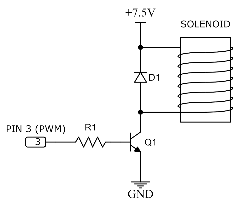
The MagLev’s actuator is an electromagnet (i.e., a solenoid coil). The electromagnet is handmade, as detailed below. A bolt with dimensions of M20 × 250 mm (hexagon head) is used as the core of the solenoid coil, as suggested in [22,25]. The wire is closely wound around the bolt—the wire used is the enameled copper wire with a diameter of 1 mm (110 m of wire). After it was built, the electromagnet had both the inductance of 15 mH and the resistance of 2.4 . The electromagnet was manually manufactured by wrapping a coil with epoxy around a ferrite core. The circuit that drove the electromagnet in the experiments is depicted in Figure 4. As can be seen, the Arduino Uno generates the PWM signal that controls the current flow through the coil.
The object being levitated is a neodymium disc magnet N42 with a weight of g and dimensions of 1/2" × 1/8". The Neodymium disc is attached to a transparent plastic for the sake of a better visual appreciation of the controlled levitation experiment (see Remark 1).
2.2. Sensor
The MagLev’s sensor chosen to measure the levitated object’s position is a Hall-effect sensor; see Figure 5. The motivation for using this kind of sensor stems from the fact that it gives analog measurements, not to mention its low-cost acquisition. An option would be using an optic sensor [26] since it has higher measurement accuracy; however, this sensor seems to be not only more sensitive to disturbances from either light or dust [20] (p. 198) but also more expensive than the Hall-effect sensor [27].
2.3. Microcontroller
Arduino Uno is a low-cost, open-source microcontroller board, widely accepted by the research community [28]. In the MagLev, the Arduino Uno implements the control algorithm. Its additional task is to send the corresponding experimental data to a Raspberry Pi board (see [29] for further details about the Raspberry Pi board). Note that any computer can be used in place of the Raspberry Pi board, yet we opt for it because it represents the cheapest solution.
2.4. Implementation Cost
Table 1 details the cost of the MagLev, excluding the computer, monitor, keyboard, and mouse, these being necessary to program the source code into the Arduino Uno. It is worth mentioning that the total cost seems compatible with a low-cost device since its assemblage depends only on open-source technology. The components in Table 1 were selected according to what the market had to offer, paying particular attention to the task of minimizing the overall cost.
2.5. Control Algorithm
The proposed PID-like controller is model free and does not depend on the system model. However, Appendix A presents the mathematical model to understand the experiment better. The proposed control law aims to enable the system output d to track the ideal output under a semi-active approach. This means that the control is only activated in one direction, opposite to gravitational force, introducing a challenge control design, in contrast with, for instance, [14,18,23,30,31,32], where the active approach is employed. Moreover, the maximum voltage is stated at 5 V; however, in the literature, its maximum is usually 12 V [19]. Considering that the Arduino Uno works with voltage ranging from 0 to V, we must introduce hard saturation to the input:
By recalling that represents the distance, and considering that the control strategy requires the speed of the object, we can use the Euler approximation method to compute the object’s speed, for example, , as
where denotes the board sampling time. In the equipment, seconds is used. The integral term reads as
Parameter a must be introduced to stabilize discrete integration. To avoid the drift of the element when the controller becomes saturated (i.e., integrator windup), we impose that
where represents a threshold value to be chosen. Additionally, we consider , since the Arduino Uno converts the voltage representation of 0–5 V into a PWM signal of 0–255 units (8 bits). First, we recall the classical PID control for the sake of experimental comparisons:
Appendix A presents the mathematical model for the MagLev system, along with the linearized representation, allowing one to select the PID parameters in (5) using, for instance, pole placement. We suggest that the control algorithm to the MagLev is a straightforward adaptation of the well-known anti-windup PID control [33], which, in our case, reads as
The control parameters , , and are positive constants. To perform the comparison, we use the same parameter values in (5) and (6).
It was observed in the laboratory that hysteresis was the main difficulty to achieve the levitation, despite the control method. It is well known that the magnetic flux does not disappear completely, as the electromagnetic core still retains some of its magnetism, even when the current has stopped flowing in the coil [34] (Ch. 1.6). Moving the input signal to the linear region of the hysteretic loop by adding a constant DC current is the simplest method to solve this problem, but with the disadvantage of adding noise, see [35]. Thus, the input voltage must be modified by a constant in (5) and (6) to diminish the hysteresis produced by the electromagnet [36]. Thus, the real implemented control is and defined as
where the integral term is subject to (4). Note that D is added to mitigate the variability of the residual magnetic flux due to the semi-active magnetic control scheme. The term then has a practical motivation and it comes from trial and error experiments. A video was made to show this phenomena: https://youtu.be/giaySAGlwAY (access on 7 May 2021).
2.6. Limitations
The designed prototype faces some limitations. Some of them are due to the low-cost solution, while others are due to the difficulties posed by handling the electromagnetic forces, as detailed below.
- Arduino Uno microcontroller. Despite being a low-cost solution, the Arduino Uno limits the speed of numerical evaluations. In addition, it works only with positive voltage (i.e., ). To handle this situation, we develop a semi-active control law to compensate the gravitational force, as described in the following.
- The electromagnet can produce hysteresis, a phenomenon documented in the literature [34] (Ch. 1.6). Moreover, the Hall-effect sensor may become inaccurate due to the corresponding hysteresis [36]. In this case, the sensor measures an unreal distance d, depending on whether the object moves in the sensor’s direction or not—Figure 6 illustrates this phenomenon through experimental data. Additionally, the Hall-effect sensor is sensitive to the magnetic field generated by nearby electrical wires.
- The anti-windup PID controller (6) is model free, so it was tuned empirically for the best results possible, minimizing the position error. In addition, the semi-active approach implies a difficulty in obtaining a ‘clean’ levitation, as shown in the experiment; see https://youtu.be/giaySAGlwAY (access on 7 May 2021).
- The PWM signal driving the electromagnet creates a certain level of noise in the circuit, leading to instability. The capacitor attached to the output of the Hall-effect sensor diminishes the amplitude of that noise.
3. Results and Discussion
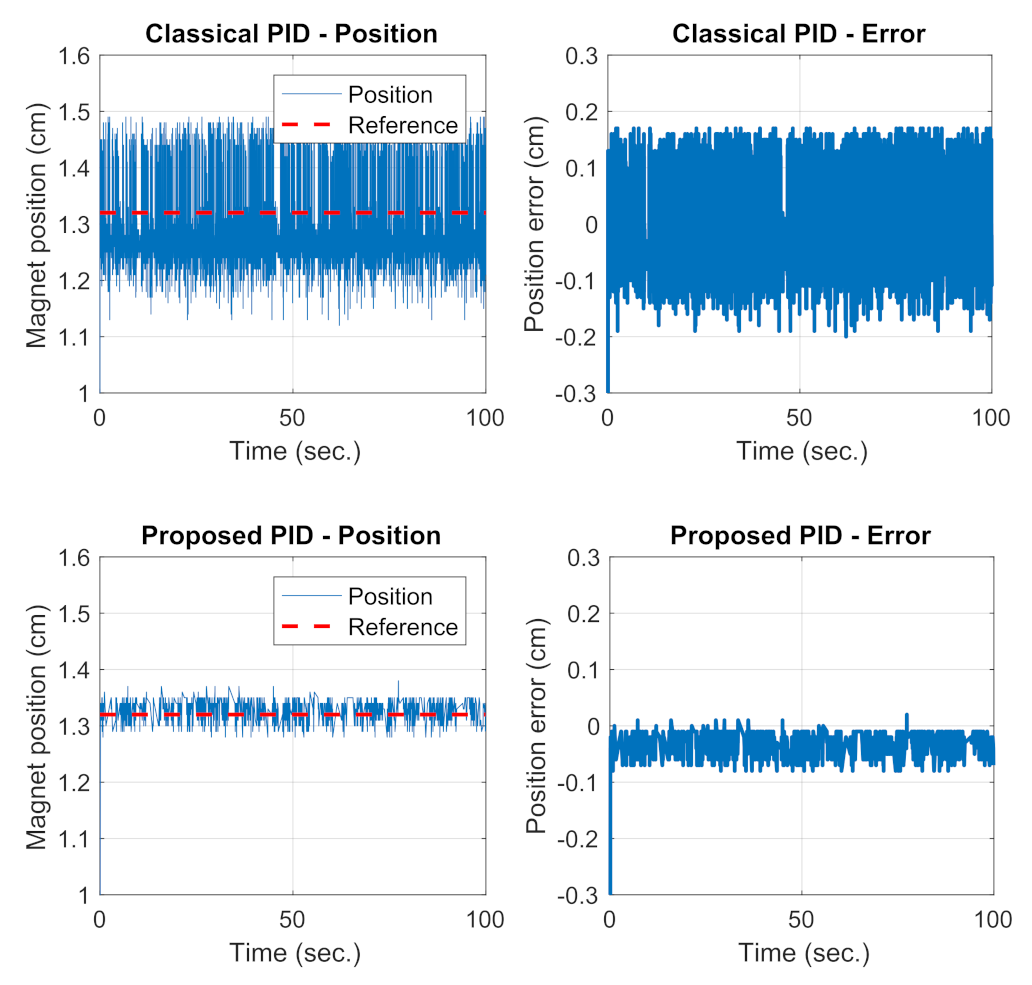
Experiments are carried out in the laboratory to check the effectiveness of the proposed MagLev. The experimental data are measured and recorded (see Remark 1 in connection). The goal is to levitate an object at the position cm. For a comparison between the anti-windup control (6) and the classical PID control (5), we consider the statistical mean value error as , where N represents the quantity of steps used in the experiment.
First, the control parameters in (5) must be defined. The proposed controller is model free and does not depend on the system model. However, Appendix A presents the linearized system, allowing one to select the PID parameters in (5) using, for instance, pole placement. Table 2 presents the control parameter nominal values. Then, experiments are carried out to perform these values minimizing [19]. Notice that the hard input saturation (1) limits the trial of these parameters. Appendix B presents the Arduino Uno source code used in this paper.
Table 2 shows the nominal and empirically optimized control parameters for both controllers, (7) and (8). As shown in Table 3, the proposed control strategy in (8) outperforms the classical PID control. The data are also illustrated in Figure 7 and Figure 8. A visual inspection confirms that the control (8) greatly diminishes the error of the object’s position when compared to the error produced by the classical PID control. This finding represents a contribution of (8) in controlling the MagLev.
Remark 1.
A video showing the experiment was recorded, and it is freely available at https://youtu.be/giaySAGlwAY (access on 7 May 2021). All the data and source code used in this manuscript are also freely available on GitHub at github.com/labcontrol-data/MagLev and archived in Zenodo [37] (access on 7 May 2021).
Discussion
From the educational viewpoint, learning how to deal with electromagnet forces represents an exciting challenge. In particular, constructing a MagLev device from scratch is an enriching experience [22].
The experimental data led us to some conclusions. First, building a low-cost MagLev requires specific skills developed during the assemblage process. Unavoidably, the trial and error attempts push the designer’s learning process forward. Undoubtedly, a hands-on approach helps to improve their learning curve [22]. Second, designing a control strategy working upon an electromagnet may instigate the designer’s curiosity even more. As an example, we developed the control (6), which seems to be novel, despite being a direct adaptation of the anti-windup PID control [33]. However, the main challenge of our proposal is to face the semi-active control system with a hard input saturation.
Certain project limitations are observed, such as the presence of noise, oscillations, and hysteresis (see a discussion in Section 2.6). Some of those limitations come as a side effect of the low-cost strategy, yet overcoming them encourages creativity, which is beneficial from the educational viewpoint.
4. Concluding Remarks
This paper shows how a prototype of a magnetic levitation system (MagLev) can be built. All the steps necessary to construct the MagLev from scratch are detailed. Creating the MagLev from scratch can be an enriching learning experience, helping instructors and students learn about essential components covered in the curriculum of electrical engineering [22]. Thus, this paper presents a contribution to education, covering a wide range of topics, such as electronics, electromagnetism, and control systems.
The experimental data in particular suggest that the MagLev is a tool that instructors and students can use to learn about control systems in practice. Even novel control strategies can be checked in practice, observing the pros and cons, as documented in Section 3. These features, associated with the low-cost solution, represent an essential step towards facilitating engineering education.
Author Contributions
Conceptualization, L.A., A.N.V., and G.P.-V.; methodology, L.A., A.N.V., S.M., and G.P.-V.; software, L.A. and G.P.-V.; validation, L.A. and G.P.-V.; formal analysis, S.M. and A.N.V.; writing—original draft preparation, G.P.-V., A.N.V., and L.A.; writing—review S.M. All authors have read and agreed to the published version of the manuscript.
Funding
This research was funded in part by the Ministry of Science and Innovation, State Research Agency of the Spanish Government through grant DPI2016-77407-P (MINECO/AEI/FEDER, UE), and in part by the Brazilian agency CNPq under Grant 305998/2020-0; 421486/2016-3.
Institutional Review Board Statement
Not applicable.
Informed Consent Statement
Not applicable.
Data Availability Statement
Data supporting the reported results can be provided by the authors upon reasonable request.
Conflicts of Interest
The authors declare no conflict of interest.
Abbreviations
The following abbreviations are used in this manuscript:
| ADC | Analog-to-digital converter; |
| GND | voltage reference ground; |
| MagLev | magnetic levitation; |
| MC | microcontroller; |
| PID | proportional integral derivative controller; |
| PWM | pulse width modulation. |
Appendix A. MagLev Mathematical Model
Figure 4 shows the electromagnetic system model. The force applied by the electromagnet on the levitating magnet can be closely approximated as
where k is a constant that depends on the geometry of the system [34]. The parameters of the electromagnetic levitation system are determined as in Table A1. It follows from Newton’s second law that
where is the vertical position of the levitating magnet measured from the bottom of the coil, is the current through the electromagnet, m is the mass of the levitating magnet, and g is the acceleration due to gravity. Moreover, from Kirchhoff’s voltage law, we have

Table A1.
Model parameters.
| Parameter | Value |
|---|---|
| k | Kg m/sA |
| R | |
| L | 15 mH |
| m | Kg |
| g | m/s |
| cm |
We assume that the current wave will not be dramatically affected by the induced polarization, so we can use the slowly varying amplitude approximation [38], where it is assumed that the envelope of a forward travelling wave pulse varies slowly in time compared to a period or wavelength. Thus, we can consider that , and the relation between the control input (voltage ) and the current is as follows:
The MagLev system Equation (A2) is then
Letting be the state of the system, the standard state description can be written as (we omit the time variable t):
The equilibrium points of the system are at:
where is the required voltage to suspend the levitating magnet at . Consider and . Then, Jacobian linearization of the system about the equilibrium point is
Consider and . The transfer function of the linearized system is
A PID controller (5) can be designed for this system using the pole assignment method [39], paying special attention to optimizing the disturbance response and providing good damping to the closed-loop response. From (5), , and is the Laplace transform of the reference. Then, the transfer function of the closed-loop system is
Using the experimental parameter value in Table 2, we obtain and . By pole placement, for instance, the nominal values for control parameters can be found. Then, the PID controller can be tuned by repeated experiments accounting for the control error.
Appendix B. Arduino Uno Code
This section presents the Arduino Uno code used to implement the proposed controller. Note that on the Arduino floating point, mathematical operations are slow, so variable must be carefully defined as float, double, or integer, as needed. An interesting test, especially for graduate students, is to change the storage of the variables and observe the behavior dynamic of the closed-loop system. Additionally, note that Arduino only supports 32bit IEEE754 floats with approximately seven significant digits.
int PinS=A0,s,k=0,u,un=0,sg,x,xn=0;
double vel,xr,xref=1.32,g,gn=0,h=0.01;
void setup() {
pinMode(3,OUTPUT);
TCCR2B = TCCR2B & B11111000 | B00000001; // for PWM frequency of
Serial.begin(9600);
}
void loop() {
// First clear the channel
if (k==0){
u=0;
analogWrite(3,u);
delay(100);
u=255;
analogWrite(3,u);
delay(100);
u=0;
analogWrite(3,u);
k=1;
}
// Read the position from PIN A0
xr=analogRead(0);
delayMicroseconds(20);
// Convert (0,1024) bites to measured position.
double x=5-xr*(5.0/1023);
// Velocity sign function
vel=(x-xn)/h;
if (vel>0){
s=1;
}
if (vel<=0){
s=-1;
}
// Integral part (discrete evaluation and reset)
g=-0.8*gn+h*(xref-x);
if (abs(g)>120){
g=0;
}
// Satured control input
u=min(max(-300*(x-xref)*s-0.7*vel-70*g+100,0),255);
// Send to Arduino Uno through PIN 3
analogWrite(3,u);
// Store last valued variables, needed to
// evaluate the velocity and integral factor
xn=x;
gn=g;
}
References
- Ding, J.; Yang, X.; Long, Z. Structure and control design of levitation electromagnet for electromagnetic suspension medium-speed maglev train. J. Vib. Control 2019, 25, 1179–1193. [Google Scholar] [CrossRef]
- Jeong, J.; Ha, C.; Lim, J.; Choi, J. Analysis and Control of the Electromagnetic Coupling Effect of the Levitation and Guidance Systems for a Semi-High-Speed MAGLEV Using a Magnetic Equivalent Circuit. IEEE Trans. Magn. 2016, 52, 1–4. [Google Scholar] [CrossRef]
- Duan, J.; Xiao, S.; Zhang, K.; Rotaru, M.; Sykulski, J.K. Analysis and Optimization of Asymmetrical Double-Sided Electrodynamic Suspension Devices. IEEE Trans. Magn. 2019, 55, 1–5. [Google Scholar] [CrossRef]
- Chen, A.; Zhang, M.; Zhu, Y.; Huai, Z.; Yang, K.; Hu, C. A Whole Space Harmonic Force Model for the Disk Electrodynamic Suspension Device Utilizing Magnetic Vector Potential. IEEE Trans. Magn. 2017, 53, 1–10. [Google Scholar] [CrossRef]
- Fonseca, C.A.; Santos, I.; Weber, H.I. An experimental and theoretical approach of a pinned and a conventional ball bearing for active magnetic bearings. Mech. Syst. Signal Process. 2020, 138, 106541. [Google Scholar] [CrossRef]
- Sheh Zad, H.; Khan, T.I.; Lazoglu, I. Design and Adaptive Sliding-Mode Control of Hybrid Magnetic Bearings. IEEE Trans. Ind. Electron. 2018, 65, 2537–2547. [Google Scholar] [CrossRef]
- Zhang, W.; Zhu, H. Radial magnetic bearings: An overview. Results Phys. 2017, 7, 3756–3766. [Google Scholar] [CrossRef]
- Filatov, A.V.; Maslen, E.H. Passive magnetic bearing for flywheel energy storage systems. IEEE Trans. Magn. 2001, 37, 3913–3924. [Google Scholar] [CrossRef]
- Li, X.; Anvari, B.; Palazzolo, A.; Wang, Z.; Toliyat, H. A Utility-Scale Flywheel Energy Storage System with a Shaftless, Hubless, High-Strength Steel Rotor. IEEE Trans. Ind. Electron. 2018, 65, 6667–6675. [Google Scholar] [CrossRef]
- Yaghoubi, H. The most important maglev applications. J. Eng. 2013, 2013, 537986. [Google Scholar] [CrossRef] [Green Version]
- Mughees, A.; Mohsin, S.A. Design and Control of Magnetic Levitation System by Optimizing Fractional Order PID Controller Using Ant Colony Optimization Algorithm. IEEE Access 2020, 8, 116704–116723. [Google Scholar] [CrossRef]
- Qin, Y.; Peng, H.; Ruan, W.; Wu, J.; Gao, J. A modeling and control approach to magnetic levitation system based on state-dependent ARX model. J. Process Control 2014, 24, 93–112. [Google Scholar] [CrossRef]
- Yang, W.; Meng, F.; Sun, M.; Liu, K. Passivity-Based Control Design for Magnetic Levitation System. Appl. Sci. 2020, 10, 2392. [Google Scholar] [CrossRef] [Green Version]
- Molina, L.M.C.; Galluzzi, R.; Bonfitto, A.; Tonoli, A.; Amati, N. Magnetic Levitation Control Based on Flux Density and Current Measurement. Appl. Sci. 2018, 8, 2545. [Google Scholar] [CrossRef] [Green Version]
- Kishore, S.; Laxmi, V. Modeling, analysis and experimental evaluation of boundary threshold limits for Maglev system. Int. J. Dyn. Control 2020, 8, 707–716. [Google Scholar] [CrossRef]
- Yaseen, M.H.; Abd, H.J. Modeling and control for a magnetic levitation system based on SIMLAB platform in real time. Results Phys. 2018, 8, 153–159. [Google Scholar] [CrossRef]
- Sathiyavathi, S. Design of sliding mode controller for magnetic levitation system. Comput. Electr. Eng. 2019, 78, 184–203. [Google Scholar] [CrossRef]
- Roy, P.; Roy, B.K. Sliding Mode Control Versus Fractional-Order Sliding Mode Control: Applied to a Magnetic Levitation System. J. Control Autom. Electr. Syst. 2020, 31, 597–606. [Google Scholar] [CrossRef]
- Morales, R.; Sira-Ramírez, H. Trajectory tracking for the magnetic ball levitation system via exact feedforward linearisation and GPI control. Int. J. Control 2010, 83, 1155–1166. [Google Scholar] [CrossRef]
- Wong, T.H. Design of a Magnetic Levitation Control System—An Undergraduate Project. IEEE Trans. Educ. 1986, E-29, 196–200. [Google Scholar] [CrossRef]
- Lundberg, K.H.; Lilienkamp, K.A.; Marsden, G. Low-cost magnetic levitation project kits. IEEE Control Syst. Mag. 2004, 24, 65–69. [Google Scholar]
- Lilienkamp, K.A. Low-cost magnetic levitation project kits for teaching feedback system design. In Proceedings of the 2004 American Control Conference, Boston, MA, USA, 30 June–2 July 2004; Volume 2, pp. 1308–1313. [Google Scholar] [CrossRef]
- Takács, G.; Mihalík, J.; Mikuláš, E.; Gulan, M. MagnetoShield: Prototype of a Low-Cost Magnetic Levitation Device for Control Education. In Proceedings of the IEEE Global Engineering Education Conference (EDUCON), Porto, Portugal, 27–30 April 2020; pp. 1516–1525. [Google Scholar] [CrossRef]
- Zhang, Z.; Gao, T.; Qin, Y.; Yang, J.; Zhou, F. Numerical Study for Zero-Power Maglev System Inspired by Undergraduate Project Kits. IEEE Access 2020, 8, 90316–90323. [Google Scholar] [CrossRef]
- Artigas, J.I.; Barragán, L.A.; Llorente, S.; Marco, A.; Lucía, O. Low-cost magnetic levitation system for electronics learning. In Proceedings of the 2010 4th IEEE International Conference on E-Learning in Industrial Electronics, Glendale, AZ, USA, 7–10 November 2010; pp. 55–60. [Google Scholar] [CrossRef]
- Wang, J.; Zhao, L.; Yu, L. Adaptive Terminal Sliding Mode Control for Magnetic Levitation Systems With Enhanced Disturbance Compensation. IEEE Trans. Ind. Electron. 2021, 68, 756–766. [Google Scholar] [CrossRef]
- Zubia, J.; Casado, L.; Aldabaldetreku, G.; Montero, A.; Zubia, E.; Durana, G. Design and Development of a Low-Cost Optical Current Sensor. Sensors 2013, 13, 13584–13595. [Google Scholar] [CrossRef] [PubMed]
- Galadima, A.A. Arduino as a learning tool. In Proceedings of the 2014 11th International Conference on Electronics, Computer and Computation (ICECCO), Abuja, Nigeria, 29 September–1 October 2014; pp. 1–4. [Google Scholar] [CrossRef]
- Johnston, S.J.; Cox, S.J. The Raspberry Pi: A Technology Disrupter, and the Enabler of Dreams. Electronics 2017, 6, 51. [Google Scholar] [CrossRef] [Green Version]
- Kumar, V.; Jerome, J. LQR based optimal tuning of PID controller for trajectory tracking of Magnetic Levitation System. Procedia Eng. 2013, 64, 254–264. [Google Scholar] [CrossRef] [Green Version]
- Gutiérrez-Frías, O.; Lozada-Castillo, N.; Aguirre-Anaya, J.A.; Flores-Hernández, D.A. Nested Saturation Function Control of a Magnetic Levitation System. Complexity 2020, 2020, 3545374. [Google Scholar] [CrossRef]
- Aguilar-Figueroa, B.A.; Argüelles-Lucho, P.; Woo-García, R.M.; Hernández-Pérez, M.A.; López-Huerta, F. Electromagnetic Levitation System Based on a PID Controller. In Proceedings of the 2020 IEEE International Conference on Engineering Veracruz (ICEV), Boca del Rio, Mexico, 26–29 October 2020; pp. 1–5. [Google Scholar] [CrossRef]
- Bohn, C.; Atherton, D.P. An analysis package comparing PID anti-windup strategies. IEEE Control Syst. Mag. 1995, 15, 34–40. [Google Scholar]
- Chikazumi, S. Physics of Ferromagnetism, 2nd ed.; International Series of Monographs on Physics; Oxford University Press: Oxford, UK, 2010; Volume 94. [Google Scholar]
- Rossing, T.D. The Science of Sound, 2nd ed.; Addison-Wesley: Boston, MA, USA, 1990; Chapter 11. [Google Scholar]
- Gryś, S.; Najgebauer, M. An attempt of accuracy assesment of the hysteresis loop and power loss in magnetic materials during control measurements. Measurement 2021, 174, 108962. [Google Scholar] [CrossRef]
- Pujol-Vazquez, G.; Vargas, A.N.; Mobayen, S.; Acho, L. Data, Source Code, and Documents for the MagLev. zenodo. 10 April 2021. Available online: https://zenodo.org/record/4678928#.YL8mXRYRVEY (accessed on 7 May 2021).
- Meystre, P.; Sargent, M. Classical Electromagnetic Fields; Elements of Quantum Optics, Springer: Berlin, Germany, 1999. [Google Scholar] [CrossRef]
- Astrom, K.J.; Hägglund, T. PID Controllers: Theory, Design, and Tuning; Research ISA: Triangle Park, NC, USA, 1995; Chapter 4.7. [Google Scholar]
Figure 1.
A low-cost experimental platform for electromagnetic levitation control design. Main parts (left): (a) actuator coil; (b) Hall-effect sensor; (c) power amplifier; (d) Arduino Uno microcontroller; and (e) a fan to dissipate heat from the power amplifier. (Right): Photo of the object being levitated.

Figure 2.
Communication scheme. The leftmost board represents a Raspberry-Pi used to collect and store measurements from the control system. The control system is implemented in the Arduino Uno board (middle), which communicates in real time with the MagLev (right).
Figure 2.
Communication scheme. The leftmost board represents a Raspberry-Pi used to collect and store measurements from the control system. The control system is implemented in the Arduino Uno board (middle), which communicates in real time with the MagLev (right).

Figure 3.
MagLev block diagram. The power amplifier receives the command and generates the corresponding voltage v supplied to the actuator (solenoid coil). The actuator then generates the electromagnetic force f. The levitated object, possibly a magnet with mass m, remains at a distance of d from the actuator’s bottom. The microcontroller (MC) reads the position , computes the control algorithm, and issues the control command in the format of a PWM signal.

Figure 4.
Power amplifier circuit. The PIN 3 of the Arduino Uno generates a PWM signal that drives the transistor Q1 into either ‘on’ or ‘off’, like a switch, thus controlling the current that flows through the solenoid coil accordingly. The components used are a resistance of R1 = 580 , a diode D1 with a forward voltage drop of 450 mV and a forward current of 1 A, and transistor Q1 (code NTD4858N 25 V 73 A).

Figure 5.
Hall-effect sensor circuit. The sensor is connected to the analog input of the Arduino Uno through PIN A0. The capacitor F was included in the filter noise.
Figure 5.
Hall-effect sensor circuit. The sensor is connected to the analog input of the Arduino Uno through PIN A0. The capacitor F was included in the filter noise.

Figure 6.
Hall-effect sensor showing hysteresis. The real-time distance, measured by the Hall-effect sensor, differs from the distance d measured by other calibrated measurement device.
Figure 6.
Hall-effect sensor showing hysteresis. The real-time distance, measured by the Hall-effect sensor, differs from the distance d measured by other calibrated measurement device.

Figure 7.
Experimental data from the MagLev. The upper figures show data from the classical PID control (7), and the lower figures show data from the anti-windup control (8), with parameter values presented in Table 2 (see Remark 1 for further details).

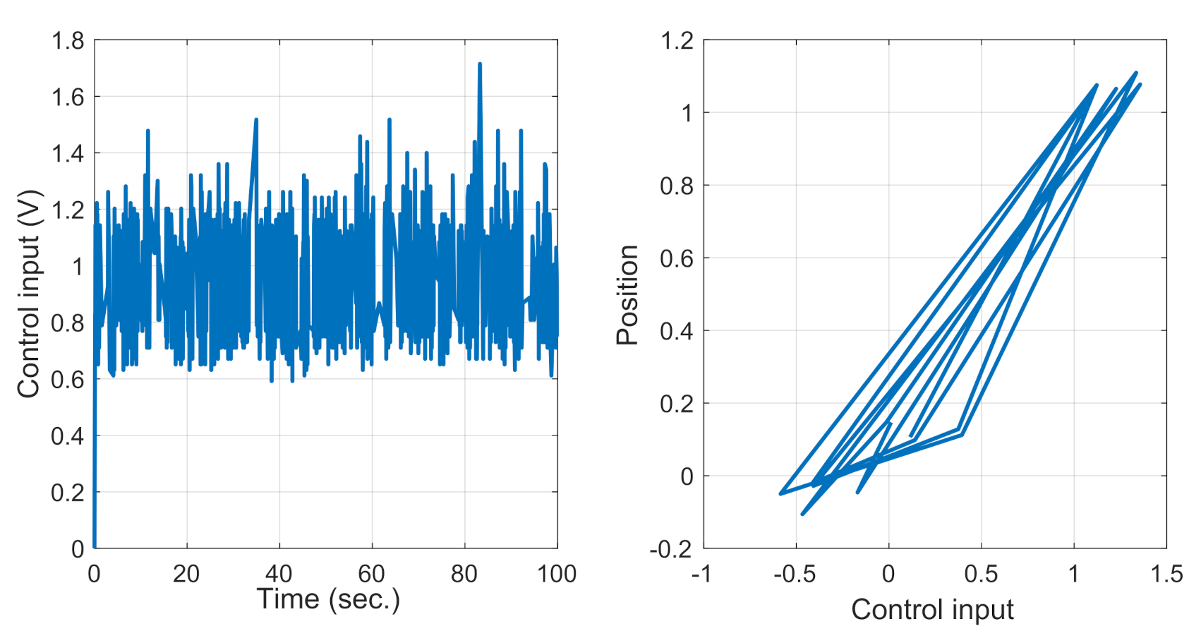
Figure 8.
Control effort and the corresponding hysteresis for the anti-windup control (8), along with Table 2.

Table 1.
Component list and cost calculation in EUR.
| Element | Specification | Price |
|---|---|---|
| Arduino Uno | ||
| Hall sensor | A1321 | |
| Object | Neodymium disc | |
| Capacitator | F | |
| Resistor | ||
| Diode | 1N5817 | |
| Transistor | NTD4858N | |
| Solenoid | 15 mH–2.4 | |
| Total |
Table 3.
Statistical mean absolute error corresponding to the control in the MagLev.
| (Error) | Value |
|---|---|
| Classical PID | |
| Control in (6) |
Publisher’s Note: MDPI stays neutral with regard to jurisdictional claims in published maps and institutional affiliations. |
© 2021 by the authors. Licensee MDPI, Basel, Switzerland. This article is an open access article distributed under the terms and conditions of the Creative Commons Attribution (CC BY) license (https://creativecommons.org/licenses/by/4.0/).
Share and Cite
MDPI and ACS Style
Pujol-Vázquez, G.; Vargas, A.N.; Mobayen, S.; Acho, L. Semi-Active Magnetic Levitation System for Education. Appl. Sci. 2021, 11, 5330. https://doi.org/10.3390/app11125330
AMA Style
Pujol-Vázquez G, Vargas AN, Mobayen S, Acho L. Semi-Active Magnetic Levitation System for Education. Applied Sciences. 2021; 11(12):5330. https://doi.org/10.3390/app11125330
Chicago/Turabian StylePujol-Vázquez, Gisela, Alessandro N. Vargas, Saleh Mobayen, and Leonardo Acho. 2021. "Semi-Active Magnetic Levitation System for Education" Applied Sciences 11, no. 12: 5330. https://doi.org/10.3390/app11125330
Note that from the first issue of 2016, this journal uses article numbers instead of page numbers. See further details here.