
A Novel Framework for Testing High-Speed Serial Interfaces in Multiprocessor Based Real-Time Embedded System

Department of Computer and Software Engineering, College of Electrical and Mechanical Engineering, National University of Sciences and Technology (NUST), Islamabad 44000, Pakistan
*
Author to whom correspondence should be addressed.
Appl. Sci. 2021, 11(16), 7465; https://doi.org/10.3390/app11167465
Submission received: 22 June 2021
/
Revised: 26 July 2021
/
Accepted: 4 August 2021
/
Published: 13 August 2021
(This article belongs to the Special Issue New Trends in Real-Time Embedded Systems)
Abstract
:Recent years has seen a tremendous increase in processing requirements of present-day embedded system applications. Embedded systems consist of multiple processing elements (PEs) connected to each other using different types of interfaces. Many complicated tasks are accomplished by embedded systems in varied settings, which may introduce errors during inter-processor communication. Testing such systems is tremendously difficult and challenging from testing non-real time systems. A major part of testing real time embedded systems involves ensuring accuracy and timing in synchronous inter-process communication More specifically, the synchronization and inter-processor communication of real-time applications makes testing a challenging task and due to the demand for higher data rate increases, day-by-day, making testing of such systems even more complex. This paper presents a novel frame work that uses multiple instances of simulators with physical high-speed serial interfaces to emulate any real time embedded system communication. The framework presents a testing technique that detects all faults related to synchronization of high-speed synchronous serial interfaces in a systematic manner. The novelty of our approach is to simulate communication across multiple processors in a simulation environment for detecting and localizing bugs. We verify this framework using a case study consisting of an embedded software defined radio (SDR) system. The test results show the applicability of our approach in fixing bugs that relates to synchronization issues that otherwise are very hard to find and fix in very complicated systems, such as SDR.
1. Introduction
Embedded systems are a combination of hardware and software that execute a particular task. Embedded systems usually have either a single task or a minimum number of associated tasks that they have been programmed to complete. These types of devices interrelate with the physical environments that they operate in. They are generally found in industrial, medical, automotive, commercial, and military applications. A real-time embedded system uses the features of both a real-time system and an embedded system. It is part of a larger device with a dedicated function managed by a real-time operating system (RTOS), and also has real-time computation and resource constraints. Their processing power and memory capacity are low relative to desktop computers, and the response time is among the most important key requirements. The design of real time system comprises task portioning, the selection of a proper language, and assigning and merging priorities using a real time scheduler to attain a response time. Reliance on scheduling goals, communication, and parallelism might be balanced [1].
In order to achieve a better performance, embedded system designers primarily focus on multi-core or multi-processor platforms [1,2]. A key concern in making multi core or multi-processor computing systems is how to use the available computing resources most efficiently. There are two types of constraints encountered by tasks executed in a real-time embedded environment, i.e., resource constraints and time constraints. The response time is used as an effective indicator of time constraint requirements [3]. Various applications operating on a system on a chip (SoC) typically cause timing interference, making it difficult to conform to real-time response requirements [4]. These devices are intended to satisfy the strict embedded application requirements, which demand real-time responses. A vast number of methods, tools, techniques, and strategies are used for timing analysis, scheduling, and improving timing predictability. Still, there is no such thing as a one-size-fits-all fix [2].
A real-time embedded system with several processing elements (PEs), connected via different physical interfaces, establishes a communication link between them using inter-processor communications (IPC) [5]. While efficient and fast inter-processor communications remain the key factor in accomplishing successful real-time simulation [3], often, in real-time, the synchronization and inter-processor communication become the most significant factors affecting the performance. Simulation-based techniques for testing embedded systems have been in use for hardware modeling, as well as system software design, with technologies maturing over decades [6]. Simulation provides an insight into systems that may not be evident through other testing techniques. However, the simulation environments are still unable to fully mimic inter-processor communication in general and for synchronous interfaces in particular. This is due to the time constraints when the processors are using a real-time operating system where switching between multiple interfaces may introduce more time delays during transition or processing of new interface, it makes simulation an even more challenging task [7]. Hence, emulating high-speed interfaces to mimic real-time situations is practically impossible and is not perfectly controllable, as in the case of hardware or processor simulations. Therefore, there is a considerable potential for research in this area to investigate means for testing inter-processor communication in real-time environments.
This work aims to address the challenging task of testing high-speed serial interfaces that require debugging in real time while an application runs since there are several factors affecting inter-processor communication, such as computational complexity of real-time algorithms that are running or the type of real-time operating system, etc. As the requirement for high data-transfer rates grows, it is much more critical now to test and validate these interfaces [8]. In particular, this work focuses on testing the application with high-speed serial interfaces. The work is motivated by the experience of developing complex multiprocessor-based embedded system where the most challenging aspect of the implementation remains the testing and debugging of high-speed synchronous serial interfaces with multiple seen or unseen factors affecting the communication. Real-time embedded systems face these types of problems in many domains, such as in radar applications [9], ultrasound systems [10], software-defined radios [11], automotive electronic control unit applications [12], etc., where high-speed processing is required in a real time system. Our novel framework is based on the methodology of creating a knowledge base through simulation. This knowledge base is then used for direct identification or zeroing of bugs that may arise due to issues of timing and synchronization of the interfaces. We applied the framework to SDR for testing. The case study results are presented, showing the testing using a multi-instance simulator. The results show the appropriateness of our approach for finding and repairing bugs that are otherwise quite difficult to identify and correct.
The rest of this paper is organized in the following manner. An overview of high-speed interfaces and related work is presented in Section 2. The proposed framework and implementation details are discussed in Section 3. In Section 4, we present the results and explain the validity of the approach. We explain the SDR case study in detail in Section 5. Section 6 presents the discussion. Lastly, Section 7 concludes the paper.
2. High-Speed Interface Overview and Related Works
Data transmission and reception between PEs and their peripherals are accomplished via communication interfaces [13]. With rising data-rate requirements and ramping up integration density posing new design difficulties at the chip, circuit, and system levels [14], and the resulting gap due to high data rates in the bandwidth of the PEs and peripherals has become a key barrier for the entire system performance [15]. The need for greater bandwidth interfaces in computing systems has resulted in the increased use of high-speed communication interfaces [16]. High-speed interfaces are key components of any electrical design and have become a cornerstone for communication [17]. High-speed serial interface devices are becoming widely used in communications, ranging from embedded to high-performance systems, as well as from on-chip and massive haul [18]. Due to the need for high-speed data processing, the data transmission speed of these interfaces has been steadily increasing [19,20]. Although, in the past, the parallel approach was the most commonly used for high-speed communication, this is no longer the case. The decreased cost of integrated circuits, along with growing consumer demands for faster and longer distances, has led to the serialization of parallel connections [21]. A high-speed synchronous serial interface is a high-speed communication interface. It is a low-latency, full-duplex protocol designed for die-level interconnection between a baseband chipset and an application processor. It was developed by the MIPI alliance in 2003 and has been deployed by a number of vendors since then. It is the predecessor of mobile phone inter-chip interconnects and can still be found on many modern SoCs [22]. Some interfaces rely on clock forwarding, often known as source synchronous timing. The testing difficulties connected with this technology are substantial [23].
The debugging, and testing of these types of interfaces is becoming highly difficult as design complexity rises and the time budget tightens [24]; it and has also been a critical issue due to additional test times, signal integrity problems, and the use of costly instrumentation [25,26,27]. As the requirements for higher data transfer rates grow [28], it is much more critical to test and validate these interfaces during development [29]. However, testing such interfaces usually requires the use of specialized test equipment and software, or it needs to be outsourced to external providers. These systems often provide interface compliance testing and are expensive and are normally unnecessary during prototype development [30]. Typically, these external providers only provide full interface compliance testing. This method is time-consuming and is frequently unneeded for embedded systems that do not require interfacing for general-purpose hardware [31]. Both academics and industry are continuously striving to develop new ways to debug and test these interfaces due to the constantly increasing data rates and to design the complexity of embedded systems. Our proposed framework tests these interfaces in a multiprocessor-based embedded system.
Moreira and Werkmann [32] also discussed the use of automated test equipment (ATE) and external measuring devices to characterize and test high-speed I/O digital interfaces. The difficulties that the test engineers face with high-speed devices were also addressed. They provided hardware-testing solution ATEs and focused on production testing based on functional/specification testing. Fan and Zilic [33] proposed a subtle approach for validating, testing, and debugging high-speed serial interfaces. They utilized an approach that can also self-calibrate and diagnose. Some of the existing ATE restrictions also addressed with the external loopback method. They evaluated and tested high speed interfaces without the use of high-speed ATE instruments or design for-test (DfT) functionalities using a new jitter injection method and an FPGA-based bit error rate tester (BERT); this approach also solves conventional ATE instrument constraints. They intended to employ ATE high-speed instruments or do external loopback testing without ATE, depending upon on the applications. They used electronic test equipment BERT for post-silicon validation acceleration and focused on functional testing and high-speed serial interfaces. Abdennadher and Meixner [34] concentrated on testing that looked for manufacturing circuit-level flaws that may affect system performance. They discussed the distinctions and provided a summary of twenty years of defect-based testing experience with high-speed I/O interfaces. These findings indicated that defect-based testing approaches based on DfT circuits may cover the same erroneous behaviors as specification-based testing. They also examined and recommended solutions to bridge potential gaps that infrequently used high-speed I/O defect-based test techniques. They ensured that the performance of high-speed I/O interfaces necessitated rigorous production testing, either using defect-based or specification-based methods.
Abdennadher and Shaikh [35] presented a review of industry practices of the approaches based on DFT to testing high-speed IO interfaces, as well as a comparison of these approaches to specification-based testing. They discussed DfT, which assesses device performance in five areas: transmitter with functional speed, transmitter implied jitter production, receiver with functional speed, receiver minimum detectable level, and receiver jitter tolerance. Fan and Zilic [36] proposed a BERT method to describe the quality of communication interfaces. They introduced a BER tester core and a unique additive white Gaussian noise (AWGN) generating core for BERT in field-programmable gate arrays (FPGAs). In terms of cost, volume, and energy, combining a BERT with an AWGN in FPGAs is orders of magnitude more efficient than existing similar-speed stand-alone systems and has a large speed advantage over software simulations. The whole BERT method can be used to test and evaluate the performance of a variety of communication devices, including spread spectrum, user-defined modulation, native clock/data recovery interfaces, and error-correcting codes. They validated their proposed solution via two case studies: one evaluating an AWGN baseband transmission system and the other testing a high-speed serial interface. They used electronic test equipment BERT and focused on the functional correctness of high-speed serial interface transceivers. Arora and Jaliminche [37] proposed creating a DMA controller and a high-speed synchronous serial interface test harness. This suggested that the test harness may be used to stimulate the device under various test capabilities, as well as for behavioral analysis. They created test drivers that can be used for testing by incorporating appropriate observability characteristics. To evaluate the success of this test harness, the experimental results are supplied with appropriate functional test coverage.
Shen [38] presented case studies of external loopback, which is one of the most often used DfT approaches for high-speed serial interface testing. They briefly discussed the various types of loopbacks that are accessible in the industry, along with their applications. Following that, the importance of external loopback interactions in the high-speed serial interface test method was discussed. The external loopback circuitry on the device-under-test (DUT) card was then explained, followed by test techniques for enabling high-speed serial interface buffer level testing that was implemented on transceiver-based FPGA products. They also provided a review of silicon experiences, as well as recommendations for future developments.
All prior attempts have proposed to test high-speed serial interfaces through electronic equipment and provide specification-based testing or defect-based testing. Our proposed approach directly identifies or zeroes synchronization bugs, which is primarily not a functional bug but is a bug caused by the timing and synchronization of high-speed interfaces. Considering the challenges still to be experienced in an embedded system and the need to develop specialized and efficient approaches for testing high-speed synchronous serial interfaces where these interfaces are for debugging while the application is running during development. This paper proposes a novel framework for testing high-speed serial interfaces in a multi-processor-based real-time embedded system by developing a knowledge base through simulations that are capable of detecting and localizing synchronization bugs in inter-processor communication.
3. The Proposed Framework for Testing
The proposed framework considers an embedded system with multiple PEs connected to each other using different types of interfaces. In this framework, the communication across multiple processors is simulated using multi simulators for detecting and localizing bugs.
We assume that there are n numbers of processors connected in an embedded system. These processors communicate with each other through high-speed physical synchronous interfaces. All individual segments of the embedded system have been functionally tested for their correctness. When these PEs start to communicate with each other using the high-speed synchronous interfaces, synchronization errors start occurring. These errors can occur, not due to the functionality of a specific PE, but rather due to inter-PE communication. To narrow down the specific interface that has malfunctioned, we generated a ramp continuously, as it is the easiest signal to identify for any errors occurring in a system, and found the outputs at each interface through the emulator in order to record their outputs. These outputs are used to narrow down and identify the specific interface causing errors. Depending on different scenarios, a different interface can malfunction. Test data are generated which accommodate all scenarios in multiple interfaces to check whether the communication happens with or without any synchronization issues and the results are used to generate the knowledge base. The test data are then provided to the simulators. For the cases where there is a specific problem, the scenario is saved in a database that acts as a knowledge base. A typical approach for creating test cases from the use cases is scenario analysis. Use cases are a useful tool when developing test cases for a system.
Firstly, we generated test cases through use case scenarios where the communications at different links happened in a synchronization sink. At a few links there were also synchronization issues. This allowed us to generate all possible perceivable results. Several synchronization bugs were identified in inter-processor communication. These bugs were simulated in MATLAB. Simulation of these bugs helps in building a knowledge base. The knowledge base contains test cases, synchronization bugs, and simulated waveforms of the synchronization bugs.
Once the actual testing is done on the actual system through emulators and in the case where the expected results do not match, then a comparison is done with the results stored in the knowledge base. Then, correlations between the actual and simulated results are computed. We compared incoming waveforms of high-speed interfaces with the stored simulated synchronization bugs’ waveforms from the knowledge base. The closest correlation is matched with the specific use case of a communication system.
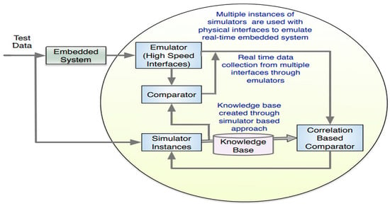
Synchronization failure is automatically extracted from the database and is then used to localize bugs. Figure 1 explains the proposed framework for testing a real-time embedded system.
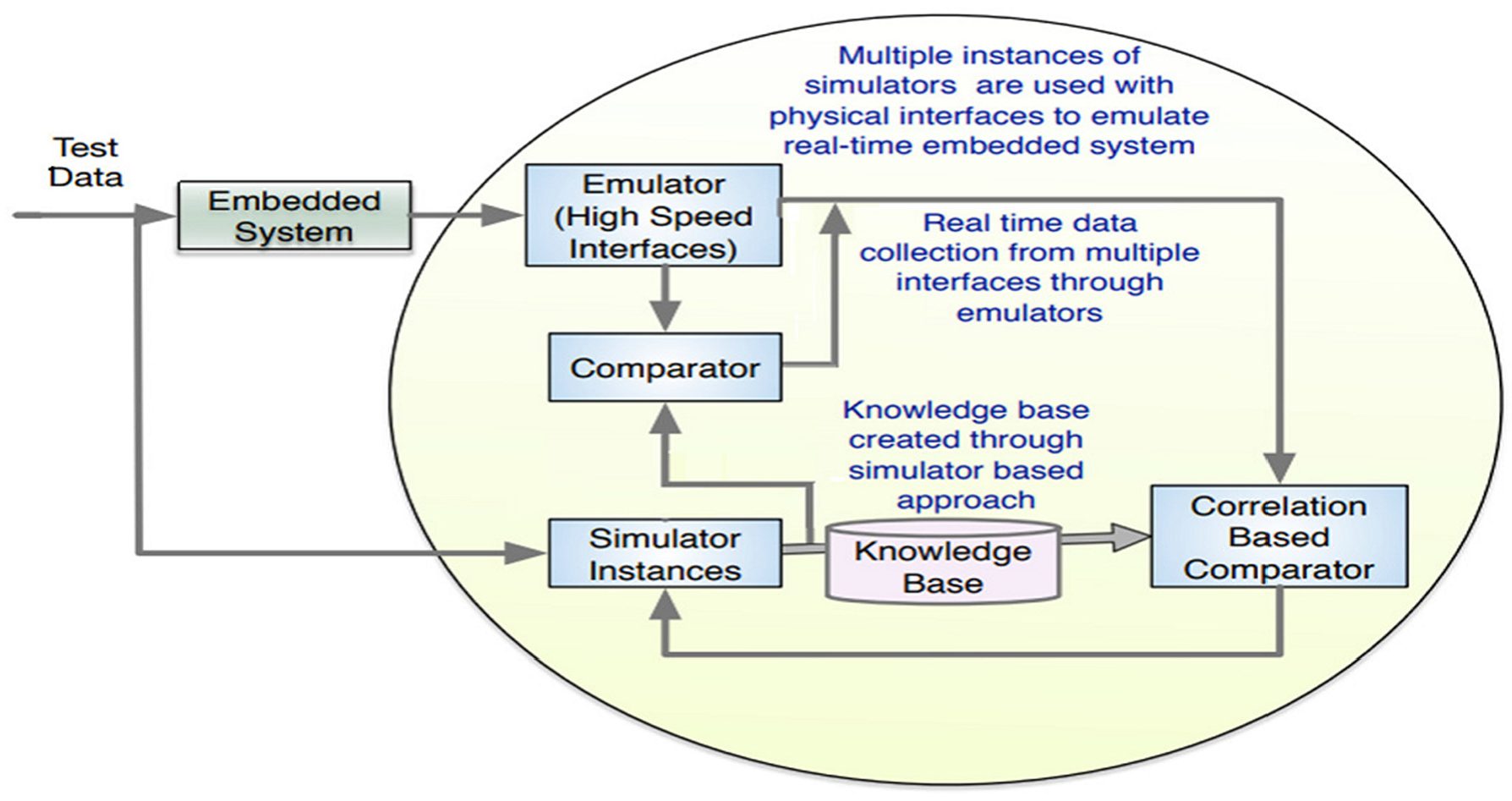
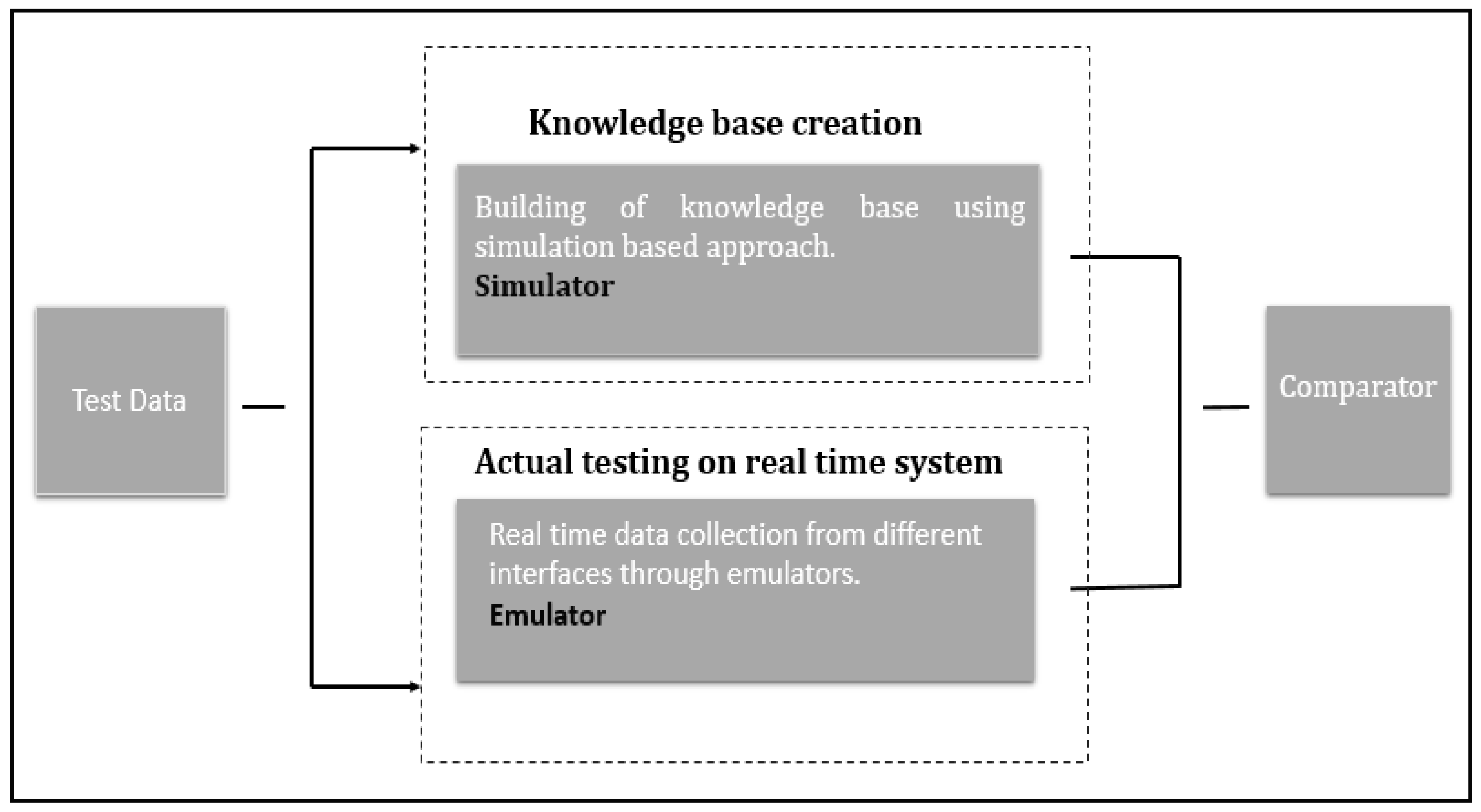
The first step of the proposed framework was the creation of a knowledge base through simulations and the second step was to capture data using emulators and test the actual system, shown in Figure 2.
3.1. Simulator Architecture
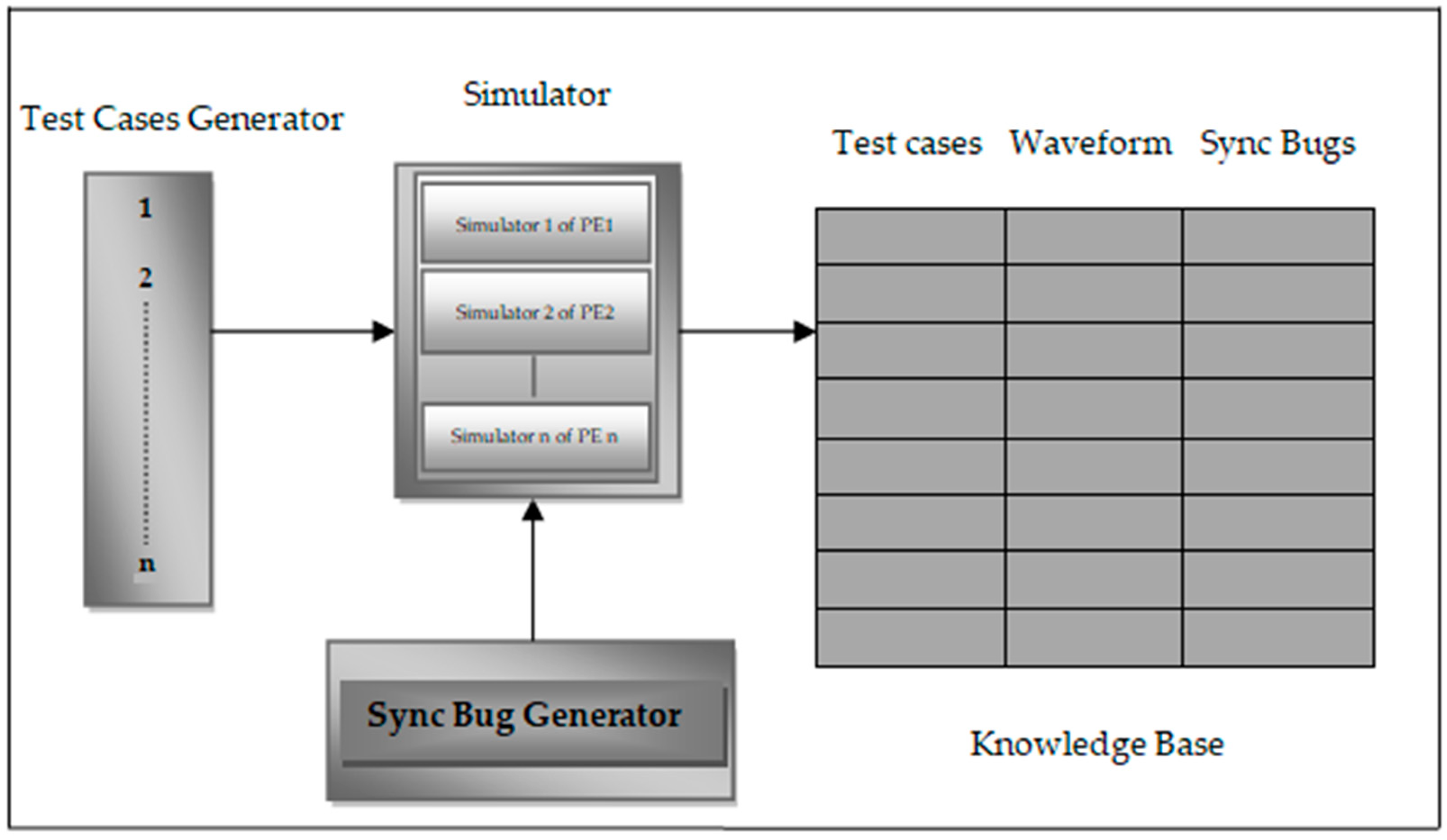
The simulator consists of three distinct parts: the test case generator, the simulator that simulates the different processing elements of a multiprocessor embedded system using instances of simulators, and the sync (synchronization) bug generator.
The test case generator generates test data that will be input into the embedded system simulator. Several synchronization bugs, as described in Section 3.1.2, were induced by us into the interfaces because there are an unknown set of bugs that usually happen in these high-speed interfaces. The synchronization bug generator will generate these synchronization bugs. Based on the specific test case and the generated synchronization bugs, the simulator will generate the outputs of each specific bug. These simulated input test data, specific synchronization bugs, and the generated output waveforms are stored in the knowledge base.
All these synchronization bugs are simulated using MATLAB code. With the aid of simulations, we generated all possible perceivable results in the knowledge base. Figure 3 shows the proposed architecture of the simulator that is used for building the knowledge base.
3.1.1. Multiple Simulator Instances
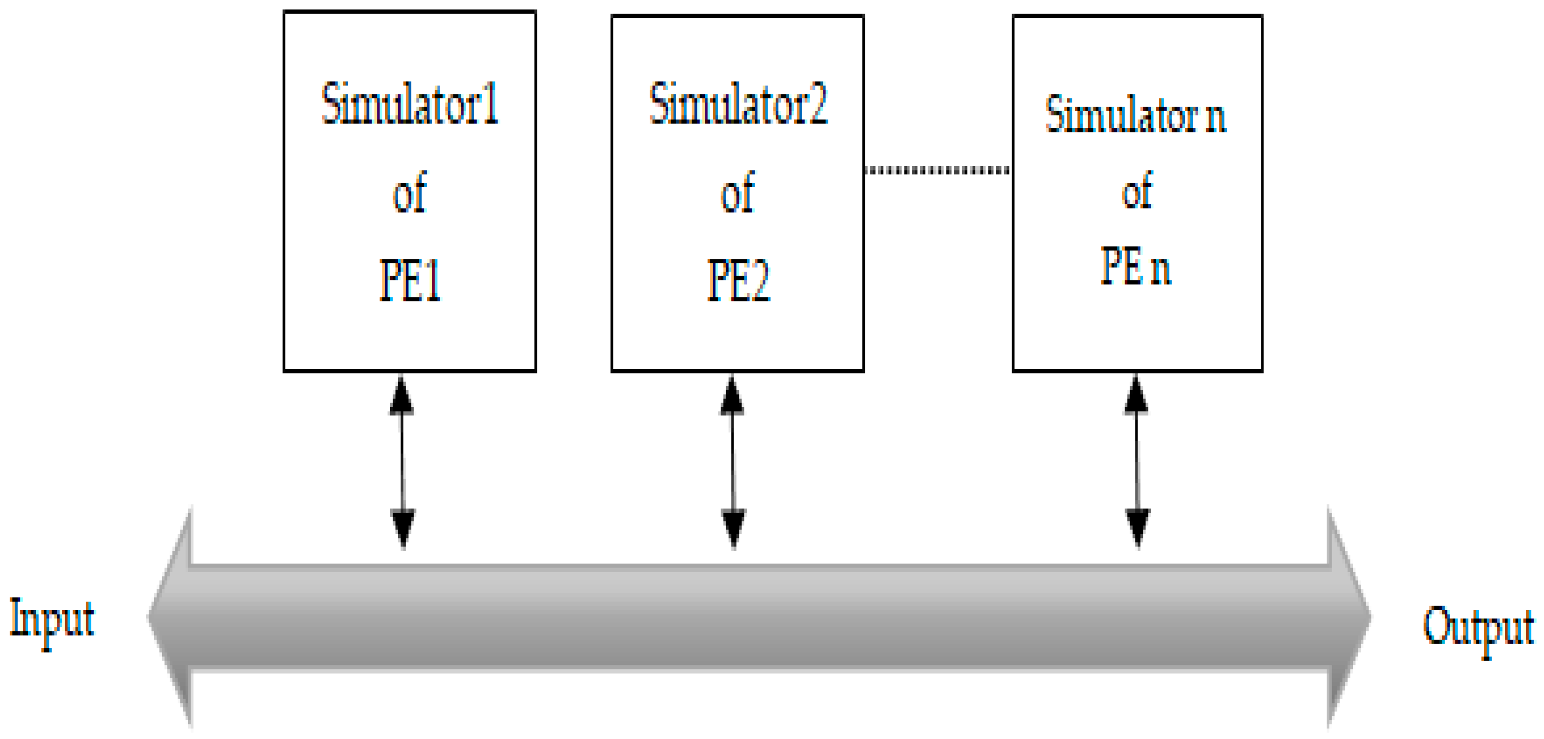
A multi-simulators approach with real-time embedded system counterparts is helpful for embedded testing. The outcome of simulations helps in understanding the communication system’s challenges [39]. Communication across multiple PEs are simulated on multi simulators. Multiple instances of the same program are running in the same MATLAB.
Each instance of the simulator is connected to a separate processing element. These instances of simulators are developed in MATLAB to simulate inter-processor communication for testing the embedded system. In this way, the complete system was simulated with only high-speed synchronous serial interfaces, where PEs did not perform any processing, and only sent whatever was received from one high-speed synchronous serial interface to another. Figure 4 explains that multiple instances of simulators are created across multiple PEs. Several synchronization bugs were induced using MATLAB.
3.1.2. Sync Bug Generator
Loss of packet or data during inter-processor communication in embedded systems takes place due to timing and synchronization issues, i.e., “breaking–up” of voice and video communication, extensive buffering, and skipped videos. When scenario like data loss, or when it is not received in order, occur during communications then lost data will need to be retransmitted or reordered during a particular communication.
The sync bug generator generated all possible synchronization bugs that occur during inter-processor communications that are shown in Table 1. These bugs are further reported in [40] and were simulated through a simulator and stored in the knowledge base. These are primarily not functional bugs, but rather bugs created by the interfaces’ timing and synchronization.
The explanation of each bug is as follows:
- Data received at Rx with delay: delay occurs in receiving data at Rx. Delay can occur at various points during communication, such as at the beginning, in the middle (anywhere between communication), or both.
- Data transmission from Tx with delay: delay occurs in transmitting data from Tx.
- No data received at Rx: Tx sends the data constantly but Rx does not receive it.
- No data transmitted from Tx: Tx does not send the data to Rx.
- Data overriding during communication: Rx overrides some packets of data during communication.
- Out of synchronization: data are not received in a sequence (out of order).
3.1.3. Scenario Based Approach for Test Cases Generator
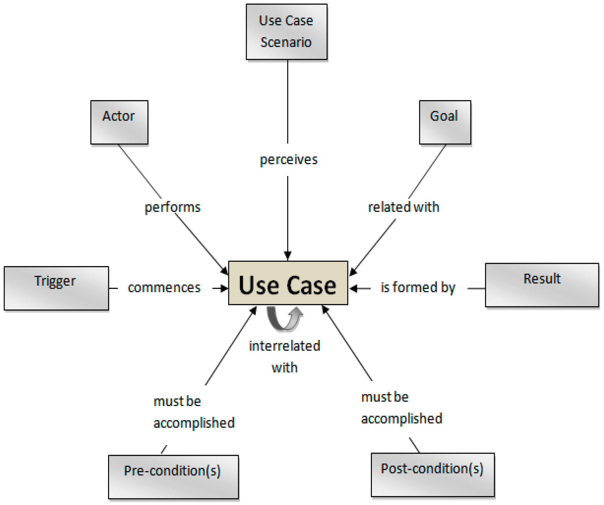
A scenario is an explanation of an actual or imaginable act and sequence of events resulting in a particular act [41]. Scenarios specify user requirements. In addition, they are also used to discover and explain system behavior. With reference to scenarios, a use case can be viewed as a general form of explanation for a set of tangible scenarios. Specifically, we adopt a scenario-based approach to describe test cases in our framework. The use case model that we used for the scenario-based approach is shown in Figure 5.
Use cases can be interconnected with other use cases. Figure 5 also shows the use case attributes. Because use cases act as the standard type explanation for the related scenarios, every scenario inherits the attributes described for its use case, for example trigger, goal, precondition, post condition, etc.
To observe the bugs shown in Table 1, various use cases were developed. Use cases illustrated the simulation scenarios where the communication results were examined. Use cases were defined on a deeper level by specifying scenarios. We generated test data based on the possible scenarios of all physical interfaces. The data received at Rx with the delay scenario written as a use case is shown in Table 2. It shows the template for “data received at Rx with start delay” scenario. The template provides comprehensive steps of events to identify bugs through simulation [42,43,44].
Different test cases were generated using case scenarios of all interfaces, where the communications at different links occur. One-to-one correspondence was used between the use case and the test case. A test case is a collection of several actual tests, while a use case is a collection of several scenarios. Essentially, each test was a refined corresponding scenario. The scenarios related to the use cases were much more general and were most often described informally.
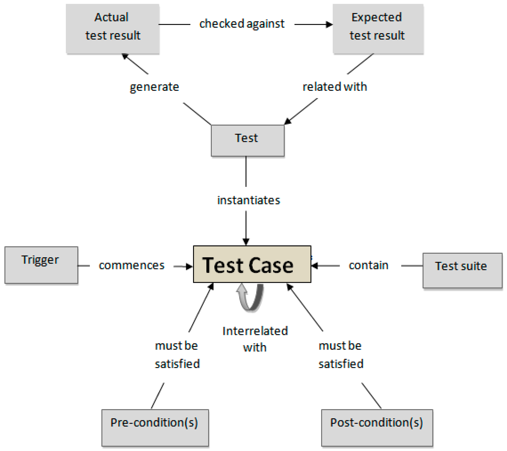
A test case may be initiated by a certain event or action, known as a trigger. While it is the same trigger as described in the subsequent use case, it is represented in a formalized way in a test case.
Conversely, both test pre-condition(s) and test post-condition(s) were formulated and the improved form of the respective conditions was specified as in respective use case. The test case model that was used for testing in the proposed framework is shown in Figure 6.
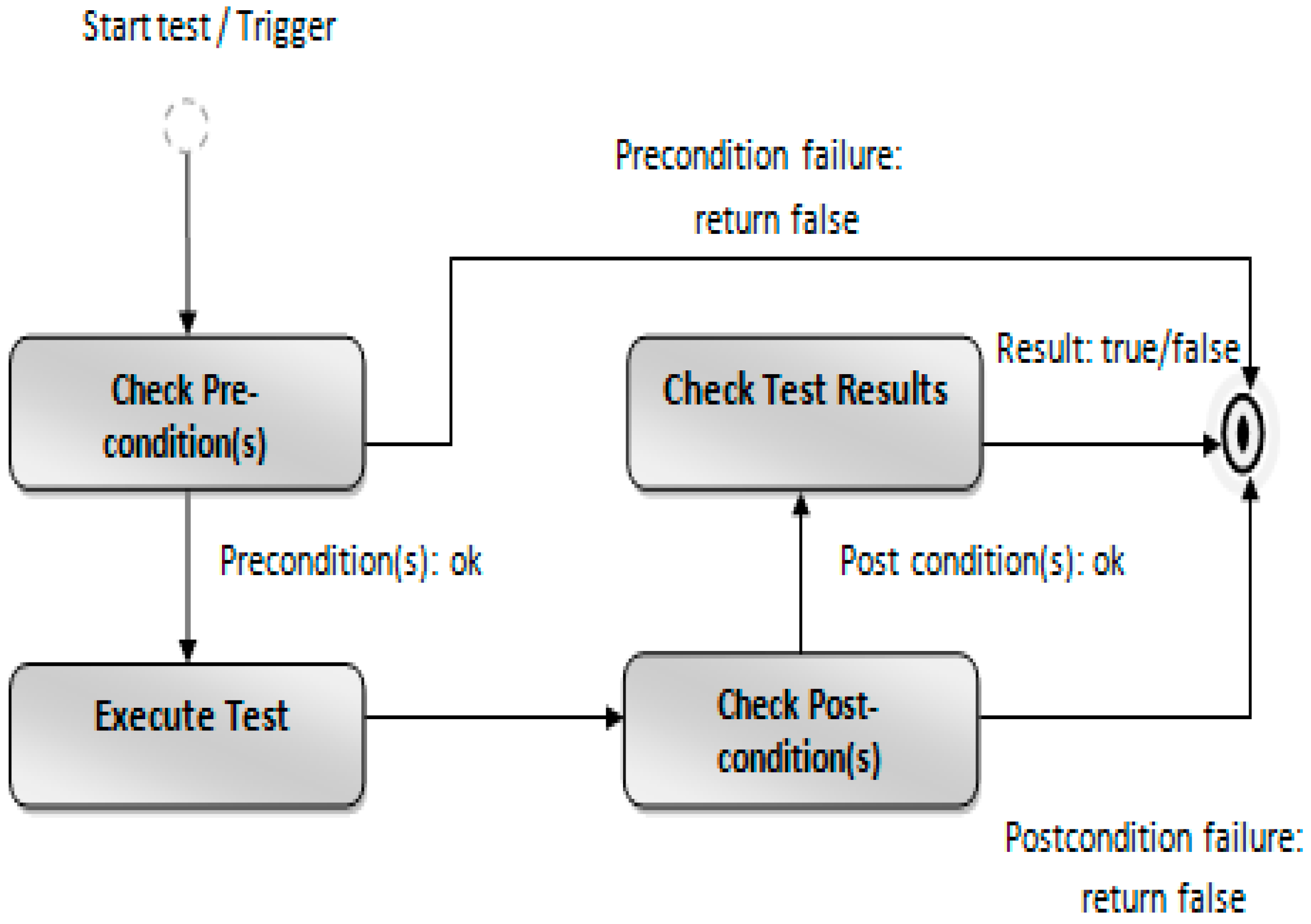
A group of test cases is called a test suite. The test case for “data received at Rx with start delay” is shown in Table 3. While performing the test, the normal flow of events in the proposed framework is represented in Figure 7 as an activity diagram. All the test preconditions must be checked when the trigger event of the corresponding test case takes place. One of the tests related to this particular test case is performed if all the preconditions are satisfied.
After performing a certain test, we then checked if all test post conditions were met. During a particular test run, it was checked whether the actual results produced matched the expected results for the test or not.
Test cases for Tx are shown in Table 4. The remaining test cases of Table 3 and Table 4 are provided in Appendix A.1 and Appendix A.2. The scenarios for the use cases are used to generate these test cases.
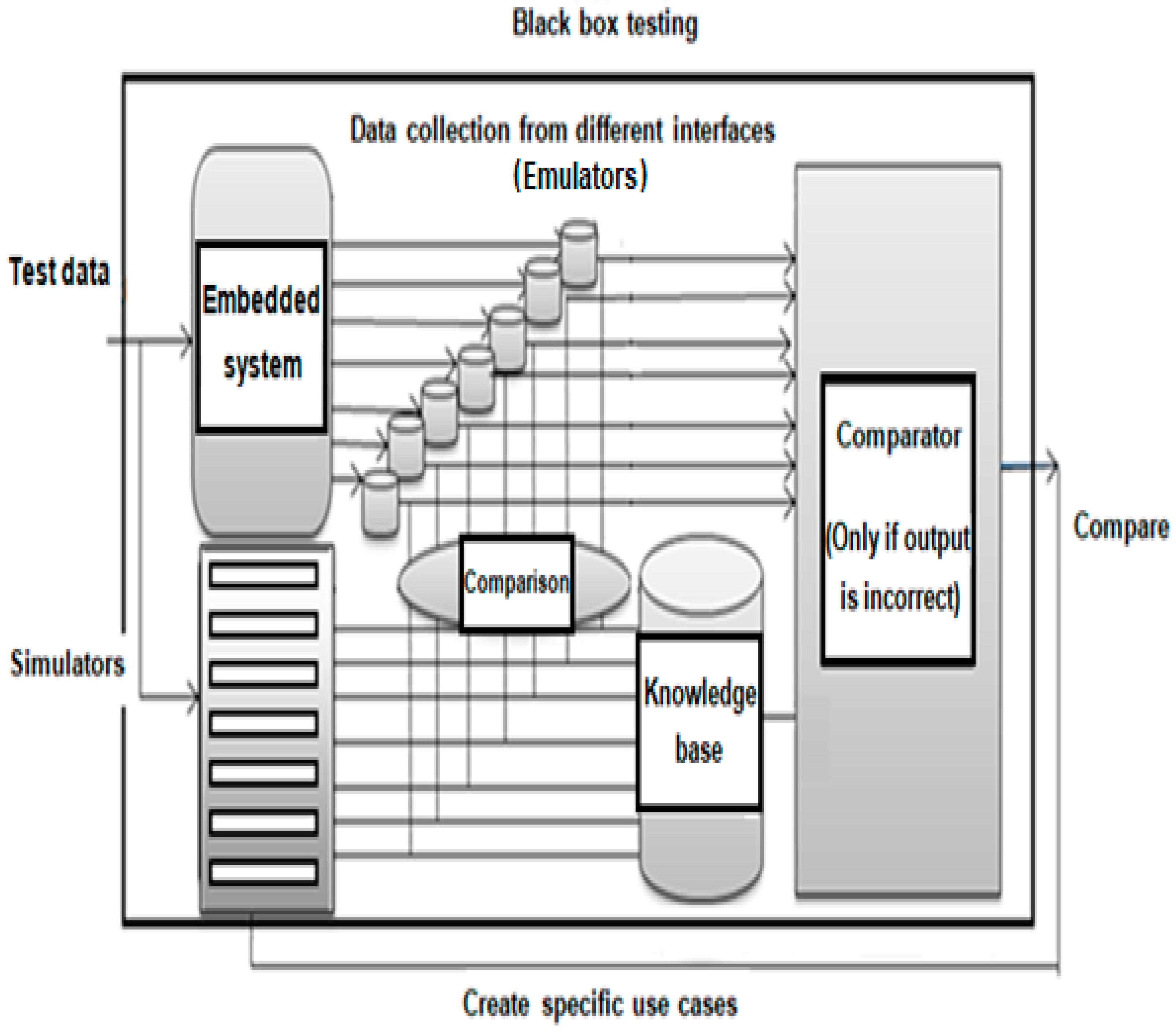
3.2. High Speed Serial Interface Testing
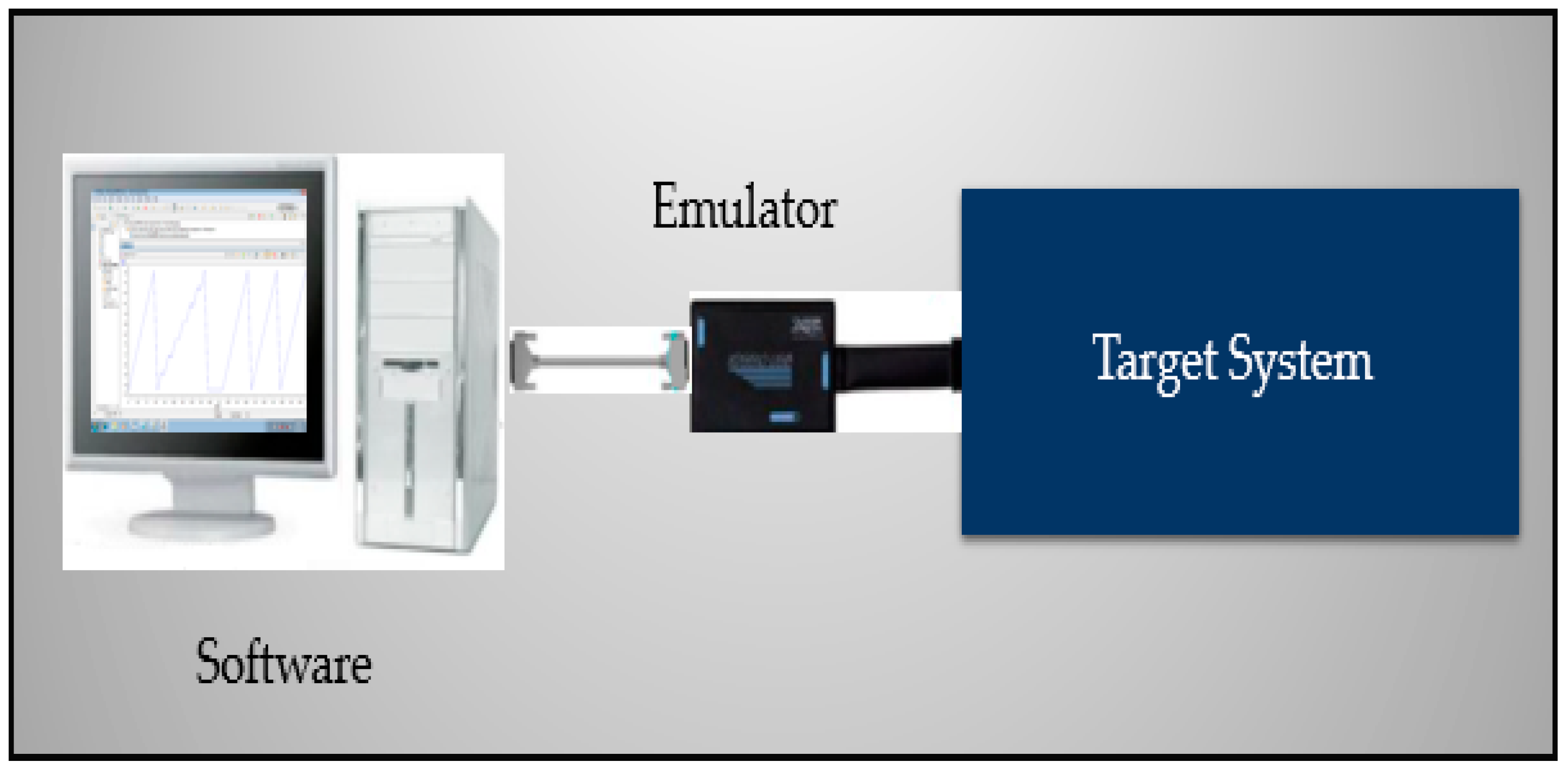
Emulators have long been used by hardware and software engineers to emulate the behavior of complicated circuit building blocks and enable hardware and software diagnostics and debugging (shown in Figure 8). An emulator is a hardware device or software program that has been used to capture real-time data in a proposed framework.
Emulation is presently most often used to examine and diagnose the behavior of sophisticated devices that have internal architectures that are much too complicated to be easily modeled by computer simulation software.
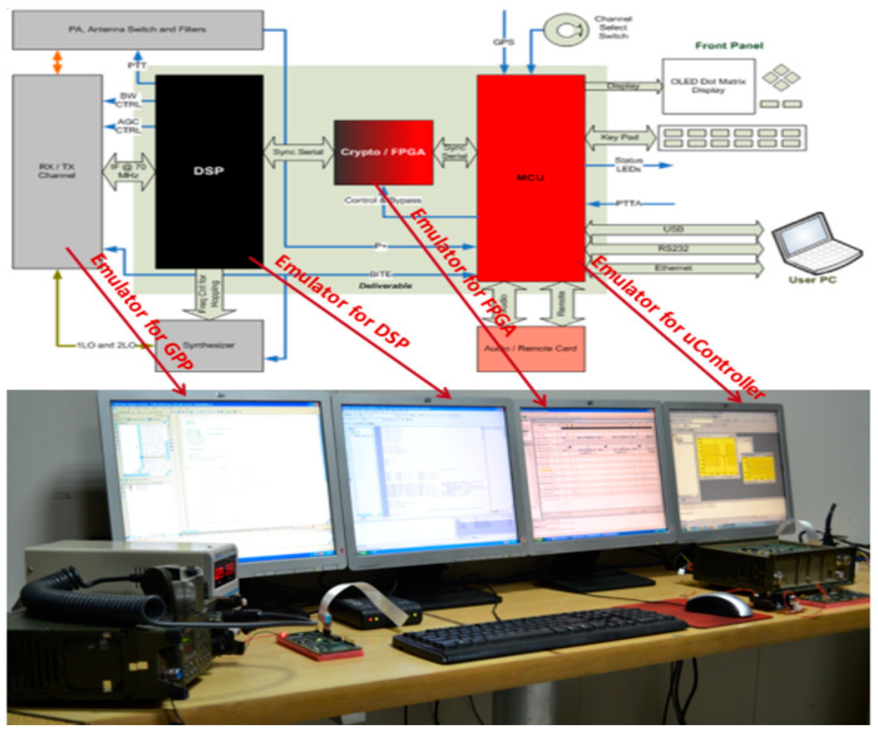
In the proposed approach, each emulator was connected to a processor using a different computer. Several emulators were used with interfaces that captured real-time data. A ramp signal was sent as the input from one processor to another. The ramp signal was the best signal to test these interfaces. It contained values that provided visual indications of any bug that may arise during inter-processor communication and to understand dynamic system behavior through the velocity factor. Real-time data of every PEs were captured using emulators, shown in Figure 9. This identified the incorrect ramp waveform and then compared it with a knowledge base. In this way, the complete system was emulated at the same time.
In this case, the expected results of different PEs interfaces did not match the actual results; then, the proposed framework compares the actual results to the stored results of the knowledge base and computes the similarities between them. The most closely related correlation is then matched to the specific use case. As a result, the proposed framework extracts and localizes the bugs automatically.
4. Simulation Results
This section describes the simulation results stored in the knowledge base for testing the real-time embedded system and provides the test validation of the proposed framework. The instances of simulators were developed in MATLAB to simulate the synchronization bugs that were stored in the knowledge base.
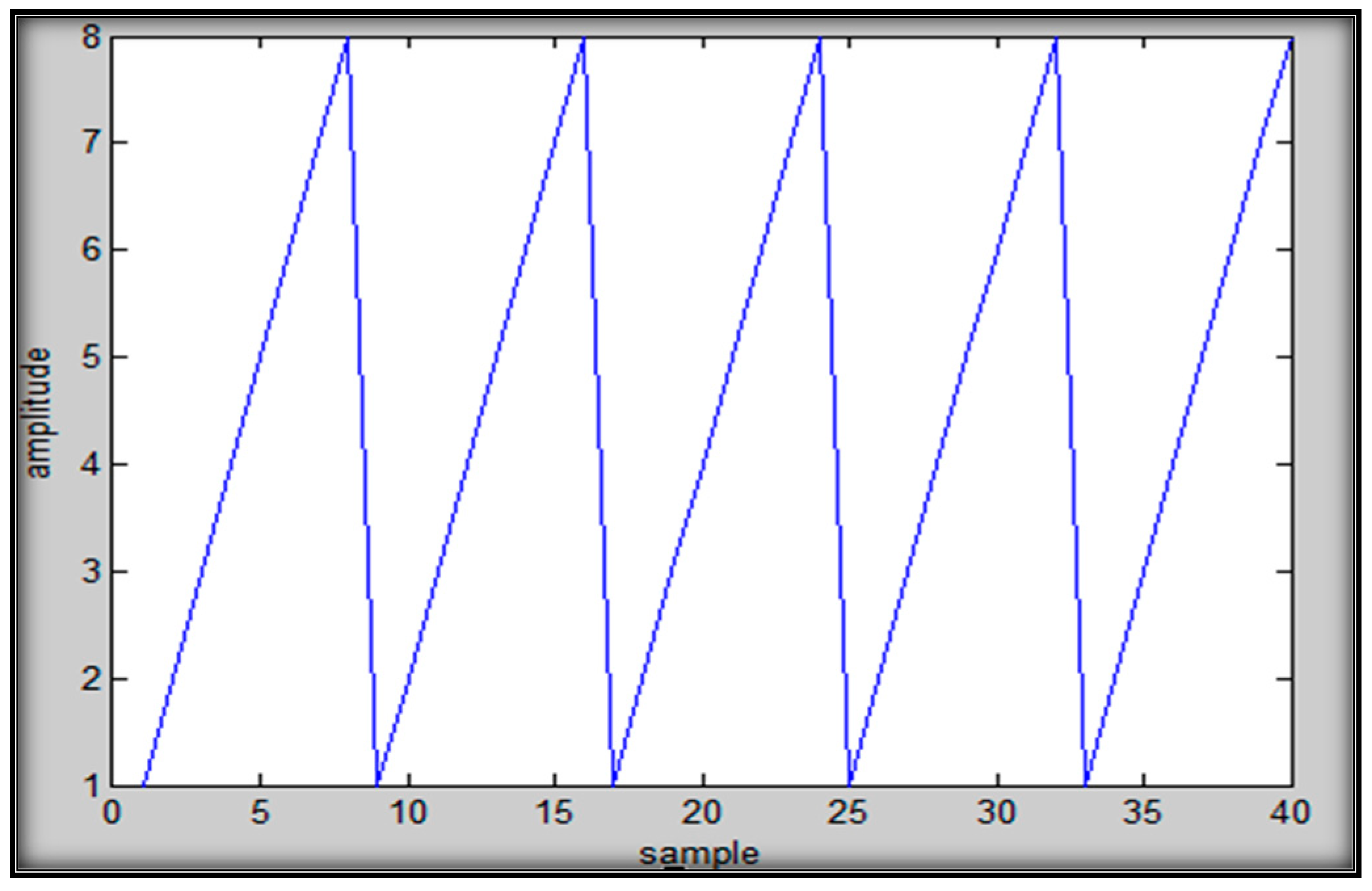
Tx sends the data continually and Rx receives the without any disruption. This is the ideal case for communication. Figure 10 shows the simulation results of the normal correspondence between Tx and Rx.
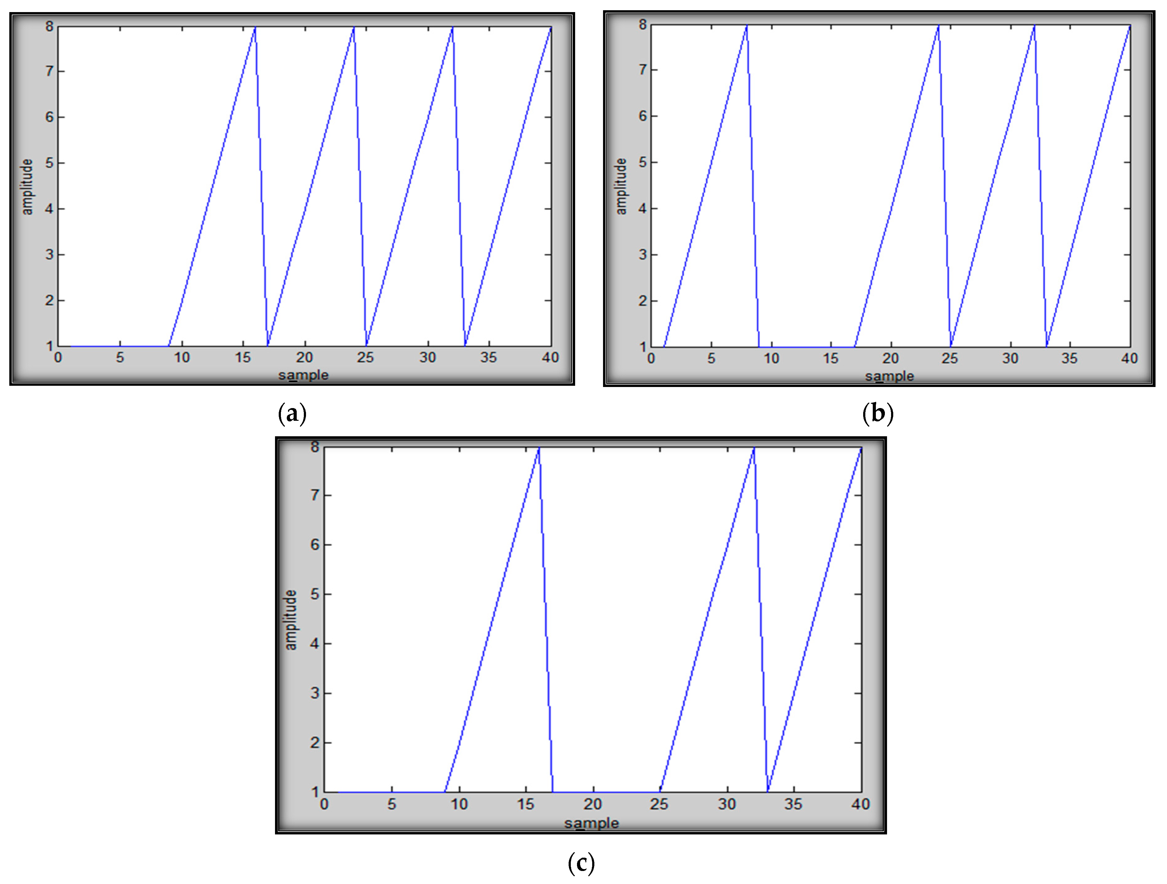
Delay refers to the time required for data to be transmitted from one processor to another. Communication delays can influence the performance of an embedded system overall. Delay can occur at the beginning, anywhere in the middle, and in both cases during the communication from Tx to Rx, shown in Figure 11.
Figure 12 shows the results of simulations where the transmitter is sending the data continuously while the receiver is not receiving the data due to some fault in the communication system.
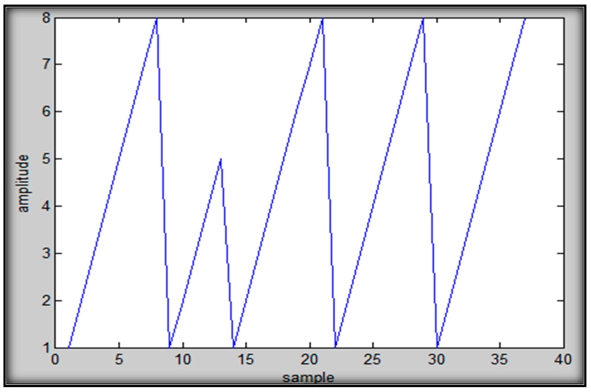
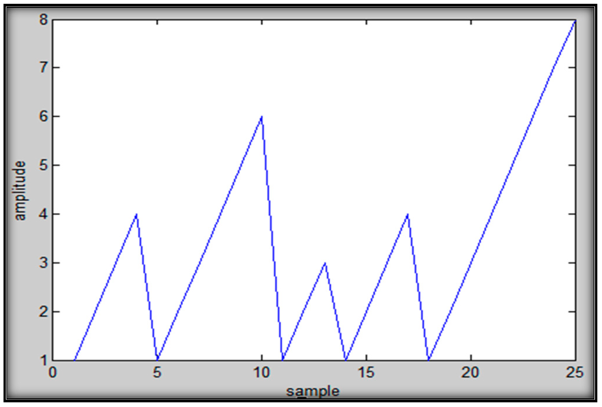
Tx does not send data so Rx is unable to receives any data. Figure 13 shows the scenario where Tx does not send the data to the receiver (Rx). Figure 14 shows that Tx sends the data continuously but Rx overrides some packets of data during communication (i.e., the 3rd packet of data overrides the 2nd packet of data), as detailed in Table A1. Figure 15 shows that data are not received in a sequence (out of harmony). Such data loss can happen in real-time systems when one or more packets of data fail to reach their destination.
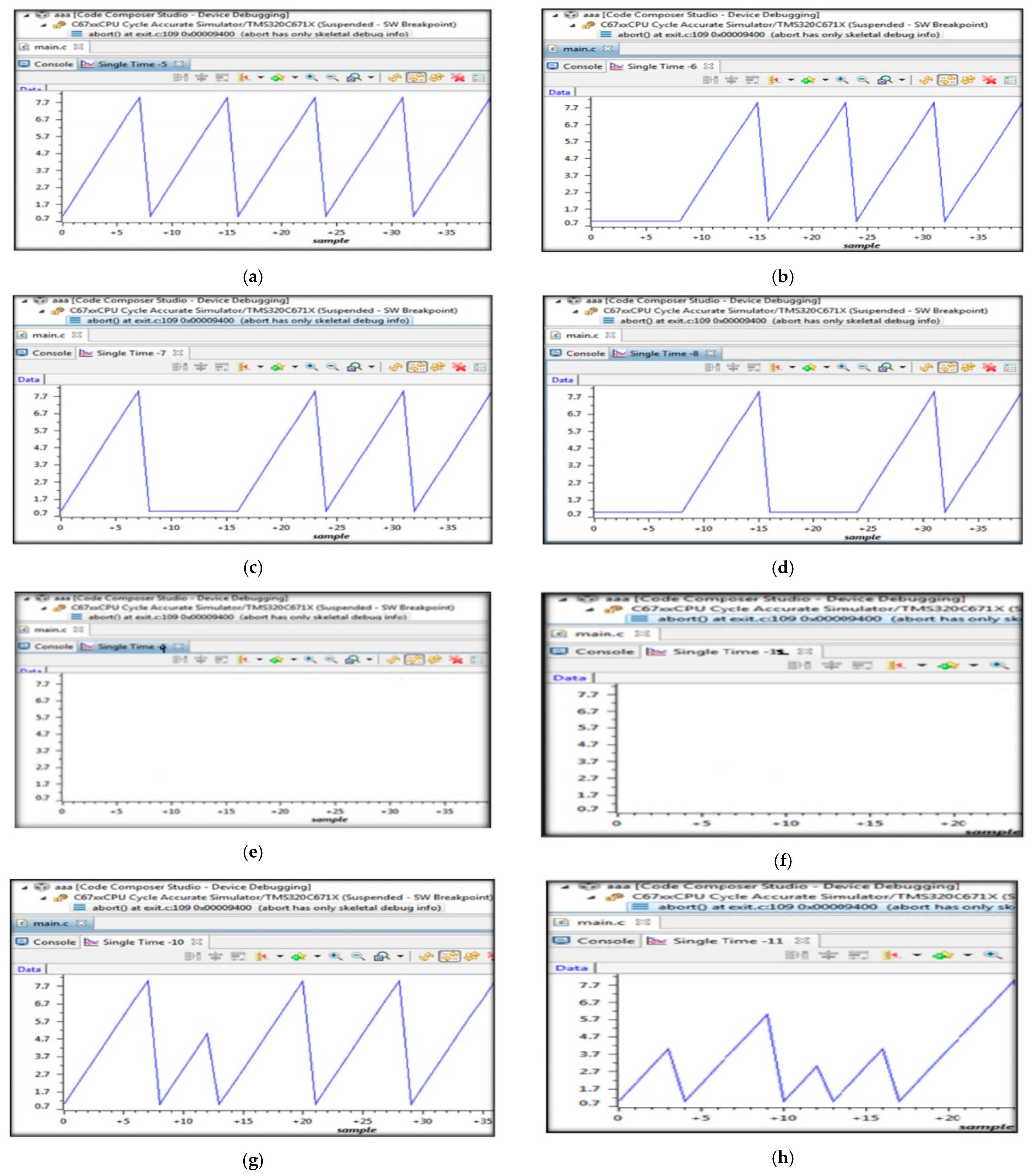
Synchronization bugs were also simulated in code composer studio software to validate the proposed approach. The results are shown in Figure 16.
Test Validity
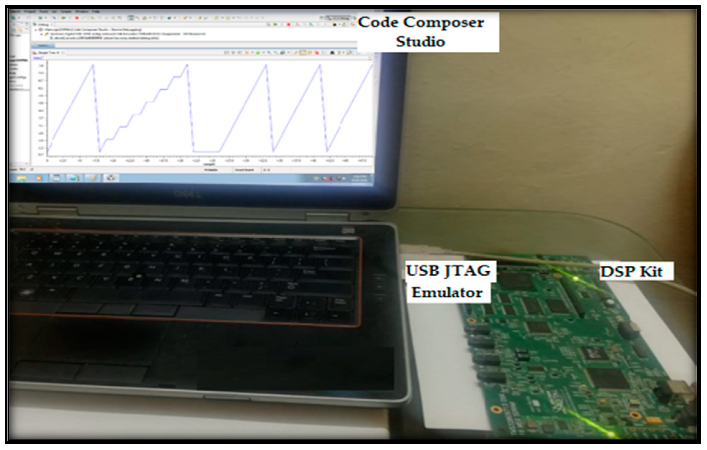
The USB JTAG emulator allows for high-speed data transfer and is used to interface with the DSP kit. It establishes a unified way for connecting development tool software to a DSP target system, which was one of the Pes.
To validate our approach, we injected a synchronization bug in the digital signal processor (DSP) kit, shown in Figure 17, and then compared it with the results stored in the knowledge base.
The proposed approach is capable of detecting and localizing the timing and synchronization bugs that occur in any high-speed synchronous serial interface during inter-processor communication in a real-time embedded system.
5. Case Study Settings
To test our proposed framework, a wireless communication-based SDR embedded system was used. To cater to the complexity of several components of an SDR, the proposed framework used several simulator instances with physical interfaces to simulate SDR-embedded wireless communication systems. The effectiveness of the framework was measured by detecting and localizing the synchronization bugs in a systematic manner.
Systems under Test
The system consists of several PEs that were linked to each other using different types of interfaces. In this case, communication was delay sensitive, and required prompt responses with precisely matched timing of different communication components. Therefore, communication in such a systems needs to happen in an efficient manner, even when resources, such as time, bandwidth and power, are limited.
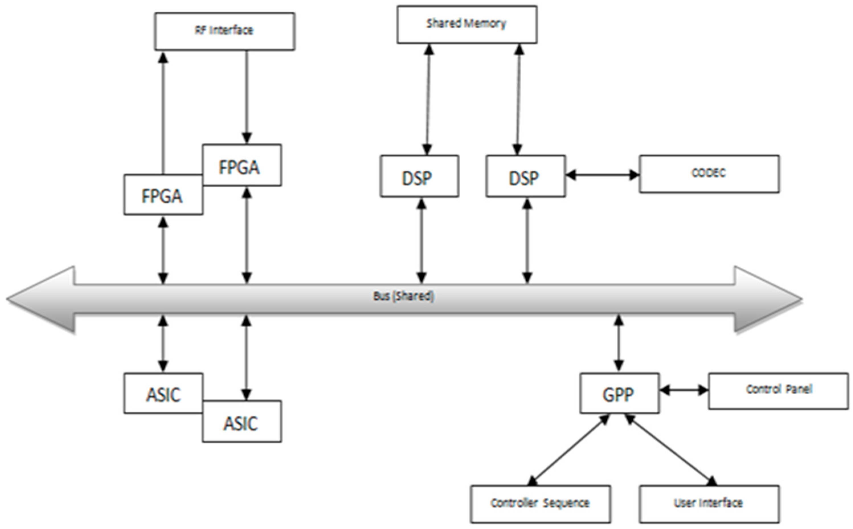
In this case, the SDR-embedded system allowed radio communications and offered reliable connectivity in all forms of severe environmental circumstances. Usually they are intended for the transfer multiple data streams, such as voice, images, video, or any other kind of data between the transceivers. The system under test is a high data rate communication system consisting of heterogeneous components, i.e., micro controller or general purpose processors (GPP), application-specific integrated circuits (ASICs), FPGA, and DSP. Many of these elements either are reconfigurable or programmable during the run time. A digital communication application specifically, and signal processing applications in common require sequential data stream processing, where input from one component is processed and transmitted to another component for more processing. The system also carries CODEC with related analog interfaces for voice-based applications. ASICs are used for analog-to-digital conversion, digital-to-analog conversion, digital up-conversion, and digital down-conversion.
On the other hand, the DSP is a microprocessor, of which the architecture was built specifically to support number-crunching for signal processing applications. A microcontroller is used to configure various components in the system and to interface with the control panel. The FPGAs provide the system’s glue logic, as well as interfaces with the system’s devices. A single shared bus is used by all PEs to communicate with each other and all the combined PEs are referred to as a SoC. In this model, all the components that need to interact with each other directly were connected using dedicated interconnects and they communicated via inter-processor communication. A digital signal processing embedded communication system that interfaces a digital design with the RF end is shown in Figure 18.
In this study, when inter-processor communication takes place in the system, sometimes data or packets may be lost, i.e., “breaking-up” of voice communication, data delay, data overriding, out of synchronization, etc. When we encounter these types of problems in a communication system, conversations alter drastically. The intended pauses in the conversation become longer when transmitted and may be mistaken for end of communication. This can happen when communication transceivers are on the move at high speeds or are in a difficult terrain where the loss of data occurs due interference from the environment. In such situations, data retransmission is required, which decreases the throughput of the system. This system has very high-speed synchronous interfaces that suffer from synchronization issues.
We have experienced several synchronization bugs between the different serial interfaces mentioned in Table 1. These bugs are not algorithmic or logic errors. They are mostly due to timing and synchronization. This kind of system testing differs from non-real-time system testing, and is also a difficult task.
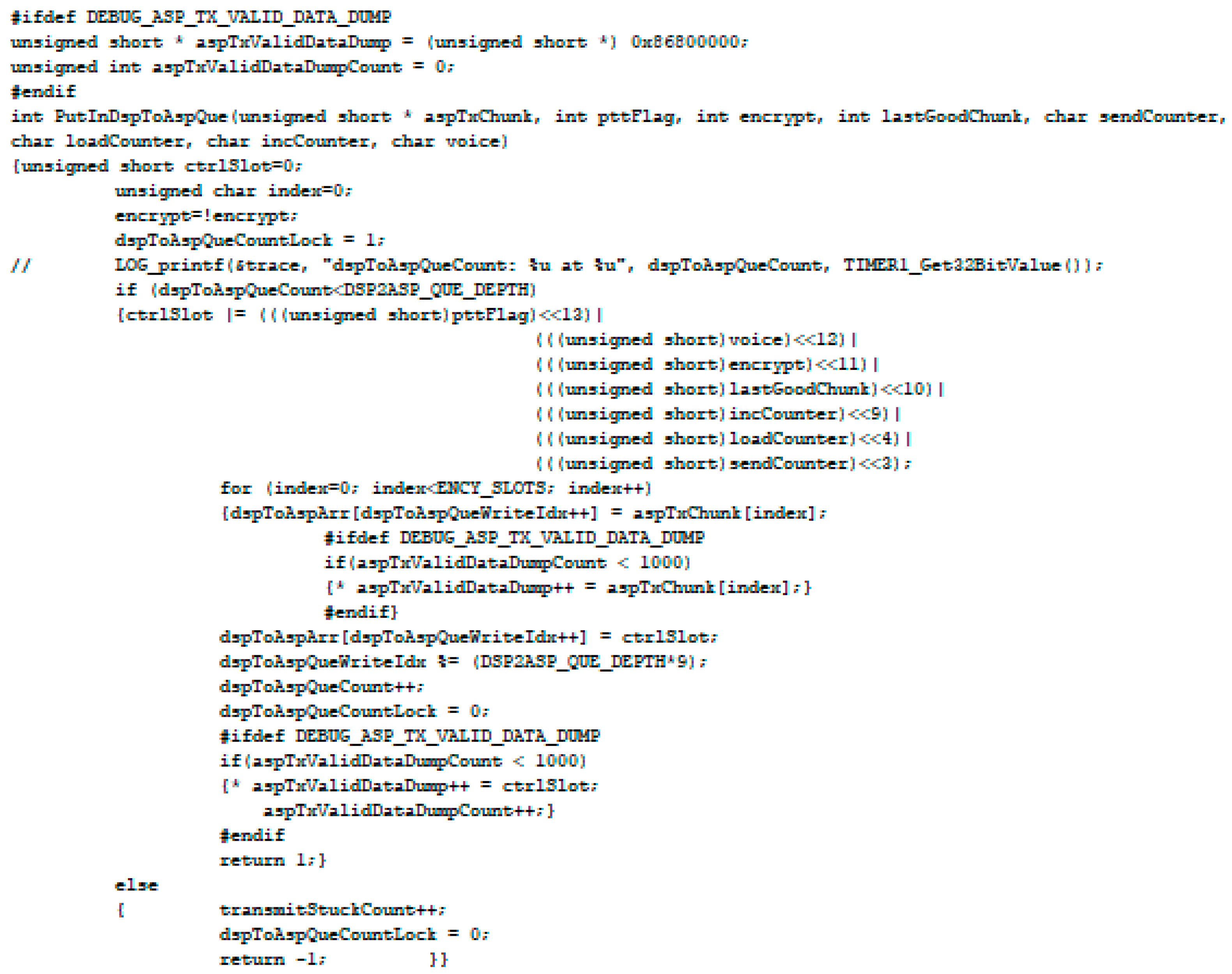
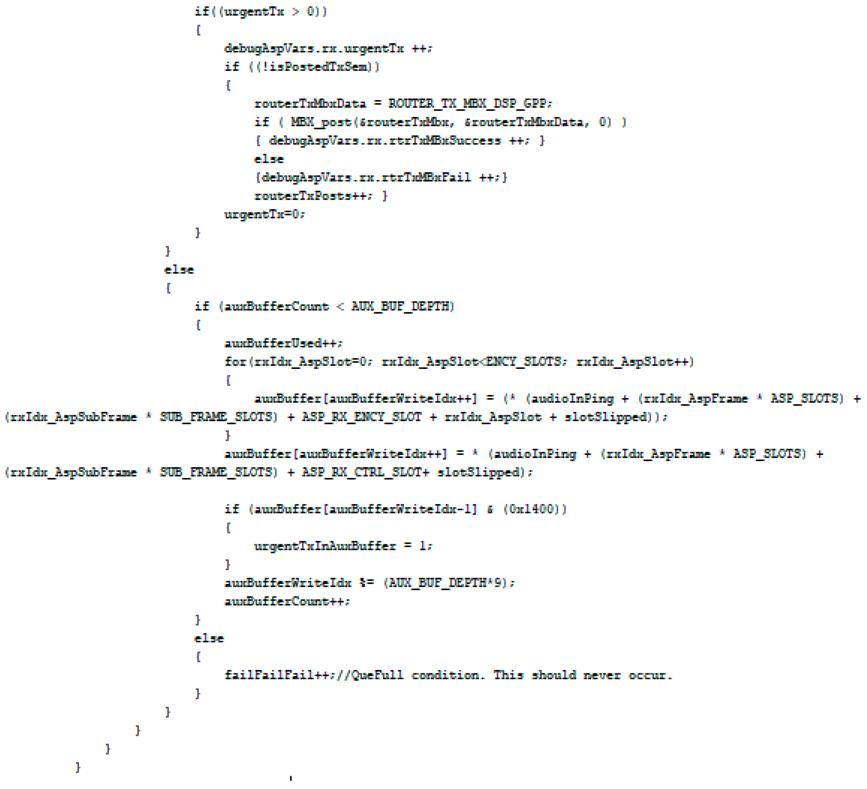
PutInDspToAspQue() function is used whenever data is transmitted through a serial port, shown in Figure 19, and the routerTxMbx mailbox is posted whenever data are received via a serial port in the SDR embedded system, shown in Figure 20.
The proposed framework has been assessed in this study and determined the synchronizations bugs in each interface, as well as the combination of these interfaces. These bugs could not force into the SDR embedded system, so we induced these bugs in MATLAB and created a knowledge base. The ramp signal was used because it is the best test signal to test these interfaces. All possible synchronization bugs mentioned in Table 1 were simulated in MATLAB. Several bugs were induced to see how the shape of the ramp signal changes. Therefore, we created all possible waveforms of the ramp signal. The knowledge base was created by inducing bugs on a single interface and in a combination of interfaces.
Once the knowledge base was created, the next step was the emulators. On the emulator side, different PEs simultaneously ran with interfaces. Every emulator of the PEs was connected to different PCs. Therefore, several screens of the PE interfaces showed what happens inside the PEs using emulators. The ramp signal was sent to all processors as it is visually the easiest signal to identify for bugs.
In this way, bugs were detected in the interfaces and then compared with a knowledge base. Once the system was in the development phase, we could not see through an emulator. In this case, the input was sent the final output of the system could be seen. Moreover, if the output was incorrect, the only way to go back and fix the bug was by using the proposed approach. Whenever a bug occurs during the inter-processor communication, we could refer to our knowledge base to identify the possible interface/interfaces causing the errors. The proposed framework should effectively simulate communication across multiple PEs for detecting and localizing bugs in real-time communication.
6. Discussion
Testing of real-time embedded systems is a demanding task due to bugs related to synchronization and the demand of high data rate transmission. Due to the continually rising data rate and the design complexity of embedded systems, researchers and testers are constantly striving to find new techniques to debug and test these interfaces. All previous work advocated testing high speed serial interfaces using electronic equipment and providing specification- and defect-based testing. This research focuses on a testing approach that detects and localizes all timing and synchronization bugs at high speed synchronous serial interfaces. Our approach is to simulate communication across multiple PEs for detecting and localizing bugs in real-time communication. For this purpose, we conducted a study based on inter-process communication and were able to identify communication-based synchronization bugs. While the source of bugs may be unknown or unidentifiable, it is important to locate bugs so that appropriate test cases may be generated.
The proposed framework helps to detect possible inconsistencies or communication bugs in communication protocol specifications while also providing failure traces as counter-test cases to assist in recreating a failure scenario. We generated test data that accommodate all kinds of scenarios on all PEs interfaces; we simulated communication based on these scenarios using test data in the knowledge base. Test cases were generated through use case scenarios. The proposed technique detects synchronization bugs systematically but more scenarios are still needed for testing. The framework also provides inputs for test case generation, which ensures that only a consistent communication model will be applicable.
Simulations have been used as quantitative process analysis tools in many domains and provide useful inputs for test case generation modules for detecting inconsistency in a system. It simulates the environment to examine a system’s consistency more closely, is created to allow testing of a virtual environment, and helps to determine different disturbances of a system. It also provides a thorough analysis of the functioning of the system. An instance of simulators created for knowledge base development is in the proposed framework.
Emulators are used after creating the knowledge base. On the emulator side, many PEs with distinct interfaces were executed simultaneously. Each of the PE emulators was linked to a separate PC. Using emulators, we could see what was happening in the system. In this manner, bugs were detected and then compared to a knowledge base.
A bug was injected into the system for validating the effectiveness of the proposed framework. Our approach was able to identify and localize the timing and synchronization bugs in high-speed synchronous serial interfaces in a real-time embedded system. As with other similar situations, the limitation of the work is in the need for more test cases that may be generated through other communication environments with real-time constraints. However, each new simulation environment will need to be able to enrich existing test cases that are continuously updated for further system testing.
7. Conclusions
An embedded system executes a variety of complex tasks in varied constraint environments. The typical issues are synchronization and inter-processor communication. These issues significantly affect the performance and complexity of real-time embedded systems. An embedded system contains multiple PEs that require synchronization to communicate with others across various types of high-speed interfaces. This paper presents a novel framework for testing real-time embedded systems containing high-speed serial interfaces that employ numerous simulator instances and emulators for capturing real-time data. The proposed framework develops a knowledge base through simulators for defining all timing and synchronization related bugs capable of thoroughly testing the high-speed synchronous serial interfaces of the embedded system. Results presented demonstrate effective embedded system testing using a multi-instance simulator. We verify this framework with a case study consisting of an embedded software-defined radio (SDR) system. The findings demonstrate the applicability of our framework for detecting and fixing bugs that otherwise would have been very hard to detect.
Author Contributions
Conceptualization, S.M., S.A.K. and A.H.; methodology, S.M., S.A.K. and A.H.; software, S.M.; validation, S.M. and S.A.K.; resources, A.H. and U.F.; data curation, S.M. and S.A.K.; writing—original draft preparation, S.M.; visualization, S.M.; supervision, S.A.K.; Review and Proofreading A.H. and U.F. All authors have read and agreed to the published version of the manuscript.
Funding
This research received no external funding.
Institutional Review Board Statement
Not applicable.
Informed Consent Statement
Not applicable.
Acknowledgments
All authors thank the Centre for Advanced Research in Engineering (CARE), Islamabad, Pakistan for providing a platform for validation of the proposed framework.
Conflicts of Interest
The authors declare no conflict of interest.
Appendix A
Appendix A.1.
Appendix A.2.

Table A1.
Test cases for Rx.
| Test Case ID | Test Scenario | Test Case | Pre-Condition(s) | Test Steps | Test Data | Expected Test Result | Post-Condition(s) | Actual Test Result | Status (Pass/Fail) |
|---|---|---|---|---|---|---|---|---|---|
| TC_RX-002-1 | Verify receiving data | Tx send the data and Rx receives the data | 1. Tx should be in place. 2. Rx should be in place. 3. There must be a test vector available. | 1. It begins when Tx sends the data. 2. If data received at the Rx end without any disruption then plot the Ram Else Wait for definite amount of time (Counter updated after timeout) End if | Normal Communication on both Tx and Rx end <Tx transmit the data> <Rx receives the data> | Successful Communication | Rx receive the data | Successful Communication | Pass |
| TC_RX-002-2 | Verify Receiving data | Tx send the data but Rx does not receive them due to some reasons | 1. Tx should be in place. 2. Rx should be in place. 3. There must be a test vector available. | 1. It begins when Tx sends the data. 2. If data received at the Rx end without any disruption then plot the Ram Else Wait for definite amount of time (counter updated after timeout) End if | <Tx transmit the data> <Rx does not receive the data> | Unsuccessful Communication | No data receive at Rx | - | |
| TC_RX-002-3-1 | Verify receiving data | Tx send the data to the Rx, but with (In) delay | 1. Tx should be in place. 2. Rx should be in place. 3. There must be a test vector available. | 1. It begins when Tx sends the data. 2. If data received at the Rx end without any disruption then plot the Ram Else if Data received at the beginning but after some times, the delay comes in communication (when delay comes, wait for a definite amount of time) then plot the Ram Else Wait for definite amount of time (counter updated after timeout) End if | <Tx transmit the data> <Rx receives the data but with delay anywhere in the middle.> | Communication take place (time constraint) | Data receive at Rx but with In delay | - | |
| TC_RX-002-3-2 | Verify receiving data | Tx send the data to the Rx, but with (start and In) delay | 1. Tx should be in place. 2. Rx should be in place. 3. There must be a test vector available. | 1. It begins when Tx sends the data. 2. If data receive at the Rx end without any disruption then plot the Ram Else if Data received after some delay (wait for definite amount of time) then plot the Ram Else Wait for definite amount of time (counter updated after timeout) End if | <Tx transmit the data> <Rx receives the data but with delay both at the beginning and anywhere in the middle> | Communication take place (time constraint) | Data receive at Rx but with (start and In) delay | - | |
| TC_RX-002-4 | Verify receiving data | Tx send the data and Rx receives the data | 1. Tx should be in place. 2. Rx should be in place. 3. There must be a test vector available. | 1. It begins when Tx sends the data. 2. If data are received at the Rx end, plot the Ram. Else Wait for definite amount of time (counter updated after timeout) End if | Normal communication on both Tx and Rx end <Tx transmit the data> <Rx overrides some packet of data > | Communication take place (overriding) | Rx receive the data but with data over riding at Rx | - | |
| TC_RX-002-5 | Verify receiving data | Tx send the data and Rx receives the data | 1. Tx should be in place. 2. Rx should be in place. 3. There must be a test vector available. | 1. It begins when Tx sends the data. 2. If data receive at the Rx end without any disruption then plot the Ram Else Wait for definite amount of time (Counter updated after timeout) End if | Normal communication on both Tx and Rx end <Tx transmit the data> <Rx receives the data> | Communication take place (out of sequence) | Rx receives out of sequence data | - |
Table A2.
Test Cases for ‘Tx’.
| Test Case ID | Test Scenario | Test Case | Pre-Condition(s) | Test Steps | Test Data | Expected Test Result | Post-Condition(s) | Actual Test Result | Status (Pass/Fail) |
|---|---|---|---|---|---|---|---|---|---|
| TC_TX-001-2-1 | Transmitting data from the Tx | Tx send the data with delay (In) to the Rx | 1. Tx should be in place. 2. Rx should be in place. 3. There must be a test vector available. | 1. It begins when Tx sends the data. 2. If data received at the Rx end without any disruption then plot the Ram Else if Data received at the beginning but after some times, the delay comes in communication (when delay comes, wait for a definite amount of time) then plot the Ram Else Wait for definite amount of time (counter updated after timeout) End if | <Tx transmit the data with delay (anywhere between transmission)> <Rx receives the data but with delay (anywhere between the transmission)> | Communication take place (time constraint) | Rx receive the data but with In delay | - | |
| TC_TX-001-2-2 | Transmitting data from the Tx | Tx send the data with delay (start and In) to the Rx | 1. Tx should be in place. 2. Rx should be in place. 3. There must be a test vector available. | 1. It begins when Tx sends the data. 2. If data received at the Rx end without any disruption then plot the Ram Else if Data received after some delay (wait for definite amount of time) then plot the Ram Else Wait for definite amount of time (counter updated after timeout) End if | <Tx transmit the data with delay both at the beginning and in the middle> <Rx receives the data but with delay both at the beginning and anywhere in the middle> | Communication take place (time constraint) | Rx receive the data but with delay (start and In) | - |
References
- Lande, M.R.S.; Ali, D.M.S. Synchronization in Embedded Real-Time Operating Systems. Int. J. Adv. Eng. Res. Dev. 2014, 1. [Google Scholar] [CrossRef]
- Akesson, B.; Nasri, M.; Nelissen, G.; Altmeyer, S.; Davis, R.I. An Empirical Survey-based Study into Industry Practice in Real-time Systems. In Proceedings of the Proceedings-Real-Time Systems Symposium, Houston, TX, USA, 1–4 December 2020. [Google Scholar]
- Walters, S.A. Practical objected-oriented approach for distributed real-time simulation. In Proceedings of the IEEE/AIAA 12th Digital Avionics Systems Conference, Piscataway, NJ, USA, 25–28 October 1993. [Google Scholar]
- Nelson, A.; Goossens, K.; Akesson, B. Dataflow formalisation of real-time streaming applications on a Composable and Predictable Multi-Processor SOC. J. Syst. Archit. 2015, 61, 435–448. [Google Scholar] [CrossRef]
- Tsao, S.L.; Lee, S.Y. Performance evaluation of inter-processor communication for an embedded heterogeneous multi-core processor. J. Inf. Sci. Eng. 2012. [Google Scholar] [CrossRef]
- Gill, S. The diagnosis of mistakes in programmes on the EDSAC. Proc. R. Soc. London. Ser. A. Math. Phys. Sci. 1951. [Google Scholar] [CrossRef]
- Engblom, J.; Girard, G.; Werner, B. Testing Embedded Software using Simulated Hardware. In Proceedings of the 3rd European Congress on Embedded Real Time Software, Toulouse, France, 25–27 January 2006. [Google Scholar]
- Gabauer, J. Test and Validation of the Integrity and Performance of High Speed Interfaces; Course: ENGG7290; The University of Queensland: St Lucia, Australia, 27 June 2019. [Google Scholar]
- Gude, L. High speed digital interface for radar applications. In Proceedings of the International Automatic Testing Conference AUTOTESTCON, Dayton, OH, USA, 21–24 September 1992; pp. 203–205. [Google Scholar] [CrossRef]
- Shen, Y.T.; Freibert, A.; Stergiopoulos, S.; Plataniotis, K. Computing architecture for the portable four-dimensional ultrasound diagnostic imaging system. In Proceedings of the IEEE International Ultrasonics Symposium, IUS, Dresden, Germany, 7–10 October 2012. [Google Scholar] [CrossRef]
- Tan, K.; Liu, H.; Zhang, J.; Zhang, Y.; Fang, J.; Voelker, G.M. Sora: High-performance software radio using general-purpose multi-core processors. Commun. ACM 2011. [Google Scholar] [CrossRef]
- Bandiziol, A.; Grollitsch, W.; Brandonisio, F.; Nonis, R.; Palestri, P. Design of a transmitter for high-speed serial interfaces in automotive micro-controller. In Proceedings of the 2016 39th International Convention on Information and Communication Technology, Electronics and Microelectronics, MIPRO 2016-Proceedings, Opatija, Croatia, 30 May–3 June 2016. [Google Scholar]
- Ruiz-Rosero, J.; Ramirez-Gonzalez, G.; Khanna, R. Field programmable gate array applications-A scientometric review. Computation 2019, 7, 63. [Google Scholar] [CrossRef] [Green Version]
- Patra, P. On the cusp of a validation wall. IEEE Des. Test Comput. 2007. [Google Scholar] [CrossRef]
- Hyunjin, K.; Abraham, J.A. On-chip source synchronous interface timing test scheme with calibration. In Proceedings of the 2012 Design, Automation & Test in Europe Conference & Exhibition (DATE), Dresden, Germany, 12–16 March 2012; pp. 1146–1149. [Google Scholar]
- Meixner, A.; Kakizawa, A.; Provost, B.; Bedwani, S. External loopback testing experiences with high speed serial interfaces. In Proceedings of the Proceedings-International Test Conference, Austin, TX, USA, 28–30 October 2008. [Google Scholar]
- Yesobu, M. Testing and Debugging of High Speed Serial Interfaces. Int. J. Elec. Comm. Comp. Eng. 2012, 3, 438–441. [Google Scholar]
- Arora, S.; Aflaki, A.; Biswas, S.; Shimanouchi, M. SERDES external loopback test using production parametric-Test hardware. In Proceedings of the International Test Conference, Fort Worth, TX, USA, 15–17 November 2016. [Google Scholar]
- Ichiyama, K.; Kusaka, T.; Ishida, M. A jitter injection module for production test of 52-Gbps PAM4 signal interfaces. In Proceedings of the International Test Conference, Washington, DC, USA, 9–15 November 2019. [Google Scholar]
- Ahn, S.U.; Seo, B.K.; Kim, H.W.; Shin, Y.S.; Kim, H.T.; Oh, G.G.; Kim, Y.D. Cost-Effective Test Method for screening out Unexpected Failure in High Speed Serial Interface IPs. In Proceedings of the International Test Conference, Washington, DC, USA, 26–28 October 2020. [Google Scholar]
- Perrella, S. Development of FPGA-Based, High-Speed Serial Links for High Energy Physics Experiments. EWSHM-7th Eur. Work. Struct. Health Monit. 2014, 3, 443–450. [Google Scholar]
- Mishra, S.; Singh, N.K.; Rousseau, V. System on Chip Interfaces for Low Power Design, 1st ed.; Imprint; Morgan Kaufmann: Waltham, MA, USA, 2015. [Google Scholar]
- Lomaro, S. Testing High-Speed Serial Interface Technology: Is Your Test Solution in Synch? In Proceedings of the Proceedings of the IEEE/CPMT International Electronics Manufacturing Technology (IEMT) Symposium, San Jose, CA, USA, 16–18 July 2003. [Google Scholar] [CrossRef]
- Hong, D.; Cheng, K.T. Efficient Test Methodologies for High-Speed Serial Links; Series: Lecture Notes in Electrical Engineering; Imprint; Springer: Dordrecht, The Netherland; London, UK, 2010; Volume 51. [Google Scholar] [CrossRef]
- Fan, Y.; Zilic, Z. Accelerating Test, Validation and Debug of High Speed Serial Interfaces; Springer Science & Business Media: Berlin/Heidelberg, Germany, 2011; ISBN 9789048193974. [Google Scholar]
- Hoefflinger, B. ITRS: The International Technology Roadmap for Semiconductors. In Chips 2020; Springer: Berlin/Heidelberg, Germany, 2011; pp. 161–174. [Google Scholar]
- Cases, M.; De Araujo, D.N.; Matoglu, E. Electrical design and specification challenges for high speed serial links. In Proceedings of the Proceedings of 7th Electronics Packaging Technology Conference, EPTC 2005, Singapore, 7–9 December 2005. [Google Scholar]
- Global Printed Circuit Board (PCB) Market 2012–2017 and 2018–2023-Growing Demand for High Speed Data and Signal Transmission, and Development of Green PCBs; PR Newswire: Dublin, Ireland, 2018.
- Kandalaft, N.; Attaran, A.; Rashizadeh, R. High speed test interface module using MEMS technology. Microelectron. Reliab. 2015. [Google Scholar] [CrossRef] [Green Version]
- Pcie, University of New Hampshire Inter Operability Laboratory, 2019. Available online: https://www.iol.unh.edu/sites/default/files/brochures/PCIe-Brochure.pdf (accessed on 4 March 2019).
- Test and Certification, Allion, 2019. Available online: https://www.allion.com/logo-certification/ (accessed on 4 March 2019).
- Moreira, J.; Werkmann, H. An Engineer’s Guide to Automated Testing of High-Speed Interfaces, 2nd ed.; Artech House, Inc: Canton St. Norwood, MA, USA, 2016; p. 685. ISBN 9781608079865. [Google Scholar]
- Fan, Y.; Zilic, Z. A versatile scheme for the validation, testing and debugging of high speed serial interfaces. In Proceedings of the IEEE International High-Level Design Validation and Test Workshop, HLDVT, San Francisco, CA, USA, 4–6 November 2009. [Google Scholar]
- Abdennadher, S.; Meixner, A. Why defect based testing works for high-speed I/O interfaces. In Proceedings of the DTS 2020-IEEE International Conference on Design and Test of Integrated Micro and Nano-Systems, Hammamet, Tunisia, 7–10 June 2020. [Google Scholar] [CrossRef]
- Abdennadher, S.; Shaikh, S.A. Practices in High-Speed IO testing. In Proceedings of the European Test Workshop, Amsterdam, Netherlands, 24–27 May 2016. [Google Scholar]
- Fan, Y.; Zilic, Z. BER testing of communication interfaces. IEEE Trans. Instrum. Meas. 2008. [Google Scholar] [CrossRef] [Green Version]
- Arora, H.; Jaliminche, L.N. Design and implementation of test harness for device drivers in SOC on mobile platforms. In Proceedings of the 2015 International Conference on VLSI Systems, Architecture, Technology and Applications (VLSI-SATA), Bengaluru, India, 8–10 January 2015. [Google Scholar] [CrossRef]
- Lee, S.S. External loopback testing on high speed serial interface. In Proceedings of the Proceedings of the 5th Asia Symposium on Quality Electronic Design, ASQED 2013, Penang, Malaysia, 26–28 August 2013. [Google Scholar]
- Ergenc, D.; Onur, E. Poster Abstract: ISDR: SDR-in-the-loop Simulation. In Proceedings of the INFOCOM 2019-IEEE Conference on Computer Communications Workshops, INFOCOM WKSHPS 2019, Paris, France, 29 April–2 May 2019. [Google Scholar] [CrossRef]
- Masood, S.; Khan, S.A.; Hassan, A. Simulating Synchronization Issues on a Multiprocessor Embedded System for Testing. In Proceedings of the 2021 IEEE International Conference on Information Communication and Software Engineering, Chengdu, China, 19–21 March 2021. [Google Scholar]
- Mark Strembeck, U.Z. Scenario-based Component Testing Using Embedded Metadata. In Proceedings of the Testing of Component-Based Systems and Software Quality, Erfurt, Germany, 30 September 2004. [Google Scholar]
- Cockburn, A. Structuring use cases with goals. J. Object Oriented Program. 1997, 10, 356–362. [Google Scholar]
- Fleisch, W. Applying use cases for the requirements validation of component-based real-time software. In Proceedings of the 2nd IEEE International Symposium on Object-Oriented Real-Time Distributed Computing (ISORC’99), Saint-Malo, France, 2–5 May 1999. [Google Scholar] [CrossRef]
- Fleisch, W. Simulation and validation of component-based automotive control software. In Proceedings of the 12th European Simulation Symposium (ESS 2000), Hamburg, Germany, 28–30 September 2000. [Google Scholar]
Figure 1.
Framework uses multiple instances of simulators with physical interfaces to emulate real-time embedded system.
Figure 1.
Framework uses multiple instances of simulators with physical interfaces to emulate real-time embedded system.

Figure 2.
Steps of the proposed framework.

Figure 3.
Simulator architecture.

Figure 4.
Multiple instances of simulator across PEs.

Figure 5.
Use case model.

Figure 6.
Test case mode.

Figure 7.
Fundamental activities for a test.

Figure 8.
Emulator environment.

Figure 9.
Emulators with multi interfaces.

Figure 10.
Normal communication (Tx to Rx).

Figure 11.
Delay at both ends (Tx and Rx). (a) Delay Tx (at the beginning), delay Rx (at the beginning) (b) delay Tx (in between), delay Rx (in between), (c) delay Tx (both ((a),(b) cases)), delay Rx (both ((a),(b) cases)).
Figure 11.
Delay at both ends (Tx and Rx). (a) Delay Tx (at the beginning), delay Rx (at the beginning) (b) delay Tx (in between), delay Rx (in between), (c) delay Tx (both ((a),(b) cases)), delay Rx (both ((a),(b) cases)).

Figure 12.
No data received at Rx.

Figure 13.
No data transmitted from Tx.

Figure 14.
Data overriding.

Figure 15.
No synchronization.

Figure 16.
Simulations in code composer studio. (a) Normal communication (Tx to Rx), (b) delay Tx (at the beginning), delay Rx (at the beginning), (c) delay Tx (in between), delay Rx (in between), (d) delay Tx (both ((b),(c) cases)), delay Rx (both ((b),(c) cases)). (e) No data received at Rx. (f) No data transmitted from Tx. (g) Data overriding. (h) No synchronization.

Figure 17.
Injected synchronization bugs.

Figure 18.
Digital signal processing embedded communication system interfaces.

Figure 19.
Code used whenever data are transmitted through serial port.

Figure 20.
Code used whenever data are received via serial port.

Table 1.
Synchronization bugs in inter-processor communication.
| Sr. | Identified Synchronization Bugs |
|---|---|
| 1 | Data received at Rx (receiver) with delay. |
| 2 | Data transmission from Tx (transmitter) with delay. |
| 3 | No data transmitted from Tx. |
| 4 | No data received at Rx. |
| 5 | Data overriding during communication |
| 6 | No synchronization |
Table 2.
Use case “data received at Rx with delay (start)”.
| ID | Usecase2-3_ IPC _Data Received at Rx with Start Delay |
|---|---|
| Name | Verify receiving data |
| Rationale | The Rx receives the same data as the Tx sends. |
| Actor | System |
| Goal | Check whether or not the data received at the Rx end. |
| Pre-condition(s) | - Tx should be in place—Rx should be in place—There must be a test vector available. |
| Flow of Event | 1. It begins when Tx sends the data. 2. If data receive at the Rx end without any disruption then plot the Ram Else if Data received after some delay (wait for definite amount of time) then plot the Ram Else Wait for definite amount of time (Counter updated after timeout) End if |
| Post-condition(s) | - Rx receives the data but with a delay at the beginning. |
| User Interface | - Two simulators instances |
| Notes | - |
| Data Implications | - Test vectors (Transfer of data from the Tx to the Rx interface (PE 1 to PE2)) |
| Scenario | Data received at Rx with delay. |
Table 3.
Test case for “Rx”- data received at Rx with start delay.
| Test Case ID | TC_RX-002-3 |
| Test Scenario | Verify receiving data |
| Test Case | Tx send the data to Rx, but with start delay |
| Pre-Condition(s) | 1. Tx should be in place. 2. Rx should be in place. 3. There must be a test vector available |
| Test Steps | 1. It begins when Tx sends the data. 2. If data receive at the Rx end without any disruption then plot the Ram Else if Data receive after some delay (wait for definite amount of time) then plot the Ram Else Wait for definite amount of time (counter updated after timeout) End if |
| Test Data | <Tx transmit the data> <Rx receives the data but with delay at the beginning> |
| Expected Test Result | Communication take place (time constraint) |
| Post-condition(s) | Data receive at Rx but with start delay |
| Actual Test Result | - |
| Status(Pass/Fail) | - |
Table 4.
Test cases for “Tx”.
| Test Case ID | Test Scenario | Test Case | Pre-Condition(s) | Test Steps | Test Data | Expected Test Result | Post-Condition(s) | Actual Test Result | Status (Pass/Fail) |
|---|---|---|---|---|---|---|---|---|---|
| TC_TX-001-1 | Transmitting data from the Tx | Tx does not send the data to Rx due to some reasons | 1. Tx should be in place. 2. Rx should be in place. 3. There must be a test vector available. | 1. Tx does not transmit the data. 2. If data are not received at the Rx end then Wait for definite amount of time (counter updated after timeout) End if | <Tx does not transmit the data> <Rx does not receives the data> | Unsuccessful Communication | No data receive at Rx | - | - |
| TC_TX-001-2 | Transmitting data from the Tx | Tx send the data with delay (start) to the Rx | 1. Tx should be in place. 2. Rx should be in place. 3. There must be a test vector available. | 1. It begins when Tx sends the data. 2. If data receive at the Rx end without any disruption then plot the Ram Else if Data are not received at the beginning but after some times, data receive (when delay comes, wait for a definite amount of time) then plot the Ram Else Wait for definite amount of time (ounter updated after timeout) End if | <Tx transmit the data with delay (at the beginning)> <Rx receives the data but with delay (at the beginning)> | Communication take place (time constraint) | Rx receive the data but with delay | - | - |
Publisher’s Note: MDPI stays neutral with regard to jurisdictional claims in published maps and institutional affiliations. |
© 2021 by the authors. Licensee MDPI, Basel, Switzerland. This article is an open access article distributed under the terms and conditions of the Creative Commons Attribution (CC BY) license (https://creativecommons.org/licenses/by/4.0/).
Share and Cite
MDPI and ACS Style
Masood, S.; Khan, S.A.; Hassan, A.; Fatima, U. A Novel Framework for Testing High-Speed Serial Interfaces in Multiprocessor Based Real-Time Embedded System. Appl. Sci. 2021, 11, 7465. https://doi.org/10.3390/app11167465
AMA Style
Masood S, Khan SA, Hassan A, Fatima U. A Novel Framework for Testing High-Speed Serial Interfaces in Multiprocessor Based Real-Time Embedded System. Applied Sciences. 2021; 11(16):7465. https://doi.org/10.3390/app11167465
Chicago/Turabian StyleMasood, Sabeen, Shoab Ahmed Khan, Ali Hassan, and Urooj Fatima. 2021. "A Novel Framework for Testing High-Speed Serial Interfaces in Multiprocessor Based Real-Time Embedded System" Applied Sciences 11, no. 16: 7465. https://doi.org/10.3390/app11167465
Note that from the first issue of 2016, this journal uses article numbers instead of page numbers. See further details here.