
Review of Magnetorheological Damping Systems on a Seismic Building
by
 , , ,
, , ,
Bhre Wangsa Lenggana
1, 
Ubaidillah Ubaidillah
1,*,
Fitrian Imaduddin
1,
Seung-Bok Choi
2,3,*,
Yusep Muslih Purwana
4 and
Harjana Harjana
5 1
Department of Mechanical Engineering, Faculty of Engineering, Universitas Sebelas Maret, Surakarta 57126, Indonesia
2
Department of Mechanical Engineering, The State University of New York, Korea (SUNY Korea), Incheon 21985, Korea
3
Department of Mechanical Engineering, Industrial University of Ho Chi Minh City, 12 Nguyen Van Bao Street, Vap District, Ho Chi Minh City 700000, Vietnam
4
Department of Civil Engineering, Faculty of Engineering, Universitas Sebelas Maret, Surakarta 57126, Indonesia
5
Department of Physics, Faculty of Mathematics and Physics Sciences, Universitas Sebelas Maret, Surakarta 57126, Indonesia
*
Authors to whom correspondence should be addressed.
Appl. Sci. 2021, 11(19), 9339; https://doi.org/10.3390/app11199339
Submission received: 9 August 2021
/
Revised: 26 September 2021
/
Accepted: 30 September 2021
/
Published: 8 October 2021
(This article belongs to the Special Issue Magneto-Rheological Fluids)
Abstract
:Featured Application
The discussion in this article could be used as a literature study on the application of semi-active damping to building structures in general and the application of MR dampers to building structures specifically related to earthquake damage mitigation.
Abstract
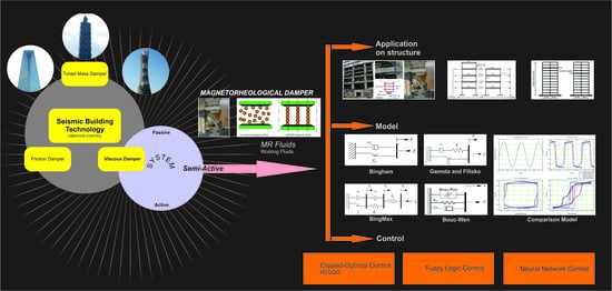
Building structures are vulnerable to the shocks caused by earthquakes. Buildings that have been destroyed by an earthquake are very detrimental in terms of material loss and mental trauma. However, technological developments now enable us to anticipate shocks from earthquakes and minimize losses. One of the technologies that has been used, and is currently being further developed, is a damping device that is fitted to the building structure. There are various types of damping devices, each with different characteristics and systems. Multiple studies on damping devices have resulted in the development of various types, such as friction dampers (FDs), tuned mass dampers (TMDs), and viscous dampers (VDs). However, studies on attenuation devices are mostly based on the type of system and can be divided into three categories, namely passive, active, and semi-active. As such, each type and system have their own advantages and disadvantages. This study investigated the efficacy of a magnetorheological (MR) damper, a viscous-type damping device with a semi-active system, in a simulation that applied the damper to the side of a building structure. Although MR dampers have been extensively used and developed as inter-story damping devices, very few studies have analyzed their models and controls even though both are equally important in controlled dampers for semi-active systems. Of the various types of models, the Bingham model is the most popular as indicated by the large number of publications available on the subject. Most models adapt the Bingham model because it is the most straightforward of all the models. Fuzzy controls are often used for MR dampers in both simulations and experiments. This review provides benefits for further investigation of building damping devices, especially semi-active damping devices that use magnetorheological fluids as working fluids. In particular, this paper provides fundamental material on modeling and control systems used in magnetorheological dampers for buildings. In fact, magnetorheological dampers are no less attractive than other damping devices, such as tuned mass dampers and other viscous dampers. Their reliability is related to the damping control, which could be turned into an interesting discussion for further investigation.
1. Introduction
Earthquakes are responsible for the loss of thousands of lives and billions of dollars in damages to properties. Therefore, designing a structural building capable of withstanding seismic forces has become a primary concern in the field of engineering [1]. The most common conventional design approaches largely depend on a structure’s ability to absorb an earthquake’s input energy by deforming inelastic sections that were exclusively designed into a structural system while preserving the structural stability and integrity. Engineers have attempted to design and develop technologies that prevent and mitigate seismic hazards, such as earthquakes [2].
The development of seismic engineering technology goes hand in hand with dis-cussions on earthquake disasters. Although humans cannot escape natural disasters, they can be mitigated to minimize damage [2,3]. To date, seismic engineering specialists have gained only a limited understanding of crustal behavior. As such, predicting the magnitude, time, and distance of an earthquake is exceptionally complicated and beyond the ability of scientific knowledge at times as earthquakes occur spontaneously [4,5,6].
Earthquakes are vibrations generated within the Earth by sudden movements when sheared rocks are stretched beyond their elasticity [7]. They are a unique phenomenon produced by tectonic activities within the Earth’s crust. Earthquakes that occur in a region can, to a certain extent, be felt in the surrounding areas [8]. The impact of an earthquake is random and is measured by its magnitude. Large-magnitude earthquakes result in property damage in the earthquake region. Although the ground motion amplitude of an earthquake is determined by its magnitude, distance plays a crucial role in the mitigation of seismic hazards. Therefore, the characteristics and potential impact of an earthquake must be understood during a seismic hazard analysis [9,10,11,12]. Earthquakes occur when tectonic plate movements accumulate energy. When released, this energy radiates in all directions in the form of earthquake waves [13,14]. Earthquakes commonly produce two types of seismic waves: (1) body waves and (2) surface waves. These seismic waves often occur only after an earthquake or an explosion [13,15,16,17].
A body wave spreads throughout the inside of the Earth and causes minimal damage to building structures. These waves can be divided into two types: (1) P waves (longitudinal waves); and (2) S waves (transversal waves). A P wave, or a longitudinal wave, has a very swift time propagation compared with other waves. The velocity of a P wave is between 1.5 km/s and 8 km/s in the Earth’s crust and can spread through solid, liquid, and gas media. An S wave, or a transversal wave, has a slower spread than a P wave. The velocity of an S wave is typically 60% to 70% slower than a P wave. The direction of particles in an S wave also differs from that in a P wave in that it is perpendicular to the direction of the propagation wave. A surface wave can be likened to water, as a surface wave spreads on the Earth’s surface [18,19,20,21,22,23]. It not only has a slower propagation time than a body wave but a lower frequency as well. As such, surface waves are more damaging to building structures than body waves [24,25]. The amplitude of a surface wave declines rapidly as the depth increases. This is due to the dispersion of the surface wave, with the wave factorization based on the wavelength of the propagation wave [26,27].
Potential damage can be estimated and understood using the peak ground velocity (PGV), which relates to intensity. Trinufac and Brady (1975) established an empirical correlation between PGV and the modified Mercalli intensity scale (MMI); however, their regressions focused on intensity only [28,29]. As such, a PGV estimate makes it possible to approximate the MMI. Other studies have also conducted observational regressions of PGV intensity to estimate the correlation between PGV and MMI [30,31,32,33,34,35,36,37,38]. Wald et al. investigated the correlation between PGV and intensity; however, they used peak ground acceleration (PGA) in association with PGV to derive a correlation to intensity. This correlation is used when making earthquake maps [39]. Kaka and Atkinson created a new correlation to map earthquakes in eastern North America. They found the equation used by Wald et al. to be incompatible with the application of their study. This occurred as a result of different ground motion properties, where the frequency is much higher in stable continental regions such as eastern North America. As such, they modified the equation to use PGV to estimate high and low intensities [34,39]. Gerstenberg et al. (2005) then used the equations created by Kaka and Atkinson as well as Wald et al. to investigate a similar case [40].
The current design methods employed for seismic activities allow structures to undergo plastic deformation during large earthquakes while remaining elastic during small and medium earthquakes. The design of a structural damper must generally fulfil requirements for both wind and earthquake actions [2,41,42,43,44]. However, the calculations behind designing for the effects of wind forces and earthquakes differ. For instance, structural designs for wind loads use force as a consistent basis as the pressure on the exposed surface area tends to hit a building directly. This is called force-type loading. In structural designs for earthquake loads, building structures are more likely to experience random movements and vibrations from the ground floor. This causes an inertial force within the building and results in stress. This is called displacement-type loading [45,46,47,48]. Another way of expressing this difference is through the load–deformation curve of the building; i.e., the demand on a building is the type of force imposed by the displacement-type wind pressure imposed by random earthquake shocks.
Another distinguishing feature between force-type loading and displacement-type loading is the load–deformation curve of a building. The demand on a building structure is the type of force imposed by the pressure displacement-type loading due to random shocks [44]. Shakes from an earthquake are time-variant and have very random waves and accelerations. On the other hand, most of the designs represent the inertial force due to the earthquake as a definite effect of random vibrations [2,49,50].
The ground motion that occurs during the earthquake process is cyclic to the neutral position of the structure. Therefore, in a seismic action, there are many complete references and the time duration of the earthquake tends to be small, thereby causing stress on the building [45,49]. Several studies on the statistical equations of seismicity have been carried out without separating the use of ground motion data sets in terms of distances to the nearest fault line [51,52,53,54,55]. The engineering field has extensively investigated and developed algorithms and control systems. In this case, they are algorithms and control systems for mitigating natural disasters, particularly earthquakes [54,55,56].
Over the last few decades, the field of structural engineering has extensively investigated the development of smart structure technologies for structural seismic response controls. This is because smart structures are considered to be effective at handling earthquakes. Rather than rebuilding a structure, some studies have used a large number of innovative devices and systems to protect buildings from earthquakes [56].
However, as earthquakes have several kinds of waves, they may still damage a building. Therefore, several technological devices, such as friction dampers (FDs), tuned mass dampers (TMDs), and viscous dampers (VDs), that purport to adapt to seismic activity are considered capable of adequately handling earthquakes. Recently, smart materials, such as shape memory alloys and magnetorheological (MR) fluids, have been combined with devices to absorb seismic energy. However, semi-active systems have received more attention because they offer impressive adaptability and a very low power requirement [57,58,59,60,61].
As most flexible structures, such as heavy and tall buildings and bridges, have minimal structural damping and are prone to dynamic excitation from wind or seismic vibrations, different control mechanisms are used to prevent structural failures. There are three types of control systems for building structures: passive, active, and semi-active or hybrid systems. Although passive control systems have been extensively studied [62], active and semi-active systems have also been investigated as a control for structures [63].
2. Types of Dampers on Structural Buildings
2.1. Friction Dampers
Friction dampers (FDs) generate the desired energy discharges via the friction produced by two solid bodies sliding relative to each other. This is a common process used in the engineering field. It can also be applied to seismic building structures. This friction can also be used, on a smaller scale, to absorb kinetic motion energy [63,64,65]. As such, Pall et al. (1980) developed passive FDs to improve a structure’s seismic responses. This was based on the resistance developed between two interfaces to remove a number of different input energies. During seismic stimulation, the device was found to provide the desired amount of energy dissipation under a predetermined load. It was also found to be immune to thermal effects and have reliable performance and stable hysterical behavior [66].
The device proposed by Pall et al. (1980) for the seismic control of large-paneled structures joined brake pads between steel plates to provide a consistent response to force shifting [66]. Some building structures in Canada have implemented a modern version of this device model [67]. Another similar study applied a copper alloy friction bearing to a Sumitomo friction damping device that slides along the inner surface of a cylindrical steel casing. The action of the spring on the resulting inner and outer sections provided the required normal force [68,69]. The device was able to reduce the displacement in comparison with the original configuration of the structure. The small modifications that were made in the new configuration at the base increased the shear forces and acceleration in some cases.
The reduction in seismic energy received by the device was due to the values of the forces acting on the FD. The load at which slip begins to occur and the damper begins to separate the seismic energy is called the FD slip load. This slip load determines the energy dissipation capacity of the FD. In this case, the FD had an optimal slip load. This corresponds to the lowest number of responses from the structure. A 10% to 15% variation in the mean slip load was sufficient to influence many structural responses. Multiple studies have arrived at the same conclusion [68].
As FDs have nonlinear behavior, nonlinear time history analysis is required to analyze the friction of damped structures. Large, rectangular, and almost sturdy FD hysteresis loops indicate a higher energy dissipation capacity. Therefore, a damped brace that generates the FD slip load can model the FD provided that it is in an elastic clamp.
Several studies have investigated the performance of FDs, with some focusing on FDs installed in reinforced concrete (RC) frame structures. The Structural Analysis Program2000® (SAP2000®) software was used in these cases to investigate samples from seismic zones in India. The skid load determination was adjusted to find the response of the frame without damping and the frame with a FD. The obtained results were then compared and the decrease in displacement and mean force were estimated [70,71].
The design of the slip load significantly affects the efficiency of the FD. The responses of a seismic structure can be described as the application of energy to the structure and the energy dissipation of the structure. As such, the difference between these two energies can be minimized through an optimal design [67,72,73]. However, the energy lost due to friction within the structure must also be maximized [74]. Several studies have investigated multiple optimal viscous and viscoelastic reducing designs [75,76,77]. However, only a handful of studies have investigated the optimization of FDs for seismic loads. Filiatrault and Cherry investigated the slip load spectrum of a design to maximize the energy dissipation while taking into account ground motion and structural properties. This study was performed to determine the optimal slip load distribution for FDs [72,78]. The authors also investigated the optimal slip load value for peak ground acceleration. To that end, it was assumed that the FD would not slip when subjected to strong wind loads. The FD was assumed to only slip when exposed to a strong earthquake load. Moreschi and Singh used genetic algorithms (GAs) to determine the optimal placement of friction absorbers on structures and metals in a reinforced steel frame. Fallah and Honarparast also investigated the use of GAs to optimize the slip load distribution and placement of Pall FDs. This was accomplished by developing a nondominant genetic sorting algorithm for multilevel shear wires. Patro and Sinha found that a shear frame structure with dry friction produced a uniform slip load distribution for the optimal seismic response with various ground motion characteristics to determine the appropriate slip load [72,79,80].
Some researchers have concluded that retrofitting existing buildings with a passive control system for seismic activities is the most convenient solution. One study suggested using a FD and a bracing system in a steel frame. This not only reduced the seismic demand but also increased the ductility to generally improve the seismic performance [81]. The advantages of this method are the development of a stable, rectangular hysteresis loop and independence under environmental conditions such as temperature and loading rate. In addition to FDs, masonry filler panels were found to increase the seismic resistance of steel structures by increasing their lateral strength and stiffness as well as reducing the drift in the storyline. Zahrai et al. investigated the effect of brick-filling panels on the seismic performance in a four-story, three-span steel frame with Pall® FDs. They found that FDs in the steel frame increased the ductility and decreased the drift to less than 1%. However, the infill panels not only fulfilled their function during the imposition of drift but also increased the structural strength. Therefore, the use of infill panels in conjunction with FDs was found to reduce the number of dynamic structural responses as the infill panels dissipated the input energy of the earthquake by 4% to 10% depending on the thickness [80].
Borislav and Mualla proposed a new type of FD device for a steel frame story with seismic loading. At the time, the novelty was that the proposed material provided a very stable performance over a long cycle, was resistant to adhesive wear, and did not damage the surface of the steel plate. Their experimental study assessed the friction-bearing material, the performance of the damping unit, and the response of the scaled model’s frame to harmonic excitation. This study was almost identical to the study by Zahrai et al., which added infill panels to a brick building. In any case, Borislav and Mualla found an increase in the dynamic response in comparison with conventional methods [80,82].
Various innovations have been used to improve the performance and demonstrate the efficacy of FDs in building structures. Software has also been used as an evaluation tool in several case studies. Baratia et al. studied the seismic behavior of a building that had been retrofitted with FDs. The seismic performance of steel structures that were either 6, 9, or 12 storys tall was evaluated with and without the use of dampers. A finite element modeling technique, namely SAP2000®, was used to analyze the performance of friction absorbers in these asymmetrical structures. The study found a significant increase in seismic behavior, which demonstrated the efficacy of FDs as tools for seismic reinforcement in these buildings [83]. Chandra et al. used the Extended Three-Dimensional Analysis of Building Systems® (ETABS®) software to dynamically analyze the nonlinear dimension time history of a new structural system of FD frames in an 18-story apartment building. The critical 5% viscous damping value was assumed to be in the initial elastic stage in order to account for the presence of nonstructural components [84].
In contrast, Shao et al. developed a cross-braced FD to seismically enhance a 36-foot tall concrete shear wall building with soft floors that had been built in the 1970s in the greater Seattle area. The first two floors of this building consisted of a relatively rigid concrete podium, while the subsequent two floors had concrete columns to support the sliding concrete walls of the upper floors. Therefore, the two floors above the podium were soft and considered to be earthquake-prone during seismic events (10%/50 years). The floor’s reinforcement involved long clamps and tension bars at the junction of each clamp, which was where the FDs were placed. Two 890 kN capacity cross-supporting FDs were installed within the 12 perimeters of the soft floor, bringing the total number of friction absorbers used to 24. Two silencer prototypes were designed, built, and tested by Pall Dynamics Inc. to ensure the performance. The installation of these dampers was completed in 2005. The dampers were found to increase the structural integrity, improve the building’s safety, and help minimize structural and nonstructural damage after an earthquake, thereby reducing the potential downtime and repair costs after a seismic event [85].
An effective mechanism that uses a similar principle in the case of seismic damping is the triangular-plate-added damping stiffness (TADAS) damper. The TADAS damper is an effective mechanism for reducing the energy input to structures during an earthquake via metal deformation that is not elastic. In general, the damper device consists of several triangular plates welded to the same base plate. Each triangular plate is inserted into the perforated base plate before welding. During an earthquake, interstellar drift causes movement of the upper end of the TADAS damper relative to the lower end. This causes the metal plate to be removed from the damper and, as a result, its energy is dissipated [86,87]. In addition, there are other damper models, such as shear panels or plates. Shear walls are innovative lateral force retaining systems that are able to effectively help buildings resist wind and earthquake forces [88,89,90,91,92]. Model shear panels or plates have properties that are fundamentally useful to resisting seismic forces and increasing the initial rigidity of a tall building structure. This model also has inherent redundancy and a substantial energy dissipation capacity, reducing the erection time and structure costs. Most importantly, compared with other shear walls, such as equivalent reinforced concrete, the low weight of the shear plates reduces, by about 30%, the gravity-related mass and seismic force (inertia) transmitted to the foundation [93,94,95,96,97]. Steel plate shear walls were in use from the 1970s to the mid-1980s. The failure mode of the plate shear wall is considered to be out-of-plane buckling of the inner plate. This resulted in experts building structures that are very rigid, which offers an economic advantage over concrete shear walls. In Japan, the trigger has been designed to be a rigid trigger or a thick plate to prevent local buckling [98,99,100,101,102]. Apart from the use of steel, pure aluminum is also used as a base isolation for the manufacture of innovative passive energy dissipation devices. Base isolation is the most effective method for designing seismic buildings. The pure aluminum is also intended to provide seismic protection in framed buildings. The use of this metal can be said to be a novelty in the field of civil engineering that is quite interesting [103].
2.2. Tuned Mass Dampers
Tuned mass dampers (TMDs) are a type of passive device often used to control the response of buildings and bridges. A TMD consists of a mass–spring system attached to the main structure of a building or bridge and is usually installed on the roof of the structure to counteract the ground’s motion to reduce the dynamic response of the structure.
The dissipation of energy is achieved by the inertial damper forces acting on the structure [104,105]. These systems are primarily efficient at controlling wind-generated vibrations in lean structures, such as towers and tall buildings. TMDs can be classified into three categories: tuned liquid dampers; TMDs; and tuned liquid column dampers.
A TMD is the classic configuration of a tuned damper and consists of a properly adjusted damping element and a secondary mass with a spring to increase the attenuation of a primary structure resulting from frequency-dependent hysteresis. Therefore, TMDs can be credited with increasing the damping of a structural system. Although these devices effectively reduce wind-excited responses to stationary narrowband stimuli, they are less effective for broadband excitations, such as earthquakes [105].
The scheme of a TMD is shown in Figure 1 [106]. It consists of a mass, spring stiffness in the structure, and damping for earthquake excitations. Numerous numerical, analytical, experimental, and optimal structural studies have been carried out to determine the efficacy of TMDs in reducing the seismic response of structures. Lin et al. developed and implemented TMDs in building structures [106]. The study used real earthquake data in its numerical and statistical analysis of torsion in an installation in a five-story building. The results show that passive TMDs effectively reduced the response of the building during an earthquake. A similar experimental study conducted by Zuo et al. developed a TMD with multiple degrees of freedom and optimized the two degree of freedom system [107].
During its development, the TMD was quite a popular device, and it has been ap-plied to several building structures. Several theoretical and experimental studies have been conducted on TMDs. Peter (2006) theoretically and experimentally analyzed TMDs. Marano et al. (2007) used linear TMDs to control seismic excitation in buildings with limited reliability based on technical optimizations. While both Marano et al. (2007) and Peter (2006) agree that TMDs optimize a building’s response to seismic loads [108,109], Pinkaew et al. found that TMDs were not effective at reducing vibrations [110].
Not all studies on TMDs have analyzed their performance. Other studies investigated TMDs in terms of cost optimizations [111,112,113,114,115]. Huang et al. compared the redistribution of structural materials and the application of TMDs to benchmarks for reinforced concrete structures with a 60-story steel belt frame with wind loading. The study concluded that a redesign of the building’s standards, to meet inter-story deviations and the peak acceleration, would require a 14% increase in initial material costs, while using adjustable mass dampers would only require a 3.6% increase in the initial structural material costs [112]. However, TMDs can only reduce the free vibrations of a tall building structure. This also only happens when the earthquake ends. This is because TMDs have the task of mitigating the structural acceleration caused by wind on tall buildings. Various types of TMDs, including both passive and active TMDs, have been applied in several buildings in multiple countries. The most recent application of a TMD is shown in Figure 2.
The development of the TMD also gave rise to the new idea of using liquid as a mass to balance the structure of a building when it vibrates. A tuned liquid damper (TLD) is a type of TMD. In this case, the mass used is replaced with a liquid (usually water). The effects of external vibrations are balanced through the movement of water in the tube or tank. This concept is not new, and it has been used to stabilize ship structures for many years [114]. In TLDs, the horizontal tube movement controls the fluid flow, which is adjusted to a certain frequency [115,116,117,118,119,120,121]. However, the application of a TMD to a building structure, especially in order to overcome earthquake loads, requires further examination before it can become a reality.
2.3. Viscous Dampers
One of the countermeasures for reducing seismic vibrations is to use an evaluation of the seismic design approach. In order to evaluate such a seismic design approach with nonlinear dynamic analysis, a robust model for the steel device and damper depending on the rating is required. Accurate models have been proposed for viscous, viscoelastic, and elastomeric fluids that are rate dependent [122,123]. Fully active control systems apply both dissipative and non-dissipative forces to a structure. A properly designed fully active control system is capable of significantly increasing the damping in comparison with a passive system. However, controlling these devices requires a large amount of power and suffers from instabilities due to time delays. Moreover, these active systems will probably malfunction in the event of an electrical failure or damage as the control system ceases to operate and the damping device cannot change the system to a passive system. In this case, an active system provides a wider range of technologies. However, the actuator controller relies on an external power source to apply force to the structure. Therefore, providing optimal responses in relation to demand can be accomplished by adding or removing the applied force [124].
In control engineering, an active system consists of four interconnected components: (1) the plant (i.e., the building); (2) the sensors; (3) the controller or control computer; and (4) the actuators. Each of these components functions as a subsystem and is integrated in a closed feedback control loop such that the output of one component is the input of another component [125]. Although full-scale active systems have been implemented in research structures, the lack of reliability and the lack of cost-effectiveness have limited their widespread use in non-research models, which prefer to adopt passive systems instead. Therefore, full-scale active systems are still under investigation by many users and researchers. However, many studies have developed damping devices that optimize the cost-effectiveness and the potential reliability to provide a solution for both passive and active systems. As such, researchers have shifted their focus to semi-active systems in recent times [126,127].
The development of damping devices that use semi-active systems progressed rapidly as they require significantly less energy to control than active systems. This is because semi-active systems do not require the addition of mechanical energy to the structural system. Therefore, the bounded input guarantees the stability of the bounded output. This type of device is also referred to as a controllable passive system [126,128]. Semi-active systems provide electrical safety as, if the electrical device malfunctions or fails, the system converts into a passive system. This differs greatly from an active system, which relies on a considerable amount of power to control the system and increase performance. Semi-active systems do not require tremendous amounts of power to increase performance as feedback from the external sensors in the internal control mechanism dictates its dissipative or resistive power. This enables the system to inversely combine elements from active to passive or vice versa [128].
Semi-active systems effectively minimize structural damage under large environmental loads and provide three main advantages over active and passive systems. As they are very dissipative, they do not add energy to the system, thereby guaranteeing stability. Unlike passive systems, semi-active systems are also able to change their structural behavior due to nonlinearity, degradation, or damage over time. A recent study on semi-active systems demonstrated their efficacy for seismic control using viscous fluid dampers. Magnetorheological (MR) dampers are relatively inexpensive semi-active devices that are not only reliable but also provide electrical failsafes.
3. Magnetorheological Dampers for Structural Buildings
3.1. Magnetorheological Fluids
When subjected to a magnetic field, magnetorheological fluids change their rheological behavior in response to growing yield stresses. As such, MR fluids have great potential in the development of electromechanical devices as they provide a simple, responsive, quiet, and quick interface between mechanical and electronic control systems [129,130,131].
MR fluids were first discovered by Jacob Rabinow and have only grown in popularity since then. MR fluid is considered to be a multifunctional intelligent fluid as it can be rapidly modified and reversed in a short period of time (milliseconds) when a magnetic field is applied. In the absence of a magnetic field, MR fluids behave like Newtonian fluids. The magnetic field applied to MR fluids changes the arrangement of particles to form a chain-like shape. This chain-like shape modifies the fluid’s rheological properties by drastically changing the value of the viscosity. This change in viscosity results in yield stress changes depending on the magnitude and direction of the applied magnetic field. The characterization of the rheological behavior of these fluids occurs at two stages: pre-yield and post-yield [132,133].
Due to the unique characteristics of MR fluids, the application of magnetic fields can dramatically change their rheological properties. MR fluids have been used to successfully develop various brake systems, dampers, and other devices. In most of these applications, the surface of the device is in contact with the MR fluid because it requires relative motion, such as linear motion in the case of shock absorbers, to operate. However, the surface of the device wears out more rapidly due to the abrasive nature of the iron particles in the MR fluid. As such, selecting the right surface material is essential to ensure high resistance to wear as well as durability [133,134].
The main components in a MR fluid formation are the carrier fluid, magnetic particles, and the additives. Carbonyl iron, with a purity of 99%, is often used to provide the magnetic particles due to its high magnetic permeability and magnetization saturation [135]. Moreover, the chemical deposition of pentacarbonyl iron vapor produces carbonyl iron particles, which usually form into spheres, thereby reducing wear and tear on the walls of devices that use MR fluids [136,137]. However, the findings of one study suggest that fiber particles provide better yield stresses with lower viscosities. In some applications, carbonyl iron particles range between 3 μm and 5 μm in size with particle concentrations between 20% and 40% depending on the volume. As such, the likelihood of wear from erosion and friction is nominal due to the particles’ minute size [138].
Oils with low viscosity, such as silicone oil, mineral oil, and other synthetic oils, are used as carrier fluids as they are excellent at forming MR fluids due to their wide range of viscosity-changing objectives. However, the carrier liquid must be non-reactive with the iron particles. Silicone oil is often used as a carrier fluid in vibration control applications due to its high viscosity index, low vibration, high shear strength, and high flash point [135].
The additives used are usually surfactants that prevent agglomeration and reduce the deposition rate of the magnetic particles [139]. This is essential as high-density particles tend to settle, which can render the device ineffective if left untreated [138]. Additives such as oils, thixotropic agents [140], and Span® 80 and TWEEN® 80 emulsifiers are often used to improve the sedimentation stability [141], while organic acid and stearic acid are often used to increase the density of the carrier liquid [135] and stabilize the sedimentation [138].
3.2. Application of MR Dampers in Building Structures
Due to their superior quality, MR dampers are in high demand for use in scientific case studies and in several real-world industrial applications. Carlson and Weiss concluded that MR dampers provide good operating reliability as temperature fluctuations and impurities in the fluid did not affect the performance and functionality. However, a significant drawback was their nonlinear characteristics, which involve hysteresis (force vs. velocity and force vs. displacement). This makes accurately modeling MR dampers and developing an efficient algorithm for improved performance a challenge [142,143].
Over the past 15 years, MR dampers have been widely used in a variety of fields for vibration control. These include [144,145,146,147], but are not limited to, building structures [148,149,150,151], bridges [149,150], suspension systems in automotive and high-speed trains [152,153,154], advanced artificial limb systems [155], large washing machines [156], landing gears for airplanes [157,158], commercial vehicle seats [159], complex mechanical systems [160], and rotor systems of helicopters [161]. However, despite their many advantages, MR dampers are difficult to commercialize due to their complex structures and user-dependent configurations [136,162].
Cesar and Baros (2010) discussed the use of semi-active structural control techniques within the framework of a civil engineering experimental model equipped with MR dampers. The study aimed to develop a semi-active damping device in the Comparison of Vibration Control in Civil Engineering Using Passive and Active Dampers (COVICOCEPAD) project in the Eurocores S3T program framework. An experimental frame was set up at the Faculty of Engineering of the University of Porto (FEUP) to explore the calibration of MR dampers as well as identify the dynamic properties of small-scale metal frames with and without the use of specific MR devices (Figure 3). Some of the results from the simulation of the controlled frame under earthquake conditions were compared with the experimental results from a frame installed on a Quanser® Shake Table II [163,164].
Data and characteristics that had been obtained from several earthquakes were used in the study to evaluate the performance of structures fitted with semi-active controllers. This information was fed into and calibrated by a Quanser® Shake Table II to experimentally and numerically compare the various control strategies. However, the study only yielded results when certain earthquake inputs, such as the El Centro earthquake, were used. In the numerical example, a three-storey structure was controlled using a MR damper on the first floor. The simulation showed that a clipped optimal control algorithm produced improvements in uncontrolled systems [163,164].
Another study investigated the performance of two variations of passive and semi-active damping devices in a 12-story bearing frame (Figure 4). A segmented and insulated floor constituted the upper floor. The passive and semi-active devices were installed to reduce the seismic response of the structure [165].
The study used a semi-active control approach. To manipulate reaction forces, feedback controls that reset the system according to structural responses were applied to the device. A simplified two degrees of freedom system was adopted as the control parameter of the semi-active damping device. Response reduction factors of various seismic intensities were analyzed using time history analysis. The study found that the semi-active damping device effectively reduced the movement of the structure under a given seismic load in comparison with the passive system. The variability in the study was more stringent for the semi-active system for all ground motions used and indicated a more robust control system [165].
Mehmet Eren Uz compared the seismic application of MR dampers in two buildings of different sizes under optimal parameters. His study investigated the efficacy of a damping device with semi-active systems in optimizing the responses of two structures that are located close to each other and connected to MR dampers under seismic loading. The challenge of this study was to effectively enhance the control strategy for MR dampers in two separate structures (Figure 5) [166].
Depending on the requirements, the control force and the number of damping devices were calculated and analyzed using MathWorks® Simulink, a MATLAB-based graphical programming environment. The linear–quadratic regulator (LQR) algorithm and linear–quadratic–Gaussian (LQG) control were used to achieve the desired control force while the law of truncated voltage was used to synthesize the voltage that was used. As a result, it was possible to control the displacement response of the MR dampers at lower stresses for shorter buildings. Improvements in the performance of a damping device that is attached to two adjacent buildings were intended in order to design an optimal nonlinear hysteretic damping device. The stochastic response of the two adjacent buildings linked to a nonlinear damping device was efficient. The stochastic linearization method was used in the optimal design to avoid the need for multiple nonlinear time history analyses. The results showed that high-voltage applications were not needed as they were not effective for MR dampers. The proposed optimal design method achieved improved seismic performance that enhanced the productivity on the economic side [166].
Constantinou et al. conducted an experimental study on a three-story steel structure and a bridge structure. The three-story model was tested with and without fluid viscous dampers (FVDs) installed at an approximately 35° angle on braces. Four dampers were installed on the first floor and six dampers were installed in pairs. Figure 6 shows the schematic design of the building structure used in this study. The bridge model was tested using 15 different isolated system configurations. Four FVDs, similar to those used in the three-story building, were added to the insulation system. The study found that the FVDs effectively reduced the seismic response of the tested structures [167,168].
Guo et al. designed and applied a seismic enhancement procedure to an existing building using FVDs and discussed some of the critical issues of using FVDs for seismic enhancement. This study included models of analytic dampers in major earthquakes as well as the layout of the dampers. The case study investigated the application of FVDs to a 21-story hotel that had been built in 1991 (Figure 7). The hotel was structurally modified and seismically upgraded by placing 56 damping devices on six selected floors due to limited space. A damping ratio of 5.3% was used in all the damping devices. The study found that the FVDs were able to minimize damage to the interior decorations of the building above the sixth floor as well as significantly reduce earthquake responses on the upper floors. Apart from that, the application of the damping devices made it possible for the hotel to execute short-term and economical construction projects [169].
Wang and Muhin investigated the efficacy and financial feasibility of using damping devices to improve the seismic performance of a 35-story steel building. Three different types of additional damping devices were also used to prevent the building from collapsing. One of the types of damping devices investigated was a FVD. The factors taken into account in the study included architectural problems, programmatic issues, and construction capabilities. A simplified approach was used to achieve the same effective damping ratio and to characterize the mechanics of the case study. The approach was also used to mechanically characterize the floor displacement to make it consistent with optimal performance objectives. Based on a nonlinear dynamic analysis, the FVD was the most efficient of the three damping devices tested in this study. In terms of cost, the FVD was also the most cost-effective option for reducing economic losses arising from earthquakes [170].
In another study, Weber describes a new MR damper-style tracking control scheme. Installation balancing was performed by steady-state primary nonlinear compensation combined with the modeling mapping approach of the MR damper device. To that end, Weber reduced force tracing errors that were generated due to model imperfections. This was also due to parameter uncertainty, which was then reduced by the proportional feedback gain and the parallel integral, which is based on the absolute value of the actual device’s damping force. In this case, Weber performed experimental validation of the force tracking control scheme on rotational and long-stroke MR dampers, demonstrating their robustness and efficacy. The results show that a more accurate force is obtained using the combined feedback approach compared with the other two methods used in the study [171].
Several applications of MR dampers in building structures were briefly described above. However, when MR dampers are used in a controlled damping device with semi-active systems in building structures, the models and controls of the MR dampers warrant closer examination than their application. Unfortunately, this is an area of study that has been grossly overlooked. Therefore, we examine and discuss the various types of models and controls that are used in MR dampers.
4. Modeling and Control of MR Dampers for Structural Buildings
4.1. Modeling of MR Dampers
The structure of a building is exceptionally vulnerable to seismic loads, especially seismic loads at higher frequencies [172,173]. Additionally, the control systems used are widely discussed [174,175]. This section discusses models and controls that have been used in MR dampers in previous studies [176,177]. Small-scale MR dampers are mostly described using the Bingham model due to its simplicity. This model consists of dashpot and friction elements connected in parallel, while the damper force is formulated as shown in Table 1.
The control scheme based on the Bouc–Wen model presented by Weber allows for real-time tracking of the desired control style. This control scheme is intended for MR damping devices without feedback from the force sensor. Weber used several Bouc–Wen models to estimate the MR damper force by parallel computation with a constant current. The MR damper’s current is determined by a piecemeal linear interpolation scheme. Numerical and experimental validations were carried out. Tests show that the real-time control scheme is numerically stable and a force tracking error of not more than 0.078 indicates acceptable accuracy. One of the model studies conducted by Weber is shown in Figure 8 [178].
Ahn et al. conducted a MR damper modeling study to develop an alternative method for MR dampers. It used fuzzy self-tuning based on neural techniques as well as a control system that was validated using a number of simulations.
This case study used the Bingham model to describe the damper’s behavior. The Bingham model’s characteristic parameters were determined depending on the needs of the experiment. Figure 9 shows the predicted damping force generated in the Bingham model in comparison with the experimental responses.
When the acceleration had a negative value, the measured force had a positive value. Conversely, when the acceleration had a positive value, the measured force had a negative value. This occured when the velocity was zero. The self-tuning fuzzy model, a general model commonly used to improve MR dampers, was then utilized [177].
Soltane et al. also used a self-tuning fuzzy model and a Bingham model in their study on MR dampers. The study proposed a new parametric dynamic model for MR fluid absorbers. It adapted the Bingham model and was set up to accurately reproduce the hysterical behavior of the damper. The optimal model parameters were then obtained by making the model’s predictions as identical as possible to the experimental measurements. As one of the model’s applications, the performance of MR dampers in reducing free and forced cable vibrations was investigated and numerically evaluated. The results of numerical simulations showed the accuracy and efficacy of the modified Bingham model in comparison with the standard Bingham model. A comparison of the restraining-wire-free vibration control of the standard Bingham model and the hysteretic-regularized Bingham model (HRB) is shown in Figure 10.
The results showed that the largest vibration response in the HRB model was approximately 70% of that obtained using the Bingham model. The speed of the vibration’s decay was also much quicker. The equivalent viscous damping value of the Bingham model was 2.5%. However, the equivalent viscous attenuation value of the proposed HRB model was 9.2%. This indicated that the proposed HRB model was very effective at reducing structural responses [179].
Although the simplicity of the Bingham model helps to overcome several issues in MR damper case studies, some modifications are required when adapting the standard Bingham model to achieve better accuracy, such as those made by Ahn et al. and Soltane et al. [177,179].
Although Gamota and Filisko were the first to adapt the Bingham model to model electro-rheological dampers in 1991, Spencer et al. were the first to apply this model to MR damper modeling (in 1997). Their model consisted of a Bingham model in series with a standard linear solid model. The Gamota–Filisko models can be arranged with the equation shown in Table 1.
Spencer et al. determined that the parameters of the Gamota–Filisko model fit the 2.5 Hz data for cases in which the voltage to the driver was 1.5 V. The results of Spencer et al.’s study are shown in Figure 11 and provide a comparison between the predicted results and the experimental results. As expected, the force transfer behavior of the Gamota–Filisko damper models is well illustrated. Additionally, the predicted and experimental results on the velocity–force curve are almost identical. However, because the regulatory equation developed by Gamota and Filisko was still too rigid for this case, the numerical solution was difficult to handle. One of the main challenges of this model is deriving its numerical solution, which was also noted by Ehrgott and Masri (1994) [180].
4.2. Semi-Active Controllers for MR Dampers
One of the advantages of MR dampers with semi-active systems is that they can be used in either passive or semi-active mode to control a building structure. When the device is not controlled, it becomes a passive system (Figure 12), where electrical current is constantly supplied to the MR damper. In this scenario, no feedback data are required. In this system, passive-on and passive-off controls correspond to when the maximum current and the minimum current, respectively, are applied to the damper [181].
A semi-active control system is shown in Figure 13. As there is feedback, it requires controllers and sensors to provide feedback data according to their needs. In general, a semi-active control system can be defined as a device that does not require energy to be inputted into the controlled system. The current entering the MR damper is instead allocated to control the damping force by changing the magnetic flux intensity of the coil. However, under certain conditions, the current cannot change the direction of the damping force as this is performed by an active system damper. As such, a MR damper with a semi-active system requires several sensors, such as an accelerometer and load cell displacement transducers, to provide feedback so that it can optimally control the damping force. Therefore, several MR damper controllers, such as controllers based on a LQR, controllers based on a LQG, neural network controllers, and fuzzy controllers, have been developed.
A LQR is a control system that is often used to control structures via a feedback controller that aims to provide stable movement. Dyke et al. developed a similar type of control system—a H2/LQG-based clipped optimal control system—to counteract earthquake vibrations in three-story structures. Jansen and Dyke (2000) investigated the seismic responses of a six-story building that had been retrofitted with MR dampers on the first and second floors by using a variety of semi-active control algorithms, such as a truncated optimal controller, to control the building structure’s response to ground motion. The study found that the algorithm that used the LQG method (the optimal truncated controller) was suitable for MR dampers in a manner similar to the Lyapunov control algorithm and the modulated homogeneous friction algorithm. The optimal truncated algorithm achieved a significant reduction in the seismic response (21.4% to 29.6%). These findings were corroborated by Yi et al. (2001), who also conducted a similar case study by applying a LQG controller to a small-scale six-story sliding building and compared the experimental responses obtained using a Lyapunov controller. The tests carried out in these two studies at various levels of excitation proved that MR dampers performed better than passive dampers in various situations. Additionally, semi-active systems were found to require only a small amount of power to outperform passive systems [182,183].
Neural network controllers are another type of controller investigated in the development of MR dampers. The use of these controllers is quite popular with researchers in the mechanical, electrical, and structural engineering fields. Unlike clipped optimal controllers, when modeling MR dampers, neural network controllers take into account the current input applied to the device and the piston velocity/displacement, which are often inaccurate. Therefore, the historical value of the input is used to improve the estimate. Wei et al. (2021) conducted a study in which the instantaneous variable was constructed via the Hilbert transform to represent the instantaneous characteristics of the excitation to further improve the accuracy of the MR damper model. The study suggested that, in the case of MR dampers, there is a correlation between the momentary variable and its nonlinear behavior. Therefore, studies related to this subject were investigated. In their study, Wei et al. repaired the MR damper neural network model for the first time using the instantaneous characteristics of the excitation. The results indicated that instantaneous characteristics play an important role in the model’s accuracy. The study also found that the accuracy increased by more than 50% in comparison with the general model. Additionally, the target force could be tracked using the model’s precise control strategy [184].
Fuzzy controllers are the most common type of controller used in MR damper applications for both structures and vehicles as the performance of traditional controllers, such as LQG and H2/LQG controllers, usually depends entirely on the accuracy of the system’s dynamic modeling, while complex structural systems have nonlinearity and uncertainty in both the loading and magnitude of the structural properties. This makes it difficult to identify an accurate dynamic model for a traditional control design. As such, new control algorithms can solve these problems with very few optimizations. Several studies found that fuzzy controllers can solve this problem as well. Fuzzy logic control is based on set theory and consists of four components that simulate human reasoning: a fuzzy interface, a rule base, a decision-making interface, and defuzzification. Ndemanou and Nbendjo implemented a MR device with fuzzy control in seismic cases to investigate the nonstationary random responses of two adjacent tall buildings. Fuzzy control rules were used to model failure data by calculating the desired stress to produce reasonable control in each mode. As such, the process controls were optimized in conjunction with the first observation for the first vibration mode. This control strategy successfully increased the dynamic performance of the control devices, which could adjust the damping force by increasing the building’s response without increasing the mechanical energy. Ndemanou and Nbendjo concluded that control algorithms are very important when optimizing the response of building structures to seismic loads [185].
Although this was corroborated by Mehrkian et al., unlike Ndemanou and Nbendjo, who applied MR dampers with fuzzy control in buildings, Mehrkian et al. used MR dampers as the base isolation of a building structure. The fuzzy control presented was also an intelligent multi-objective fuzzy–genetic controller. The controllers of their study aimed to improve the upper insulation characteristics and reduce the large bottom displacements under seismic loads. Unlike other controllers, the core of the fuzzy controller was conceptually constructed using factory-related control expertise. Moreover, a multi-genetic algorithm was applied to the fuzzy controller to optimize the controller’s performance. This resulted in similar findings to those of Ndemanou and Nbendjo, where fuzzy controllers performed better than other controllers [186].
In addition, studies on control were also performed by Iemura et al., who argued about developing the law of autonomous semi-active control as a simplified semi-active control algorithm for seismic response reduction. The strategy of this method is to generate the desired hysteretic loop to absorb as much energy as possible with a semi-active device. The energy absorption capacity, which was similar to that of the friction damper in the study, is given by the hysteretic loop generated by the semi-active control. This minimizes the disadvantages of the friction damper, such as a large residual displacement and the generation of high frequencies in the damping force [187].
Several years earlier, Iemura et al. also conducted studies on controls in structural applications. The authors determined the effectiveness of the use of pseudo-negative control on a cable-stayed bridge. The combination of the pseudo-negative force hysteretic loop generated by the variable damper and the elastic strength of the tower–deck connection resulted in a hysterical loop that approximated the perfect rigid plastic force–deformation characteristic with a large damping ratio. The use of sensors was only required for damper connections for the purpose of measuring the relative displacement. The minimal use of sensors is one of the advantages of the study. Iemura et al. performed a comparison between passive, apparent negative power, and active control for a phase II comparison bridge. The pseudo-negative power control result was significantly better than the other results obtained in the study [188].
In contrast to previous studies, Weber et al. investigated the isolation performance of curved surface sliders (CSSs) with different damping mechanisms. This study considered two control strategies, namely amplitude proportional friction damping, which aims to straighten the friction damping during one cycle, and semi-actively controlled damping, and stiffness properties to improve the separation between the soil and the structure with no dynamic stiffness emulation. The considered CSS was assessed in terms of current error as a function of PGA, horizontal peak force and displacement, and peak structure acceleration. The results showed that the nonlinear characteristics can optimize the friction damping, the optimization of viscous damping is independent of PGA, the bowtie friction optimization improves the insulation at a low PGA while the insulation at a medium to high PGA, on the contrary, becomes worse, and the optimized amplitude proportional friction attenuation does not improve the insulation [189]. Other similar studies have been carried out as shown in Table 2.
5. Future Research
This study briefly described the various types of earthquake mitigation technologies. Technologies will continue to be developed in an effort to reduce losses. Various types of dampers with semi-active systems, such as friction dampers (FDs), tuned mass dampers (TMDs), and viscous dampers (VDs), that have been applied in building structures were investigated. However, the primary focus of this study was the models and controls of magnetorheological (MR) dampers, which are dampers with a semi-active system. Although the development of MR dampers for building structures continues to strive for optimal efficiency, setbacks and issues, such as difficulties with the manufacturing process, leakage of liquid from the device, and the wear rate of the piston and the interior of the cylinder, are not widely discussed. Therefore, discussion of these matters is expected to increase in the future. Oddly enough, although MR dampers use an iron powder fluid to operate, the wear and tear of these MR dampers are very rarely discussed. This is especially true as an increase in viscosity, caused by the magnetic flux, results in stronger friction. This will most definitely result in roughness appearing on the surfaces of the cylinders and pistons and reduce their performance.
Author Contributions
Conceptualization, U.U. and S.-B.C.; methodology, F.I. and H.H.; validation, S.-B.C.; data curation, F.I. and Y.M.P.; writing—original draft preparation, B.W.L.; writing—review and editing, B.W.L.; supervision, U.U. and S.-B.C. All authors have read and agreed to the published version of the manuscript.
Funding
This research was funded by Kemenristek/BRIN through Hibah WCR 2021, Republic of Indonesia.
Institutional Review Board Statement
Not applicable.
Informed Consent Statement
Not applicable.
Data Availability Statement
Not applicable.
Conflicts of Interest
The authors declare no conflict of interest.
References
- Ozbulut, O.E.; Hurlebaus, S.; Desroches, R. Seismic Response Control Using Shape Memory Alloys: A Review. J. Intell. Mater. Syst. Struct. 2011, 22, 1531–1549. [Google Scholar] [CrossRef]
- Takagi, J.; Wada, A. Recent earthquakes and the need for a new philosophy for earthquake-resistant design. Soil Dyn. Earthq. Eng. 2019, 119, 499–507. [Google Scholar] [CrossRef]
- Tehseen, R.; Farooq, M.S.; Abid, A. Earthquake Prediction Using Expert Systems: A Systematic Mapping Study. Sustainability 2020, 12, 2420. [Google Scholar] [CrossRef] [Green Version]
- Ahumada, A.; Altunkaynak, A.; Ayoub, A. Fuzzy logic-based attenuation relationships of strong motion earthquake records. Expert Syst. Appl. 2015, 42, 1287–1297. [Google Scholar] [CrossRef]
- Bahrami, B.; Shafiee, M. Fuzzy Descriptor Models for Earthquake Time Prediction Using Seismic Time Series. Int. J. Uncertain. Fuzziness Knowl.-Based Syst. 2015, 23, 505–519. [Google Scholar] [CrossRef]
- Nasrollahnejad, A. Prediction of Peak ground acceleration for earthquakes by using intelligent methods. In Proceedings of the 2017 5th Iranian Joint Congress on Fuzzy and Intelligent Systems, Tehran, Iran, 7–9 March 2017. [Google Scholar] [CrossRef]
- Lamsal, M.R. Siesmic Activity and its Periphery. Himal. Phys. 2017, 6, 86–91. [Google Scholar] [CrossRef] [Green Version]
- Komura, K.; Aiyama, K.; Nagata, T.; Sato, H.P.; Yamada, A.; Aoyagi, Y. Surface rupture and characteristics of a fault associated with the 2011 and 2016 earthquakes in the southern Abukuma Mountains, northeastern Japan, triggered by the Tohoku-Oki earthquake. Earth Planets Space 2019, 71, 1–23. [Google Scholar] [CrossRef]
- Grünthal, G.; Wahlström, R.; Stromeyer, D. The unified catalogue of earthquakes in central, northern, and northwestern Europe (CENEC)—Updated and expanded to the last millennium. J. Seism. 2009, 13, 517–541. [Google Scholar] [CrossRef] [Green Version]
- Dziewonski, A.M.; Chou, T.-A.; Woodhouse, J.H. Determination of earthquake source parameters from waveform data for studies of global and regional seismicity. J. Geophys. Res. Space Phys. 1981, 86, 2825–2852. [Google Scholar] [CrossRef]
- Allen, T.I.; Wald, D.J.; Worden, C.B. Intensity attenuation for active crustal regions. J. Seism. 2012, 16, 409–433. [Google Scholar] [CrossRef]
- Nievas, C.I.; Bommer, J.J.; Crowley, H.; Van Elk, J. Global Occurrence and Impact of Small-to-Medium Magnitude Earthquakes: A Statistical Analysis; Springer: Amsterdam, The Netherlands, 2020; Volume 18, pp. 1–35. [Google Scholar] [CrossRef] [Green Version]
- Musson, R. Intensity and Intensity Scales, New Man. Seismol. Obs. Pract. 2012, 2, 1–41. [Google Scholar] [CrossRef]
- Doglioni, C.; Barba, S.; Carminati, E.; Riguzzi, F. Fault on-off versus strain rate and earthquakes energy. Geosci. Front. 2015, 6, 265–276. [Google Scholar] [CrossRef] [Green Version]
- Chung, T.-W. Attenuation of High-Frequency P and S Waves in the Crust of Southeastern South Korea. Bull. Seism. Soc. Am. 2001, 91, 1867–1874. [Google Scholar] [CrossRef]
- Hamzehloo, H.; Doloei, G.J. Attenuation of high frequency Pand Swaves in the crust of the East-Central Iran. Geophys. J. Int. 2009, 179, 1669–1678. [Google Scholar] [CrossRef] [Green Version]
- Kennett, B.; Furumura, T. Significant P wave conversions from upgoing S waves generated by very deep earthquakes around Japan. Prog. Earth Planet. Sci. 2019, 6, 49. [Google Scholar] [CrossRef]
- Stern, T.; Lamb, S.; Moore, J.D.P.; Okaya, D.; Hochmuth, K. High mantle seismic P-wave speeds as a signature for gravitational spreading of superplumes. Sci. Adv. 2020, 6, eaba7118. [Google Scholar] [CrossRef] [PubMed]
- Chen, W.; Sharma, R.; Rizzo, A.N.; Siegler, J.H.; Garcia, J.G.N.; Jacobson, J.R. Role of Claudin-5 in the Attenuation of Murine Acute Lung Injury by Simvastatin. Am. J. Respir. Cell Mol. Biol. 2013, 50, 1–33. [Google Scholar] [CrossRef] [Green Version]
- Kern, H. Measuring and Modeling of P- and S-Wave Velocities on Crustal Rocks: A Key for the Interpretation of Seismic Reflection and Refraction Data. Int. J. Geophys. 2011, 2011, 1–9. [Google Scholar] [CrossRef] [Green Version]
- Takemura, S.; Yoshimoto, K.; Tonegawa, T. Scattering of trapped P and S waves in the hydrated subducting crust of the Philippine Sea plate at shallow depths beneath the Kanto region, Japan. Geophys. J. Int. 2015, 203, 2261–2276. [Google Scholar] [CrossRef]
- Ma, X.; Huang, Z. Attenuation of High-Frequency P and S Waves in the Crust of Central and Western Tien Shan. Pure Appl. Geophys. 2020, 177, 4127–4142. [Google Scholar] [CrossRef]
- Asudeh, I. Seismic structure of Iran from surface and body wave data. Geophys. J. Int. 1982, 71, 715–730. [Google Scholar] [CrossRef] [Green Version]
- Wu, X.; Lu, H.; Huang, K.; Wu, S.; Qiao, W. Frequency Spectrum Method-Based Stress Analysis for Oil Pipelines in Earthquake Disaster Areas. PLoS ONE 2015, 10, e0115299. [Google Scholar] [CrossRef] [PubMed] [Green Version]
- Maiti, B.B. Ajayswarup Fan Footing Soil Foundation to Safeguard High and Low Rise Buildings from Seismic Waves. Int. J. Adv. Eng. Res. Sci. 2018, 5, 11–21. [Google Scholar] [CrossRef]
- Heyburn, R.; Selby, N.D.; Fox, B. Estimating earthquake source depths by combining surface wave amplitude spectra and teleseismic depth phase observations. Geophys. J. Int. 2013, 194, 1000–1010. [Google Scholar] [CrossRef] [Green Version]
- Maupin, V. Encyclopedia of Earthquake Engineering. Encycl. Earthq. Eng. 2014, 1–15. [Google Scholar] [CrossRef] [Green Version]
- Trifunac, M.D.; Brady, A.G. Correlations of peak acceleration, velocity and displacement with earthquake magnitude, distance and site conditions. Earthq. Eng. Struct. Dyn. 1976, 4, 455–471. [Google Scholar] [CrossRef]
- Society, S. A study on the duration of strong earthquake ground motion. 14F, 1T, Refs. Int. J. Rock Mech. Min. Sci. Géoméch. Abstr. 1976, 13, 28. [Google Scholar] [CrossRef]
- Elhout, E.A. The correlation between the ground motion intensity measure parameters of earthquakes. Asian J. Civ. Eng. 2020, 21, 829–840. [Google Scholar] [CrossRef]
- Pejovic, J.; Jankovic, S. Selection of Ground Motion Intensity Measure for Reinforced Concrete Structure. Procedia Eng. 2015, 117, 588–595. [Google Scholar] [CrossRef] [Green Version]
- Ye, L.; Ma, Q.; Miao, Z.; Guan, H.; Zhuge, Y. Numerical and comparative study of earthquake intensity indices in seismic analysis. Struct. Des. Tall Spéc. Build. 2013, 22, 362–381. [Google Scholar] [CrossRef] [Green Version]
- Atkinson, G.M.; Kaka, S.I. Relationships between Felt Intensity and Instrumental Ground Motion in the Central United States and California. Bull. Seism. Soc. Am. 2007, 97, 497–510. [Google Scholar] [CrossRef]
- Kaka, S.I.; Atkinson, G.M. Relationships between Instrumental Ground-Motion Parameters and Modified Mercalli Intensity in Eastern North America. Bull. Seism. Soc. Am. 2004, 94, 1728–1736. [Google Scholar] [CrossRef]
- Pailoplee, S. Relationship between Modified Mercalli Intensity and peak ground acceleration in Myanmar. Nat. Sci. 2012, 04, 624–630. [Google Scholar] [CrossRef] [Green Version]
- Nemati, M. Relationships between Modified Mercalli Intensity and Engineering Ground-Motion of the Earthquakes in Persia. J. Earthq. Eng. 2016, 20, 795–808. [Google Scholar] [CrossRef]
- Atkinson, G.M.; Kaka, S.I. Relationships Between Felt Intensity and Instrumental Ground Motion for New Madrid Shake Maps. Dep. Earth Sci. Carlet. Univ. 2006, 1–27. [Google Scholar]
- Wu, Y.-M.; Chang, C.-H.; Hsiao, N.-C.; Wu, F.T. Relocation of the 1998 Rueyli, Taiwan, earthquake sequence using three-dimensions velocity structure with stations corrections. Terr. Atmos. Ocean. Sci. 2003, 14, 421. [Google Scholar] [CrossRef] [Green Version]
- Wald, D.; Quitoriano, V.; Heaton, T.H.; Kanamori, H.; Scrivner, C.W.; Worden, C.B. TriNet “ShakeMaps”: Rapid Generation of Peak Ground Motion and Intensity Maps for Earthquakes in Southern California. Earthq. Spectra 1999, 15, 537–555. [Google Scholar] [CrossRef]
- Gerstenberger, M.C.; Wiemer, S.; Jones, L.M.; Reasenberg, P.A. Real-time forecasts of tomorrow’s earthquakes in California. Nat. Cell Biol. 2005, 435, 328–331. [Google Scholar] [CrossRef] [PubMed]
- Yang, T.Y.; Tung, D.P.; Li, Y. Equivalent Energy Design Procedure for Earthquake Resilient Fused Structures. Earthq. Spectra 2018, 34, 795–815. [Google Scholar] [CrossRef]
- Sahin, C. Seismic Retrofitting of Existing Structures. Int. Assoc. Erathquake Eng. 2014, 111, 1–111. Available online: http://pdxscholar.library.pdx.edu/cengin_gradprojects%0Ahttp://pdxscholar.library.pdx.edu/cengin_gradprojects?utm_source=pdxscholar.library.pdx.edu/cengin_gradprojects/7&utm_medium=PDF&utm_campaign=PDFCoverPages (accessed on 28 August 2021).
- Balendra, T. Earthquake-resistant Design of Buildings. Vib. Build. Wind Earthq. Loads 1993, 115–144. [Google Scholar] [CrossRef]
- Meheta, V.V.; Murty, C.V.R.; Goswami, R.; Vijayanarayanan, A.R. Earthquake Behaviour of Buildings; Gujarat State Disaster Management Authority: Gujarat, India, 2012; p. 268. [Google Scholar]
- Thilakarathna, S.N.; Anwar, N.; Norachan, P.; Naja, F.A. The Effect of Wind Loads on the Seismic Performance of Tall Buildings. Athens J. Τechnol. Eng. 2018, 5, 251–276. [Google Scholar] [CrossRef]
- Heiza, K.M.; Tayel, M.A. Comparative Study of The Effects of Wind and Earthquake Loads on High-rise Buildings. Concr. Res. Lett. 2012, 3, 386–405. [Google Scholar]
- Cherry, S.; Ward, H.S.; Dalgliesh, W.A. Earthquake and Wind Loads in Building Design; National Research Canada: Ottawa, ON, Canada, 1963. [Google Scholar]
- Shashidhar, K.; Balaji, K.V.G.D.; Poleswararao, K.; Malavika, P.G. Chakravarthy, Comparison of influence of wind and earthquake forces on low-rise and high-rise multi storey structures. Int. J. Appl. Eng. Res. 2015, 10, 35810–35816. [Google Scholar]
- Tao, D.; Lin, J.; Lu, Z. Time-Frequency Energy Distribution of Ground Motion and Its Effect on the Dynamic Response of Nonlinear Structures. Sustainability 2019, 11, 702. [Google Scholar] [CrossRef] [Green Version]
- Fajfar, P. Analysis in seismic provisions for buildings: Past, present and future. The fifth Prof. Nicholas Ambraseys lecture. Bull. Earthq. Eng. 2018, 16, 2567–2608. [Google Scholar] [CrossRef] [Green Version]
- Kagawa, T.; Irikura, K.; Somerville, P.G. Differences in ground motion and fault rupture process between the surface and buried rupture earthquakes. Earth Planets Space 2004, 56, 3–14. [Google Scholar] [CrossRef] [Green Version]
- Mavroeidis, G.P.; Papageorgiou, A.S. Effect of Fault Rupture Characteristics on Near-Fault Strong Ground Motions. Bull. Seism. Soc. Am. 2010, 100, 37–58. [Google Scholar] [CrossRef]
- Yang, D.; Chen, G. Recent advances in engineering characteristics of near-fault ground motions and seismic effects of building structures. In Proceedings of the Second International Conference on Performance-based and Life-cycle Structural Engineering (PLSE 2015), Brisbane, QLD, Australia, 9–11 December 2015; pp. 1296–1305. [Google Scholar]
- Zhao, Z.; Zhao, Z.; Xu, J.; Kubota, R.; Liu, L. Strong ground motion simulation for seismic hazard assessment in an urban area. J. Geophys. Eng. 2007, 4, 308–316. [Google Scholar] [CrossRef] [Green Version]
- Athamnia, B.; Ounis, A.; Abdeddaim, M. Effect of a Near Fault on the Seismic Response of a Base-Isolated Structure with a Soft Storey. Slovak J. Civ. Eng. 2017, 25, 34–46. [Google Scholar] [CrossRef] [Green Version]
- Rai, D.C. Future trends in earthquake-resistant design of structures. Curr. Sci. 2000, 79, 1291–1300. [Google Scholar]
- Sarwar, W.; Sarwar, R. Vibration Control Devices for Building Structures and Installation Approach: A Review. Civ. Environ. Eng. Rep. 2019, 29, 74–100. [Google Scholar] [CrossRef] [Green Version]
- Shekhar, S.; Shukla, S.P.; Zafar, S. Seismic Isolation Devices. J. Civ. Eng. Environ. Technol. 2017, 4, 336–340. [Google Scholar]
- Gao, H.; Wang, C.; Huang, C.; Shi, W.; Huo, L. Development of a Frequency-Adjustable Tuned Mass Damper (FATMD) for Structural Vibration Control. Shock. Vib. 2020, 2020, 1–16. [Google Scholar] [CrossRef]
- Alam, M.; Youssef, M.; Nehdi, M. Analytical prediction of the seismic behaviour of superelastic shape memory alloy reinforced concrete elements. Eng. Struct. 2008, 30, 3399–3411. [Google Scholar] [CrossRef]
- El-Sinawi, A.H.; Alhamaydeh, M.H.; Jhemi, A.A. Optimal Control of Magnetorheological Fluid Dampers for Seismic Isolation of Structures. Math. Probl. Eng. 2013, 2013, 1–7. [Google Scholar] [CrossRef] [PubMed] [Green Version]
- Frahm, H. Device for damping vibration of bodies. U.S. Patent US989958A, 18 April 1911. [Google Scholar]
- Ontiveros-Pérez, S.P.; Miguel, L.F.F.; Miguel, L.F. Optimization of location and forces of friction dampers. REM Int. Eng. J. 2017, 70, 273–279. [Google Scholar] [CrossRef] [Green Version]
- Ontiveros-Pérez, S.P.; Miguel, L.F.F.; Miguel, L.F.F. A New Assessment in the Simultaneous Optimization of Friction Dampers in Plane and Spatial Civil Structures. Math. Probl. Eng. 2017, 2017, 1–18. [Google Scholar] [CrossRef] [Green Version]
- Constantinou, M.C.; Soong, T.T.; Dargush, G.F. Passive Energy Dissipation Systems for Structural Design and Retrofit; National Science Foundation: Arlington, VA, USA, 1998. [Google Scholar]
- Pall, A.S.; Marsh, C.; Fazio, P. Friction Joints for Seismic Control of Large Panel Structures. PCI J. 1980, 25, 38–61. [Google Scholar] [CrossRef]
- Desjardins, C.; Avtar, S.P.; Cedric, M.; T.S.N.C. Group. Response of friction damped braced frames. ASCE J. Struct. Div. 1982, 108, 1313–1323. [Google Scholar]
- Aiken, I.D.; Kelly, J.M. Earthquake Simulator Testing and Analytical Studies of Two Energy-Absorbing Systems for Multi-Story Structures; Earthquake Engineering Research Center, National Technical Information Service: Berkeley, CA, USA, 1990; p. 276. [Google Scholar]
- Ray, S.S.; Sahoo, S.; Das, S. Formulation and solutions of fractional continuously variable order mass-spring-damper systems controlled by viscoelastic and viscous-viscoelastic. Adv. Mater. Eng. 2016, 8, 1687814016646505. [Google Scholar] [CrossRef] [Green Version]
- Raut, B.R.; Jangid, R.S. Seismic behavior of benchmark building with semi active variable friction damper. Asian J. Civ. Eng. 2015, 16, 417–436. [Google Scholar]
- Pengyun, L.; Jiedong, L.; Ming, N.; Wanli, Z.; Anguo, H. Vibration Energy of Earthquake Excited Building Structures Based on Computer Simulation. Energy Procedia 2012, 17, 1116–1123. [Google Scholar] [CrossRef] [Green Version]
- Armali, M.; Damerji, H.; Hallal, J.; Fakih, M. Effectiveness of friction dampers on the seismic behavior of high rise building vs. shear wall system. Eng. Rep. 2019, 1, 1–14. [Google Scholar] [CrossRef]
- Apostolakis, G. Optimal Evolutionary Seismic Design of Three-Dimensional Multistory Structures with Damping Devices. J. Struct. Eng. 2020, 146, 04020205. [Google Scholar] [CrossRef]
- Pall, A.S.; Pall, R.T. Performance-Based Design Using Pall Friction Dampers—An Economical Design Solution. In Proceedings of the 13th World Conference on Earthquake Engineering, Vancouver, BC, Canada, 1–6 August 2004. [Google Scholar]
- Park, J.-H.; Kim, J.; Min, K.-W. Optimal design of added viscoelastic dampers and supporting braces. Earthq. Eng. Struct. Dyn. 2004, 33, 465–484. [Google Scholar] [CrossRef]
- Levy, R.; LaVan, O. Fully stressed design of passive controllers in framed structures for seismic loadings. Struct. Multidiscip. Optim. 2006, 32, 485–498. [Google Scholar] [CrossRef]
- Whittle, J.K.; Williams, M.S.; Karavasilis, T.; Blakeborough, A. A Comparison of Viscous Damper Placement Methods for Improving Seismic Building Design. J. Earthq. Eng. 2012, 16, 540–560. [Google Scholar] [CrossRef]
- Filiatrault, B.A.; Member, A.; Cherry, S. Seismic design spectra for friction. Damped Struct. 1990, 116, 1334–1355. [Google Scholar]
- Moreschi, L.M.; Singh, M.P. Design of yielding metallic and friction dampers for optimal seismic performance. Earthq. Eng. Struct. Dyn. 2003, 32, 1291–1311. [Google Scholar] [CrossRef]
- Fallah, N.; Honarparast, S. NSGA-II based multi-objective optimization in design of Pall friction dampers. J. Constr. Steel Res. 2013, 89, 75–85. [Google Scholar] [CrossRef]
- De Matteis, G.; Brando, G.; Caldoso, F.; D’Agostino, F. Seismic performance of dual steel frames with dissipative metal shear panels. Ing. Sismica 2018, 35, 124–141. [Google Scholar]
- Zahrai, S.M.; Moradi, A.; Moradi, M. Using friction dampers in retrofitting a steel structure with masonry infill panels. Steel Compos. Struct. 2015, 19, 309–325. [Google Scholar] [CrossRef] [Green Version]
- Mualla, I.H.; Belev, B. Performance of steel frames with a new friction damper device under earthquake excitation. Eng. Struct. 2002, 24, 365–371. [Google Scholar] [CrossRef]
- Barati, F.; Esfandiari, A. Exploring the Efficiency of Dampers for Repair and Strengthening of Existing Buildings. J. Struct. Eng. Geo-Tech. 2012, 2, 67–73. [Google Scholar]
- Chandra, R.; Masand, M.; Nandi, S.K.; Tripathi, C.P.; Pall, R.; Pall, A. Friction-Dampers for Seismic Control of La Gardenia Towers South City, Gurgaon, India. Engineering 2008, 1–8. [Google Scholar]
- Saeedi, F.; Shabakhty, N.; Mousavi, S.R. Seismic assessment of steel frames with triangular-plate added damping and stiffness devices. J. Constr. Steel Res. 2016, 125, 15–25. [Google Scholar] [CrossRef]
- Mahmoudi, M.; Abdi, M.G. Evaluating response modification factors of TADAS frames. J. Constr. Steel Res. 2012, 71, 162–170. [Google Scholar] [CrossRef]
- De Matteis, G.; Sarracco, G.; Brando, G. Experimental tests and optimization rules for steel perforated shear panels. J. Constr. Steel Res. 2016, 123, 41–52. [Google Scholar] [CrossRef]
- Vian, D.; Bruneau, M.; Purba, R. Special Perforated Steel Plate Shear Walls with Reduced Beam Section Anchor Beams. II: Analysis and Design Recommendations. J. Struct. Eng. 2009, 135, 221–228. [Google Scholar] [CrossRef] [Green Version]
- Valizadeh, H.; Sheidaii, M.; Showkati, H. Experimental investigation on cyclic behavior of perforated steel plate shear walls. J. Constr. Steel Res. 2012, 70, 308–316. [Google Scholar] [CrossRef]
- Chan, R.; Albermani, F.; Kitipornchai, S. Experimental study of perforated yielding shear panel device for passive energy dissipation. J. Constr. Steel Res. 2013, 91, 14–25. [Google Scholar] [CrossRef]
- Egorova, N.; Eatherton, M.R.; Maurya, A. Experimental study of ring-shaped steel plate shear walls. J. Constr. Steel Res. 2014, 103, 179–189. [Google Scholar] [CrossRef] [Green Version]
- Brando, G.; De Matteis, G. Design of low strength-high hardening metal multi-stiffened shear plates. Eng. Struct. 2014, 60, 2–10. [Google Scholar] [CrossRef]
- Brando, G.; De Matteis, G. Experimental and numerical analysis of a multi-stiffened pure aluminium shear panel. Thin-Walled Struct. 2011, 49, 1277–1287. [Google Scholar] [CrossRef]
- De Matteis, G.; Brando, G.; Panico, S.; Mazzolani, F.M. Bracing type pure aluminium stiffened shear panels: An experimental study. Adv. Steel Constr. 2009, 5, 106–119. [Google Scholar]
- Hamed, A.A.; Mofid, M. On the equivalent simple models of braced steel shear panels. Proc. Inst. Civ. Eng. Struct. Build. 2015, 168, 570–577. [Google Scholar] [CrossRef]
- Hamed, A.A.; Mofid, M. On the experimental and numerical study of braced steel shear panels. Struct. Des. Tall Spéc. Build. 2015, 24, 853–872. [Google Scholar] [CrossRef]
- Zhang, C.; Zhu, J.; Wu, M.; Yu, J.; Zhao, J. The Lightweight Design of a Seismic Low-Yield-Strength Steel Shear Panel Damper. Materials 2016, 9, 424. [Google Scholar] [CrossRef] [Green Version]
- Kang, T.H.-K.; Martin, R.D.; Park, H.-G.; Wilkerson, R.; Youssef, N. Tall building with steel plate shear walls subject to load reversal. Struct. Design Tall Spec. Build. 2013, 22, 500–520. [Google Scholar] [CrossRef]
- Jain, S.; Rai, D.C.; Sahoo, D.R. Postyield Cyclic Buckling Criteria for Aluminum Shear Panels. J. Appl. Mech. 2008, 75, 021015. [Google Scholar] [CrossRef] [Green Version]
- Deng, K.; Pan, P.; Li, W.; Xue, Y. Development of a buckling restrained shear panel damper. J. Constr. Steel Res. 2015, 106, 311–321. [Google Scholar] [CrossRef]
- De Matteis, G.; D’Agostino, F.; Brando, G. Experimental tests on steel buckling inhibited shear panels. Open Constr. Build. Technol. J. 2014, 8, 279–288. [Google Scholar]
- De Matteis, G.; Brando, G.; Mazzolani, F.M. Pure aluminium: An innovative material for structural applications in seismic engineering. Constr. Build. Mater. 2012, 26, 677–686. [Google Scholar] [CrossRef]
- Liu, L.; Tan, P.; Ma, H.; Yan, W.; Zhou, F. A Novel Energy Dissipation Outrigger System with Rotational Inertia Damper. Adv. Struct. Eng. 2018, 21, 1865–1878. [Google Scholar] [CrossRef]
- Housner, G.W.; Bergman, L.A.; Caughey, T.K.; Chassiakos, A.G.; Claus, R.O.; Masri, S.F.; Skelton, R.E.; Soong, T.T.; Spencer, B.F.; Yao, J.T.P. Structural Control: Past, Present, and Future. J. Eng. Mech. 1997, 123, 897–971. [Google Scholar] [CrossRef]
- Soong, T.; Spencer, B. Supplemental energy dissipation: State-of-the-art and state-of-the-practice. Eng. Struct. 2002, 24, 243–259. [Google Scholar] [CrossRef]
- Chakraborty, S.; Roy, B.K. Reliability based optimum design of Tuned Mass Damper in seismic vibration control of structures with bounded uncertain parameters. Probabilistic Eng. Mech. 2011, 26, 215–221. [Google Scholar] [CrossRef]
- Zuo, L.; Nayfeh, S.A. The Two-Degree-of-Freedom Tuned-Mass Damper for Suppression of Single-Mode Vibration Under Random and Harmonic Excitation. J. Vib. Acoust. 2005, 128, 56–65. [Google Scholar] [CrossRef]
- James, K.R.; Haritos, N.; Ades, P.K. Mechanical stability of trees under dynamic loads. Am. J. Bot. 2006, 93, 1522–1530. [Google Scholar] [CrossRef]
- Marano, G.C.; Greco, R.; Trentadue, F.; Chiaia, B. Constrained reliability-based optimization of linear tuned mass dampers for seismic control. Int. J. Solids Struct. 2007, 44, 7370–7388. [Google Scholar] [CrossRef]
- Pinkaew, T.; Lukkunaprasit, P.; Chatupote, P. Seismic effectiveness of tuned mass dampers for damage reduction of structures. Eng. Struct. 2003, 25, 39–46. [Google Scholar] [CrossRef]
- Matta, E. Lifecycle cost optimization of tuned mass dampers for the seismic improvement of inelastic structures. Earthq. Eng. Struct. Dyn. 2018, 47, 714–737. [Google Scholar] [CrossRef]
- Huang, M.F.; Tse, K.T.; Chan, C.M.; Lou, W. Integrated Structural Optimization and Vibration Control for Improving Wind-Induced Dynamic Performance Of Tall Buildings. Int. J. Struct. Stab. Dyn. 2011, 11, 1139–1161. [Google Scholar] [CrossRef]
- Wang, D.; Tse, T.K.; Zhou, Y.; Li, Q. Structural performance and cost analysis of wind-induced vibration control schemes for a real super-tall building. Struct. Infrastruct. Eng. 2014, 11, 990–1011. [Google Scholar] [CrossRef]
- Ronagh, M. Plastic Hinge Length of RC Columns Subjected to Both Far-Fault and Near-Fault Ground Motions Having Forward Directivity. Struct. Des. Tall Spec. Build. 2011, 24, 421–439. [Google Scholar] [CrossRef]
- Tse, K.T.; Kwok, K.; Tamura, Y. Performance and Cost Evaluation of a Smart Tuned Mass Damper for Suppressing Wind-Induced Lateral-Torsional Motion of Tall Structures. J. Struct. Eng. 2012, 138, 514–525. [Google Scholar] [CrossRef]
- Bhattacharjee, E.; Halder, L.; Sharma, R.P. An experimental study on tuned liquid damper for mitigation of structural response. Int. J. Adv. Struct. Eng. 2013, 5, 3. [Google Scholar] [CrossRef] [Green Version]
- Min, L. Studies on Tuned Liquid Damper (Tld) By Free-Oscillation. Struct. Eng. 1988, 5, 381–391. [Google Scholar]
- Park, E.; Heo, J.S.; Lee, S.K.; Lee, S.H.; Kim, H.J.; Jo, J.S.; Cho, B.C.; Joo, S.J.; Min, K.W. Performance Test of a Tuned Liquid Mass Damper installed in a Real-Scaled Structure. J. Comput. Struct. Eng. Inst. Korea 2017, 21, 6. [Google Scholar]
- Gur, S.; Roy, K.; Mishra, S.K. Tuned liquid column ball damper for seismic vibration control. Struct. Control. Health Monit. 2015, 22, 1325–1342. [Google Scholar] [CrossRef]
- Fei, Z.; Jinting, W.; Feng, J.; Liqiao, L. Control performance comparison between tuned liquid damper and tuned liquid column damper using real-time hybrid simulation. Earthq. Eng. Eng. Vib. 2019, 18, 695–701. [Google Scholar] [CrossRef]
- Karavasilis, T.L.; Kerawala, S.; Hale, E. Hysteretic model for steel energy dissipation devices and evaluation of a min-imal-damage seismic design approach for steel buildings. J. Constr. Steel Res. 2012, 70, 358–367. [Google Scholar] [CrossRef]
- Brando, G.; D’Agostino, F.; De Matteis, G. Seismic performance of MR frames protected by viscous or hysteretic dampers. Struct. Des. Tall Spéc. Build. 2015, 24, 653–671. [Google Scholar] [CrossRef]
- Ribakov, Y.; Gluck, J. Active viscous damping system for control of MDOF structures. In Proceedings of the 25th International Conference Noise Vibration Enginering ISMA, Leuven, Belgium, 13–15 September 2000; pp. 147–154. [Google Scholar]
- Franklin, G.F.; Powell, J.D.; Emami-Naeini, A. Feedback Control of Dynamic Systems; Prentice Hall: Upper Saddle River, NJ, USA, 1995. [Google Scholar]
- Oliveira, F.; Morais, P. Semi-active control of a fluid viscous damper for vibration mitigation. In Proceedings of the 15th World Conference on Earthquake Engineering, Lisbon, Portugal, 24–28 September 2012. [Google Scholar]
- Waghmare, M.V.; Madhekar, S.N.; Matsagar, V.A. Semi-Active Fluid Viscous Dampers for Seismic Mitigation of RC Elevated Liquid Storage Tanks. Int. J. Struct. Stab. Dyn. 2019, 19. [Google Scholar] [CrossRef]
- Bogdan, P.; Stefania, P.; Muresan, I. Active, Semi-active and Hibrid Control Systems Properties and Applications. Acta Tech. Napoc. Civ. Eng. Archit. 2011, 54, 153–161. [Google Scholar]
- Ashour, O.; Rogers, C.A.; Kordonsky, W. Ashour. Magnetorheological Fluids: Materials, Characterization, and Devices. J. Intell. Mater. Syst. Struct. 1996, 7, 123–130. [Google Scholar] [CrossRef]
- Carlson, J.D.; Weiss, K.D. Magnetorheological Materials Based on Alloy Particles. U.S. Patent No. 5,382,373, 17 January 1995. [Google Scholar]
- Özsoy, K.; Usal, M.R. A mathematical model for the magnetorheological materials and magneto reheological devices. Eng. Sci. Technol. Int. J. 2018, 21, 1143–1151. [Google Scholar] [CrossRef]
- Kordonski, W.; Gorodkin, S. The behavior of a magnetorheological (MR) fluid under compressive deformation. J. Rheol. 2016, 60, 129–139. [Google Scholar] [CrossRef]
- Spaggiari, A. Properties and applications of Magnetorheological fluids. Frat. Integrità Strutt. 2012, 7, 48–61. [Google Scholar] [CrossRef] [Green Version]
- Morillas, J.R.; De Vicente, J. Magnetorheology: A review. Soft Matter 2020, 16, 9614–9642. [Google Scholar] [CrossRef]
- Ashtiani, M.; Hashemabadi, S.; Ghaffari, A. A review on the magnetorheological fluid preparation and stabilization. J. Magn. Magn. Mater. 2015, 374, 716–730. [Google Scholar] [CrossRef]
- Wang, D.H.; Liao, W.-H. Magnetorheological fluid dampers: A review of parametric modelling. Smart Mater. Struct. 2011, 20. [Google Scholar] [CrossRef]
- Robinson, J.; Xi, K.; Kumar, R.V.; Ferrari, A.C.; Au, H.; Titirici, M.-M.; Parra Puerto, A.; Kucernak, A.; Fitch, S.D.S.; Garcia-Araez, N. 2021 roadmap on lithium sulfur batteries. J. Phys. Energy 2020, 2, 1–31. [Google Scholar]
- Kumar, J.S.; Paul, P.S.; Raghunathan, G.; Alex, D.G. A review of challenges and solutions in the preparation and use of magnetorheological fluids. Int. J. Mech. Mater. Eng. 2019, 14, 13. [Google Scholar] [CrossRef]
- Bombard, A.J.F.; Antunes, L.S.; Gouvêa, D. Redispersibility in magnetorheological fluids: Surface interactions between iron powder and wetting additives. J. Phys. Conf. Ser. 2009, 149, 012038. [Google Scholar] [CrossRef]
- Premalatha, S.E.; Chokkalingam, R.; Mahendran, M. Magneto Mechanical Properties of Iron Based MR Fluids. Am. J. Polym. Sci. 2012, 2, 50–55. [Google Scholar] [CrossRef]
- Zhang, J.Q.; Jing, Q. Effect of seven different additives on the properties of MR fluids. J. Physics: Conf. Ser. 2009, 149, 012086. [Google Scholar] [CrossRef]
- Carlson, J.D. What Makes a Good MR Fluid? J. Intell. Mater. Syst. Struct. 2002, 13, 431–435. [Google Scholar] [CrossRef]
- Balbás, L.; Borstel, G.; Alonso, J.A. Nonlocal density functional calculation of the electron affinity of atoms. Phys. Lett. A 1986, 114, 236–240. [Google Scholar] [CrossRef]
- Aly, A.M. Vibration Control of Buildings Using Magnetorheological Damper: A New Control Algorithm. J. Eng. 2013, 2013, 1–10. [Google Scholar] [CrossRef] [Green Version]
- Khan, S.A.; Suresh, A.; Seetha, R.N. Principles, Characteristics and Applications of Magneto Rheological Fluid Damper in Flow and Shear Mode. Procedia Mater. Sci. 2014, 6, 1547–1556. [Google Scholar] [CrossRef] [Green Version]
- Dobre, A.; Andreescu, C.N.; Stan, C. The influence of the current intensity on the damping characteristics for a magneto-rheological damper of passenger car. IOP Conf. Ser. Mater. Sci. Eng. 2016, 147, 012110. [Google Scholar] [CrossRef]
- Paciello, V.; Pietrosanto, A. Magnetorheological Dampers: A New Approach of Characterization. IEEE Trans. Instrum. Meas. 2011, 60, 1718–1723. [Google Scholar] [CrossRef]
- Gordaninejad, F.; Wang, X.; Hitchcock, G.; Bangrakulur, K.; Ruan, S.; Siino, M. Modular High-Force Seismic Magne-to-Rheological. J. Struct. Eng. 2010, 136, 135–143. [Google Scholar] [CrossRef]
- Jung, H.; Spencer, B.J.; Ni, Y.; Lee, I. State-of-the-art of semiactive control systems using MR fluid dampers in civil engineering applications. Struct. Eng. Mech. 2004, 17, 493–526. [Google Scholar] [CrossRef]
- Roesset, J.M.; Yao, J.T.P. State of the Art of Structural Engineering. J. Struct. Eng. 2002, 128, 965–975. [Google Scholar] [CrossRef] [Green Version]
- Lenggana, B.W.; Ubaidillah, U.; Imaduddin, F.; Widyarso, W.; Purnomo, E.D.; Utami, D.; Mazlan, S.A. Performance prediction of a novel modular magnetorheological damper for seismic building. J. Adv. Res. Fluid Mech. Therm. Sci. 2019, 58, 275–286. [Google Scholar]
- Kim, H.-C.; Shin, Y.-J.; You, W.; Jung, K.C.; Oh, J.-S.; Choi, S.-B. A ride quality evaluation of a semi-active railway vehicle suspension system with MR damper: Railway field tests. Proc. Inst. Mech. Eng. Part F J. Rail Rapid Transit 2016, 231, 306–316. [Google Scholar] [CrossRef]
- Lau, Y.K.; Liao, W.-H. Design and Analysis of Magnetorheological Dampers for Train Suspension. Proc. Inst. Mech. Eng. Part F J. Rail Rapid Transit 2005, 219, 261–276. [Google Scholar] [CrossRef]
- Wang, D.H.; Liao, W.-H. Semi-active suspension systems for railway vehicles using magnetorheological dampers. Part I: System integration and modelling. Veh. Syst. Dyn. 2009, 47, 1305–1325. [Google Scholar] [CrossRef]
- Carlson, J.; Matthis, W. Structures and, undefined 2001, Smart prosthetics based on magnetorheological fluids, Spied-igitallibrary.Org. In Proceedings of the SPIE’s 8th Annual International Symposium on Smart Structures and Materials, Newport Beach, CA, USA, 4–8 March 2001; 2001; Volume 4332, pp. 308–316. Available online: https://www.spiedigitallibrary.org/conference-proceedings-of-spie/4332/0000/Smart-prosthetics-based-on-magnetorheological-fluids/10.1117/12.429670.short (accessed on 28 August 2021).
- Spelta, C.; Previdi, F.; Savaresi, S.M.; Fraternale, G.; Gaudiano, N. Control of magnetorheological dampers for vibration reduction in a washing machine. Mechatronics 2009, 19, 410–421. [Google Scholar] [CrossRef]
- Lee, D.Y.; Nam, Y.J.; Yamane, R.; Park, M.K. Performance evaluation on vibration control of MR landing gear. J. Phys. Conf. Ser. 2009, 149, 012068. [Google Scholar] [CrossRef]
- Ubaidillah, U.; Lenggana, B.W.; Son, L.; Imaduddin, F.; Widodo, P.J.; Harjana, H.; Doewes, R.I. A New Magnetorheological Fluids Damper for Unmanned Aerial Vehicles. J. Adv. Res. Fluid Mech. Therm. Sci. 2020, 73, 35–45. [Google Scholar] [CrossRef]
- Choi, S.-B.; Nam, M.-H.; Lee, B.-K. Vibration Control of a MR Seat Damper for Commercial Vehicles. J. Intell. Mater. Syst. Struct. 2000, 11, 936–944. [Google Scholar] [CrossRef]
- Milecki, A.; Hauke, M. Application of magnetorheological fluid in industrial shock absorbers. Mech. Syst. Signal Process. 2012, 28, 528–541. [Google Scholar] [CrossRef]
- Wereley, N.M.; Hu, W.; Kothera, C.S.; Chen, P.C.; Ngatu, G.T. Magnetorheological Fluid Elastic Lag Damper for Helicopter Rotors. U.S. Patent No. 8,413,772, 9 April 2013. [Google Scholar]
- Guo, C.; Gong, X.; Zong, L.; Peng, C.; Xuan, S. Twin-tube- and bypass-containing magneto-rheological damper for use in railway vehicles. Proc. Inst. Mech. Eng. Part F J. Rail Rapid Transit 2015, 229, 48–57. [Google Scholar] [CrossRef]
- Braz-César, M.T.; Barros, R.C. Semi-active control of an experimental frame using mr dampers: Numerical results and experimental validation. In Proceedings of the 3rd International Conference on Computational Methods in Structural Dynamics and Earthquake Engineering, Corfu, Greece, 26–28 May 2011; pp. 25–28. [Google Scholar]
- Barros, R.C. Experimental Behaviour and Numerical Analysis of MR Dampers dampers. In Proceedings of the 15th World Conference on Earthquake Engineering, Lisbon, Portugal, 24–28 September 2012. [Google Scholar]
- Chey, M.-H.; Chase, J.G.; Mander, J.B.; Carr, A.J. Semi-active tuned mass damper building systems: Design. Earthq. Eng. Struct. Dyn. 2009, 39, 119–139. [Google Scholar] [CrossRef]
- Uz, M.E. Seismic Design of Magnetorheological Dampers Between Different Sizes Buildings Under Optimum Parameters. Celal Bayar Üniversitesi Fen Bilimleri Derg. 2017, 13, 1–13. [Google Scholar] [CrossRef] [Green Version]
- Makris, N.; Constantinou, M. Viscous Dampers: Testing Modeling and Application in Vibration and Seismic Isolation; National Center for Earthquake Engenering Research, State University of New York Buffalo: Buffalo, NY, USA, 1990. [Google Scholar] [CrossRef]
- Constantinou, M.C.; Symans, M.D. Experimental study of seismic response of buildings with supplemental fluid dampers. Struct. Des. Tall Build. 1993, 2, 93–132. [Google Scholar] [CrossRef]
- Guo, T.; Xu, J.; Xu, W.; Di, Z. Seismic Upgrade of Existing Buildings with Fluid Viscous Dampers: Design Methodologies and Case Study. J. Perform. Constr. Facil. 2015, 29, 04014175. [Google Scholar] [CrossRef]
- Wang, S.; Mahin, S.A. Seismic Upgrade of an Existing Tall Building Using Different Supplemental Energy Dissipation Devices. J. Struct. Eng. 2018, 144, 04018091. [Google Scholar] [CrossRef]
- Weber, F. Robust force tracking control scheme for MR dampers. Struct. Control. Health Monit. 2015, 22, 1373–1395. [Google Scholar] [CrossRef]
- Guo, S.; Yang, S.; Pan, C. Dynamic Modeling of Magnetorheological Damper Behaviors. J. Intell. Mater. Syst. Struct. 2006, 17, 3–14. [Google Scholar] [CrossRef]
- Singru, P.; Raizada, A.; Krishnakumar, V.; Garg, A.; Tai, K.; Raj, V. Modeling of a magneto-rheological (MR) damper using genetic programming. J. Vibroengineering 2017, 19, 3169–3177. [Google Scholar] [CrossRef]
- Guan, X.; Guo, P.; Ou, J. Modeling and Analyzing of Hysteresis Behavior of Magneto Rheological Dampers. Procedia Eng. 2011, 14, 2756–2764. [Google Scholar] [CrossRef] [Green Version]
- Rossi, A.; Orsini, F.; Scorza, A.; Botta, F.; Belfiore, N.P.; Sciuto, S.A. A Review on Parametric Dynamic Models of Magnetorheological Dampers and Their Characterization Methods. Actuators 2018, 7, 16. [Google Scholar] [CrossRef] [Green Version]
- Zapateiro, M.; Luo, N.; Rodellar, J. Modeling and Identification of Hysteretic Dynamics of Mr Dampers and Application to Semiactive Vibration. In Proceedings of the 14th World Conference on Earthquake Engineering, Beijing, China, 12–17 October 2008. [Google Scholar]
- Ahn, K.K.; Truong, D.Q.; Islam, M.A. Modeling of a magneto-rheological (MR) fluid damper using a self tuning fuzzy mechanism. J. Mech. Sci. Technol. 2009, 23, 1485–1499. [Google Scholar] [CrossRef] [Green Version]
- Weber, F. Bouc–Wen model-based real-time force tracking scheme for MR dampers. Smart Mater. Struct. 2013, 22, 045012. [Google Scholar] [CrossRef]
- Soltane, S.; Montassar, S.; Ben Mekki, O.; El Fatmi, R. A hysteretic Bingham model for MR dampers to control cable vibrations. J. Mech. Mater. Struct. 2015, 10, 195–206. [Google Scholar] [CrossRef]
- Spencer, B.F., Jr.; Dyke, S.; Sain, M.K.; Carlson, J.D. Phenomenological Model for Magnetorheological Dampers. J. Eng. Mech. 1997, 123, 230–238. [Google Scholar] [CrossRef]
- Chae, Y. Seismic Hazard Mitigation of Building Structures Using Magneto-Rheological Dampers. PhD Thesis, Lehigh University, Bethlehem, PA, USA, 2011; p. 449. [Google Scholar]
- Jansen, L.M.; Dyke, S.J. Semiactive Control Strategies for MR Dampers: Comparative Study. J. Eng. Mech. 2000, 126, 795–803. [Google Scholar] [CrossRef] [Green Version]
- Rodriguez, R.; Stathis, J.H.; Linder, B.P. Modeling and Experimental Verification of the Effect of Gate Oxide Breakdown on CMOS Inverters. In Proceedings of the 2003 IEEE International Reliability Physics Symposium Proceedings, Dallas, TX, USA, 30 March–4 April 2003; pp. 11–16. [Google Scholar]
- Wei, S.; Wang, J.; Ou, J. Method for improving the neural network model of the magnetorheological damper. Mech. Syst. Signal Process. 2021, 149, 107316. [Google Scholar] [CrossRef]
- Ndemanou, B.P.; Nbendjo, B.R.N. Fuzzy magnetorheological device vibration control of the two Timoshenko cantilever beams interconnected under earthquake excitation. Struct. Des. Tall Spéc. Build. 2018, 27, e1541. [Google Scholar] [CrossRef]
- Mehrkian, B.; Bahar, A.; Chaibakhsh, A. Semiactive conceptual fuzzy control of magnetorheological dampers in an irregular base-isolated benchmark building optimized by multi-objective genetic algorithm. Struct. Control. Health Monit. 2019, 26, e2302. [Google Scholar] [CrossRef]
- Iemura, H.; Igarashi, A.; Pradono, M.H.; Kalantari, A. Negative stiffness friction damping for seismically isolated structures. Struct. Control. Health Monit. 2006, 13, 775–791. [Google Scholar] [CrossRef]
- Iemura, H.; Pradono, M.H. Application of pseudo-negative stiffness control to the benchmark cable-stayed bridge. J. Struct. Control. 2003, 10, 187–203. [Google Scholar] [CrossRef] [Green Version]
- Weber, F.; Distl, J.; Meier, L.; Braun, C. Curved surface sliders with friction damping, linear viscous damping, bow tie friction damping, and semiactively controlled properties. Struct. Control. Health Monit. 2018, 25, e2257. [Google Scholar] [CrossRef]
- Zafarani, M.M.; Halabian, A.M. A new supervisory adaptive strategy for the control of hysteretic multi-story irregular buildings equipped with MR-dampers. Eng. Struct. 2020, 217, 110786. [Google Scholar] [CrossRef]
- Mohebbi, M.; Dadkhah, H.; Dabbagh, H.R. A genetic algorithm–based design approach for smart base isolation systems. J. Intell. Mater. Syst. Struct. 2017, 29, 1315–1332. [Google Scholar] [CrossRef]
- Zizouni, K.; Fali, L.; Sadek, Y.; Bousserhane, I.K. Neural network control for earthquake structural vibration reduction using MRD. Front. Struct. Civ. Eng. 2019, 13, 1171–1182. [Google Scholar] [CrossRef]
- Bozorgvar, M.; Zahrai, S.M. Semi-active seismic control of buildings using MR damper and adaptive neural-fuzzy intelligent controller optimized with genetic algorithm. J. Vib. Control. 2018, 25, 273–285. [Google Scholar] [CrossRef]
- Li, L.; Liang, H. Semiactive Control of Structural Nonlinear Vibration Considering the MR Damper Model. J. Aerosp. Eng. 2018, 31, 04018095. [Google Scholar] [CrossRef]
- Braz-César, M.; Barros, R. Optimization of a Fuzzy Logic Controller for MR Dampers Using an Adaptive Neuro-Fuzzy Procedure. Int. J. Struct. Stab. Dyn. 2016, 17, 1740007. [Google Scholar] [CrossRef] [Green Version]
- Al-Fahdawi, O.A.; Barroso, L.R. Adaptive neuro-fuzzy and simple adaptive control methods for full three-dimensional coupled buildings subjected to bi-directional seismic excitations. Eng. Struct. 2021, 232, 111798. [Google Scholar] [CrossRef]
- Mousavi, S.H. Modeling and controlling a semi-active nonlinear single-stage vibration isolator using intelligent inverse model of an MR damper. J. Mech. Sci. Technol. 2020, 34, 1–8. [Google Scholar] [CrossRef]
Figure 1.
The primary structure of a TMD system.

Figure 2.
Tuned mass damper applications: (a) 101-Taipei, Taipei—Taiwan; (b) Aspire Tower, Doha—Qatar; (c) Sanghai World Financial Center, Sanghai—China.
Figure 2.
Tuned mass damper applications: (a) 101-Taipei, Taipei—Taiwan; (b) Aspire Tower, Doha—Qatar; (c) Sanghai World Financial Center, Sanghai—China.

Figure 3.
Building structure with a metal frame and an installation [163].
Figure 3.
Building structure with a metal frame and an installation [163].

Figure 4.
Segmentation of the 12-story building: (a) Sketch of the 12-story building structure with ‘10 + 2’ and ‘8 + 4’ models; (b) Schematic of isolated sections [165].
Figure 4.
Segmentation of the 12-story building: (a) Sketch of the 12-story building structure with ‘10 + 2’ and ‘8 + 4’ models; (b) Schematic of isolated sections [165].

Figure 5.
Schematic of an MR damper between two buildings [166].
Figure 5.
Schematic of an MR damper between two buildings [166].

Figure 6.
Model of the three-story building test structure [168].
Figure 6.
Model of the three-story building test structure [168].

Figure 7.
Installation of a damper in a building structure: (a) Chevron-brace damper; (b) Diagonal-brace damper [169].
Figure 7.
Installation of a damper in a building structure: (a) Chevron-brace damper; (b) Diagonal-brace damper [169].

Figure 8.
Simulated tracking of viscous damping: force displacement trajectories.

Figure 9.
Comparison between experimental data and the predicted damping force [165].
Figure 9.
Comparison between experimental data and the predicted damping force [165].

Figure 10.
Control of restraining-cable-free vibrations: comparison between the proposed model and the Bingham model [179].
Figure 10.
Control of restraining-cable-free vibrations: comparison between the proposed model and the Bingham model [179].

Figure 11.
Comparison between predicted (black) and experimentally obtained (red) responses for the Gamota and Filisko model [180].
Figure 11.
Comparison between predicted (black) and experimentally obtained (red) responses for the Gamota and Filisko model [180].

Figure 12.
Block diagram of a passive system for a MR damper [181].
Figure 12.
Block diagram of a passive system for a MR damper [181].

Figure 13.
Block diagram of a semi-active controlled system for a MR damper [181].
Figure 13.
Block diagram of a semi-active controlled system for a MR damper [181].


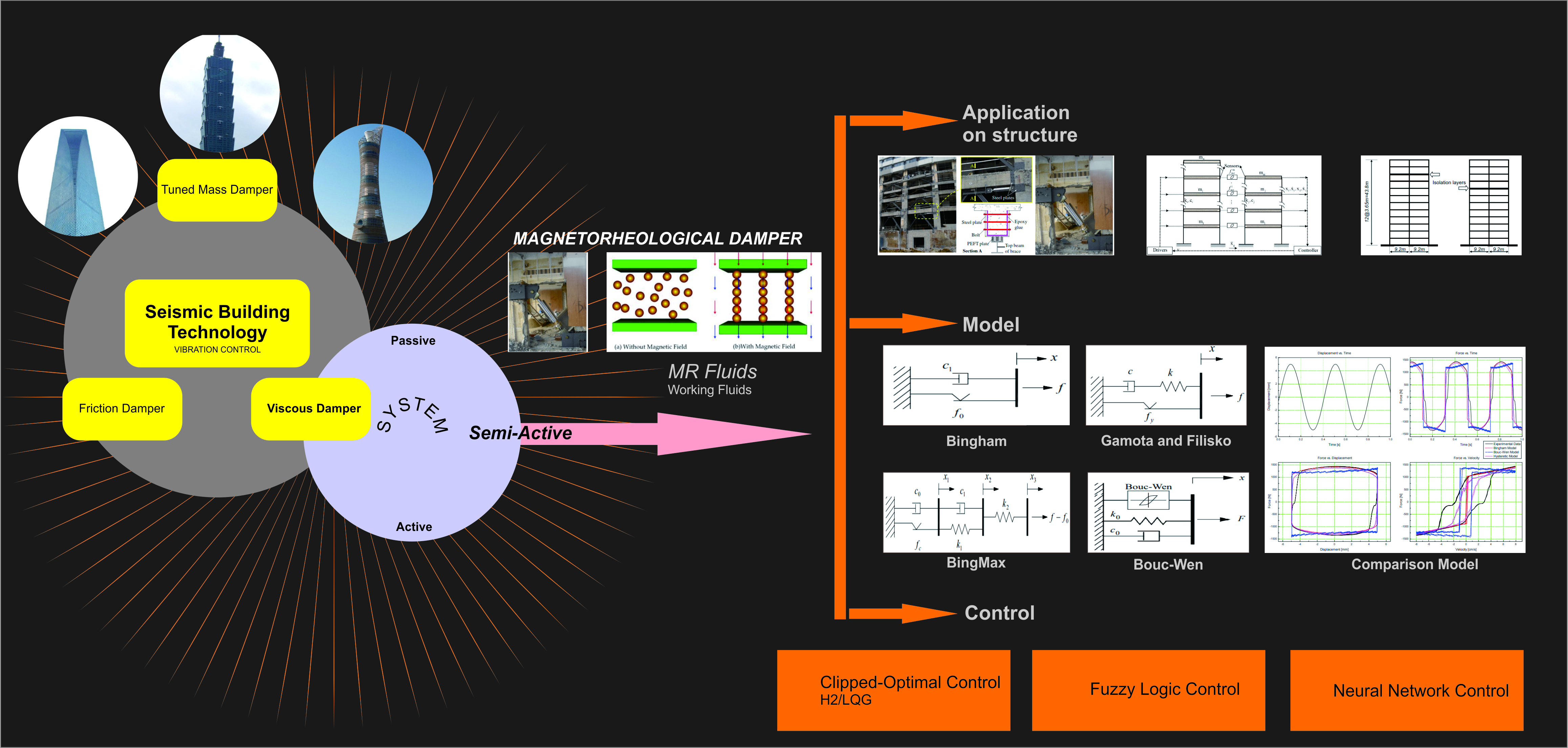
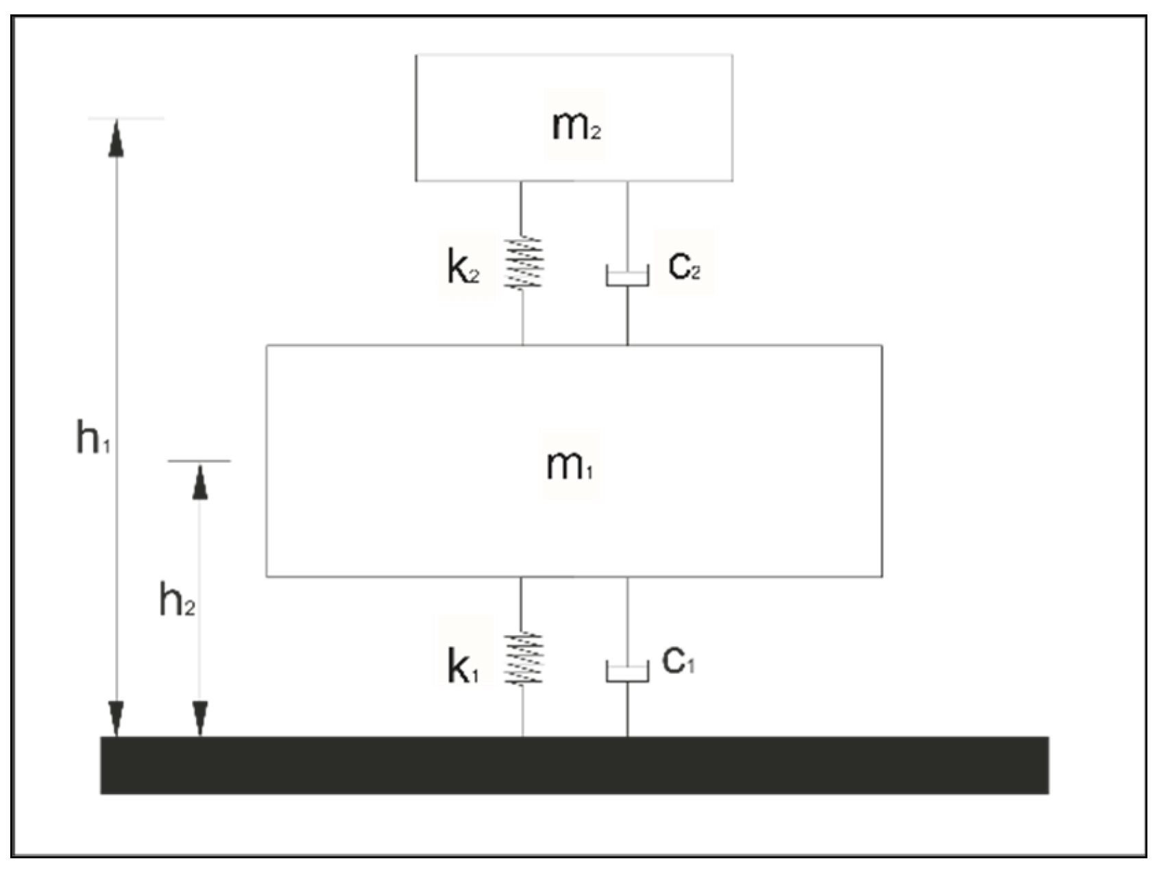
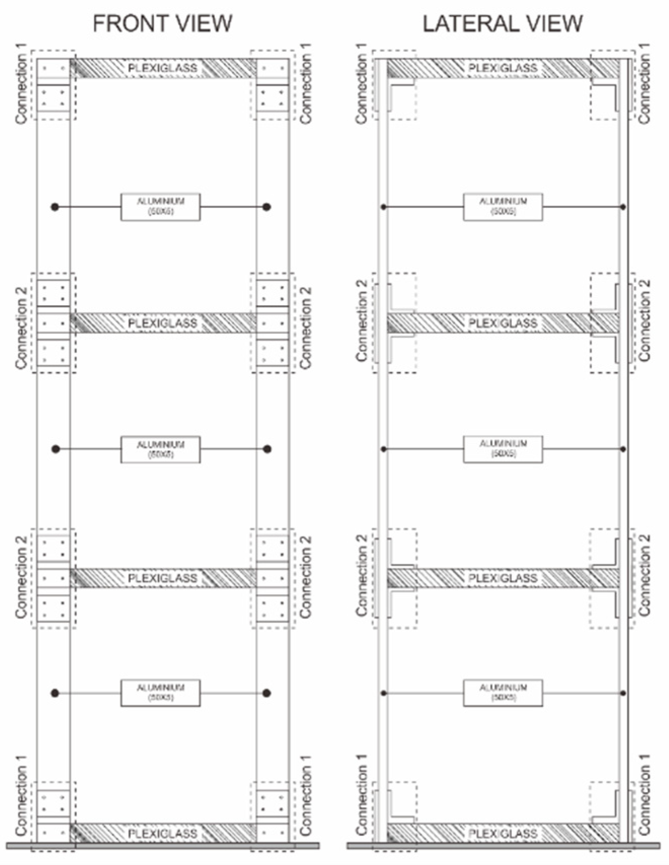
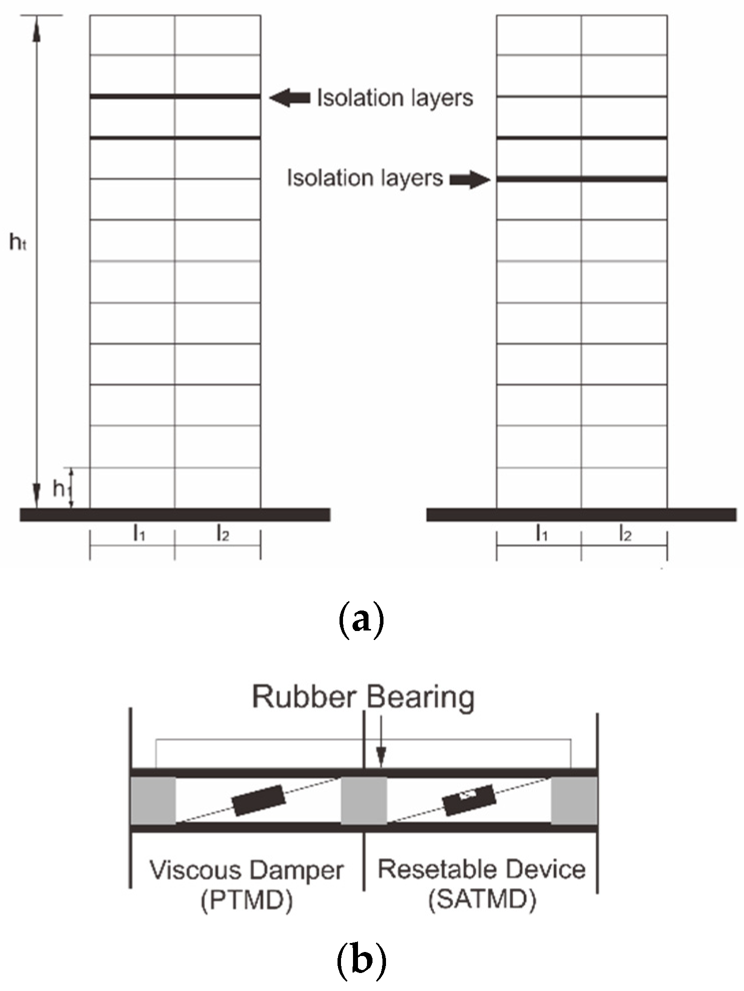
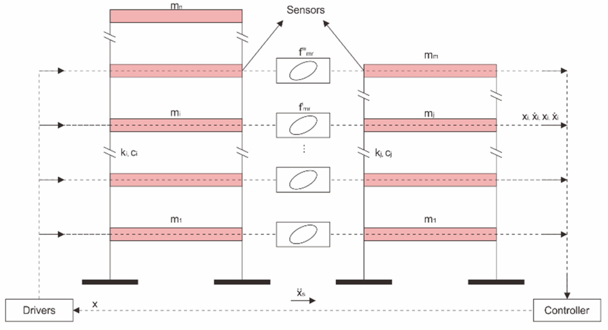
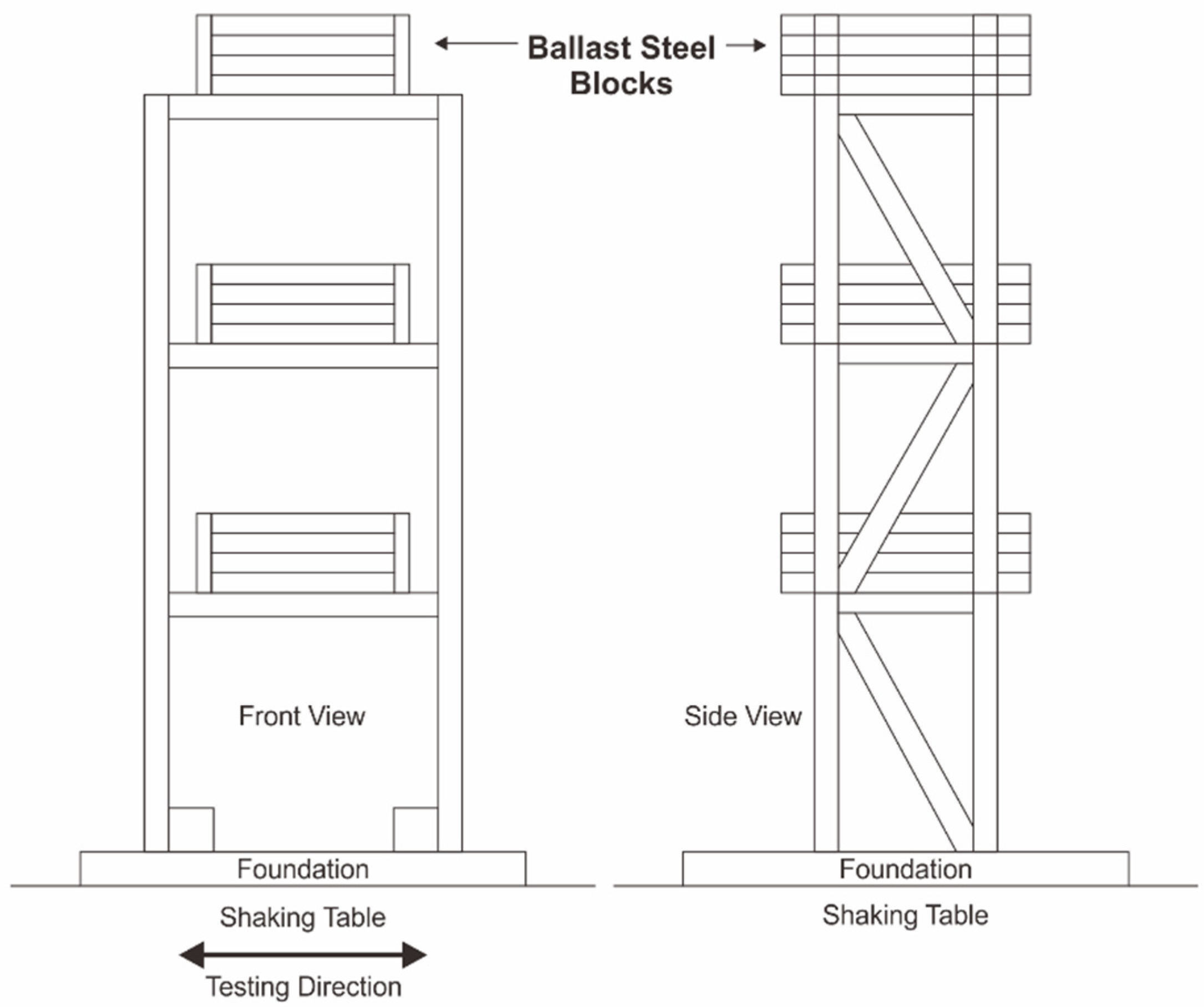
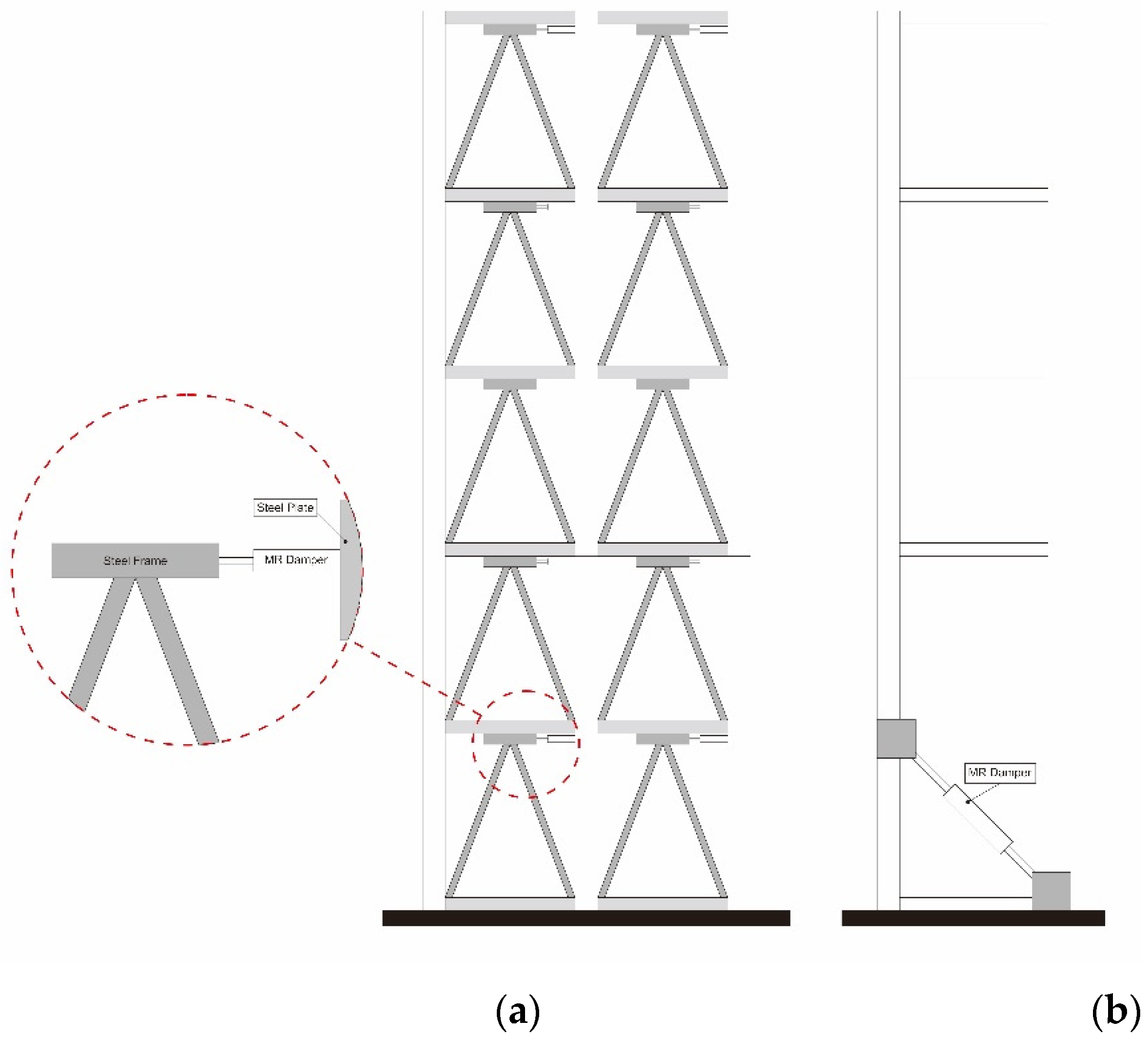
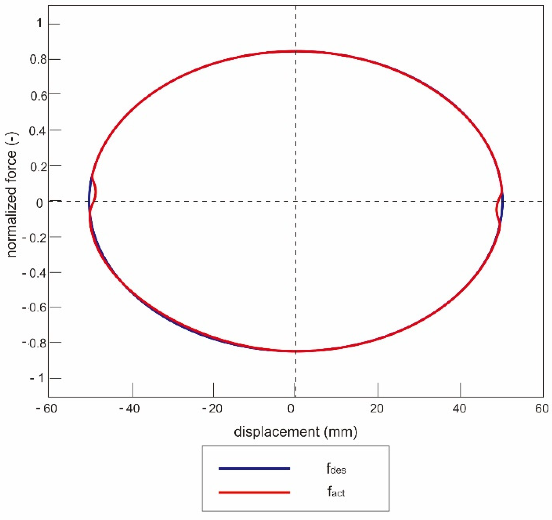
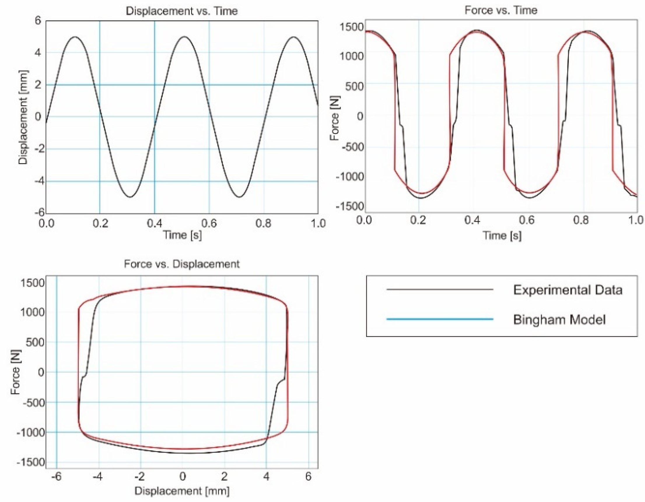
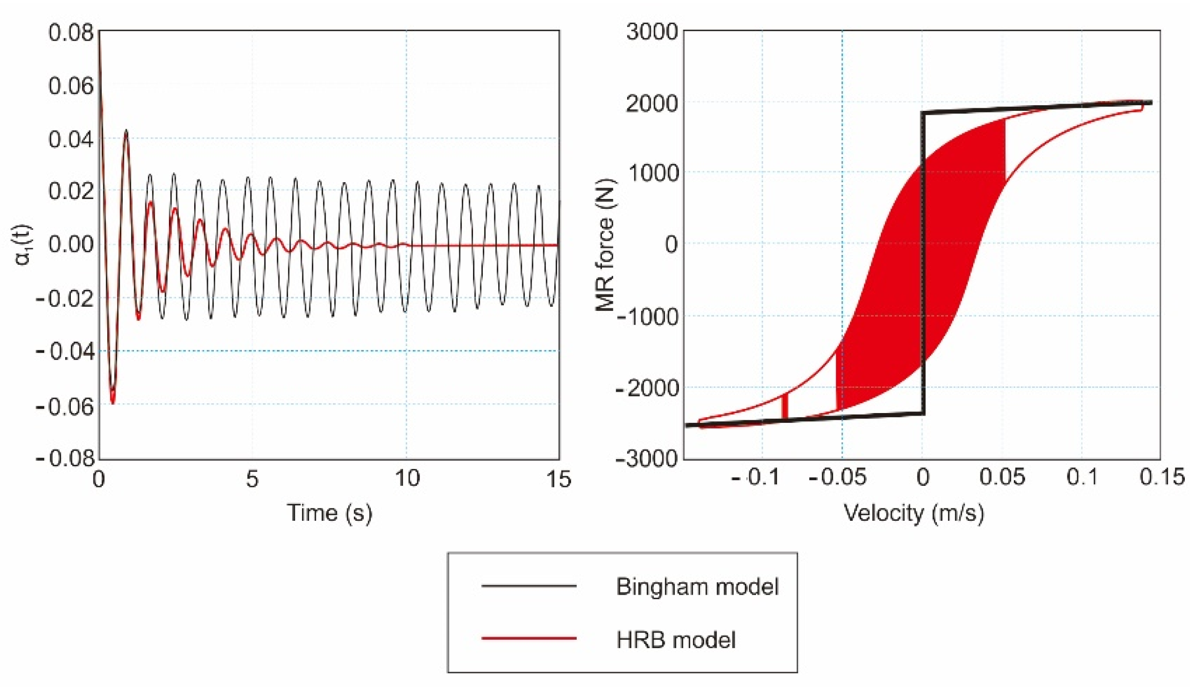
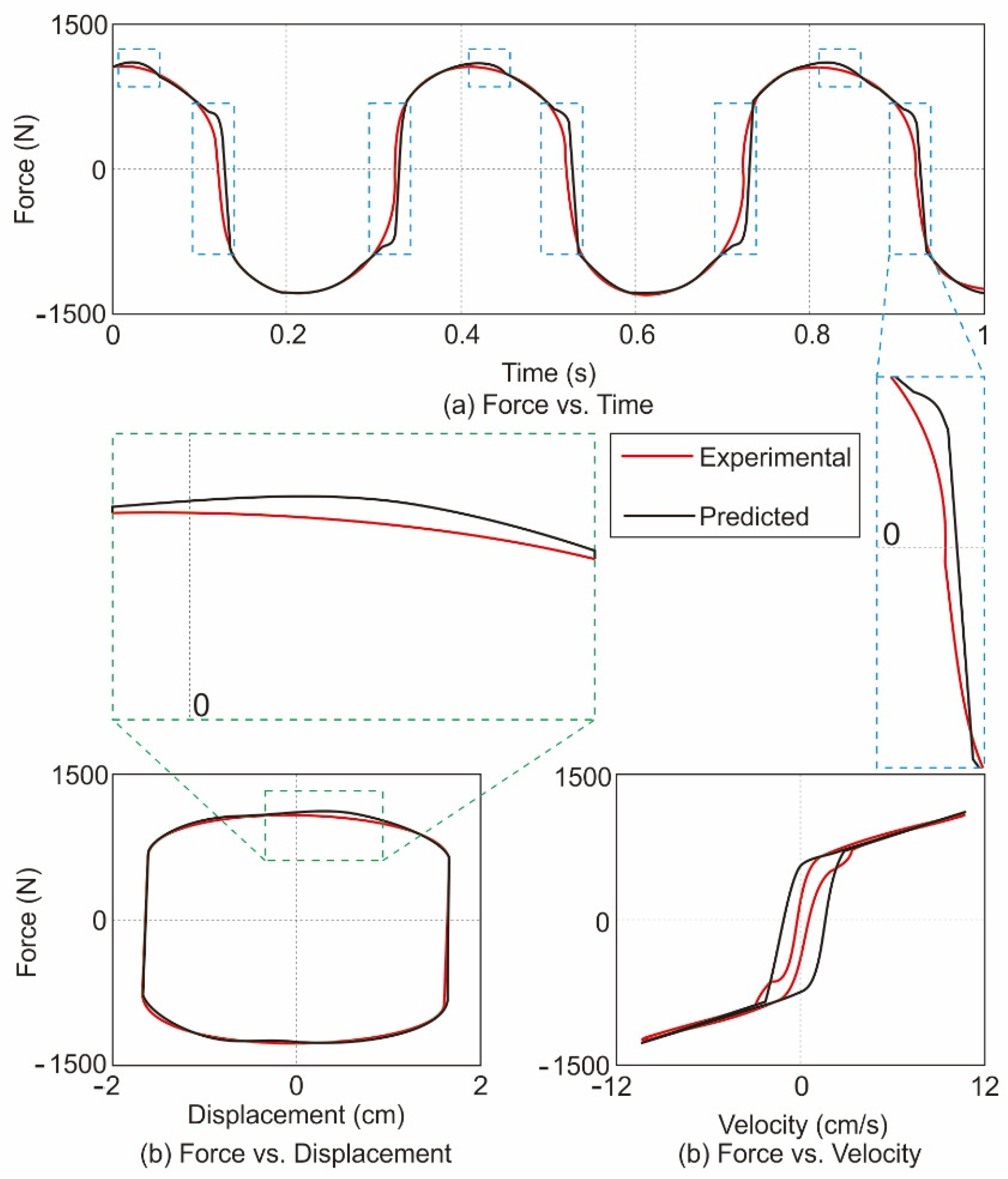
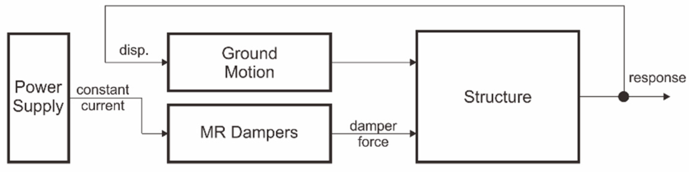
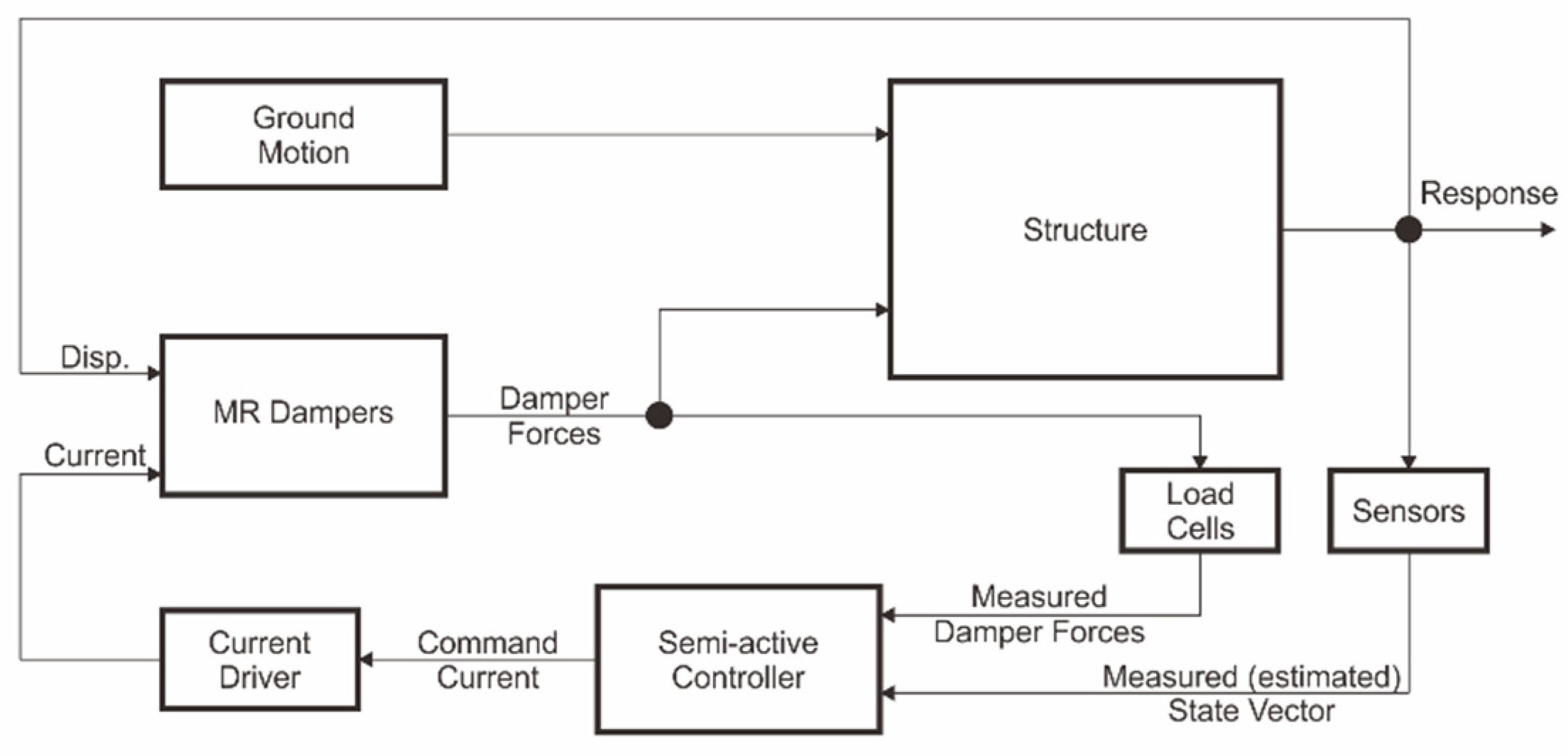
Table 1.
Basic models applied for MR dampers.
| Model | Equation | Figure |
|---|---|---|
| Bingham Model | where c1 and f0 are equal to the damping coefficient and the shear friction force, respectively; and sgn () is a function of the signum. The damping force is linearly dependent on the damper speed, while the friction force depends on the velocity [177,179]. |  |
| Gamota and Filisko Model | where c0 is the damping coefficient of the Bingham model, and k1, k2, and c1 are the coefficients of stiffness and viscous damping, respectively, in relation to the linear solid material [179,180]. |  |
| Bouc-Wen Model | k1 represents the damper stiffness of the accumulator and c0 is the dashpot coefficient associated with viscous damping at higher velocities. A dashpot c1 was included in the model to produce the roll-off observed in the experimental data at a low velocity. k0 is the stiffness control at a higher velocity, and x0 is the initial displacement of the spring k1 in relation to the nominal damper force due to the battery [180]. |  |
| BingMax Model | where a = c/k is the quotient of the dashpot c and the spring k, and fy is the friction force on the slider [180]. |  |
| LuGre Model | where g(v) is the Coulomb friction and the Stribeck effect, and f(v) represents viscous friction. |  |
Table 2.
Recently published articles on controllers for MR dampers for structural buildings.
| No. | Author and Year | Controller | Finding |
|---|---|---|---|
| 1 | Zafarani and Halabian (2020) [190] | Clipped optimal with LQG control | Control of the seismic inelastic torque response of multi-story buildings. |
| 2 | Mohebbi et. al. (2018) [191] | H2/LQG control | Modification of H2/LQG control to optimize the control system’s performance |
| 3 | Zizouni et. al. (2019) [192] | Neural network control | Efficacy of neural network control on a three-story small-scale structure using the Tōhoku 2011 and Boumerdès 2003 earthquake data. |
| 4 | Bozorgvar and Zahrai (2019) [193] | Adaptive Neuro-Fuzzy inference system | Neuro-fuzzy optimization adapted to genetic algorithms. |
| 5 | Li and Liang (2018) [194] | Sliding mode control Fuzzy system | Developed a sliding mode control method based on a fuzzy system. Fuzzy logic control mitigates the chattering phenomenon. |
| 6 | Cesar and Barros (2017) [195] | Adaptive Neuro-Fuzzy inference system | Verified the efficacy of neuro-fuzzy controllers in reducing the responses of building structures equipped with MR dampers. |
| 7 | Al-Fahdawi and Barroso (2021) [196] | Adaptive Neuro-Fuzzy inference system and Simple adaptive control | Reduction of the seismic response of three-dimensional combined buildings under two-way seismic excitation with adaptive neuro-fuzzy inference system control and simple adaptive control. |
| 8 | Mousavi (2020) [197] | Fuzzy logic controller | Use of wavelet networks and fuzzy logic controllers to copy the inverse dynamics of MR dampers and nonlinear isolators. |
| 9 | Ndemanou and Nbendjo (2018) [185] | Fuzzy logic controller | Fuzzy logic controls are better than traditional controls and algorithmic controls and are critical when optimizing the response of a structure to seismic loads. |
| 10 | Mehrkian et. al. (2017) [186] | Fuzzy logic controller | Improving a fuzzy control system with a smart multi-objective fuzzy–genetic controller produced controls that were more effective than others. |
Publisher’s Note: MDPI stays neutral with regard to jurisdictional claims in published maps and institutional affiliations. |
© 2021 by the authors. Licensee MDPI, Basel, Switzerland. This article is an open access article distributed under the terms and conditions of the Creative Commons Attribution (CC BY) license (https://creativecommons.org/licenses/by/4.0/).
Share and Cite
MDPI and ACS Style
Lenggana, B.W.; Ubaidillah, U.; Imaduddin, F.; Choi, S.-B.; Purwana, Y.M.; Harjana, H. Review of Magnetorheological Damping Systems on a Seismic Building. Appl. Sci. 2021, 11, 9339. https://doi.org/10.3390/app11199339
AMA Style
Lenggana BW, Ubaidillah U, Imaduddin F, Choi S-B, Purwana YM, Harjana H. Review of Magnetorheological Damping Systems on a Seismic Building. Applied Sciences. 2021; 11(19):9339. https://doi.org/10.3390/app11199339
Chicago/Turabian StyleLenggana, Bhre Wangsa, Ubaidillah Ubaidillah, Fitrian Imaduddin, Seung-Bok Choi, Yusep Muslih Purwana, and Harjana Harjana. 2021. "Review of Magnetorheological Damping Systems on a Seismic Building" Applied Sciences 11, no. 19: 9339. https://doi.org/10.3390/app11199339
Note that from the first issue of 2016, this journal uses article numbers instead of page numbers. See further details here.