A New Anti-Windup Compensator Based on Quantitative Feedback Theory for an Uncertain Linear System with Input Saturation


Smart Structures and System Laboratory, Department of Mechanical Engineering, Inha University, Incheon 22212, Korea
*
Author to whom correspondence should be addressed.
Appl. Sci. 2019, 9(15), 2958; https://doi.org/10.3390/app9152958
Submission received: 3 May 2019
/
Revised: 15 July 2019
/
Accepted: 17 July 2019
/
Published: 24 July 2019
(This article belongs to the Section Mechanical Engineering)
Abstract
:This paper devotes to the robust stability problem for an uncertain linear time invariant (LTI) feedback system with actuator saturation nonlinearity. Based on a three degree of freedom (DOF) non-interfering control structure, the robust stability is enforced with the describing function (DF) approach for an uncertain LTI system to avoid the limit cycle. A new type of anti-windup (AW) compensator is designed using the quantitative feedback theory (QFT) graphical method, which results in a simple design procedure and low-order AW control system. One of the most significant benefits of the proposed method is free of the non-convexity (intractable) drawback of the linear matrix inequality (LMI)-based approach. The analysis conducted on the benchmark problem clearly reveals that the proposed QFT-based anti-windup design is able to handle both saturation and uncertainty in a very effective manner.
1. Introduction
Unwanted oscillatory behavior is the most common reason for instability in many applications, especially electrical circuits. A stable oscillatory motion (limit cycle) has been observed in many practical systems, for instance, in electrical circuits and systems such as buck converters [1], Chua’s circuits [2], power systems [3], bang-bang clocks and data recovery circuits [4], and Micro-electro mechanical systems (MEMS) oscillators [5]. The intense research on the limit cycle behaviors focuses on establishing their existence, investigating their stability and bifurcations analysis [2], and so on. For single-input single-output (SISO) systems, the existence problem was investigated by the well-known describing function (DF) method from the classical control techniques [6]. The DF method leads to results which are not rigorous in nature but the empirical evidence over many decades has proven the power of the DF method. The actuator input saturation is the main reason for the limit cycle development. All actuator devices are subject to amplitude saturation [7]. For example, current, voltage, and every conceivable physical input is ultimately limited. The reliable operation and acceptable performance of most systems must be accessed in the light of actuator saturation. Anti-windup (AW) techniques have been proposed to account a priori for the presence of saturation nonlinearity. AW designs based on model-based linear matrix inequality (LMI) methods [8], Internal model control (IMC) method [9], and sector methods are becoming popular in recent years. As mentioned in [9], most of the abovementioned works assume that if the linear design is robust, then the constrained system with AW compensation will continue to be robust. However, this view was proven wrong in [10].
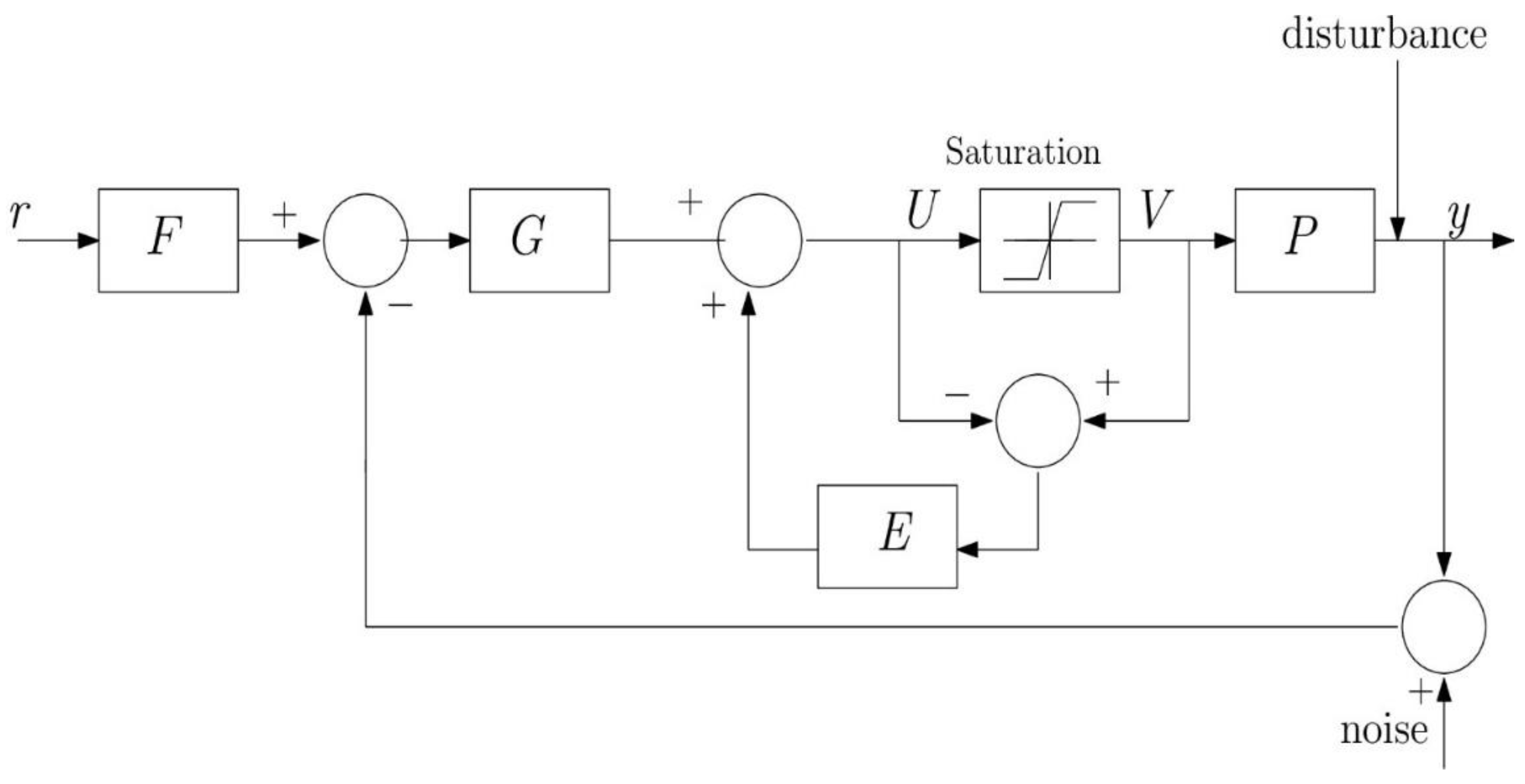
Input saturation is a common behavior, and significant nonlinearity exists in all practical control systems because of the physical limits of actuators. The saturated actuator can break the feedback loop and hence the closed-loop system becomes unstable or the limit cycle occurs. This finally degrades the performance (anti-windup) when the controller is implemented. AW design with uncertainty is a challenging problem at least in a non-conservative way. It is known that integral quadratic constraint (IQC)-based design characterizing the saturation and uncertainty is a less conservative and promising one [11]. But, in general, this approach is non-convex and thus intractable. By converting the AW problem into a graphical-style design, for the SISO systems, the non-convexity associated with an LMI-based approach is effectively and largely avoided. One such a graphical design method for the uncertain system is the quantitative feedback theory (QFT). QFT design naturally results in relatively simple design structure and low-order AW compensator which is useful from a practical point of view. To name an earlier QFT AW design approach, the describing function–based approach to analyze the limit cycle for an uncertain system is proposed in [12]. The saturation nonlinearity is replaced by an uncertain gain as part of the open-loop uncertainty and the QFT design is performed in a two degrees of freedom (2-DOF) structure as shown in Figure 1. In this figure, the uncertain system, the feedback controller, and the prefilter are denoted by P, G, and F, respectively. Moreover, the saturation input and output are represented by U and V. The 2-DOF structure does not make it possible to avoid limit cycling in a conditionally stable system. This work is extended for the 3-DOF structure in [13], similar to the one shown in Figure 2, suggested by Horowitz [14]. In this figure, C and H represent the feedback controller and the AW controller, respectively. In addition, harmonic balance and the multiplier technique are applied to analyze the limit cycle within the QFT framework in [15]. The idea is to replace the nonlinear system by an equivalent frequency locus and use it jointly with the uncertain linear systems to compute the constraint region for a stabilizing controller using the QFT loop shaping. The multiplier theory is extended for a 3-DOF non-interfering control structure in [16] as shown in Figure 3. In this figure, G and E represent the feedback controller and the AW controller, respectively. The control structures in Figure 2 and Figure 3 are equivalent, with C = G/(1 − E) and H = E/(1 + E).
Another line of QFT-based design for the anti-windup problem is based on establishing a non-overshooting condition under input saturation for uncertain systems [17]. The theory proposed by Horowitz [14] is used in [17], and the robust stability is ensured by the circle criterion and the describing function technique. In [9], the AW problem is solved in the framework of a mismatch system. Furthermore, the design step involves the nonlinear loop which determines the stability during the saturation period and the disturbance filter used to compensate the signal required to meet the ideal linear response. Excellent surveys regarding different anti-windup techniques for uncertain systems are given in [18]. In general, the existing LMI-based approaches to AW design for a system with uncertainty and saturation nonlinearity are non-convex (intractable) or at least less conservative. The difficulty in searching for the multiplier (infinite dimension) [16] and the restriction involved in designing the AW controller (pole–zero cancellation, strictly proper) [13] are the main motivation for this work. In other words, the main aim of this article is to present a QFT-based AW design to alleviate the effects (divergent limit cycle for conditionally stable system) of saturation nonlinearity in uncertain linear SISO systems using the 3-DOF non-interfering structure (direct manner).
Consequently, the technical novelty and contributions of this work are summarized as follows:
- An anti-windup control design approach is presented using the QFT method for an uncertain linear time invariant (LTI) SISO system with input amplitude saturation.
- Design constraint for the AW compensator to avoid the limit cycle and the saturation compensation are developed and translated into frequency domain bounds on the Nichols chart for synthesis purpose.
- The technical novelty is the development of the proposed method directly on the 3-DOF non-interfering control structure, shown in Figure 3, as opposed to the indirect method [13]. With this framework, the proposed method does not require any restriction on the AW controller unlike the method in [13], in which one must take care of unstable pole–zero cancellation in designing the AW controller.
The effectiveness of the proposed method is validated through a comparative work between the proposed method and existing methods [13,16] using a benchmark problem. It is found to perform better than the existing methods, in terms of lesser overshoot than [13] and faster response time as compared to [16].
The remainder of this paper is divided as follows. Section 2 states the problem, and the proposed design method for the AW controller is discussed in the same section. The proposed design approach is demonstrated on a benchmark example in Section 3 and comparisons with the existing methods are given in the same section. Conclusions are drawn in Section 4.
2. Proposed Design Method
The problem is to design the feedback controller G, the prefilter F, and an AW controller E in a 3-DOF non-interfering structure as shown in Figure 3, such that is satisfies the robust stability and robust performance in the presence of plant uncertainty and actuator saturation. A two-step design procedure is commonly used to address the above problem statement. The first step involves synthesizing G and F using the standard QFT method, ignoring the actuator saturation. Next, an AW compensator is designed using the QFT to counteract saturation when it occurs and maintain the stability/performance.
We propose a method to design the AW controller (second step) with the assumption that the G and F are designed using the standard QFT (first step). The proposed method begins with the design of the anti-windup compensator E for the non-interfering control structure. The open-loop transmission function is defined as L(s) = G(s)P(s). Define, Ln(s), the transfer function between V(s) and −U(s) when the loop is opened at the plant input, as the loop transmission around the saturation element as shown in Figure 3.
and it can be written further as,
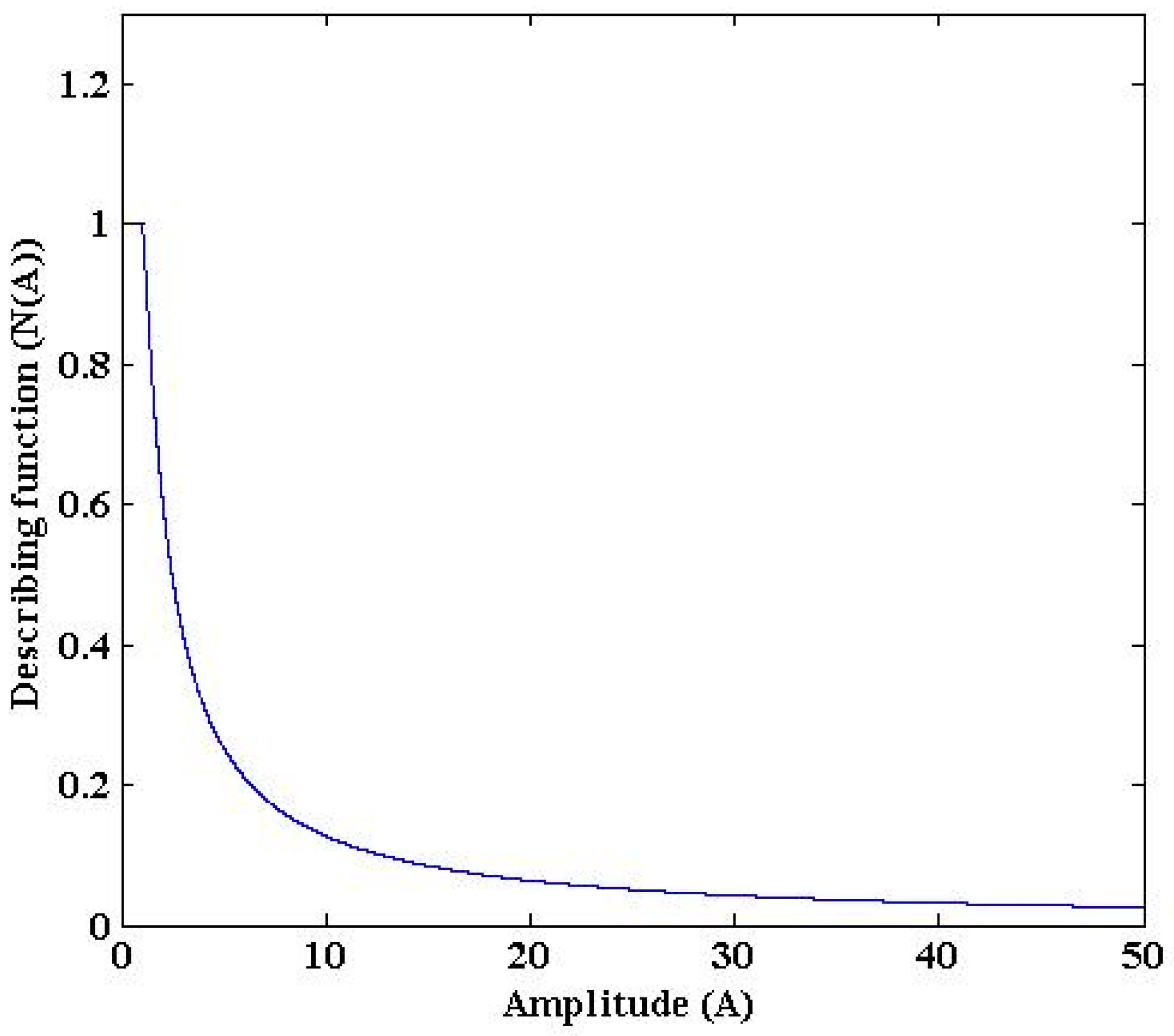
as in [13], we will also make use of describing function (DF) analysis to avoid the limit cycle. The DF of the saturation nonlinearity is shown in Figure 4 and its value is given as
where the amplitude of the input sine signal to the saturation is A and the first harmonic output is denoted as N(A). So, the saturation nonlinearity can be taken as an uncertain gain in the open-loop transmission function [13].
Ln(s) = −U(s)/V(s) = (G(s)P(s) − E(s))/(1 + E(s))
Ln(s) = (L(s) − E(s))(1 + E(s))
The condition for the limit cycle avoidance says that if the open-loop frequency function around the nonlinearity intersects −1/N(A), then the limit cycle may develop if saturation occurs [13]. This is given as follows
where N(A) is denoted as the gain uncertainty defined by Equation (3). Replacing the Ln term in Equation (4) with Equation (2) yields the following equation.
The Laplace operator ‘s’ and A associated with the N(A) are dropped hereafter unless its required. Equation (5) can be manipulated (simplified) as follows
This can be written further as,
or equivalently
This is equivalent to the sensitivity function specifications in terms of absolute value,
Following the same line of argument in [13], the right-hand side of Equation (7) is replaced by a smaller value (x dB), that is given by
The design of the anti-windup controller E such that is satisfies the above equation and the design procedure is complete. This inequality looks similar to the one in [13] but it is derived from the non-interfering control structure (similar to Figure 3) directly as opposed to the 3-DOF structure (similar to Figure 2) followed in [13] which follows G and F design first, next the anti-windup design H, and one more design element C. This simplicity brings the inherent benefit of the proposed design method.
3. Illustrative Example
This system is much studied and a challenging one to address the problem statement [13,16]. The nominal values are a0 = 0.5, b0 = 0.1 and the control input saturation limits are 1. As indicated in [11] many high-performance systems are forced to be conditionally stable. The well-known difficulty is that an unstable behavior will appear when the system is driven by large signals, which drive it into saturation [13].
The Nyquist plot of the open-loop transmission function L = PG (for 15 randomly selected plants) is shown in Figure 5 along with the −1/N(A) locus. As seen, the intersection of L with the −1/N(A) locus at some frequency illustrates that the closed-loop system may experience a limit cycle if the control signal saturates. This is confirmed in the step response (amplitude of 10) of the closed-loop system (nominal case) as shown in Figure 6a and a diverging limit cycle appears with the saturated input in Figure 6b.
Figure 7 shows the bounds for the design of an anti-windup (AW) controller (E) for x = 10 at each design frequency ω = [0.5, 1, 10]. The bounds on E are generated using the proposed inequality (Equation (8)). The AW controller (E) is shaped such that is satisfies the bounds at each chosen design frequency. Additionally, the AW controller follows the low-order structure, i.e., gain with integrator and one real pole. The designed AW controller E is given as follows.
The Nyquist plot of the closed-loop system with the designed AW controller (Equation (10)) is shown in Figure 8 and none of them intersect the −1/N(A) locus. So, the closed loop system with the designed AW controller does not develop the limit cycle even if the plant input saturates.
Figure 9 compares the step response of the closed-loop system (for 15 randomly generated plants) with an AW controller for different methods. Especially, the saturated control signals of the different methods are shown in Figure 9b. It is observed from the figures that the response time of the closed-loop system with the proposed design is faster (almost five times) than the Banos et al. method [16] and similar to the Gutman et al. method [13]. On the other hand, the overshoot is less than [13]. Therefore, it can be concluded that the benefits of the proposed method lie between existing methods showing higher stability and faster response time. It is finally remarked that in a practical problem the designer of the proposed control method must consider the balancing between conservativeness and heuristics in terms of performance enhancement of the uncertain linear system with input saturation.
4. Conclusions
The robust stability problem of uncertain linear systems with input amplitude saturation has been considered in this article. A QFT-based design method is proposed for an AW controller that guarantees the robust stability (i.e., input/output stability) of the uncertain LTI system during its nonlinear mode and avoids the problem of limit cycle using the describing function technique. Among the few methods available in the literature to consider both the robustness and saturation problem, QFT is very well suited to solve both these problems. A 3-DOF non-interfering control structure was chosen, and the design of the AW controller was carried out directly on this control structure. The proposed method has been demonstrated on the benchmark problem and compared with existing QFT-based methods. It is found that the proposed solution delivers less overshoot and/or faster response time compared with the existing methods. This is because the proposed AW design has been developed directly based on a non-interfering control structure using the DF technique. It is finally remarked that the extension from SISO to multivariable system, which is a very challenging problem, will be undertaken as a second phase of this work.
Author Contributions
R.J. derived all equations and did computer simulations to achieve performance results and S.-B.C. created the idea and made the problem formulation. In addition, both authors wrote the paper together by carefully checking the main technical contribution and sound as well.
Funding
This work was supported under the framework of the 2017 international cooperation program (GRDC-INHA IST-NASA Space Exploration Joint Research Center) through the National Research Foundation by the Ministry of Science and ICT of Korea (grant no: 2017K1A4A3013662).
Conflicts of Interest
The authors declare no conflicts of interest.
References
- Bradley, M.; Alarcón, E.; Feely, O. Design-Oriented Analysis of Quantization-Induced Limit Cycles in a Multiple-Sampled Digitally Controlled Buck Converter. IEEE Trans. Circuits Syst. I Regul. Pap. 2014, 61, 1192–1205. [Google Scholar] [CrossRef]
- Gilli, M.; Bonani, F. Analysis of stability and bifurcations of limit cycles in Chua’s circuit through the harmonic-balance approach. IEEE Trans. Circuits Syst. I Regul. Pap. 1999, 46, 881–890. [Google Scholar]
- Jing, Z.; Wang, J.; Chen, L. Computation of limit cycle via higher order harmonic balance approximation and its application to a 3-bus power system. IEEE Trans. Circuits Syst. I Regul. Pap. 2002, 49, 1360–1370. [Google Scholar] [CrossRef]
- Verbeke, M.; Rombouts, P.; Vyncke, A.; Torfs, G. Influence of Jitter on Limit Cycles in Bang-Bang Clock and Data Recovery Circuits. IEEE Trans. Circuits Syst. I Regul. Pap. 2015, 62, 1463–1471. [Google Scholar] [CrossRef] [Green Version]
- Teplinsky, A.; Feely, O. Limit Cycles in a MEMS Oscillator. IEEE Trans. Circuits Syst. II Express Briefs 2008, 55, 882–886. [Google Scholar] [CrossRef]
- Sanders, S.R. On Limit Cycles and the Describing Function Method in Periodically Switched Circuits. IEEE Trans. Circuits Syst. I Regul. Pap. 1993, 40, 564–572. [Google Scholar] [CrossRef]
- Su, Y.; Zheng, C.; Mercorelli, P. Global Finite-Time Stabilization of Planar Linear Systems with Actuator Saturation. IEEE Trans. Circuits Syst. II Express Briefs 2017, 64, 947–951. [Google Scholar] [CrossRef]
- Mulder, E.F.; Kothare, M.V.; Morari, M. Multivariable anti-windup controller synthesis using linear matrix inequalities. Automatica 2001, 37, 1407–1416. [Google Scholar] [CrossRef]
- Kerr, M.; Turner, M.C.; Villota, E.; Jayasuriya, S.; Postlethwaite, I. A robust anti-windup design procedure for SISO systems. Int. J. Control 2011, 84, 351–369. [Google Scholar] [CrossRef]
- Turner, M.C.; Herrmann, G.; Postlethwaite, I. Incorporating Robustness Requirements into Anti-windup Design. IEEE Trans. Autom. Control 2007, 52, 1842–1855. [Google Scholar] [CrossRef]
- Turner, M.C.; Kerr, M.; Postlethwaite, I. On the Existence of Stable, Causal Multipliers for Systems with Slope-Restricted Nonlinearities. IEEE Trans. Autom. Control 2009, 54, 2697–2702. [Google Scholar] [CrossRef]
- Oldak, S.; Baril, C.; Gutman, P.O. Quantitative design of a class of nonlinear systems with parameter uncertainty. Int. J. Robust Nonlinear Control 1994, 4, 101–117. [Google Scholar] [CrossRef]
- Berger, A.; Gutman, P.O. A new view of anti-windup design for uncertain linear systems in the frequency domain. Int. J. Robust Nonlinear Control 2016, 26, 2116–2135. [Google Scholar] [CrossRef]
- Horowitz, I. A synthesis theory for a class of saturating systems. Int. J. Control 1983, 38, 169–187. [Google Scholar] [CrossRef]
- Baños, A.; Barreiro, A.; Gordillo, F.; Aracil, J. A QFT framework for nonlinear robust stability. Int. J. Robust Nonlinear Control 2002, 12, 357–372. [Google Scholar] [CrossRef]
- Moreno, J.C.; Banos, A.; Berenguel, M. A QFT framework for anti-windup control systems design. J. Dyn. Syst. Meas. Control 2010, 132, 021012:1–021012:15. [Google Scholar] [CrossRef]
- Wu, W.; Jayasuriya, S. A New QFT Design Methodology for Feedback Systems under Input Saturation. J. Dyn. Syst. Meas. Control 2001, 123, 225–232. [Google Scholar] [CrossRef]
- Moreno, J.C.; Guzman, J.L.; Banos, A.; Berenguel, M. The input amplitude saturation problem in QFT: A survey. Annu. Rev. Control 2011, 35, 34–55. [Google Scholar] [CrossRef]
Figure 1.
A two degree of freedom (2-DOF) structure with actuator saturation.

Figure 2.
An interacting 3-DOF control structure.

Figure 3.
A 3-DOF non-interfering control structure.

Figure 4.
Saturation nonlinearity representation using the describing function N(A).

Figure 5.
Limit cycle condition. Here, the Nyquist plot of the open-loop system PG (for 15 randomly generated plants from Equation (9)) and the line −1/N(A) are denoted by ‘solid green line’ and ‘solid blue line with *’, respectively.
Figure 5.
Limit cycle condition. Here, the Nyquist plot of the open-loop system PG (for 15 randomly generated plants from Equation (9)) and the line −1/N(A) are denoted by ‘solid green line’ and ‘solid blue line with *’, respectively.

Figure 6.
Closed-loop system without anti-windup controller. (a) Nominal closed-loop system for a step reference r(t) = 10 × 1(t), (b) saturated control input.
Figure 6.
Closed-loop system without anti-windup controller. (a) Nominal closed-loop system for a step reference r(t) = 10 × 1(t), (b) saturated control input.

Figure 7.
Design of anti-windup controller E using the bounds generated using the proposed design inequality (Equation (8)).
Figure 7.
Design of anti-windup controller E using the bounds generated using the proposed design inequality (Equation (8)).

Figure 8.
Limit cycle condition checking. Here, the Nyquist plot of the closed-loop system for 15 randomly generated plants and the line −1/N(A) are denoted by the ‘dashed red line’ and the ‘solid blue line with *’, respectively. The Nyquist plot of the open-loop system PG is shown by the ‘solid green line’.

Figure 9.
Comparison of the closed-loop system (for 15 randomly generated plants) with anti-windup controller for different methods; (a) closed-loop system for a step reference r(t) = 10 × 1(t), (b) saturated control input.
Figure 9.
Comparison of the closed-loop system (for 15 randomly generated plants) with anti-windup controller for different methods; (a) closed-loop system for a step reference r(t) = 10 × 1(t), (b) saturated control input.

© 2019 by the authors. Licensee MDPI, Basel, Switzerland. This article is an open access article distributed under the terms and conditions of the Creative Commons Attribution (CC BY) license (http://creativecommons.org/licenses/by/4.0/).
Share and Cite
MDPI and ACS Style
Jeyasenthil, R.; Choi, S.-B. A New Anti-Windup Compensator Based on Quantitative Feedback Theory for an Uncertain Linear System with Input Saturation. Appl. Sci. 2019, 9, 2958. https://doi.org/10.3390/app9152958
AMA Style
Jeyasenthil R, Choi S-B. A New Anti-Windup Compensator Based on Quantitative Feedback Theory for an Uncertain Linear System with Input Saturation. Applied Sciences. 2019; 9(15):2958. https://doi.org/10.3390/app9152958
Chicago/Turabian StyleJeyasenthil, R., and Seung-Bok Choi. 2019. "A New Anti-Windup Compensator Based on Quantitative Feedback Theory for an Uncertain Linear System with Input Saturation" Applied Sciences 9, no. 15: 2958. https://doi.org/10.3390/app9152958
Note that from the first issue of 2016, this journal uses article numbers instead of page numbers. See further details here.