Article

Experimental and Numerical Investigation on Repairing Effect of Polymer Grouting for Settlement of High-Speed Railway Unballasted Track

1
School of Water Conservancy Engineering, Zhengzhou University, Zhengzhou 450001, China
2
National Local Joint Engineering Laboratory of Major Infrastructure Testing and Rehabilitation Technology, Zhengzhou 450001, China
*
Author to whom correspondence should be addressed.
Appl. Sci. 2019, 9(21), 4496; https://doi.org/10.3390/app9214496
Submission received: 26 September 2019 / Revised: 10 October 2019 / Accepted: 17 October 2019 / Published: 23 October 2019
(This article belongs to the Section Environmental Sciences)

Abstract

:
Uneven settlement of high-speed railway subgrade leads to the irregularity of high-speed railway line, which seriously affects high-speed train operation. The skylight point of high-speed railway operation is short and the maintenance time is limited. Therefore, how to quickly lift and repair the ballastless track slab in the subsidence section is an urgent problem to be solved in the maintenance of high-speed railways. The two-component non-aqueous reactive polymer material has the advantages of strong expansive force, fast reaction speed, and wide application range, which is extremely suitable for the repair of high-speed railway track slab subsidence and lifting. In this study, the expansion force characteristics of different density polymer materials and the stress-deformation curves at corresponding density are tested in laboratory to propose the mechanical parameters of polymer. Then, a three-dimensional finite element (FE) model of high-speed railway train ballastless-track subgrade is established based on ABAQUS. The mechanical characteristics of CRTS III ballastless track under different repair materials, different elevation, and different density of polymer grouting materials are analyzed. The results show that, under the dynamic load of the train, the stress value of polymer repairing material is less than that of cement slurry, presenting a compressive stress state, which is similar to that of the complete subgrade surface. In addition, within a certain thickness range, increasing the thickness of polymer is beneficial to reducing the difference of stress variation between polymer filling layer and complete pavement. Once beyond this range, the thickness of polymer has little effect on the force variation.

1. Induction

Unballasted track is the most important structural form of China’s high-speed railway, which has the advantages of good smoothness, good stability, long service life, good durability, and less maintenance work [1]. The ballastless track itself has a certain flexural rigidity, which has a certain resistance to the initial settlement of the lower subgrade. However, under the action of multiple factors, e.g., environment, improper construction and repeated load of high-speed train, the subgrade of unballasted track will appear uneven settlement and other disasters to a large extent. It causes stress concentration and cracks in high rigidity track slab, which leads to the decline of long-term service performance of track slab, and then affects the comfort and safety of train operation [2]. Engineering cases related to railway settlement have been reported; for instance, due to subsidence of subgrade caused by traffic loads, the train speed on Tokaido Shinkansen Line in Japan is limited. A high-speed railway in west Germany once stopped for a time due to serious damage to the roadbed after operation [3]. After 8 months of operation, the subsidence of Shanghai Metro Line 1 increased to 30–60 mm and increased by 140 mm in four years [4]. The uneven settlement of subgrade leads to the irregularity of the upper track structure, leading to the stability and safety of high-speed train operation.
At present, when dealing with the settlement problem of the unballasted track foundation of high-speed railways, the main treatment methods are the replacement and reinforcement method, the compaction pile reinforcement method, and the geosynthetic material reinforcement method. Huang et al. put forward the use of lightweight foam concrete as the roadbed filling to control the settlement of the subgrade in special soil areas and established a large-scale model of unballasted subgrade filled with lightweight foam concrete. It was found that the strength of lightweight foam concrete with target density of 500–800 kg/m3 can meet the requirements of both the static and dynamic conditions of ballastless track subgrade [5]. In order to improve the applicability and service life of ballastless track of high-speed railway, Liu et al. proposed epoxy asphalt concrete as the lower structure of railway and studied the mechanical properties of materials and structures by material test and numerical simulation, and found that all the three EACs are suitable for the high-speed railway substructure, and the EACs could improve the cracking resistance and deformability of substructure. [6]. According to the characteristics of collapsible loess foundation in Zhengxi Passenger Dedicated Company, Yao et al. studied the adaptability and effect of subgrade Pile-sheet structure, cement-soil column punching pile, cement-soil compaction pile, and CFG pile to treat collapsible loess foundation, which provided a guidance for practical engineering application [7]. Through the model test of oblique jet grouting pile with different angles, Wu et al. obtained that the bearing capacity of the composite foundation of the oblique jet grouting pile was obviously higher than that of the natural foundation, and the research results could be used for the railway base line disease treatment works [8]. Brown et al. designed a new full-scale laboratory test facility for railway track beds and founded that the settlement of geotechnical grid reinforced subgrade was reduced compared to the original subgrade [9]. Leng et al. used the geotechnical grid to reinforce subgrade and verified that the geogrid could meet the requirements of controlling foundation settlement by monitoring the settlement of foundation [10]. All of the above methods can effectively alleviate the settlement of high-speed railway subgrade. However, there are two problems in these methods. First, the repair time is long and the damage to the original structure is large, which is not suitable for the subsidence disease of the existing high-speed railway roadbed. Second, the traffic must be blocked when the roadbed is repaired, which brings a great burden to the railway line planning.
Grouting reinforcement method [11,12] not only reinforces the roadbed but also does not affect the normal traffic, which is very suitable for the application of traffic infrastructure maintenance. For the high-speed railway subgrade reinforcement and lifting, the slurry needs to have the characteristics of good expansion, high strength after consolidation, and fast condensation speed [13,14,15,16,17]. At present, the cement slurry commonly used in the engineering has the disadvantage of small expansion force and fragility after hardening, which makes the long-term use effect of roadbed repaired unsatisfactory [18,19]. In recent years, polyurethane polymer chemical slurry has developed well, which not only has the characteristics of high fluidity, high strength, and fast condensation speed but also has the characteristics of good control of expansion pressure, uniform uplift of pavement, and stable long-term use effect. Therefore, it has been widely used in road and airport runway reinforcement projects, for instance, Ren et al. determined the layout and construction of grouting holes according to the construction technology and verified that the preventive reinforcement effect of polymer grouting is good by the FWD and GPR [20]. Cheng et al. studied the polymer constraining force at channel bottom by numerical simulation and found that the degree of common pavement structure parameters based on slab corner filling polymer materials can be obtained with density of 0.303–0.372 g/cm3, density of polymer material at the edge of the plate is 0.263–0.315 g/cm3, density of polymer material at middle plate is 0.207–0.25 g/cm3 [21]. Irfan et al. investigated the influence of fuel-resistant polymer on the consistency and performance properties of asphalt binder and hot mix asphalt (HMA) mixtures and found that 1% PMB is an optimal proportion of Elvaloy in asphalt concrete mixtures, yielding maximum MR values [22]. However, the uneven settlement of high-speed railway has very high requirements on the uniform lifting and the dynamic characteristics of the roadbed after lifting. At present, there is little research on polymer grouting technology in settlement and lifting repair of high-speed railway. Only Bian et al. [23] tested the dynamic cumulative settlement of subgrade and the deformation and shrinkage of polymer under cyclic loading in large cycles through large-scale physical model tests. However, it does not involve the influence of the physical and mechanical properties of polymer specimens on settlement of high-speed railway unballasted track. Therefore, it is urgent to investigate the mechanism of polymer subsidence and uplift in railway subgrade, improve the grouting technology and theory, and provide technical support for engineering application.
In this study, considering the physical and mechanical properties of polymer filling, the obtained law is closer to reality so as to provide technical support for the selection of parameters in engineering practice. In detail, the expansion force characteristics of different density polymer materials and the stress-deformation curves at corresponding density were tested in laboratory to provide the mechanical parameters of polymer. Then, the spatial dynamics model including high-speed train, unballasted track, and subgrade was established by ABAQUS. The structural and mechanical properties of polymer lifting layers with different thicknesses and densities under train loads were analyzed. Finally, the effectiveness of polymer grouting repair was verified by comparing with the effect of cement slurry repair.

2. Experiment Description

2.1. Materials

The polymer used in this study is a locally available slurry and its rheological properties are presented in Table 1.

2.2. Experimental Equipment and Test Design

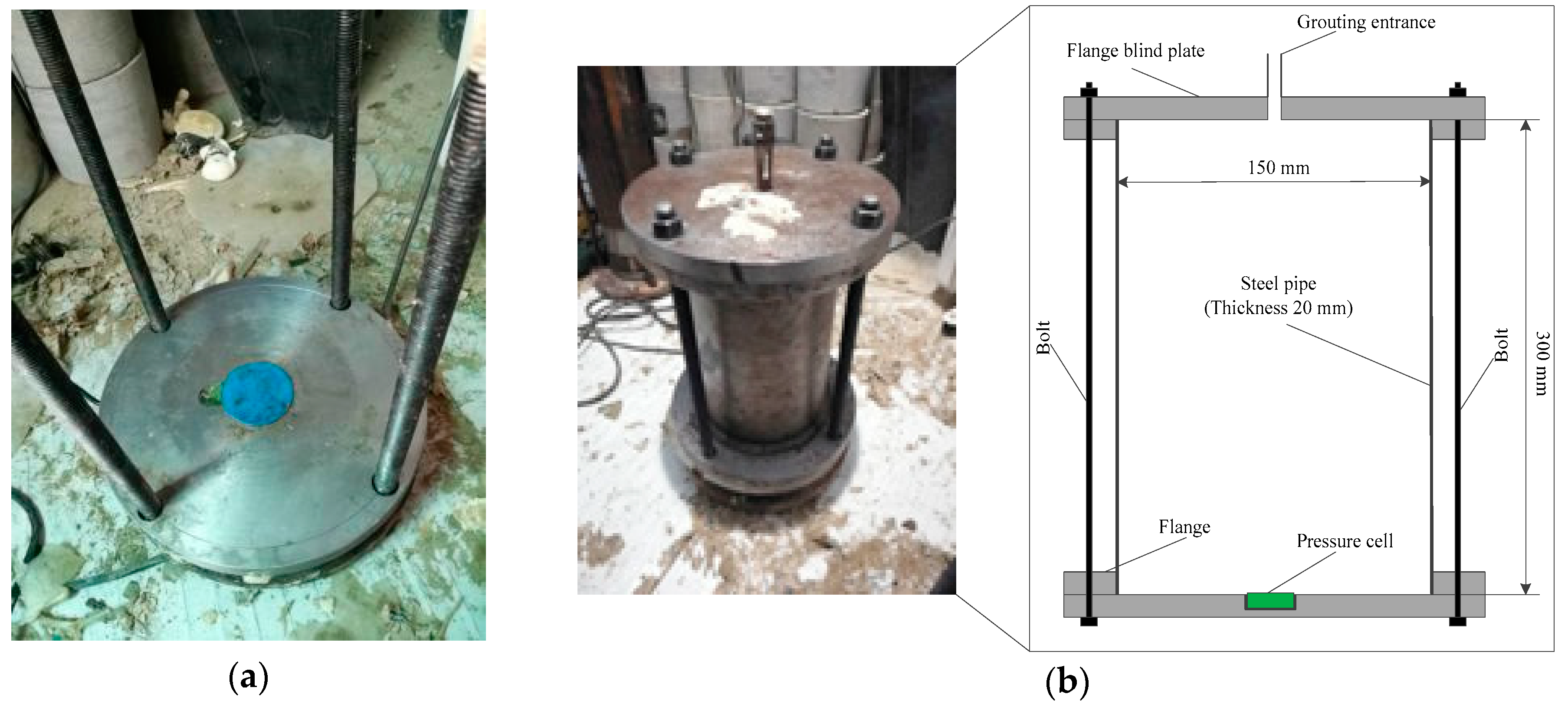
2.2.1. Experimental Equipment

The experimental equipment consists of seamless steel pipe, flange blind plate, bolt, and pressure cell. Specifically, a seamless steel pipe with a diameter of 150 mm, a length of 300 mm, and a thickness of 20 mm was used. Flanges with thickness of 20 mm were welded at both ends of the seamless steel pipe, and both ends were sealed with a flange blind plate with a thickness of 20 mm. The pressure box was mounted in a circular groove with a diameter of 26.5 mm on the bottom flange blind plate, as shown in Figure 1. Four bolts with diameter of 15 mm and length of 360 mm were used to fix and seal flange plates to form grouting containers for test. In order to prevent the pressure box from contacting the grouting material directly, a layer of high-temperature resistant silica gasket was needed between the lower flange and the cylindrical steel plate.
The pressure box produced by Nanjing Danmo Electronic Technology Co., Ltd. is used to measure the force, which has a diameter of 58 mm and a thickness of 12 mm, and the maximum range is 8 MPa. The pressure cell a strain full bridge circuit is adopted in the earth pressure box, which can accurately eliminate the influence of temperature changes on the instrument.

2.2.2. Test Design

  • Expansion Force Test
In order to ensure good sealing effect, the connecting bolts between flange blind plate and grouting barrel should be uniformly loaded when assembling the test device. In addition, in order to demold the sample smoothly after the test, butter was applied on the inner wall of the grouting container. At the beginning of grouting, the exhaust holes are opened first. Once the slurry is discharged from the vent cap, the vent cap is quickly closed. During the test, the law of expansion force change at different time is tested by pressure sensor until the pressure is stable or begins to decrease. After the test, the specimen was demolded by jacking out method, and they are marked in turn.
  • Elastic Modulus of Polymer Test
In view of the fact that the compression test of polymer grouting material referred to in this study has no current specifications to follow. In order to facilitate quantitative research, the compression test method of rigid foam plastics (GB 8813-88) [24] is used as a reference standard in this study. Three sets of cylindrical polymer specimens with diameter of 50 mm and height of 100 mm were designed in the test, and their densities were 0.246 g/cm3, 0.284 g/cm3, and 0.323 g/cm3, respectively. Considering the convenience of taking the mold, a separable high polymer sample mold was made (Figure 2). The central cylinder was designed as a pair of open structures with an inner diameter of 50 mm, a height of 600 mm, and a wall thickness of 10 mm.
The production process of the specimen was as follows: (1) A layer of grease was applied on the inner wall, bottom, and top of the mold; (2) different amount of slurry was injected into the mold to form different density samples; (3) after standing for 15–20 minutes, the mold was removed and with the specimens removed, the head and tail of the specimens are transversely cut into five specimens with a height of 100 mm on a precision lathe; (4) The density of the cut sample is calculated by weighing, and numbering them in turn, as shown in Figure 2b–d; and (5) WAW-1000 micro-computer controlled electro-hydraulic servo universal testing machine was used to load the specimen. The strain control mode was adopted, and the loading rate was set to 0.3 mm/min to simulate the quasi-static process.

3. Results and Discussion of Test

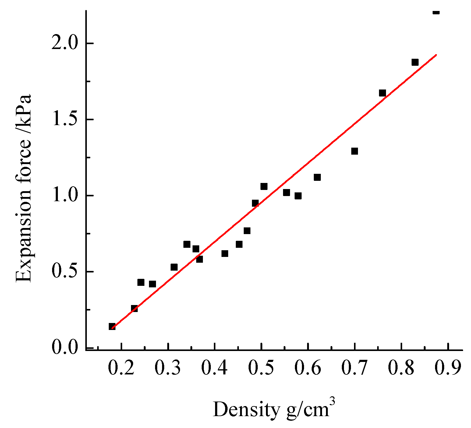
3.1. Experimental Study on Expansion Force

The density of polymer specimens in the test vessel is determined by the grouting quantity, and a different grouting quantity obtains a different maximum expansion force. Expansion force of specimens with different densities increases with time, and the relationship between the maximum expansive force and the density of different materials is obtained.

The Variation of Expansion Force with Time at Different Densities

The trend of expansive force of three typical polymers with different densities over time is shown in Figure 3. On the whole, the expansive force of polymers keeps basically unchanged with time, then increases rapidly, and finally tends to be stable.
The relationship between the maximum expansion force of polymer and the density of polymer slurry is described in Figure 4. In Figure 4, the expansive force of polymer increases linearly with the increase of slurry density. That is to say, the relationship between expansive force of polymer and slurry density of polymer is y = a + b × x (a ∈ −0.33593 ± 0.07422; b ∈ 2.58342 ± 0.14364). This is because the volume expansion of slurry increases with the increase of polymer content in the confined space, resulting in the maximum expansion force of polymer, which is consistent with the results shown in Figure 3. In part 5.1 and 5.2, considering the influence of gravity, area of material contact, and track constraint of the upper structure of gravel cushion, it takes about 0.3–0.5 MPa expansive force to lift the track slab in subsidence area, and the corresponding polymer density range is 0.246–0.323 g/cm3.

3.2. Determination of Elastic Modulus of Polymer Lift Layer

3.2.1. Process and Form of Compression Failure of Specimens

The failure modes of typical specimens with three densities are shown in Figure 5. In Figure 5, the polymer samples with different densities have certain similarities in the process of failure. At the initial stage of loading, the polymer specimens were compressed uniformly, and the surface of the specimens did not change significantly; at the slow stage of stress changes, the surface of the specimens began to fold and bulge slightly; with the continuation of loading, the specimens with density of 0.235 g/cm3 showed C-shaped deformation and bending on the whole, and the surface folding deformation was serious. When the specimens of 0.286 g/cm3 and 0.323 g/cm3 reach the limit state, macro-visible longitudinal cracks are generated along the vertical direction and develop continuously, and ultimately splitting failure occurs. The failure modes corresponding to the three densities have obvious differences, mainly because the smaller the density, the more voids in the specimen body. When the specimen body is compressed, the voids in the specimen body will be compressed first, and the deformation of the specimen is relatively large, so longitudinal cracks do not occur easily. However, the larger the density is, the fewer voids are formed in a certain space. When subjected to external pressure, the deformation process caused by pore compression is short and the deformation is relatively small. Therefore, longitudinal cracks and even splitting are prone to occur in the consolidated body.

3.2.2. Stress-Strain Curves of Specimens

According to the slope of the straight section of the specimen compression stress-strain curve (generally 10% to 30% of the peak stress is taken as the reference standard), the elastic modulus of each specimen is calculated respectively, as shown in Figure 6. In Figure 6, the elastic modulus of polymer increases linearly with the increase of slurry density. That is to say, the relationship between expansive force of polymer and slurry density of polymer is y = c + d × x (c ∈ −119.95 ± 13.87; d ∈ 884.76 ± 48.92). In parts 5.1 and 5.2, in order to simulate the backfilling of polymers, according to equation y = 884.76x − 119.95, the fitting values of elastic modulus of polymers with three densities are 97.701 Mpa, 131.322 Mpa, and 165.827 Mpa, respectively.

4. Numerical Methodology

Coupling FE Model

The high-speed railway train-unballasted track-subgrade coupling FE model was established based on ABAQUS. Because CRTS III [25] plate is used in ballastless track structure in China, Herts non-linear elastic contact is used in normal direction, and Coulomb friction model is used in tangential direction in numerical simulation.
The dynamic loading in this study is mainly divided into two parts: normal stress and tangential stress.
1. Normal stress. Wheel-rail contact is simplified to Hertz contact. The normal contact force between wheel and rail is described by nonlinear elastic of Hertz contact theory.
p ( t ) = [ 1 G Δ Z ( t ) ] 3 2
where, G is the contact constant of wheel-rail ( m / N 2 / 3 ), and its value is based on Table 2. Δ Z ( t ) is the elastic compression between wheels and rails (m).
2. Tangential stress. The tangential action of wheel-rail contact surface is realized by establishing friction model of wheel-rail. According to Kurt’s ethics, the friction between wheel and rail is equal to the product of the normal force of wheel and rail and the friction coefficient,
F = μ p ( t )
where, μ is the friction coefficient between wheel and rail,
μ = μ k + ( μ s μ k ) e β υ
where, μs is the static friction factor, μk is the dynamic friction factor, β is an exponential attenuation coefficient, and v is the relative sliding velocity between slave planes.
The high-speed railway train is simulated with multi-rigid body structure (as shown in Figure 7). The vehicle model system consists of car body, bogie, wheelset, and two-system suspension system. The car body, bogie, and wheelset are regarded as rigid bodies. In the simulation, in order to facilitate quantitative research, the elastic deformation of the car body, bogie, and wheelset during the vibration process is neglected. In addition, the primary suspension system and the secondary suspension system are simulated by connecting elements. Finally, through the connection of suspension system, the car body, bogie, and wheelset are combined to form a multi-rigid body vehicle model [26]. Two types of elements are first-order linear elements.
The CRTSIII unballasted track structure consisted of rails, fasteners, slab track, self-compacting concrete layers, and base slabs.
Eight-node reduced integration solid elements were used to simulate the rail, and connection element was used to simulate the stiffness and damping characteristics of the fastener; the rotational freedom of the end of the connection element was restrained to simulate the restraint effect of the fastener on the rail.
Solid elements of eight-node hexahedron were used to simulate the slab track. The slabs on the subgrade were connected longitudes, and the adjacent slabs were connected with steel bars. The steel bars were simulated with beam elements, and the Embedded region was used as the constraint between the steel bars and the slab track, as shown in Figure 8a. Each adjacent two track board is filled with resin mortar with a gap of 2 cm.
Two convex plates were set under the corresponding self-compaction concrete layer under each slab track, as shown in Figure 8b.
The geometric size of the convex plate was 1000 mm (transverse) × 700 mm (longitudinal) × 100 mm (depth). Limit grooves were set on the surface of the base slab to achieve mechanical limit with the convex plate of the self-compacting concrete layer, as shown in Figure 8c. Both the self-compacting concrete layer and the base slab layer are simulated by eight-node hexahedron solid element. In addition, the subgrade was also simulated by eight-node hexahedral solid elements, which was divided into three layers: the surface layer of the subgrade, the bottom layer of the subgrade, and the embankment filling.
In this study, tie constraints are used to deal with the contacts FEof CRTS III ballastless track structure, such as the contact between track slab and self-compacting concrete, the contact between self-compacting concrete and base slab, the contact between convex platform and groove, and the contact between base slab and roadbed. The material parameters and structural dimensions of the unballasted track and subgrade are shown in Table 3 [27].
Considering the influence of the constraints at the end of the rail, the running time, distance, and speed of the high-speed train on the analysis results, the longitudinal length of the track is set at 100 m. The FE model of CRTS III ballastless track structure is shown in Figure 8d.
In the process of polymer grouting repair, the repair material is injected into the joint of the base and the subgrade. The material reacts and expands, and the settled track slab is lifted and reset. After the repair is completed, a layer of polymer material is formed between the base and the subgrade. Therefore, the lifted layer of high polymer in the model was set as an area with a longitudinal length of 16.84 m and a transverse length of 3.1 m, which was located in the middle longitudinal position of subgrade just below the base, as shown in Figure 9. It is used to simulate the force characteristics of track slab, self-compacting layer, base, and high polymer material under different lifted heights of polymer and different densities of polymer. A scheme of the section whose results will be reported in each Figures is shown in Figure 9c,d.

5. Numerical Results and Discussion

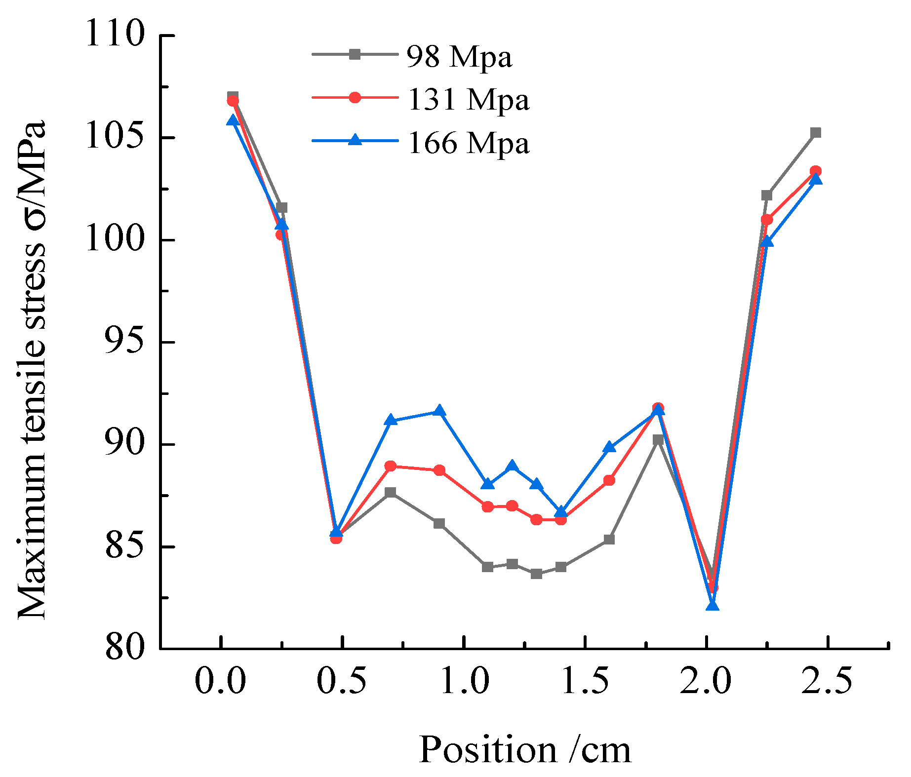
5.1. Influence of Thickness of Lifted Layer on Mechanical Properties of CRTSIII Unballasted Track Structure

Figure 10 shows the variation of stress at the bottom of track slab with different thickness of lifted layer. It can be seen that after grouting with cement-based mortar material and polymer material, the stress on the top of the track slab is similar along the cross section of the track slab, i.e., the tensile stress on both sides of the track slab is the largest, and the tensile stress is the lowest under the rail. Moreover, with the increase of lifting thickness, the tensile stress on the top of the track slab after lifting with cement mortar material decreases gradually, while the tensile stress on the top of the track slab after lifting with polymer material has no obvious change. Compared with the original complete pavement, the maximum tensile stress of the track slab after lifting with cement-based mortar material is significantly different from that of the original complete pavement, while the maximum tensile stress of the track slab after lifting with polymer material is similar to that of the original complete pavement. This is because the elastic modulus of pavement is similar to that of polymer and has good compatibility, while the elastic modulus of cement-based mortar and original pavement differs greatly.
Figure 11 shows the variation of stress at the bottom of self-compacting layer with different thickness of lifted layer. It can be seen that when cement-based mortar is used to lift subsidence area, along the cross section of self-compacting concrete layer, the tensile stress on both sides is smaller and the tensile stress in the middle is larger, which differs greatly from the bottom tensile stress of original self-compacting concrete layer of complete pavement. With the increase of the lift thickness, the maximum tensile stress on the bottom of self-compacting concrete layer decreases gradually. However, the bottom tension stress of self-compacting layer restored by polymer has little change with the lift thickness, and it is similar to the bottom tension stress of self-compacting concrete layer of original complete pavement.
Figure 12 shows the variation of stress at the bottom of base with different thickness of lifted layer. In Figure 12, when cement-based mortar is used to lift the subsidence area, along the cross section of the base, the tension stress on both sides is smaller, and the middle tension stress is larger. The overall tension stress value is smaller than that of the original complete pavement base layer. With the increase of the lift thickness, the maximum tension stress on the bottom of the base layer decreases gradually. However, the bottom tension stress of the base layer restored by polymer has little change with the lifting thickness, and it is similar to the bottom tension stress of the original complete pavement base layer.
Figure 13 shows the variation of stress at the bottom of lifting layer with different thickness of lifted layer. It can be seen from Figure 13 that the maximum tensile stress on both sides of cement slurry lifting layer is smaller, and the middle is larger. The smaller the thickness of the lifting layer is, the greater the maximum tensile stress of the cement slurry lifting layer is. The polymer lifted layer is pressed as a whole, and the compressive stress on both sides increases with the increase of the thickness of the lifted layer, and the compressive stress in the middle part changes little with thickness. Moreover, the compressive stress on both sides is large and the compressive stress in the middle is small, which is the same trend as the compressive stress on the surface of the original subgrade.

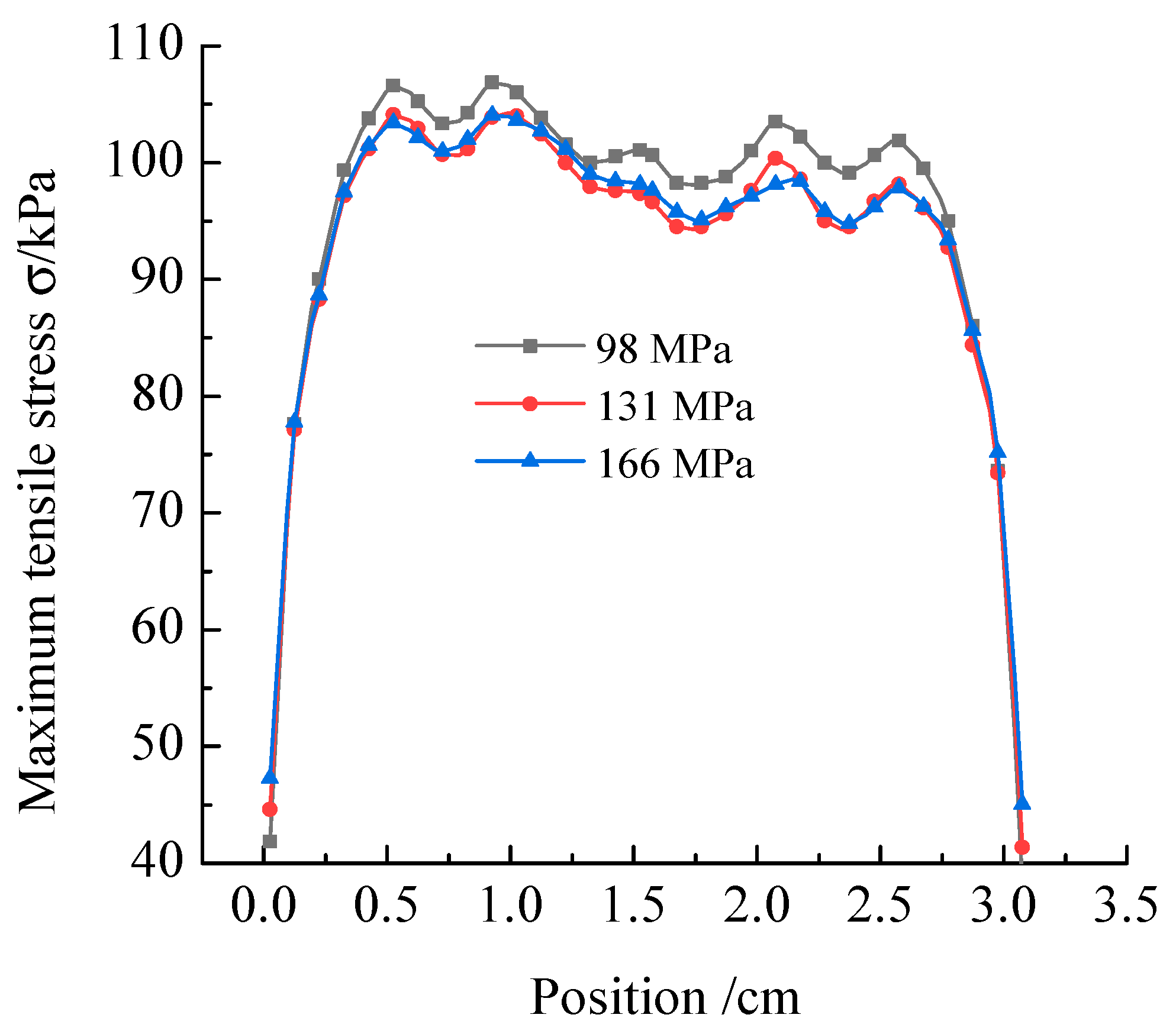
5.2. Effect of Polymer Density on Mechanical Properties of CRTSIII Unballasted Track

Due to the different load on the upper structure of the CRTSIII unballasted track in actual engineering, the expansion force of the polymer material required to lift the unballasted track structure will change, and the density of the polymer lifted layer will also change. This section analyzes the stress characteristics of unballasted track structures under different polymer density conditions. The selected lifting thickness was 30 mm, and the polymer elastic moduli were 98 MPa, 131 MPa, and 166 MPa, respectively. At the intermediate position of the CRTSIII unballasted track upper structure and the subgrade, the maximum stress at each point of the cross section of the bottom of the track slab, the bottom of the self-compacting layer, the bottom of the base, and the surface layer of the lifted layer were extracted, respectively.
Figure 14 shows the variation of stress at the top of track slab under different moduli of elasticity polymer lifting. It can be seen from Figure 14 that as the elastic modulus of the polymer material increases, the maximum tensile stress on both sides of the top of the track slab gradually decreases, and the maximum tensile stress in the middle portion gradually increases. Moreover, the maximum tensile stress on both sides is greater than the maximum tensile stress in the middle portion.
Figure 15 shows the variation of stress at the top of self-compacting concrete layer under different moduli of elasticity polymer lifting. It can be seen from Figure 15 that as the elastic modulus of the polymer material increases, the maximum tensile stress on both sides of the bottom layer of the self-compacting layer gradually decreases, and the maximum tensile stress in the middle portion gradually increases. Moreover, a numerical intersection occurs near the directly below the rails on both sides.
Figure 16 shows the variation of stress at the top of base under different moduli of elasticity polymer lifting. In Figure 16, with the increase of elastic modulus of polymer material, the maximum tensile stress at the bottom of the base layer gradually decreases.
Figure 17 shows the variation of stress at the top of lifting layer under different moduli of elasticity polymer lifting. As shown in Figure 17 that the surface layer of the lifting layer exhibits a compressive stress state. As the elastic modulus of the polymer material increases, the maximum compressive stress on both sides of the lifting layer gradually increases, and the maximum compressive stress in the middle portion gradually decreases. Moreover, the maximum compressive stress on both sides is greater than the maximum compressive stress in the middle portion.

6. Conclusions

In this study, the expansion force and elastic modulus of polymer grouting materials were tested by means of laboratory materials test. A FE model of high-speed railway train ballastless-track subgrade is established based on ABAQUS. The mechanical characteristics of CRTS III ballastless track under different repair materials, different elevation, and different density of polymer grouting materials are analyzed. The main conclusions are drawn as follows:
(1) When the cement grouting is used for lifting, the cement slurry layer is in the tension state, and the maximum tensile stress decreases as the height of the lifting increases. However, when the high-polymer grouting is used to repair and lift the settlement of unballasted track, the polymer layer is pressed as a whole, and the maximum compressive stress has no obvious change with the lift height.
(2) Compared with cement-based mortar materials, polymer materials have good coordinating deformation ability. The stress of the unballasted track structure of CRTSIII high-speed railway after polymer grouting repair is more similar to that of the original unballasted track structure.
(3) There is no strong correlation between the stress variation of CRTS III ballastless track and the thickness of polymer filling. Within a certain thickness range, increasing the thickness of polymer is beneficial to reducing the difference of stress variation between polymer filling layer and complete pavement. Once beyond this range, the thickness of polymer has little effect on the force variation of CRTS III ballastless track. From the economic point of view, too thick polymer filling layer will increase the cost of disease maintenance.

Author Contributions

Conceptualization, H.F. and F.W.; methodology, Y.S.; software, Y.S.; validation, H.F., Y.S. and X.D.; formal analysis, Y.S.; investigation, B.L.; resources, Y.S.; data curation, Y.S.; writing—original draft preparation, Y.S.; writing—review and editing, X.D.; visualization, X.D.; supervision, X.D.; project administration, H.F.; funding acquisition, H.F.

Funding

This work was supported by the National Key Research and Development Program of China (No.2017YFC1501204), the National Natural Science Foundation of China (No.51678536, 41404096), the Program for Science and Technology Innovation Talents in Universities of Henan Province (Grant No. 19HASTIT043), the Outstanding Young Talent Research Fund of Zhengzhou University (1621323001) and the Program for Innovative Research Team (in Science and Technology) in University of Henan Province (18IRTSTHN007. The authors would like to thank for these financial supports.

Conflicts of Interest

The authors declare no conflict of interest.

References

  1. Xu, J.; Wang, P.; An, B.; Ma, X.; Chen, R. Damage detection of ballastless railway tracks by the impact-echo method. Proc. Inst. Civ. Eng. Transp. 2018, 171, 106–114. [Google Scholar] [CrossRef]
  2. Ren, J.; Yang, R.; Wang, P.; Dai, F.; Yan, X. Influence of contact loss underneath concrete underlayer on dynamic performance of prefabricated concrete slab track. Proc. Inst. Mech. Eng. Part F J. Rail Rapid Transit. 2017, 231, 345–358. [Google Scholar]
  3. Yang, G.; Zhang, X.; Ying, C. Analysis of Several Questions for Express Railway Roadbed. J Shijiazhuang Railway Inst. 1998, 11, 56–60. [Google Scholar]
  4. Zhang, X.; Burrow, M.; Zhou, S. An investigation of subgrade differential settlement on the dynamic response of the vehicle–track system. Proc. Inst. Mech. Eng. Part F J. Rail Rapid Transit. 2016, 230, 1760–1773. [Google Scholar] [CrossRef]
  5. Huang, J.-J.; Su, Q.; Zhao, W.-H.; Li, T.; Zhang, X.-X. Experimental study on use of lightweight foam concrete as subgrade bed filler of ballastless track. Constr. Build. Mater. 2017, 149, 911–920. [Google Scholar] [CrossRef]
  6. Liu, Y.; Qian, Z.-D.; Zheng, D.; Huang, Q.-B. Evaluation of epoxy asphalt-based concrete substructure for high-speed railway ballastless track. Constr. Build. Mater. 2018, 162, 229–238. [Google Scholar] [CrossRef]
  7. Yao, Y.; Li, A.; Luo, Z.; Sun, Y. Study on Techniques for Collapsible Loess Foundation Treatment of Zhengzhou -Xi’an Passenger Dedicated Line. J. Railw. Eng. Soc. 2013, 9, 15–19. [Google Scholar]
  8. Wu, H.; Feng, S.; Li, C.; Dong, Z.; Wei, W. Experimental Research on the Oblique Jet Grouting Pile Composite Foundation of Existing Railway Line. J. Railw. Eng. Soc. 2018, 35, 1–8. [Google Scholar]
  9. Thom, N.H.; McDowell, G.R.; Brown, S.F.; Brodrick, B.V. The Nottingham railway test facility, UK. Proc. Inst. Civ. Eng. Transp. 2007, 160, 59–65. [Google Scholar]
  10. Leng, J. Experimental Research on the Settlement Control of a New Type of Geotechnical Grid Reinforced Roadbed Structure. J. Railw. Eng. Soc. 2017, 34, 11–14. [Google Scholar]
  11. Zhou, Z.; Du, X.; Wang, S.; Cai, X.; Chen, L. Micromechanism of the diffusion of cement-based grouts in porous media under two hydraulic operating conditions: Constant flow rate and constant pressure. Acta Geotech. 2019, 14, 825–841. [Google Scholar] [CrossRef]
  12. Zhou, Z.-L.; Du, X.-M.; Wang, S.-Y.; Cai, X.; Chen, Z. Cement grout transport within sand with fractal characteristics considering filtration. Eur. J. Environ. Civ. Eng. 2017, 23, 1497–1519. [Google Scholar] [CrossRef]
  13. Guo, C.; Wang, F. Mechanism Study on the Constructing of Ultra-thin Antiseepage Wall by Polymer Injection. J. Mater. Civ. Eng. 2012, 24, 1183–1192. [Google Scholar]
  14. Fang, H.; Li, B.; Wang, F. The mechanical behavior of drainage pipeline under traffic load before and after polymer grouting trenchless reparing. Tunn. Undergr. Sp. Technol. 2018, 74, 185–194. [Google Scholar] [CrossRef]
  15. Kennedy, J.; Woodward, P.; Medero, G.; Banimahd, M. Reducing railway track settlement using three-dimensional polyurethane polymer reinforcement of the ballast. Constr. Build. Mater. 2013, 44, 615–625. [Google Scholar] [CrossRef]
  16. Woodward, P.; Kennedy, J.; Medero, G.; Banimahd, M. Application of in situ polyurethane geocomposite beams to improve the passive shoulder resistance of railway track, Proceedings of the Institution of Mechanical Engineers. Part F J. Rail Rapid Transit 2012, 226, 294–304. [Google Scholar] [CrossRef]
  17. Liu, T.; Su, Q.; Zhao, W.; Liu, B.; Huang, J. Study on Injection-repaired and Reinforcement Effects of Subgrade Frost Boiling under Ballastless Track. J. Chin. Railw. Soc. 2015, 12, 88–95. [Google Scholar]
  18. Janeliukstis, R.; Ručevskis, S.; Kaewunruen, S. Mode shape curvature squares method for crack detection in railway prestressed concrete sleepers. Eng. Fail. Anal. 2019, 105, 386–401. [Google Scholar] [CrossRef]
  19. Zhang, Y.; Qiao, B.; Ren, W.; Wang, L. Experimental Study on Cement-improved Soil Subgrade Filling for High-speed Railway in Cold Region, Studys Collection. In Proceedings of the of the 28th National Academic Conference on Structural Engineering, Professional Committee of Structural Engineering, China Mechanics Society, Nanchang, China, 21–22 December 2019; Volume II, p. 5. [Google Scholar]
  20. Ren, Q. Research on Key Technologies of Preventive Reinforcement of Semi-rigid Base of Asphalt Pavement on Expressway, Highway Transportation Technology. Appl. Technol. Ed. 2018, 14, 54–55. [Google Scholar]
  21. Cheng, G.; Chen, P. Analysis of bearing capacity of airport pavement with polymer reinforcement subsidence. J. Civ. Aviat. Univ. Chin. 2018, 36, 47–52. [Google Scholar]
  22. Irfan, M.; Saeed, M.; Ahmed, S.; Ali, Y. Performance Evaluation of Elvaloy as a Fuel-Resistant Polymer in Asphaltic Concrete Airfield Pavements. J. Mater. Civ. Eng. 2017, 29, 04017163. [Google Scholar] [CrossRef]
  23. Bian, X.; Cheng, C.; Wang, F.; Jiang, J.; Chen, Y. Experimental study on dynamic performance and long-term durability of high-speed railway subgrade rehabilitated by polymer injection technology. Chin. J. Geotech. Eng. 2014, 36, 562–568. [Google Scholar]
  24. Ministry of Light Industry of the People’s Republic of China. GB 8813-88 Compression Test Method for Rigid Foam Plastics; China Standard Press: Beijing, China, 1988.
  25. Li, J. Quality Management and Control for Construction of High-Speed Railway CRTS III Slab Ballastless Track Engineering. Master’s Thesis, Southwest Jiaotong University, Chengdu, China, March 2013. [Google Scholar]
  26. Li, B.; Liu, X. Study on Designed Dynamic Wheel Loads of Middle-Speed and High-Speed Railways in China Based on Theory of Random Vibration. J. Chin. Railw. Soc. 2010, 32, 114–118. [Google Scholar]
  27. Xiao, W.; Guo, Y.; Gao, J.; Zhai, W. Effect of uneven subgrade settlement on the CRTS III slab track stress and deformation of high-speed railway. J. Railw. Sci. Eng. 2015, 12, 724–730. [Google Scholar]
Figure 1. Schematic diagram of the expansion force test. (a) Placement of the pressure cell; (b) Molds for testing.
Applsci 09 04496 g001
Figure 2. Schematic diagram of specimen forming process. (a) Self-made mold drawing, (b) grouting molding, (c) specimen after mold removal, (d) numbered specimens.
Applsci 09 04496 g002
Figure 3. Expansion force-time relationship curves of different densities.
Applsci 09 04496 g003
Figure 4. Variation of expansion force and polymer density.
Applsci 09 04496 g004
Figure 5. Typical failure modes of specimens. (a) The density is 0.235 g/cm; (b) The density was 0.286 g/cm3; (c) The density is 0.323 g/cm3.
Applsci 09 04496 g005
Figure 6. Variation of elastic modulus and polymer density.
Applsci 09 04496 g006
Figure 7. The vehicle model.
Applsci 09 04496 g007
Figure 8. CRTSIII unballasted track division structure and overall structure. (a) Track slab structure, (b) self-compacting concrete layer structure, (c) base structure, (d) overall structure.
Applsci 09 04496 g008
Figure 9. Location of the void. (a) Overall perspective, (b) cross-sectional perspective, (c) oblique drawing of the section, (d) horizontal drawing of the section.
Applsci 09 04496 g009
Figure 10. Variation of stress at the bottom of track slab with different thickness of lifted layer.
Applsci 09 04496 g010
Figure 11. Variation of stress at the bottom of self-compacting layer with different thickness of lifted layer.
Applsci 09 04496 g011
Figure 12. Variation of stress at the bottom of base with different thickness of lifted layer.
Applsci 09 04496 g012
Figure 13. Variation of stress at the bottom of lifting layer with different thickness of lifted layer.
Applsci 09 04496 g013
Figure 14. Variation of stress at the top of track slab under different moduli of elasticity polymer lifting.
Applsci 09 04496 g014
Figure 15. Variation of stress at the top of self-compacting concrete layer under different moduli of elasticity polymer lifting.
Applsci 09 04496 g015
Figure 16. Variation of stress at the top of base under different moduli of elasticity polymer lifting.
Applsci 09 04496 g016
Figure 17. Variation of stress at the top of lifting layer under different moduli of elasticity polymer lifting.
Applsci 09 04496 g017
Table 1. Measured properties of the tested grouts.
GroutDensity (g·cm−3)Viscosity (Pa·s)Gel Time (s)Gravity (mg/m3)
Polymer0.212.2603.14
Table 2. Contact constant value of the wheel-rail.
Tread TypeWheel of Conical TreadWheel of Abrasive Tread
Contact constant of wheel-rail G = 4.57 R 0.149 × 10 8 ( m / N 2 / 3 ) G = 3.86 R 0.115 × 10 8 ( m / N 2 / 3 )
Table 3. Structure parameters of unballasted track.
PartSize/(m)Elastic Modulus/(Pa)Density/(kg/m3)Poisson’s Ratio
Rail-2.06 × 101178500.3
Slab track5.6 × 2.5 × 0.213.65 × 101025000.2
Self-compacting concrete layers5.6 × 2.5 × 0.13.25 × 101025000.2
Base slab16.84 × 3.1× 0.282.7 × 101025000.2
Surface layer of subgrade (thickness)0.41.8 × 10820000.25
Bottom layer of subgrade (thickness)2.31.3 × 10818000.25
Embankment filling (thickness)28 × 10717000.25

