Article

Electrospun Nanofibers Embedding ZnO/Ag2CO3/Ag2O Heterojunction Photocatalyst with Enhanced Photocatalytic Activity

by
Nurafiqah Rosman
1,
Wan Norharyati Wan Salleh
1,*,
Farhana Aziz
1,
Ahmad Fauzi Ismail
1,
Zawati Harun
2,
Syamsutajri Syamsol Bahri
2 and
Kazukiyo Nagai
3
1
Advanced Membrane Technology Research Centre (AMTEC), School of Chemical and Energy Engineering, Universiti Teknologi Malaysia, 81310 Skudai, Johor, Malaysia
2
Integrated Material and Process, Advanced Materials and Manufacturing Centre (AMMC), Faculty of Mechanical and Manufacturing Engineering, Universiti Tun Hussein Onn Malaysia, 86400 Parit Raja, Johor, Malaysia
3
Department of Applied Chemistry, Meiji University, Tokyo 101-8301, Japan
*
Author to whom correspondence should be addressed.
Catalysts 2019, 9(7), 565; https://doi.org/10.3390/catal9070565
Submission received: 2 June 2019 / Revised: 19 June 2019 / Accepted: 21 June 2019 / Published: 26 June 2019
(This article belongs to the Special Issue New Trends in the Photocatalytic Removal of Organic Dyes)

Abstract

:
The immobilization of photocatalyst onto substrate has a great potential for energy-intensive separation to avoid the costly separation process and unwanted release of photocatalyst into the treated water. In this study, electrospun nanofiber composed of polyvinylidene fluoride (PVDF) with the immobilized ZnO, ZnO/Ag2CO3, ZnO/Ag2CO3/Ag2O, and ZnO/Ag2O photocatalysts were prepared via the electrospinning process. The immobilized ZnO and heterojunctioned ZnO in the PVDF electrospun nanofiber were proven via X-ray diffraction (XRD) and Fourier transform infrared spectroscopy (FTIR). The electrospinning allowed high chemical binding of the nanofiber composite with good physical interaction between the photocatalyst and the electrospun nanofiber. AFM images obtained for the nanofibers were found to be rougher than that of the pristine PVDF electrospun nanofiber. Among the photocatalyst embedded, the immobilized ZnO/Ag2CO3/Ag2O had endowed the nanofiber with an excellent photocatalytic activity and recyclability for the degradation of the RR120 under UV light irradiation. Based on the results, effective immobilization of ZnO/Ag2CO3/Ag2O in PVDF nanofiber with 99.62% photodegradation in 300 min compared to PVDF-ZnO, PVDF-ZnO/Ag2CO3, and PVDF-ZnO/Ag2O of 28.14%, 90.49%, and 96.34%, respectively. The effective ZnO/Ag2CO3/Ag2O immobilization into polymers with affinity toward organic dye pollutants could both increase the efficiency and reduce the energy requirements for water treatment via the photocatalytic application.

Graphical Abstract

1. Introduction

In the last decades, the expanding use of synthetic dyes in many industries such as textile, food, leather, paper production, hair coloring, and agriculture has been particularly noticeable, leading to increasing concern because of their widespread presence. As such, these activities compel the continual number of wastewater discharge [1]. Despite the concentration of the dye, oftentimes, the wastewaters are colored and turbid. Dyes, as well as their breakdown products and myriad others, are mutagen and harmful to human health. Consequently, approaches to curbing issues related to these lethal organic materials are instigated, as the toxic materials are being released excessively.
The photocatalytic approach is one of the approaches that are progressively addressed due to it being environmentally friendly technique, which suggests a great potential for environmental protection and energy conversion so organic pollutants can be efficiently degraded. Throughout the process, light irradiation with an increased photon energy or equal to the band gaps of the photocatalysts can be used for generation of reactive oxidation species (ROS) by semiconductor-based photocatalysts [2,3]. In the photo-mineralization of organic pollutants, zinc oxide (ZnO) titanium dioxide (TiO2), ferric oxide (Fe2O3), bismuth oxide (Bi2O3), and many others have been widely used in photocatalytic candidates, owing to its high activity due to their effective degradation efficiency of many pollutants [4,5,6,7]. Among these, ZnO and TiO2 are widely used for photocatalytic degradation of many organic pollutants due to their photochemical stability, nontoxic features and high oxidation power [8,9]. Nevertheless, the use of ZnO nanomaterials as photocatalysts is impeded due to its major disadvantages, such as limited visible light application and low quantum yields. Studies have discovered that the photocatalytic activity of the photocatalysts can definitely be improved by modifying the photocatalyst materials, such as doping with transition metals [10,11,12,13] and non-metals [13,14,15,16,17], while constituting composite photocatalysts from different semiconductors [18,19] via photo response range extension and increased efficiency in the electron-hole pair separation [20,21]. It is believed that nearly all composite semiconductors had functioned with increasing photocatalytic activity, as compared to a single semiconductor [22,23]. In previous study on the modification of ZnO via heterojunction with mixed-phase semiconductors, Ag2CO3/Ag2O exhibited better photocatalytic properties than the pristine ZnO. The Ag2CO3/Ag2O heterostructure has found a relatively low band gap energy (about 2.3 eV), which offered the ability of absorbing a broad solar spectrum, making this novel ZnO/Ag2CO3/Ag2O photocatalyst effectively functional for photocatalytic application [24].
However, in most photocatalysis studies, the post-treatment for the removal of photocatalyst in slurry form presents several drawbacks: (a) The complicated separation or filtration phases, (b) the challenging use in continuous flow systems, and (c) the particles accumulation or loss, especially in high concentrations [20]. Thus, the process becomes complicated, incompetent and costly [25]. Henceforth, the introduction regarding to photocatalytic membrane in order to support the photocatalyst has been one of outstanding technique to overcome the drawbacks. The photocatalytic membrane basically consists of separation and degradation processes. This integration concept has allowed the photocatalytic technology to take a front role for degrading the target pollutants from complex molecules to simple and less hazardous molecules. Later, the membrane separation takes place as the second role, where it allows simple and less hazardous molecules to pass through the membrane. Undeniably, the photocatalyst can be regarded as the front role, owing to benefits of minimizing the “membrane fouling” and retaining the membrane performances throughout the process [26,27]. It was reported by Lee et al. [28] that the photocatalytic membrane is compromised of the N-TiO2 membranes, creating multifunctional inorganic membranes which are capable of destroying the pollutants and self-cleaning under solar irradiation. However, most of immobilized photocatalyst suffer ineffectively within the membrane layer due to the immersion of photocatalyst in the opaque membrane layer. As a result, the photocatalyst is unable to degrade effectively, owing to the limitation of contact with light irradiation [29]. The ineffectiveness of the photocatalyst impregnated in membrane matrix is reported to be four times lower compared to photocatalyst dispersion, thus, a lowered photocatalytic performance of the membrane would be obtained [20,30].
To immobilize the photocatalyst on a suitable solid inert support with the desired morphological structure, the electrospun nanofiber has been considered as the most promising candidate due to its three-dimensional open structure, highly effective surface area, and flexibility in operation [31,32,33]. These electrospun nanofiber-based photocatalysts have the advantage of optional design nanostructures (such as solid, porous, hollow, core-sheath, hierarchical fibers, etc.) due to flexible nanofibrous structure with tunable diameters, which are easy to control and environmentally compatible [34]. Their applications in photocatalytic are expected in high photocatalytic property, attributed to its advantages of higher surface area/volume ratio [35], compared by incorporating the photocatalyst nanoparticles into the membrane. In addition, the photocatalytic membrane ensures the photocatalyst recyclability, as their fibrous structure facilitates the difficulty of powder photocatalysts’ separation from reaction mixture as previously mentioned. Therefore, fabrication of a nanofiber structure would be an effective solution to the problem of catalyst recovery [36]. Kareem et al. [37] recently reported that a visible light driven CNTs/ZnO-NH2 nanocomposite incorporated in polyacrylonitrile (PAN) nanofiber managed to degrade methylene blue and indigo carmine in a short duration of 29 and 115 min, respectively. The immobilization of GO-ZnO nanocomposite into PAN electrospun by Abdel-Mottaleb et al. [38] also exhibited an outstanding photocatalytic property toward methylene blue dye degradation under visible light irradiation. Similarly, the incorporation of Ag-AgBr@Bi20TiO32 as core shell over PAN nanofiber electrospun for herbicide isoproturon degradation offered great photocatalytic activity and recyclability under visible light irradiation [39].
Furthermore, an ideal substrate material for photocatalyst immobilization must be stable to avoid catalyst leaching, remain steady against ROS, and act selectively toward desired contaminants [40]. Numerous materials have been studied as photocatalyst supports, such as ceramic, polymers, silica, activated carbon, and alumina [41,42,43,44,45]. Fluoro-polymers, for instance, polyvinylidene fluoride (PVDF), is one of promising substrates, offering high chemical and mechanical permanency attributed to durable C−F bonds [46]. Titanium dioxide embedded PVDF nanofibers are prepared for the effective photo-oxidation of methylene blue pollution [47]. Homo assembled Ag nanoparticles on PVDF nanofibers reported a boosted photocatalytic activity of methyl orange pollutant [48]. Also, high dichlorination and photodegradation of pesticide has been studied on Ag/PAN/-g-PAA-Fe-Pd nanofiber hetero-architecture, which was prepared using PVDF/PAN nanofibers as supports and calcined for doping and grafting of C, N, and Fe–Pd elements [49].
In this study, ZnO heterojunction with Ag-based photocatalyst nanoparticles was embedded in hydrophobic PVDF nanofiber by electrospinning method. The hydrophobic nature of the composite nanofiber has allowed the capability of the photocatalyst to degrade the pollutant with the irradiation of light exposure to the nanoparticle. To the best of our knowledge, little or no documentation on the fabrication of heterojunctioned ZnO/Ag2X (Ag2X refers to Ag2CO3, Ag2CO3/Ag2O, and Ag2O)-embedded PVDF composite nanofiber for pollutant degradation is published. The pollutant degradation ability of the composite nanofiber was investigated by determining the color reduction of a model pollutant (Reactive Red 120-RR120). The phase composition, morphological structures, optical absorption, and specific surface areas were among the physicochemical properties of the prepared electrospun nanofiber that was studied. Based on the physicochemical properties and photocatalytic evaluation, the composite nanofiber in this research can be used as an effective candidate for pollutant degradation under UV light and can permit the recyclability of the photocatalytic composite.

2. Results and Discussion

2.1. Characterization of Electrospun Nanofiber
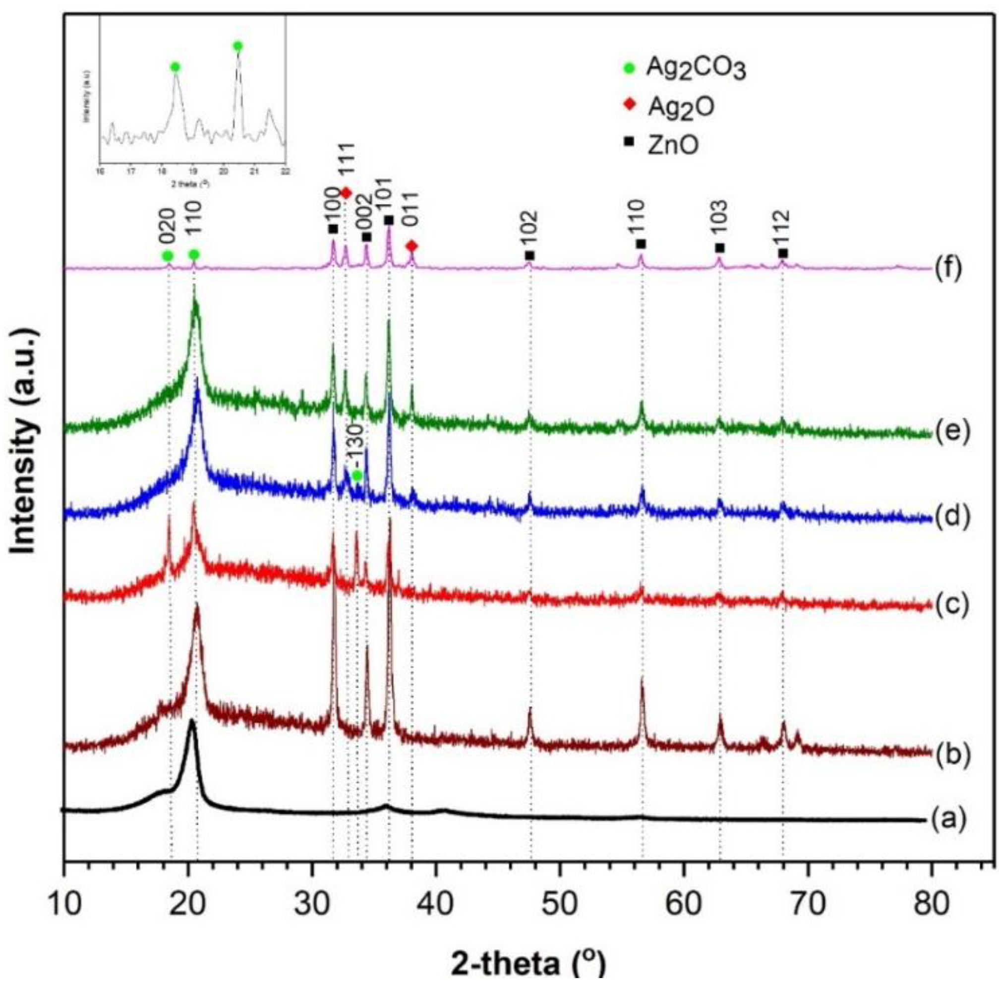
2.1.1. XRD Analysis

Figure 1 displays the X-ray diffraction (XRD) patterns, showing the crystallographic structure and phase purity of the as-fabricated samples. From Figure 1f, it is apparent that the prepared ZnO/Ag2CO3/Ag2O photocatalysts displayed the coexistence of the ZnO, Ag2CO3, and Ag2O phases. The major peaks at 2θ = (31.75°, 34.44°, 36.25°, 47.54°, 56.56°, 62.87°, 67.92 ° , and 69.06°) were assigned to the diffractions of the (100), (002), (101), (102), (110), (103), (112), and (201) characteristic peaks with hexagonal structure of ZnO, as indexed in JCPDS no. 05 0664 [50]. The other series of diffraction peaks at 18.54° and 20.54° corresponded to the (020) and (110) planes of monoclinic phase Ag2CO3 (JCPDS 26-0339) [51]. In addition, the diffraction peaks at 32.79° and 38.07° could be indexed to the (111) and (011) planes of cubical Ag2O phase (JCPDS41-1104) [52]. As shown in Figure 1a, the pristine PVDF nanofiber demonstrated only one broad diffraction peak between 15° and 25°, representing its amorphous form. For the embedded photocatalyst electrospun in Figure 1b–e, the prepared sample showed the diffraction peaks in accordance with the impregnated photocatalyst. As shown in Figure 1b, the incorporation of ZnO in PVDF nanofibers is indicated by the diffraction peaks that are perfectly indexed to ZnO. As observed in Figure 1c, the diffraction peak of ZnO/Ag2CO3 incorporated in the PVDF polymer nanofiber are well-indexed, indicating the presence of ZnO and Ag2CO3. However, there was an additional peak present at 33.67°, ascribing to the reflections of (−130) planes of the Ag2CO3. These inexistence of (−130) plane was due to the synthetization route of ZnO/Ag2CO3/Ag2O (Figure 1f) that undergoes a low temperature calcination process, causing the Ag2CO3 to be thermally unstable. The Ag2CO3 phase had partially decomposed into Ag2O during the calcination process. Therefore, the phase crystallinity of Ag2CO3 in Figure 1d,e was reduced in accordance to the phase transformation of Ag2CO3 into Ag2O, forming heterojunction with Ag2CO3/Ag2O mixed phase over the ZnO photocatalyst [53]. This would result in an improved electron-hole separation via the smooth charge transfer process, compared to the ZnO/Ag2CO3 and ZnO/Ag2O. Moreover, Figure 1d demonstrated that the diffraction peaks of Ag2CO3, Ag2O, and ZnO are well-incorporated into the PVDF electrospun nanofiber matrix. As observed in Figure 1e, ZnO and Ag2O phases were clearly observed. The invisible Ag2CO3 phase in Figure 1e showed that the Ag2CO3 has completed transformed into the Ag2O phase.

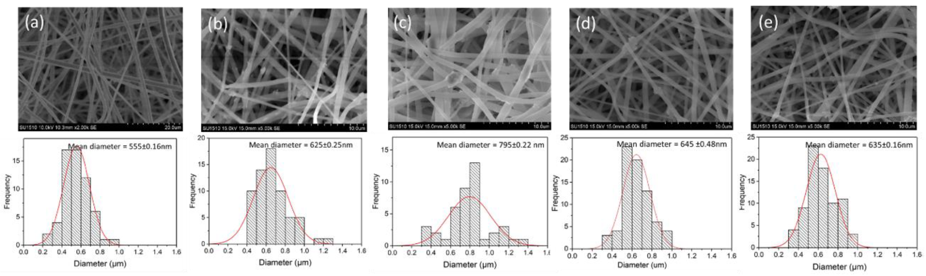
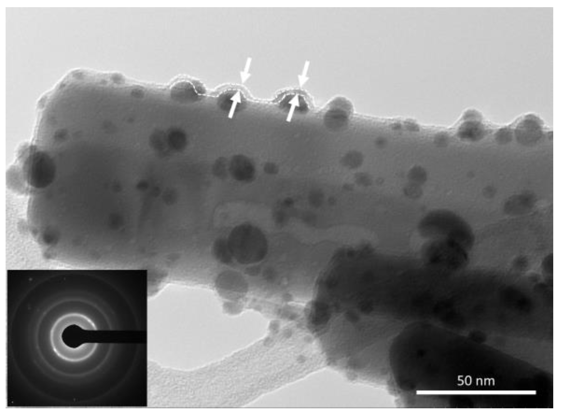
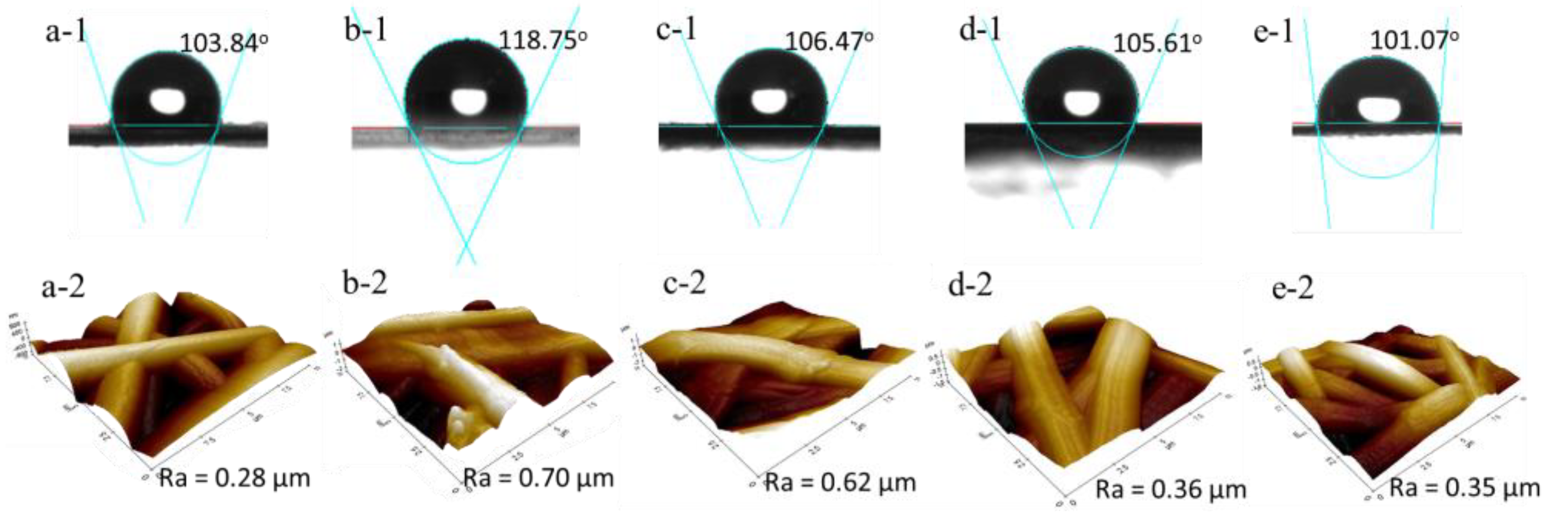
2.1.2. Morphological Structure Analysis

The morphological structure and corresponding histograms of the electrospun nanofiber diameter distribution exhibited tremendous difference, compared to the pristine PVDF electrospun nanofiber (refer to Figure 2). It can be clearly seen that the diameter of the prepared electrospun nanofibers were in the range of 500—800 nm. As shown in Figure 2a, the surface of the pristine PVDF electrospun nanofibers is relatively smooth and uniform in diameter, indicating that the parameters used in the electrospinning process were appropriate. Figure 2b–e revealed that the immobilized photocatalyst resulted in the rough surface of the nanofibers. It displayed the existence of ZnO nanorods structure interposed inside the produced nanofiber structures. The results also indicated that the diameter of the nanofibers increased, as the ZnO and ZnO heterojunctioned photocatalyst was embedded. This is due to the effect of the dope solution viscosity. The dope viscosity could be altered by increasing the polymer concentration or by inclusion of insoluble filler (ZnO or ZnO heterojunctioned) [40,54]. Overall, all of the as-spun nanofibers generated the construction of an open three-dimensional (3D) network, which offers a high surface area and flexible surface functionalities that can promote good contact with the organic pollutants for photocatalytic activity.
The distribution of the photocatalyst on the electrospun fibers in PVDF-ZnO/Ag2CO3/Ag2O nanofiber was further studied by TEM images (Figure 3). The granule and dark shade on the TEM images indicated the presence of ZnO/Ag2CO3/Ag2O particles, while the light shade bound the photocatalyst particles is the PVDF fiber. From Figure 3, the ZnO/Ag2CO3/Ag2O particles were found homogenously distributed in PVDF nanofiber. The TEM image displayed a curved layer at the edges of ZnO/Ag2CO3/Ag2O particles, revealing that the photocatalyst was enclosed with a layer of PVDF polymer. The selected area electron diffraction (SAED) pattern (the inset in the lower left) of nanofiber composite displayed multiple bright spots rings, indicating the crystalline structure of ZnO/Ag2CO3/Ag2O nanocomposite was persevered after incorporated in PVDF fiber.
The surface morphologies of the electrospun nanofibers were further evaluated by AFM, as shown in Figure 4a-2–e-2. It is revealed that the surface roughness of the PVDF electrospun nanofiber impregnated with photocatalysts was considerably higher than that of the pristine PVDF electrospun nanofiber. Based on the contact angle result, the PVDF-ZnO nanofiber displayed the highest value of 118.75° in Figure 4b-1. The incorporation of ZnO nanorod particles interposed inside PVDF nanofibers led to the hydrophobization of the nanofibers, which induced the rougher surfaces [40], as presented in Figure 4b-2. In fact, the AFM results of PVDF-ZnO displayed the roughest average surfaces toward others. Thus, this situation led to a higher physical repulsion toward water droplets that generate hydrophobic properties [55,56,57]. However, the hydrophobicity of the PVDF nanofiber decreased as the ZnO heterojunction with Ag-based photocatalyst was introduced. The AFM result depicts the value of surface roughness that decreased from 0.70 to 0.35 μm. A similar trend found that the wettability behavior of the fabricated electrospun nanofiber showed a reduced contact angle, as shown in Figure 4c-1–e-1. This is due to the presence of beads-on-string morphology, reducing the surface roughness of the nanofiber, hence developing electrospun nanofiber with lower physical repulsion toward the water droplets, thus having lower hydrophobization.

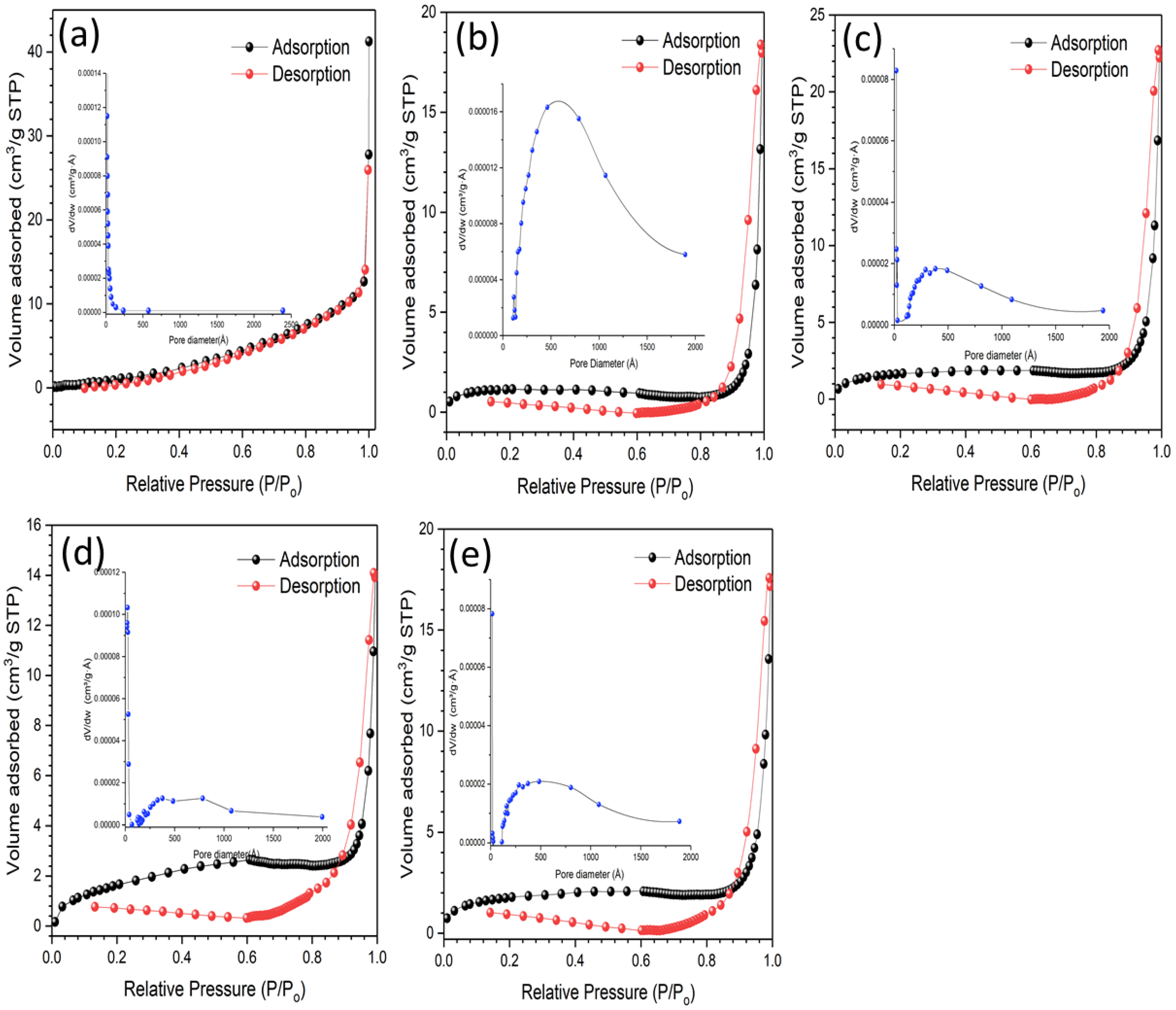
2.1.3. Surface Area and Pore Size Distribution

The nitrogen sorption porosimetry measurements were utilized to acquire information on the specific surface area and pore properties of the prepared PVDF electrospun nanofibers. Table 1 summarizes the specific surface area, pore volume, and average pore size of all the prepared PVDF nanofibers. To attain a photocatalyst with optimized photocatalytic performance, greater specific surface areas and larger pore volumes are necessary. The physical features proposed a great number of surface-active sites that support a high absorption rate and displace the reactant molecule through the interconnected porous framework. When the photocatalyst was embedded, the BET specific surface area was shown to have increased. This conclusion could be regarded by the mutual competition between the nanofiber surface roughness (Figure 4) and the thickening of the nanofiber diameter (Figure 2).
The IUPAC classification can be used to analyze the types of nitrogen adsorption-desorption isotherms [58]. As shown in Figure 5, the shapes of nitrogen adsorption-desorption isotherms of samples P0 were depicted as Type III. Meanwhile, P1, P2, P3, and P4 demonstrated a Type IV curve with a H3-type hysteresis loop and with mesoporous materials characterization [59]. Other than that, the abrupt increment in the N2 uptake at high relative pressures (P/P0 > 0.9) described the presence of macropores [60]. The outcome established that the embedded heterojunction photocatalyst displayed the hierarchical macro- and mesoporous structure. Figure 5a–e shows the corresponding BJH pore size distribution curves. It was found that the pore size of the pristine PVDF nanofiber fell less than 200 nm, while the pore size of the PVDF nanofiber incorporated with photocatalyst increased up to 500 nm. This indicated that the mesopores and macropores were observed in the PVDF-ZnO composite nanofibers. The enhanced BET surface area and hierarchical pore architecture of the PVDF-ZnO composite nanofibers have facilitated the surface absorption of reactants and mass transfer of degradation products.

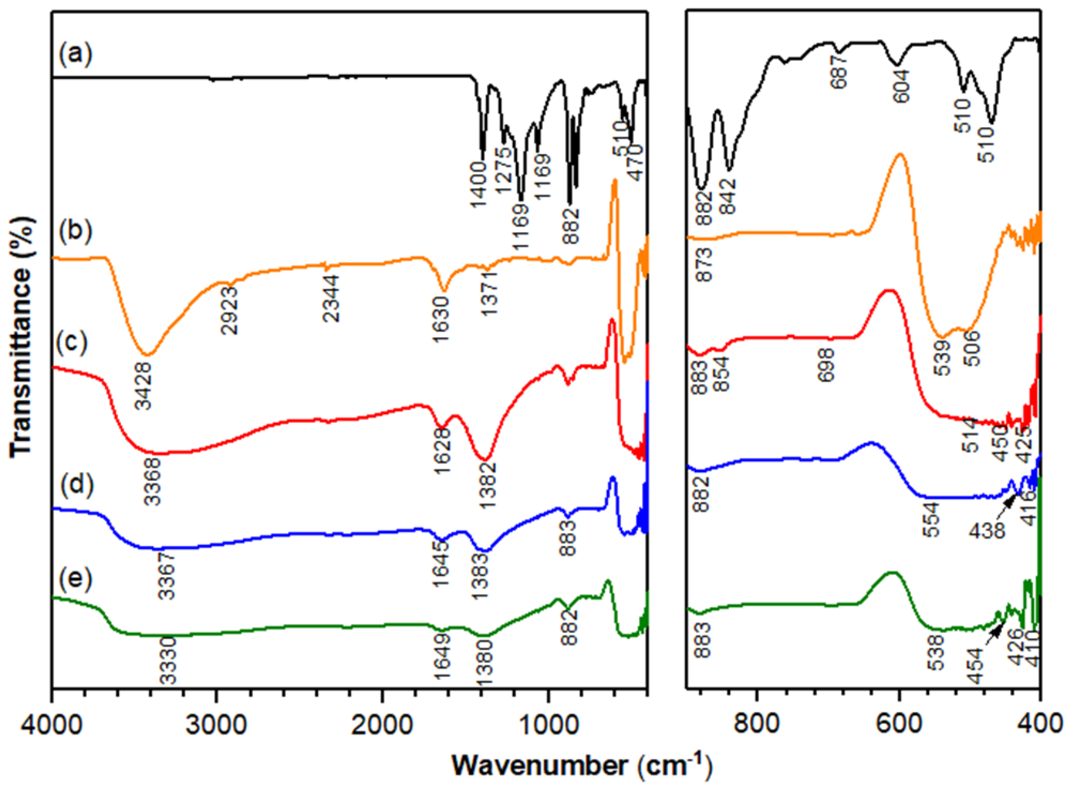
2.1.4. FTIR Analysis

The incorporation of ZnO in PVDF nanofiber can be further proven by Fourier transform infrared (FTIR) spectroscopy analysis. Figure 6 illustrates the FTIR spectra of PVDF, PVDF-ZnO, PVDF-ZnO/Ag2CO3, PVDF-ZnO/Ag2CO3/Ag2O, and PVDF-ZnO/Ag2O nanofibers. The results indicated that the PVDF spectra follows similar trends, as reported in a previous study [61]. The main peaks of ZnO, Ag2CO3, and Ag2O appeared, suggesting that the structural integrity of ZnO/Ag2CO3, ZnO/Ag2O, or ZnO/Ag2CO3/Ag2O persist, abounding even when incorporated in PVDF nanofiber. It could distinguished that a broad band, located in the range of 3000 to 3700, was ascribed to the stretching vibration of –OH group in ZnO [62]. Furthermore, as compared to PVDF-ZnO, it was observed that O-H stretching absorption peaks shifted from the high to low absorption peaks in PVDF-ZnO/Ag2CO3 and PVDF-ZnO/Ag2O. This might be due to the strong interaction between the hydroxyl group of ZnO particles either with hydrogen bond interaction of CO32− or Ag-O bonds in Ag2CO3 and Ag2O, respectively [63]. Besides, all of the embedded heterojunctioned photocatalysts in nanofiber show characteristic features of CO32− and Ag-O stretching vibration modes with absorption bands around 1630–1650 cm−1 [64,65]. Meanwhile, the broad peaks from 1500 to 700 cm−1 prove that the mixture of Ag2CO3 and Ag2O was formed in the PVDF-ZnO/Ag2CO3/Ag2O nanofiber [66]. Overall, the main absorption peaks of Ag2CO3, Ag2O and ZnO were all observed, indicating a strong interaction of photocatalyst impregnated in PVDF nanofiber.

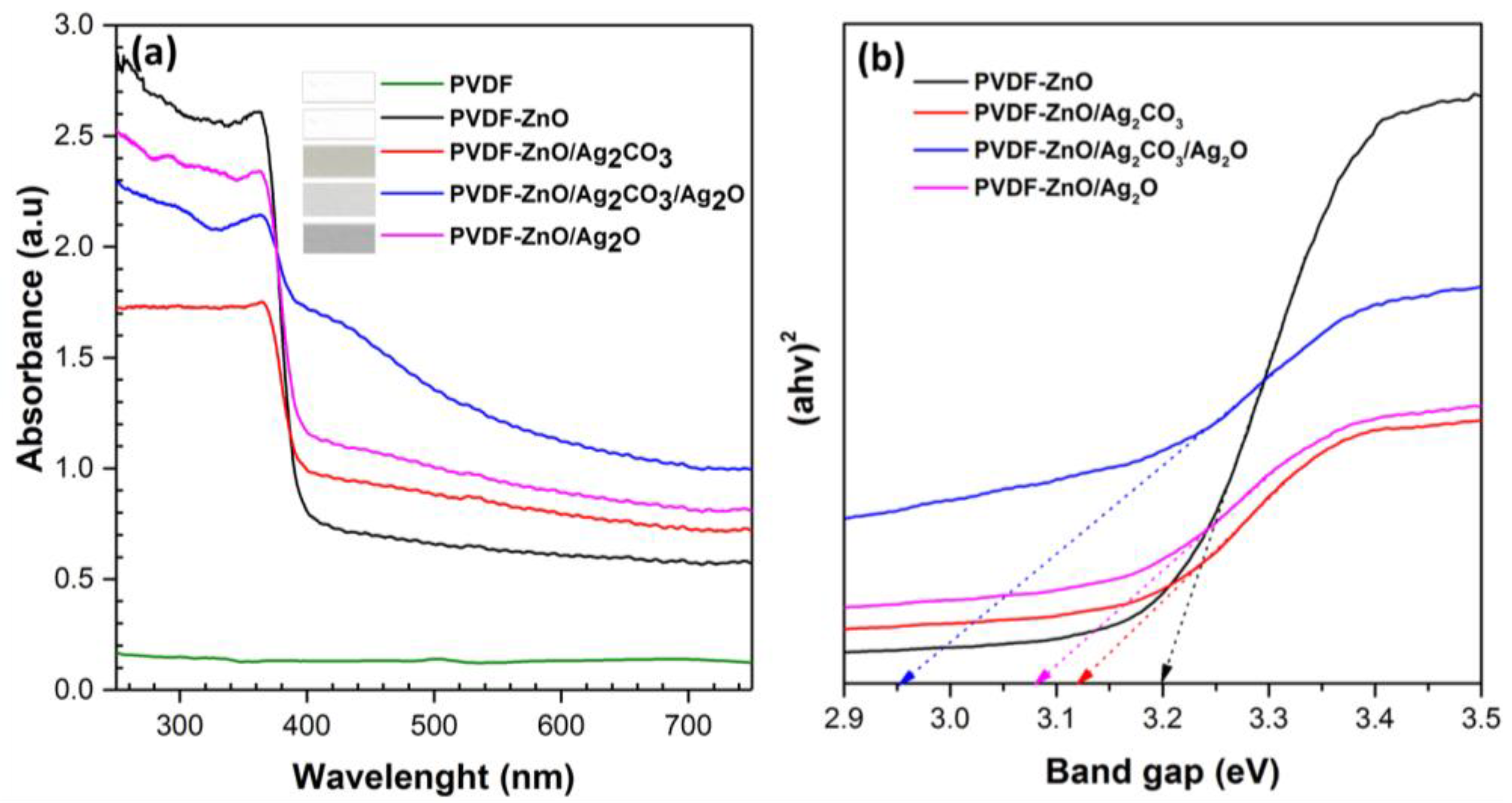
2.1.5. Optical Properties

Optical properties were determined by characterizing the response of electrospun nanofibers towards electromagnetic radiant energy, including visible and ultraviolet (UV) light. The optical properties of all of the prepared nanofibers were analyzed using UV–Vis spectroscopy, as shown in Figure 7a. It was observed that the pristine PVDF electrospun fiber mats showed very weak absorption across the wavelength, hence the band gap energy of pristine PVDF could not be presented. Meanwhile, all the embedded heterojunctioned photocatalysts in the PVDF nanofibers demonstrated an excellent optical response toward UV and visible light irradiation.
In comparison to the PVDF-ZnO nanofiber, the absorption edge shifted toward visible light range in the UV–Vis light spectrum, thus revealing the capability of the ZnO heterojunctioned photocatalyst in the PVDF electrospun nanofiber performed in visible light irradiation. A similar observation by Kočí et al., [67] found the heterojunctioned photocatalyst shifted the absorption edge toward higher wavelength, that is, toward the visible region. These shifted absorption edges signified that the heterojunctioned photocatalyts could efficiently extend absorption of nanocomposities to the visible region, hence increasing the photocatalytic capability in the visible light region.
The influence of electronic properties of all of the prepared samples toward the photocatalytic activity was determined by measuring the energy gaps between the valence and conduction band. The band gap energy of the prepared electrospun nanofiber was estimated using Tauc plot relation by the following equation:
( α h v )   =   A ( h v     E g ) n / 2
where α, A, Eg, , and n represent the absorption coefficient, constant, band gap, photon energy, and an integer, respectively, while the value of integer n depends on the characteristic of optical transition (n = 1 or 4 for direct or indirect band transition, respectively). The band gap energies of the electropsun nanofibers are illustrated in Figure 7b. The (αhv)2 versus the energy absorbed light was plotted, where both zinc and silver are indirect transition semiconductors [68]. According to the result, the obtained band gap values of PVDF-ZnO, PVDF-ZnO/Ag2CO3, PVDF-ZnO/Ag2O, and PVDF-ZnO/Ag2CO3/Ag2O were found to be about 3.2, 3.13, 3.08, and 2.95 eV, respectively. Hence, these results proved that PVDF electrospun nanofibers embedded with photocatalysts were capable of undergoing the photocatalytic reaction.

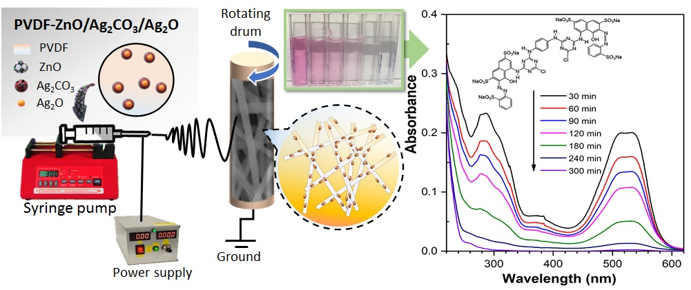
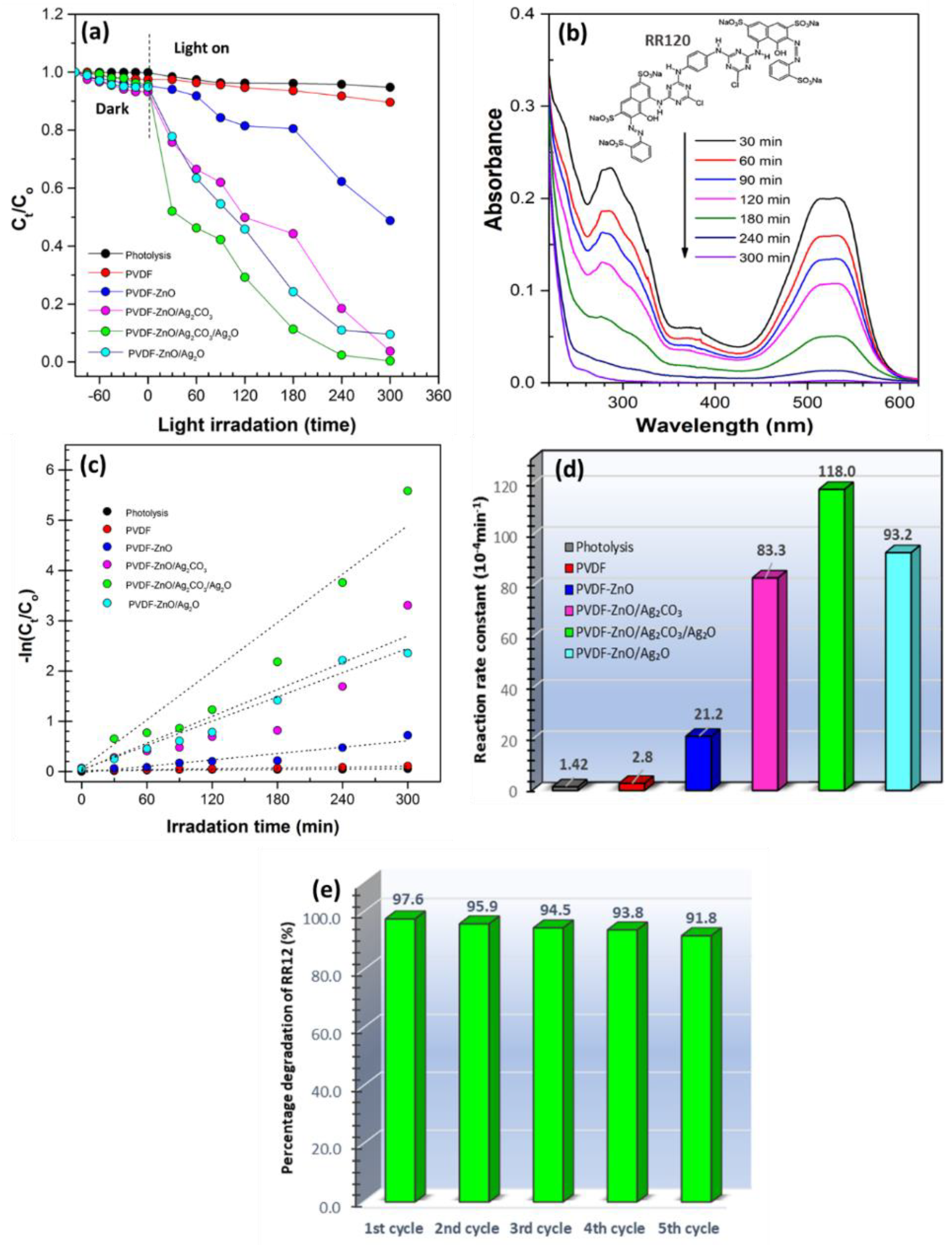
2.2. Evaluation of Photocatalytic Activity

Photocatalytic activities of the prepared electrospun nanofibers were tested out for the degradation of organic pollutant under UV light irradiation by using the reactive red 12 (RR120) as a model pollutant. The change in optical absorption spectra of RR120 by the electrospun nanofiber under UV light irradiation as a function of time is shown in Figure 8a. It was found that the adsorption of RR120 had increased, as the photocatalyst was incorporated into the PVDF nanofibers. After 90 min of adsorption, the PVDF-ZnO/Ag2CO3 showed the highest RR120 adsorption at 6.76%, compared to PVDF-ZnO, PVDF-ZnO/Ag2CO3/Ag2O, and PVDF-ZnO/Ag2O at 4.62%, 4.33%, and 5.19%, respectively. The difference in RR120 adsorption is due to the difference in their surface properties (e.g., surface area and surface roughness) [69,70]. Based on the analysis, BET surface area and surface roughness of PVDF embedded with ZnO heterojunctioned photocatalyst are higher compared to the pristine PVDF and PVDF-ZnO nanofiber. The higher BET surface area and surface roughness would contribute to higher percentage of adsorption, hence increasing the chances for UV to reach and come into contact with the photocatalyst through its highly porous interconnected nanofiber media. The photolysis of the RR120 solution without the addition of electrospun nanofiber was carried out as a controlled experiment. As shown in Figure 8a, there was a slight prominent change for the RR120 solution after UV light irradiation for 300 min, in which the RR120 can be categorized as having good photostability and potential resistance under the UV light irradiation [71]. The photocatalytic activity using pristine PVDF nanofiber without the presence of photocatalyst was also performed for comparison purposes. As portrayed in Figure 8a, the pristine PVDF nanofiber exhibited an approximately 10.43% adsorption of RR120 after 300 min of UV light irradiation.
After the addition of ZnO, the photodegradation of RR120 was found to have increased up to 28.14%. Meanwhile, in the impregnation of ZnO/Ag2CO3 heterojunctioned into the PVDF nanofiber, the photocatalytic activity of the samples increased, as compared to the PVDF-ZnO nanofiber. The highest photocatalytic activity was obtained by PVDF-ZnO/Ag2CO3/Ag2O with 99.62% degradation after 300 min of reaction, followed by PVDF-ZnO/Ag2O and PVDF-ZnO/Ag2CO3 of 96.34% and 90.49%, respectively. The lowest photocatalytic activity was obtained for PVDF-ZnO/Ag2O. This is possibly due to the smaller band gap possessed by the Ag2O. Hence, the potential recombination of electron-hole pair could exist, which would indirectly lower the production of hydroxyl radical, as well as photocatalytic reaction. The change in the absorption spectrum of RR120 with PVDF-ZnO/Ag2CO3/Ag2O electrospun at different time intervals is presented in Figure 8b. As the reaction time increased, all the peaks decreased gradually, and the spectrum scanning model distorted apparently after 300 min. The magnitude of the absorption peak at 533 nm slowly declined, indicating the reduction of RR120 concentration. According to Panakoulias et al. [72], the visible band at 533 nm owed to the RR120 nitro groups breakdown (discoloration of the solution) (Figure 8b inset), while it progressed with the cleavage of the aromatic ring at absorption bands 265 and 330 nm. The elimination of absorbance at 330 and 265 nm caused it to continue producing aliphatic intermediates that would be mineralized to carbon dioxide. A similar observation has also been made by Balachandran et al. [73], where a similar pattern of the absorption peak reduction without the appearance of new absorption peaks during the degradation process revealed the intermediates do not absorb at the analytical wavelengths of 285 and 533 nm.
The Langmuir-Hinshelwood model was extensively applied for the analysis of photocatalytic degradation kinetics of pollutant in aqueous phase, as follows [74]:
ln (Ct/C0) = −kt
where, C0 and Ct refer to the concentrations of pollutant (mgL−1) at the respective irradiation time 0 and t min, while k is the apparent rate (min−1). The pseudo-first-order kinetic model refers to the photocatalytic activity of RR120 in aqueous solution by the prepared electrospun nanofiber, in which Figure 8c shows the equal value of rate constant k to the corresponding slope of the fitting line. Figure 8d exhibits the reaction rate constant of all of the prepared nanofibers.
The pristine PVDF electrospun nanofiber showed that the relatively low reaction rate was obtained for nanofiber without photocatalyst. The main reason for the reduction of RR120 concentration is mainly due to the adsorption process. However, when ZnO, ZnO/Ag2CO3, ZnO/Ag2CO3/Ag2O, and ZnO/Ag2O were embedded in the PVDF electrospun nanofiber, a higher reduction of RR120 concentration was observed. This is because two processes were involved: The adsorption and photocatalysis processes. The photocatalyst provided the surface that was responsible for the photocatalysis process. Overall, PVDF nanofiber incorporated with the heterojunctioned ZnO composite photocatalyst significantly increased the photocatalytic activity. The PVDF-ZnO/Ag2CO3/Ag2O exhibited the highest reaction rate constant of 118 × 10−4 min−1, which was about 1.26, 1.42, and 5.57 times higher than those of PVDF-ZnO/Ag2O, PVDF-ZnO/Ag2CO3, and PVDF-ZnO, respectively.
The competency of the as-spun photocatalytic nanofibers is essentially accomplished through the synergetic combination of a highly porous structure and a high surface area generated by the nanofiber microstructure, which accurately aids in the adsorption migration-photodegradation process [75]. The RR120 is likely to be adsorbed by the PVDF nanofibers because of the lower hydrophobization took place via the PVDF-ZnO nanofiber while shifting to the photocatalyst nanoparticles, and finally degraded under the UV irradiation [47].
Figure 8e shows the recyclability test, demonstrating that the PVDF-ZnO/Ag2CO3/Ag2O nanofiber indicated a comparable degradation performance for the five consecutive cycles. It was suggested that the PVDF-ZnO/Ag2CO3/Ag2O was relatively stable after multiple cycles, even though there was a slight decline in the photodegradation rate for RR120. This proposes a robust physical interlocking of photocatalyst in the PVDF nanofiber matrix [76]. In fact, no leaching of photocatalyst was observed during the experiment. The remarkable recyclability of PVDF-ZnO/Ag2CO3/Ag2O electrospun nanofiber proved their potential for practical applications in a large scale.
Based on the above results, a proposed mechanism was discussed toward the development of the photocatalytic properties of the PVDF-ZnO/Ag2CO3/Ag2O composite nanofiber. In the present work, fibers with an average diameter of 645 ± 0.48 nm loaded with ZnO/Ag2CO3/Ag2O photocatalyst nanoparticles create groups of higher fiber diameter (Figure 2), hence offering a much higher specific surface area with a larger interaction of the dye and the inorganic filler, suggesting a faster degradation mechanism. However, due to the hydrophobic nature of PVDF polymer (Figure 4), the degradation of pink dye was only possible due to the interaction of the ZnO/Ag2CO3/Ag2O photocatalyst with the dye. In this sense, the enhanced photocatalytic degradation is primarily due to the synergetic combination of porous structure and higher surface area formed by the fiber microstructure, which competently allowed the adsorption migration-photodegradation process as aforementioned during degradation of RR120. In this way, the RR120 is possibly adsorbed by the polymer fibers, then migrated to the ZnO/Ag2CO3/Ag2O nanoparticles, and finally degraded by ZnO/Ag2CO3/Ag2O under UV radiation.
On the mechanism of ZnO/Ag2CO3/Ag2O surfaces, the heterojunctioned of Ag2CO3/Ag2O mixed phase were believed to exhibit cooperative effects between Ag2CO3, Ag2O, and ZnO. Under UV irradiation, the ZnO, Ag2CO3, and Ag2O absorbed the photon energy produced the excite electron in from VB to CB, leaving the positive holes at VB. Since the position of the Ag2CO3 CB is less negative than ZnO and Ag2O, the photogenerated electron produced by ZnO and Ag2O should be transferred to Ag2CO3, while the photogenerated positive holes were left in VB migrated to Ag2O. The positive holes accumulated in the surface of Ag2O were eventually trapped by surface hydroxyl groups (or H2O) to harvest OH∙ radicals. Dissolved oxygen molecules react to the electrons (e) at Ag2CO3 surfaces to produce superoxide anion radicals, while O2 yields the hydroperoxyl, HO2∙radicals, and directly generated hydroxyl radical OH. These super oxide radicals, O2 and OH, were very energetic radicals to phenyl or naphthyl rings of the aromatic compounds containing in RR120 [77,78]. Thus, the mechanism for the photocatalytic degradation of RR120 in the experiment was proposed as follows:
ZnO / Ag 2 CO 3 / Ag 2 O +   h v     e ( Ag 2 CO 3 ) +   h + ( Ag 2 O )
e +   O 2   O 2
h + +   OH OH
O 2 +   H 2 O   HO 2 + OH
HO 2 +   H 2 O     H 2 O 2 + OH
H 2 O 2 2 · OH  
OH + RR 120   CO 2 + H 2 O  
The overall separation and transfer of photogenerated electron-holes pairs in ZnO/Ag2CO3/Ag2O across the PVDF nanofiber and photodegradation of RR120 under UV light irradiation is schematically presented in Figure 9.

3. Materials and Methods

3.1. Material

The zinc acetate dihydrate (C4H6O4Zn·2H2O) supplied from GmbH company (Haan, Germany) was used as a zinc precursor. Silver nitrate (AgNO3) and sodium bicarbonate (NaHCO3) were purchased from Sigma Aldrich (St. Louis, MI, USA) and Bendosen (Bendosen, Norway), respectively. Polyvinylidene fluoride (PVDF, MW = 7400) and N, N-dimethylacetamide (DMAc) was produced from Merck (Kenilworth, NJ, USA), while acetone (>99.6% purity, HPLC grade) was obtained from QReC (Chonburi, Thailand), and the Reactive Red 120 (RR120) was purchased from Sigma Aldrich (St. Louis, MI, USA). All of the chemicals and reagents were analytical reagent grade and no purification step was performed.

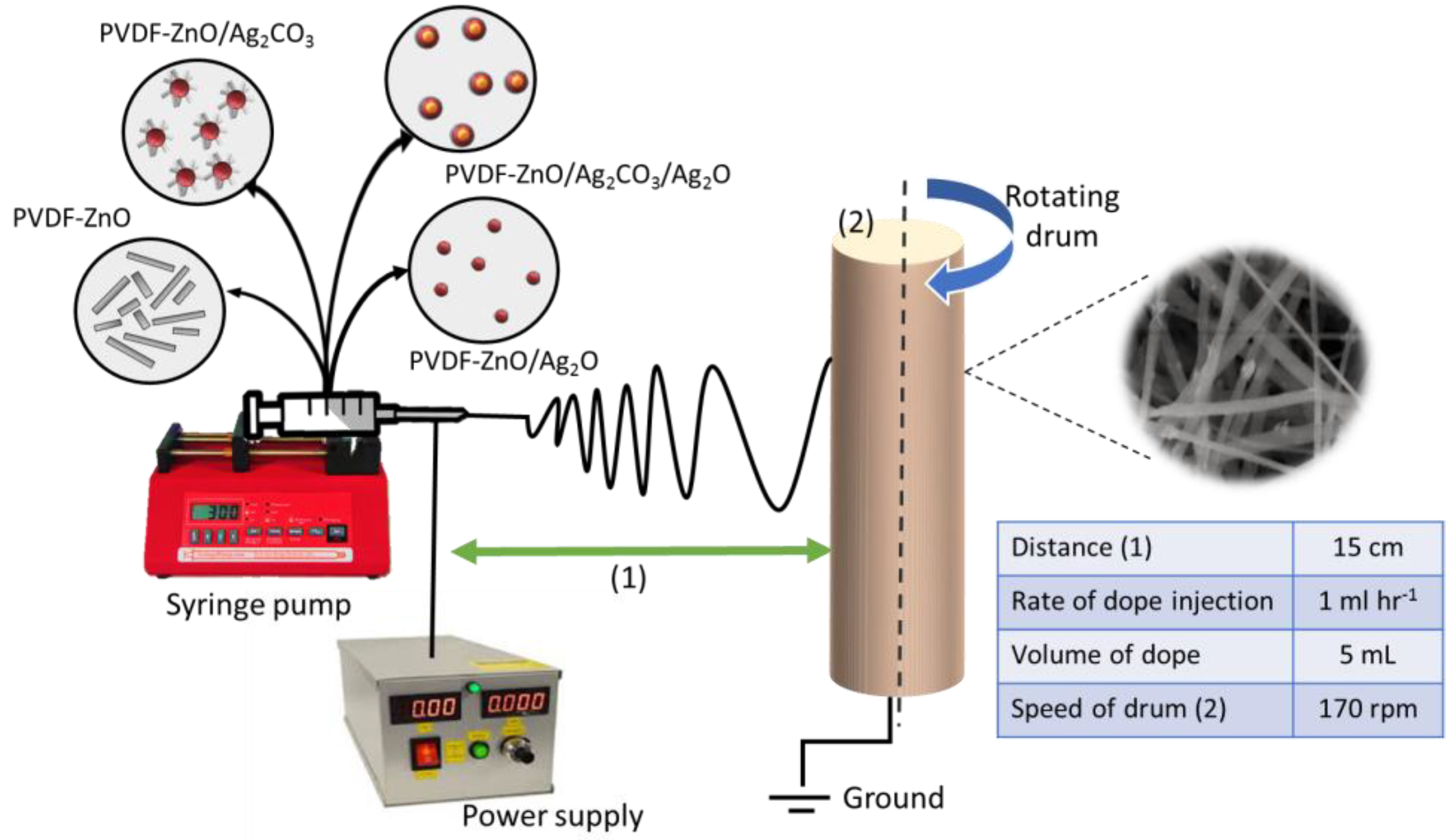
3.2. Preparation of the Electrospun Nanofiber

The photocatalyst was synthesized according to our previous study [24]. First, 1.95 g of PVDF pellets was added into 13 mL of DMAc solution prepared with acetone at the mass ratio of 2:3 and stirred at 60 °C until the polymer was dissolved. After that, 0.65 g of ZnO was added into the dope solution and stirred continuously at room temperature until a homogenous solution was obtained. The dope solution was then used in the fabrication of electrospun nanofiber via electrospinning, as shown in Figure 10. Seven milliliters of the dope solution was placed in a 10 mL syringe, equipped with a blunt metal needle. The electrospun was at a spinning rate of 1 mL/h, with a voltage of 8 kV applied between the spinneret and rotating drum placed 150 mm apart. Meanwhile, the collector of the rotating drum was set to 170 rpm. The flat sheet of the fabricated nanofibers was then allowed to dry at room temperature for the hydrolysis step before it was further characterized and tested. The same procedures were repeated for different photocatalysts of ZnO/Ag2CO3, ZnO/Ag2CO3/Ag2O, and ZnO/Ag2O. The resultant samples were denoted, as depicted in Table 2.

3.3. Characterization

The phase compositions of the prepared electrospun nanofiber derived from PVDF embedded with heterojunctioned ZnO were analyzed using the Rint 2200 Ultima-III X-ray Diffractometer (Rigaku, Corp., Tokyo, Japan). The morphological structure of the electrospun nanofibers was observed by scanning electron microscope (SEM, TM-1000, HITACHI, Tokyo, Japan) operated at 5 kV. The surface roughness of the electrospun nanofiber was further measured using the atomic force microscopy (AFM, PARK XE-100, Schaefer Technologie GmbH, Langen, Germany). The surface wettabilities of the electrospun nanofiber were determined by contact angle measurements with an optical contact angle machine (OCA 40 Micro, Dataphysics, Filderstadt, Germany). Nitrogen adsorption/desorption measurement was carried out at a low temperature (77.38 K) and a relative pressure range of P/P0 = 0.02 to 1 to determine the BET surface area and pore size distribution (using Barrett Joyner Halenda (BJH) equation). Prior to the measurement, the electrospun nanofibers were degassed at 373 K for 3 h in the degas port of the adsorption analyzer. Fourier transform infrared spectroscopy (FTIR: Spectrum 100, PerkinElmer, Waltham, MA, USA) was used to observe the presence of photocatalyst in the PVDF electrospun nanofiber matrix. The optical properties of the electrospun nanofibers were analyzed by UV–Vis-NIR spectrophotometer (UV-3600 Plus Shidmadzu, Japan) in the range of 200 to 800 nm. The collected spectra were converted into Kubelka-Munk function to measure the band gap of the prepared PVDF-ZnO/Ag2X electrospun nanofiber.

3.4. Photocatalytic Activity Measurement

The photocatalytic activity of the prepared electrospun nanofiber containing PVDF embedded with the heterojunctioned ZnO was performed under UV light irradiation using RR120 as a model pollutant. A 30 W lamp (312 nm) was used as a UV light source. The prepared electrospun nanofiber were cut into spherical shape (diameter of 8 cm, weight of 0.1 g) and immersed in 100 mL of RR120 solution. The photocatalytic experiment was first evaluated in the dark to observe the adsorption/desorption equilibrium of RR120 on the prepared nanofibers. During the photocatalytic tests, fixed amounts of the reacted solution were taken out at given time intervals. The final concentration of the RR120 solution was measured by collecting its absorbance at a wavelength of 533 nm with a UV–Vis spectrophotometer (Lambda 25, Perkin Elmer, Waltham, MA, USA). The degradation percentages of RR120 in the aqueous solution was calculated as follows: Degradation (%) = (C0Ct)/C0 100%; where C0 is the initial concentration at time t = 0, and Ct is the concentration time interval. The used electrospun nanofiber was collected and dried overnight at 60 °C in an oven. For the recyclability study, all of the electrospun nanofibers were reused under similar photocatalytic conditions for five cycles. The experiment was conducted at room temperature and in a neutral pH.

4. Conclusions

In summary, a series of PVDF electrospun nanofiber embedded with ZnO heterojunction photocatalysts with different Ag-based compounds were successfully fabricated via a facile electrospinning process. The higher dye removal efficiency of the composite electrospun nanofiber was mainly due to a novel synergistic effect of adsorption and photocatalytic degradation in the presence of heterojunctioned catalyst, which was ZnO/Ag2CO3, ZnO/Ag2CO3/Ag2O, and ZnO/Ag2O. The heterojunctioned catalyst embedded into the PVDF electrospun possessed lower hydrophobization and higher surface roughness, which facilitated the dye molecule adsorption adjacent to their photocatalytic surface sites. The embedding of ZnO/Ag2CO3/Ag2O into PVDF nanofiber led to a fast degradation of dye molecule among the electrospun nanocomposites under UV light irradiation, which was mainly attributed to the heterojunction between the ZnO and Ag2CO3/Ag2O mixed phase, narrowing the band gap. Hence, this effectively facilitated the charge transfer and suppressed the recombination of photogenerated electrons and holes for high photodegradation activity. Furthermore, the PVDF-ZnO/Ag2CO3/Ag2O electrospun nanofiber had maintained a relatively high photocatalytic activity after five cycles, which made them a promising candidate for a wide range of photocatalytic applications. However, to move toward commercialization, drawbacks of lacking nanoscale selectivity, mechanical weakness, and low wettability must be achieved.

Author Contributions

Conceptualization, W.N.W.S.; Formal Analysis, N.R., S.S.B.; Investigation, N.R., S.S.B.; Writing-Original Draft, N.R.; Writing-Review & Editing, W.N.W.S.; Supervision, W.N.W.S., F.A., Z.H.; Funding Acquisition, W.N.W.S.; Resources, A.F.I., K.N.

Funding

This research was funded by the Universiti Teknologi Malaysia under the Research University Grant (Grant No. Q.J130000.3551.05G76) and Ministry of Education under Malaysia Research University Network Grant (Grant No. R.J1300000.7851.4L863).

Acknowledgments

This work was financially supported by Universiti Teknologi Malaysia under the Research University Grant (Grant No. Q.J130000.3551.05G76) and Ministry of Education under Malaysia Research University Network Grant (Grant No. R.J1300000.7851.4L863) which are greatly acknowledged.

Conflicts of Interest

The authors declare no conflict of interest.

References

  1. Martínez-Huitle, C.A.; Brillas, E. Decontamination of wastewaters containing synthetic organic dyes by electrochemical methods: A general review. Appl. Catal. B Environ. 2009, 87, 105–145. [Google Scholar] [CrossRef]
  2. Ni, M.; Leung, M.K.; Leung, D.Y.; Sumathy, K. A review and recent developments in photocatalytic water-splitting using TiO2 for hydrogen production. Renew. Sustain. Energy Rev. 2007, 11, 401–425. [Google Scholar] [CrossRef]
  3. Moniz, S.J.; Shevlin, S.A.; Martin, D.J.; Guo, Z.-X.; Tang, J. Visible-light driven heterojunction photocatalysts for water splitting–a critical review. Energy Environ. Sci. 2015, 8, 731–759. [Google Scholar] [CrossRef]
  4. Johar, M.A.; Afzal, R.A.; Alazba, A.A.; Manzoor, U. Photocatalysis and Bandgap Engineering Using ZnO Nanocomposites. Adv. Mater. Sci. Eng. 2015, 15, 1–22. [Google Scholar] [CrossRef]
  5. Song, L.; Qiu, R.; Mo, Y.; Zhang, D.; Wei, H.; Xiong, Y. Photodegradation of phenol in a polymer-modified TiO2 semiconductor particulate system under the irradiation of visible light. Catal. Commun. 2007, 9, 429–433. [Google Scholar] [CrossRef]
  6. Yan, Y.; Guan, H.; Liu, S.; Jiang, R. Ag3PO4/Fe2O3 composite photocatalysts with an n–n heterojunction semiconductor structure under visible-light irradiation. Ceram. Int. 2014, 40, 9095–9100. [Google Scholar] [CrossRef]
  7. Guan, M.; Xiao, C.; Zhang, J.; Fan, S.; An, R.; Cheng, Q.; Xie, J.; Zhou, M.; Ye, B.; Xie, Y. Vacancy Associates Promoting Solar-Driven Photocatalytic Activity of Ultrathin Bismuth Oxychloride Nanosheets. J. Am. Chem. Soc. 2013, 135, 10411–10417. [Google Scholar] [CrossRef]
  8. Chen, X.; Wu, Z.; Liu, D.; Gao, Z. Preparation of ZnO photocatalyst for the efficient and rapid photocatalytic degradation of azo dyes. Nanoscale Res. Lett. 2017, 12, 143. [Google Scholar] [CrossRef]
  9. Lee, K.M.; Lai, C.W.; Ngai, K.S.; Juan, J.C. Recent developments of zinc oxide based photocatalyst in water treatment technology: A review. Water Res. 2016, 88, 428–448. [Google Scholar] [CrossRef]
  10. Hosseini, S.M.; Sarsari, I.A.; Kameli, P.; Salamati, H. Effect of Ag doping on structural, optical, and photocatalytic properties of ZnO nanoparticles. J. Alloy. Compd. 2015, 640, 408–415. [Google Scholar] [CrossRef] [Green Version]
  11. Feng, N.; Wang, Q.; Zheng, A.; Zhang, Z.; Fan, J.; Liu, S.B.; Amoureux, J.P.; Deng, F. Understanding the High Photocatalytic Activity of (B, Ag)-Codoped TiO2 under Solar-Light Irradiation with XPS, Solid-State NMR, and DFT Calculations. J. Am. Chem. Soc. 2013, 135, 1607–1616. [Google Scholar] [CrossRef] [PubMed]
  12. Yıldırım, Ö.A.; Unalan, H.E.; Durucan, C. Highly Efficient Room Temperature Synthesis of Silver-Doped Zinc Oxide (ZnO:Ag) Nanoparticles: Structural, Optical, and Photocatalytic Properties. J. Am. Ceram. Soc. 2013, 96, 766–773. [Google Scholar] [CrossRef]
  13. Mohamed, M.A.; Salleh, W.N.; Jaafar, J.; Rosmi, M.S.; Hir, Z.A.; Mutalib, M.A.; Ismail, A.F.; Tanemura, M. Carbon as amorphous shell and interstitial dopant in mesoporous rutile TiO2: Bio-template assisted sol-gel synthesis and photocatalytic activity. Appl. Surf. Sci. 2017, 393, 46–59. [Google Scholar] [CrossRef]
  14. Mohamed, M.A.; Salleh, W.N.W.; Jaafar, J.; Ismail, A.F.; Abd Mutalib, M.; Jamil, S.M. Incorporation of N-doped TiO2 nanorods in regenerated cellulose thin films fabricated from recycled newspaper as a green portable photocatalyst. Carbohydr. Polym. 2015, 133, 429–437. [Google Scholar] [CrossRef] [PubMed]
  15. Rengifo-Herrera, J.A.; Pulgarin, C. Photocatalytic activity of N, S co-doped and N-doped commercial anatase TiO2 powders towards phenol oxidation and E. coli inactivation under simulated solar light irradiation. Sol. Energy 2010, 84, 37–43. [Google Scholar] [CrossRef]
  16. Yu, S.; Yun, H.J.; Kim, Y.H.; Yi, J. Carbon-doped TiO2 nanoparticles wrapped with nanographene as a high performance photocatalyst for phenol degradation under visible light irradiation. Appl. Catal. B Environ. 2014, 144, 893–899. [Google Scholar] [CrossRef]
  17. Zhang, X.; Qin, J.; Hao, R.; Wang, L.; Shen, X.; Yu, R.; Limpanart, S.; Ma, M.; Liu, R. Carbon-Doped ZnO Nanostructures: Facile Synthesis and Visible Light Photocatalytic Applications. J. Phys. Chem. C 2015, 119, 20544–20554. [Google Scholar] [CrossRef]
  18. Lin, L.; Yang, Y.; Men, L.; Wang, X.; He, D.; Chai, Y.; Zhao, B.; Ghoshroy, S.; Tang, Q. A highly efficient TiO2@ZnO n–p–n heterojunction nanorod photocatalyst. Nanoscale 2013, 5, 588–593. [Google Scholar] [CrossRef]
  19. Zhang, Z.; Shao, C.; Li, X.; Zhang, L.; Xue, H.; Wang, C.; Liu, Y. Electrospun Nanofibers of ZnO-SnO2 Heterojunction with High Photocatalytic Activity. J. Phys. Chem. C 2010, 114, 7920–7925. [Google Scholar] [CrossRef]
  20. Chong, M.N.; Jin, B.; Chow, C.W.; Saint, C. Recent developments in photocatalytic water treatment technology: A review. Water Res. 2010, 44, 2997–3027. [Google Scholar] [CrossRef]
  21. Mohamed, M.A.; Jaafar, J.; Zain, M.; Minggu, L.J.; Kassim, M.B.; Salehmin, M.N.I.; Rosmi, M.S.; Salleh, W.; Othman, M.H.D. Concurrent growth, structural and photocatalytic properties of hybridized C, N co-doped TiO2 mixed phase over g-C3N4 nanostructured. Scr. Mater. 2018, 142, 143–147. [Google Scholar] [CrossRef]
  22. Pirhashemi, M.; Habibi-Yangjeh, A. Ternary ZnO/AgBr/Ag2CrO4 nanocomposites with tandem n–n heterojunctions as novel visible-light-driven photocatalysts with excellent activity. Ceram. Int. 2015, 41, 14383–14393. [Google Scholar] [CrossRef]
  23. Kiantazh, F.; Habibi-Yangjeh, A. Ag3VO4-ZnO nanocomposites with an n–n heterojunction as novel visible-light-driven photocatalysts with highly enhanced activity. Mater. Sci. Semicond. Process. 2015, 39, 671–679. [Google Scholar] [CrossRef]
  24. Rosman, N.; Salleh, W.N.; Ismail, A.F.; Jaafar, J.; Harun, Z.; Aziz, F.; Mohamed, M.A.; Ohtani, B.; Takashima, M. Photocatalytic degradation of phenol over visible light active ZnO/Ag2CO3/Ag2O nanocomposites heterojunction. J. Photochem. Photobiol. A Chem. 2018, 364, 602–612. [Google Scholar] [CrossRef]
  25. Ardoña, H.A.M.; Paredes, F.U.; Arellano, I.H.J.; Arco, S.D. Electrospun PET supported-ionic liquid-stabilized CdS catalyst for the photodegradation of Rhodamine B under visible light. Mater. Lett. 2013, 91, 96–99. [Google Scholar] [CrossRef]
  26. Rosman, N.; Salleh, W.; Mohamed, M.A.; Jaafar, J.; Ismail, A.; Harun, Z. Hybrid membrane filtration-advanced oxidation processes for removal of pharmaceutical residue. J. Colloid Interface Sci. 2018, 532, 236–260. [Google Scholar] [CrossRef] [PubMed]
  27. Lv, Y.; Zhang, C.; He, A.; Yang, S.J.; Wu, G.P.; Darling, S.B.; Xu, Z.K. Photocatalytic Nanofiltration Membranes with Self-Cleaning Property for Wastewater Treatment. Adv. Funct. Mater. 2017, 27, 1700251. [Google Scholar] [CrossRef]
  28. Lee, A.; Libera, J.A.; Waldman, R.Z.; Ahmed, A.; Avila, J.R.; Elam, J.W.; Darling, S.B. Conformal Nitrogen-Doped TiO2 Photocatalytic Coatings for Sunlight-Activated Membranes. Adv. Sustain. Syst. 2017, 1, 1600041. [Google Scholar] [CrossRef]
  29. Drioli, E.; Giorno, L. Comprehensive Membrane Science and Engineering; Newnes: Oxford, UK, 2010; Volume 1. [Google Scholar]
  30. Rao, K.V.S.; Subrahmanyam, M.; Boule, P. Immobilized TiO2 photocatalyst during long-term use: Decrease of its activity. Appl. Catal. B Environ. 2004, 49, 239–249. [Google Scholar] [CrossRef]
  31. Hoogesteijn von Reitzenstein, N.; Bi, X.; Yang, Y.; Hristovski, K.; Westerhoff, P. Morphology, structure, and properties of metal oxide/polymer nanocomposite electrospun mats. J. Appl. Polym. Sci. 2016, 133. [Google Scholar] [CrossRef]
  32. Lee, S.S.; Bai, H.; Liu, Z.; Sun, D.D. Optimization and an insightful properties—activity study of electrospun TiO2/CuO composite nanofibers for efficient photocatalytic H2 generation. Appl. Catal. B Environ. 2013, 140, 68–81. [Google Scholar] [CrossRef]
  33. Yang, D.; Liu, H.; Zheng, Z.; Yuan, Y.; Zhao, J.-c.; Waclawik, E.R.; Ke, X.; Zhu, H. An efficient photocatalyst structure: TiO2 (B) nanofibers with a shell of anatase nanocrystals. J. Am. Chem. Soc. 2009, 131, 17885–17893. [Google Scholar] [CrossRef] [PubMed]
  34. Wang, X.; Yu, J.; Sun, G.; Ding, B. Electrospun nanofibrous materials: A versatile medium for effective oil/water separation. Mater. Today 2016, 19, 403–414. [Google Scholar] [CrossRef]
  35. Ghaly, M.Y.; Ali, M.E.M.; Österlund, L.; Khattab, I.A.; Badawy, M.I.; Farah, J.Y.; Zaher, F.M.; Al-Maghrabi, M.N. ZnO/spiral-shaped glass for solar photocatalytic oxidation of Reactive Red 120. Arab. J. Chem. 2017, 10, S3501–S3507. [Google Scholar] [CrossRef] [Green Version]
  36. Lin, L.; Jiang, W.; Bechelany, M.; Nasr, M.; Jarvis, J.; Schaub, T.; Sapkota, R.R.; Miele, P.; Wang, H.; Xu, P. Adsorption and photocatalytic oxidation of ibuprofen using nanocomposites of TiO2 nanofibers combined with BN nanosheets: Degradation products and mechanisms. Chemosphere 2019, 220, 921–929. [Google Scholar] [CrossRef]
  37. Karim, S.A.; Mohamed, A.; Abdel-Mottaleb, M.; Osman, T.; Khattab, A. Visible light photocatalytic activity of PAN-CNTs/ZnO-NH2 electrospun nanofibers. J. Alloy. Compd. 2019, 772, 650–655. [Google Scholar] [CrossRef]
  38. Abdel-Mottaleb, M.; Khalil, A.; Karim, S.; Osman, T.; Khattab, A. High performance of PAN/GO-ZnO composite nanofibers for photocatalytic degradation under visible irradiation. J. Mech. Behav. Biomed. 2019, 96, 118–124. [Google Scholar] [CrossRef]
  39. Mao, Z.; Xie, R.; Fu, D.; Zhang, L.; Xu, H.; Zhong, Y.; Sui, X. PAN supported Ag-AgBr@Bi20TiO32 electrospun fiber mats with efficient visible light photocatalytic activity and antibacterial capability. Sep. Purif. Technol. 2017, 176, 277–286. [Google Scholar] [CrossRef]
  40. Huang, Z.-M.; Zhang, Y.-Z.; Kotaki, M.; Ramakrishna, S. A review on polymer nanofibers by electrospinning and their applications in nanocomposites. Compos. Sci. Technol. 2003, 63, 2223–2253. [Google Scholar] [CrossRef]
  41. Li, D.; Xia, Y. Direct fabrication of composite and ceramic hollow nanofibers by electrospinning. Nnao Lett. 2006, 4. [Google Scholar] [CrossRef]
  42. Patel, A.C.; Li, S.; Wang, C.; Zhang, W.; Wei, Y. Electrospinning of Porous Silica Nanofibers Containing Silver Nanoparticles for Catalytic Applications. Chem. Mater. 2007, 19, 1231–1238. [Google Scholar] [CrossRef]
  43. Wang, G.; Pan, C.; Wang, L.; Dong, Q.; Yu, C.; Zhao, Z.; Qiu, J. Activated carbon nanofiber webs made by electrospinning for capacitive deionization. Electrochim. Acta 2012, 69, 65–70. [Google Scholar] [CrossRef]
  44. Azad, A.-M. Fabrication of transparent alumina (Al2O3) nanofibers by electrospinning. Mater. Sci. Eng. A 2006, 435–436, 468–473. [Google Scholar] [CrossRef]
  45. Reneker, D.H.; Yarin, A.L. Electrospinning jets and polymer nanofibers. Polymer 2008, 49, 2387–2425. [Google Scholar] [CrossRef] [Green Version]
  46. Teng, H. Overview of the Development of the Fluoropolymer Industry. Appl. Sci. 2012, 2, 496–512. [Google Scholar] [CrossRef]
  47. He, T.; Zhou, Z.; Xu, W.; Ren, F.; Ma, H.; Wang, J. Preparation and photocatalysis of TiO2–fluoropolymer electrospun fiber nanocomposites. Polymer 2009, 50, 3031–3036. [Google Scholar] [CrossRef]
  48. Ning, J.; Zhang, X.; Yang, H.; Xu, Z.L.; Wei, Y.M. Preparation of Porous PVDF Nanofiber Coated with Ag NPs for Photocatalysis Application. Fibers Polym. 2016, 17, 21–29. [Google Scholar] [CrossRef]
  49. Richard, M.; Nthumbi, J.C.N. Electrospun and functionalized PVDF/PAN nanocatalyst-loaded composite for dechlorination and photodegradation of pesticides in contaminated water. Environ. Sci. Pollut. Res. 2016, 23, 20214–20231. [Google Scholar] [CrossRef]
  50. Brahma, S.; Rao, K.J.; Shivashankar, S. Rapid growth of nanotubes and nanorods of würtzite ZnO through microwave-irradiation of a metalorganic complex of zinc and a surfactant in solution. Bull. Mater. Sci. 2010, 33, 89–95. [Google Scholar] [CrossRef]
  51. Liu, S.; Wang, L.; Dai, G.; Hou, Q. Fabrication of Ag2CO3/SrCO3 Rods with Highly Efficient Visible-light Photocatalytic Activity. Rare Met. Mater. Eng. 2017, 46, 312–316. [Google Scholar] [CrossRef]
  52. Wang, X.; Li, S.; Yu, H.; Yu, J.; Liu, S. Ag2O as a New Visible-Light Photocatalyst: Self-Stability and High Photocatalytic Activity. Chem. A Eur. J. 2011, 17, 7777–7780. [Google Scholar] [CrossRef] [PubMed]
  53. Yu, C.; Li, G.; Kumar, S.; Yang, K.; Jin, R. Phase Transformation Synthesis of Novel Ag2O/Ag2CO3 Heterostructures with High Visible Light Efficiency in Photocatalytic Degradation of Pollutants. Adv. Mater. 2014, 26, 892–898. [Google Scholar] [CrossRef] [PubMed]
  54. Drew, C.; Wang, X.; Samuelson, L.A.; Kumar, J. The effect of viscosity and filler on electrospun fiber morphology. J. Macromol. Sci. Part A 2003, 40, 1415–1422. [Google Scholar] [CrossRef]
  55. Li, Z.; Wang, C. Effects of working parameters on electrospinning. In One-Dimensional Nanostructures; Springer: Berlin, Germany, 2013; pp. 15–28. [Google Scholar]
  56. Wang, X.; Ding, B.; Yu, J.; Wang, M. Engineering biomimetic superhydrophobic surfaces of electrospun nanomaterials. Nano Today 2011, 6, 510–530. [Google Scholar] [CrossRef]
  57. Ashraf, M.; Campagne, C.; Perwuelz, A.; Champagne, P.; Leriche, A.; Courtois, C. Development of superhydrophilic and superhydrophobic polyester fabric by growing zinc oxide nanorods. J. Colloid Interface Sci. 2013, 394, 545–553. [Google Scholar] [CrossRef]
  58. Thommes, M.; Kaneko, K.; Neimark, A.V.; Olivier, J.P.; Rodriguez-Reinoso, F.; Rouquerol, J.; Sing, K.S. Physisorption of gases, with special reference to the evaluation of surface area and pore size distribution (IUPAC Technical Report). Pure Appl. Chem. 2015, 87, 1051–1069. [Google Scholar] [CrossRef] [Green Version]
  59. ALOthman, Z. A review: Fundamental aspects of silicate mesoporous materials. Materials 2012, 5, 2874–2902. [Google Scholar] [CrossRef]
  60. Chen, S.; Tao, S.; Tang, D.; Xu, H.; Li, S.; Zhao, J.; Jiang, Q.; Yang, H. Pore structure characterization of different rank coals using N2 and CO2 adsorption and its effect on CH4 adsorption capacity: A case in Panguan syncline, Western Guizhou, china. Energy Fuels 2017, 31, 6034–6044. [Google Scholar] [CrossRef]
  61. Betz, N.; Le Moel, A.; Balanzat, E.; Ramillon, J.; Lamotte, J.; Gallas, J.; Jaskierowicz, G. A FTIR study of PVDF irradiated by means of swift heavy ions. J. Polym. Sci. Part B Polym. Phys. 1994, 32, 1493–1502. [Google Scholar] [CrossRef]
  62. Devi, P.I.; Ramachandran, K. Dielectric studies on hybridised PVDF–ZnO nanocomposites. J. Exp. Nanosci. 2011, 6, 281–293. [Google Scholar] [CrossRef]
  63. Li, C.; Xin, Q.; Guo, X.-X. Surface oxygen species and their reactivities in the mild oxidation of ethylene on cerium oxide studied by FT-IR spectroscopy. Catal. Lett. 1992, 12, 297–305. [Google Scholar] [CrossRef]
  64. Kadam, A.; Dhabbe, R.; Gophane, A.; Sathe, T.; Garadkar, K. Template free synthesis of ZnO/Ag2O nanocomposites as a highly efficient visible active photocatalyst for detoxification of methyl orange. J. Photochem. Photobiol. B Biol. 2016, 154, 24–33. [Google Scholar] [CrossRef] [PubMed]
  65. Lamba, R.; Umar, A.; Mehta, S.; Kansal, S.K. Enhanced visible light driven photocatalytic application of Ag2O decorated ZnO nanorods heterostructures. Sep. Purif. Technol. 2017, 183, 341–349. [Google Scholar] [CrossRef]
  66. Yu, C.; Wei, L.; Chen, J.; Xie, Y.; Zhou, W.; Fan, Q. Enhancing the photocatalytic performance of commercial TiO2 crystals by coupling with trace narrow-band-gap Ag2CO3. Ind. Eng. Chem. Res. 2014, 53, 5759–5766. [Google Scholar] [CrossRef]
  67. Kočí, K.; Reli, M.; Troppová, I.; Šihor, M.; Kupková, J.; Kustrowski, P.; Praus, P. Photocatalytic decomposition of N2O over TiO2/g-C3N4 photocatalysts heterojunction. Appl. Surf. Sci. 2017, 396, 1685–1695. [Google Scholar] [CrossRef]
  68. Xu, C.; Liu, Y.; Huang, B.; Li, H.; Qin, X.; Zhang, X.; Dai, Y. Preparation, characterization, and photocatalytic properties of silver carbonate. Appl. Surf. Sci. 2011, 257, 8732–8736. [Google Scholar] [CrossRef]
  69. Almasian, A.; Chizari Fard, G.; Parvinzadeh Gashti, M.; Mirjalili, M.; Mokhtari Shourijeh, Z. Surface modification of electrospun PAN nanofibers by amine compounds for adsorption of anionic dyes. Desalin. Water Treat. 2016, 57, 10333–10348. [Google Scholar] [CrossRef]
  70. Makaremi, M.; De Silva, R.T.; Pasbakhsh, P. Electrospun nanofibrous membranes of polyacrylonitrile/halloysite with superior water filtration ability. J. Phys. Chem. C 2015, 119, 7949–7958. [Google Scholar] [CrossRef]
  71. Suwannaruang, T.; Rivera, K.; Neramittagapong, A.; Wantala, K. Effects of hydrothermal temperature and time on uncalcined TiO2 synthesis for reactive red 120 photocatalytic degradation. Surf. Coat. Technol. 2015, 271, 192–200. [Google Scholar] [CrossRef]
  72. Panakoulias, T.; Kalatzis, P.; Kalderis, D.; Katsaounis, A. Electrochemical degradation of Reactive Red 120 using DSA and BDD anodes. J. Appl. Electrochem. 2010, 40, 1759–1765. [Google Scholar] [CrossRef]
  73. Balachandran, S.; Selvam, K.; Babu, B.; Swaminathan, M. The simple hydrothermal synthesis of Ag–ZnO–SnO2 nanochain and its multiple applications. Dalton Trans. 2013, 42, 16365–16374. [Google Scholar] [CrossRef] [PubMed]
  74. Konstantinou, I.K.; Albanis, T.A. TiO2-assisted photocatalytic degradation of azo dyes in aqueous solution: Kinetic and mechanistic investigations: A review. Appl. Catal. B Environ. 2004, 49, 1–14. [Google Scholar] [CrossRef]
  75. Cossich, E.; Bergamasco, R.; de Amorim, M.P.; Martins, P.; Marques, J.; Tavares, C.J.; Lanceros-Méndez, S.; Sencadas, V. Development of electrospun photocatalytic TiO2-polyamide-12 nanocomposites. Mater. Chem. Phys. 2015, 164, 91–97. [Google Scholar] [CrossRef]
  76. Dilpazir, S.; Usman, M.; Rasul, S.; Arshad, S. A simple UV-ozone surface treatment to enhance photocatalytic performance of TiO2 loaded polymer nanofiber membranes. RSC Adv. 2016, 6, 14751–14755. [Google Scholar] [CrossRef]
  77. Mohamed, M.A.; Zain, M.F.; Minggu, L.J.; Kassim, M.B.; Amin, N.A.; Salleh, W.N.; Salehmin, M.N.; Nasir, M.F.; Hir, Z.A. Constructing bio-templated 3D porous microtubular C-doped g-C3N4 with tunable band structure and enhanced charge carrier separation. Appl. Catal. B Environ. 2018, 236, 265–279. [Google Scholar] [CrossRef]
  78. Paul, J.; Rawat, K.P.; Sarma, K.S.; Sabharwal, S. Decoloration and degradation of Reactive Red-120 dye by electron beam irradiation in aqueous solution. Appl. Radiat. Isot. 2011, 69, 982–987. [Google Scholar] [CrossRef] [PubMed]
Figure 1. X-ray diffraction (XRD) spectra of (a) P0: PVDF; (b) P1: PVDF-ZnO, (c) P2: PVDF-ZnO/Ag2CO3; (d) P3: PVDF-ZnO/Ag2CO3/Ag2O; (e) P4: PVDF-ZnO/Ag2O; and (f) ZnO/Ag2CO3/Ag2O photocatalyst.
Catalysts 09 00565 g001
Figure 2. SEM images and the corresponding histograms of the electrospun nanofiber diameter distribution (a) P0: PVDF; (b) P1: PVDF-ZnO, (c) P2: PVDF-ZnO/Ag2CO3; (d) P3: PVDF-ZnO/Ag2CO3/Ag2O; (e) P4: PVDF-ZnO/Ag2O.
Catalysts 09 00565 g002
Figure 3. TEM images of PVDF/ZnO/Ag2CO3/Ag2O electrospun nanofiber; inset SAED pattern.
Catalysts 09 00565 g003
Figure 4. (1) Water contact angle images and (2) 3D AFM images of the prepared electrospun nanofibers ((a) P0: PVDF; (b) P1: PVDF-ZnO, (c) P2: PVDF-ZnO/Ag2CO3; (d) P3: PVDF-ZnO/Ag2CO3/Ag2O; (e) P4: PVDF-ZnO/Ag2O).
Catalysts 09 00565 g004
Figure 5. Nitrogen adsorption-desorption isotherms and the corresponding BJH pore-size distribution curves (insets) of the electrospun nanofibers (a) P0: PVDF; (b) P1: PVDF-ZnO, (c) P2: PVDF-ZnO/Ag2CO3; (d) P3: PVDF-ZnO/Ag2CO3/Ag2O; (e) P4: PVDF-ZnO/Ag2O.
Catalysts 09 00565 g005
Figure 6. Fourier transform infrared (FTIR) spectra of: (a) P0: PVDF; (b) P1: PVDF-ZnO, (c) P2: PVDF-ZnO/Ag2CO3; (d) P3: PVDF-ZnO/Ag2CO3/Ag2O; (e) P4: PVDF-ZnO/Ag2O.
Catalysts 09 00565 g006
Figure 7. (a) Absorbance spectra, (b) band gap determination by drawing the line at (αhυ)2 of the electrospun nanofibers.
Catalysts 09 00565 g007
Figure 8. (a) Degradation rates of RR120 solutions under UV light irradiation, (b) absorption spectra of RR120 with increasing irradiation time over P3 sample, (c) kinetics of the disappearance of RR120, (d) reaction rate constant of all samples, and (e) recyclability of the P3 sample for degradation of RR120 under UV light irradiation for several cycles.
Catalysts 09 00565 g008
Figure 9. Schematic diagram of the band edge alignment of the ZnO/Ag2CO3/Ag2O system along with the proposed mechanism of charge transfer.
Catalysts 09 00565 g009
Figure 10. Schematic diagram of the electrospinning process.
Catalysts 09 00565 g010
Table 1. The surface area and pore properties of the electrospun nanofibers.
SamplesBET Surface Area (m2g−1)Average Pore Size (nm)Pore Volume (×10−2 cm3g−1)
P03.7523.972.94
P14.1222.472.31
P26.6113.862.29
P36.5011.261.83
P46.2218.912.80
Table 2. Fabricated electrospun nanofiber.
Electrospun NanofiberSample
PVDFP0
PVDF-ZnOP1
PVDF-ZnO/Ag2CO3P2
PVDF-ZnO/Ag2CO3/Ag2OP3
PVDF-ZnO/Ag2OP4

