Review on the Evolution of Darrieus Vertical Axis Wind Turbine: Large Wind Turbines
by
 , , , and
Palanisamy Mohan Kumar
1,* ,
,
Krishnamoorthi Sivalingam
2,
Teik-Cheng Lim
2,
Seeram Ramakrishna
1 and
and
He Wei
3 1
Centre for Nanofibers and Nanotechnology, Department of Mechanical Engineering, National University of Singapore, Engineering Drive 3, Singapore 117587, Singapore
2
School of Science and Technology, Singapore University of Social Sciences, 463 Clementi Rd, Singapore 59949, Singapore
3
Singapore Institute of Manufacturing Technology, Surface Technology group, A*STAR, Fusionopolis way 2, Innovis, Singapore 138634, Singapore
*
Author to whom correspondence should be addressed.
Clean Technol. 2019, 1(1), 205-223; https://doi.org/10.3390/cleantechnol1010014
Submission received: 24 June 2019
/
Revised: 27 July 2019
/
Accepted: 29 July 2019
/
Published: 7 August 2019
(This article belongs to the Special Issue Cleaner Production Technologies)
Abstract
:The objective of the current review is to present the development of a large vertical axis wind turbine (VAWT) since its naissance to its current applications. The turbines are critically reviewed in terms of performance, blade configuration, tower design, and mode of failure. The early VAWTs mostly failed due to metal fatigue since the composites were not developed. Revisiting those configurations could yield insight into the future development of VAWT. The challenges faced by horizontal axis wind turbine (HAWT), especially in the megawatt capacity, renewed interest in large scale VAWT. VAWT provides a solution for some of the immediate challenges faced by HAWT in the offshore environment in terms of reliability, maintenance, and cost. The current rate of research and development on VAWT could lead to potential and economical alternatives for HAWT. The current summary on VAWT is envisioned to be an information hub about the growth of the Darrieus turbine from the kW capacity to megawatt scale.
Keywords:
vertical axis wind turbine (VAWT); Darrieus; megawatt; blade; failure; diameter; swept area; height; rated wind speed; crashed1. Introduction
Th exponential growth in energy demand along with fossil fuel depletion and global warming has created an avenue for the development of renewable energies. The clean energy technologies are widely accepted by countries worldwide to cater to the energy demand arising from the rapid growth of the human population. Wind power has become the key and reliable renewable energy source with a total installed capacity of 587 GW as of 2018 [1]. Several developing countries such as India and China have made significant efforts in adapting wind energy. Denmark, leading the wind industry, is the first country to be entirely powered by wind energy. By November 2013, Denmark even exported surplus power to neighbouring countries. Though the wind industry has witnessed rapid growth from 1996–2012, the history of the windmill dates back to the 7th century. Windmills in Persia (Iran) date back to 200 BC, with six to twelve sails made of cloths. These VAWTs are mainly used to pump water and to grind grains. Later in the 18th century, the first VAWT to generate electricity was created by James Blyoth, though the HAWT of Dutch windmill designs did exist in that period. It was in 1900, Finnish engineer Savonius created S-shaped blades called the Savonius turbine, which operates by the drag force. Despite its low efficiency and maximum rotational speed limited by wind speed, these turbines find its applications in mechanical pumps. Recent research on the Savonius turbine to avert the wind load [2] has opened up new areas of application. Innovative turbines are continuing to emerge to address the shortcomings of the original Darrieus design [3,4]. Tailored airfoils are developed for the Darrieus rotor to enhance self-starting capability [5,6,7,8]. Various mathematical models [3,7] are developed to assess the rotor performance. Computational simulation is extensively used to optimise the Darrieus turbine and serves as an alternative for costly prototyping [9]. The evolution of small VAWTs with the capacity of less than 50 kW are reviewed by the author in previous work [10]. This review has been categorised based on the timeline of development. The turbines are examined on their configuration, type of support, specifications, the reason for failure, and current status. The current study is a knowledge hub on past projects that yields valuable information on the failure to develop efficient and cost-effective VAWTs. Though the paper aims to cover most of the turbines that were developed in the past and current ongoing projects, there may be missing projects of which the author is unaware.
2. The Invention of the Darrieus Turbine
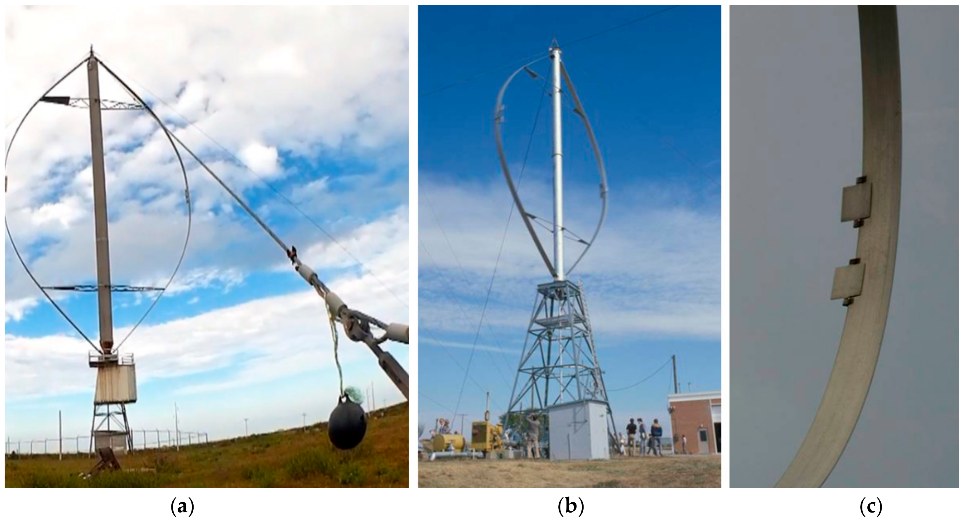
Before the invention of the Darrieus turbine, the drag-based Savonius turbines are employed as a source of mechanical power rather than electricity generation. With the need for electric power, efficient and high-speed machines are in demand. Hence, lift-based machines are proposed as an alternative to drag machines. The French aeronautical engineer Georges Jean Marie Darrieus patented Darrieus type wind turbines in the year 1931 [11]. The design has a vertical shaft supporting two airfoil blades, each in the shape of a bow, with the ends of each blade attached to the top and bottom of the shaft. The movement of these blades against the direction of the wind generates an aerodynamic force that acts on the shaft, causing the rotor to rotate. George Darrieus optimised vital parameters on his VAWT and installed several experimental wind turbines for his employer, Compagnie Electromécanique (CEM) in Bourget, outside Paris. The patented design is a phi configuration, three-bladed, as shown in Figure 1c. Around 1966, Raj Rangi and South from Canada National Research Council (CNRC) reintroduced Darrieus wind turbines suitable for power generation. The first Darrieus type VAWTs were developed in Canada by Raj Rangi and Peter South and were installed on the rooftop of the NRC [12] as shown in Figure 1a. Later in the year 1973, due to the oil crisis, countries were in search of an alternative source of power generation other than fossil fuels. Raj and South further researched on these turbines, while the manufacturing was contracted to Dominion Aluminium Fabrication Ltd. (DAF) [13]. One of the first machines manufactured by DAF was delivered to the Defence Research Establishment in Ottawa and was set up in the Arctic, as shown in Figure 1b. CNRC pioneered the research on Darrieus turbines for a decade. Later in 1970, Sandia National Laboratories (SNL) in the US adopted the design of the Darrieus turbine and led to further investigation on various configurations. Thereafter, the size of VAWT continued to grow to reach 3.8 megawatt as of 2019.
3. Large Vertical Axis Wind Turbines
3.1. DAF Indal
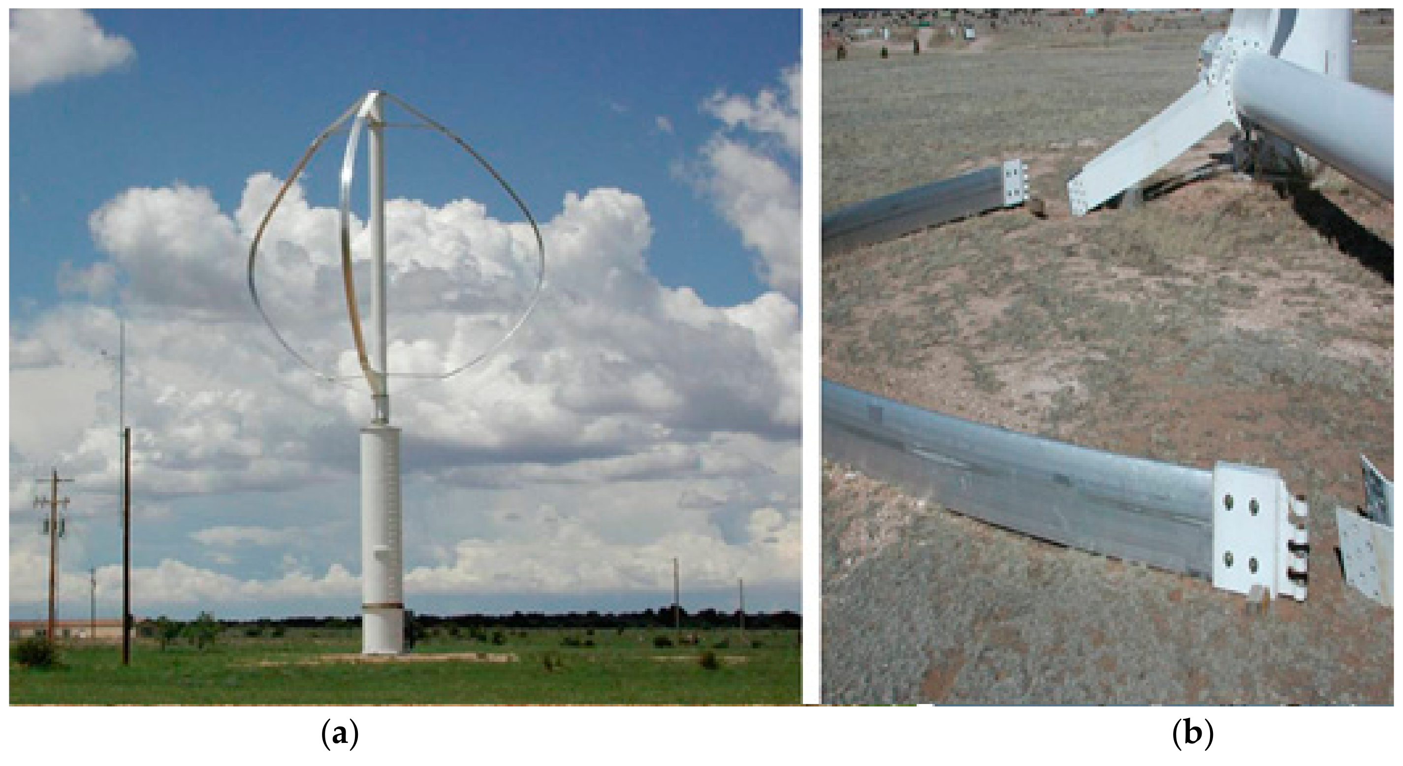
The first large scale turbine was built in Magladen Islands, Canada with a power capacity of 230 kW, as seen in Figure 2a. The turbine was manufactured by DAF Indal, manufacturer of aluminium products along with Hydro Quebec with the guidance from CNRC. The rotor diameter was 24 m [14] with a cross-sectional area of 595 m2. The fixed speed of the two-bladed turbine was equipped with an induction generator driven by the belt. The blade-mounted spoiler has been heavily researched on this turbine as displayed in Figure 2c. The spoilers are mounted on the mid of the blade but later raised doubt on their reliability. The turbine; however, required mechanical brakes and could not rely solely on on-air brakes [15]. The turbine crashed to the ground when it was not engaged with the drive train. On the positive side, the self-starting capability of the turbine was proven, which was previously assumed that the turbine was not capable of starting on its own. The turbine was put to rest in 1988 after 11 years in operation [12].
In 1984, DAF Indal built the 6400 model with a power capacity of 500 kW [16]. The first unit of this series was owned by Southern California Edison Company (SCE) and installed near Palm Springs, California. The second unit was owned by CNRC and installed at the Atlantic wind test site in Prince Edward Island, Canada [17] with a 36 m rotor diameter that rotates on hydraulic lower and upper bearings. It is supported by three pairs of galvanised bridge strand guy wires while the gearbox serves as the pedestal. The blades are aluminium extruded of NACA 0015 profile. The rotor shaft drives the bull gear, and the required generator speed is achieved in a single transmission. The bull gear also acts as the brake disc actuated by 16 hydraulic brake pads. The pinion gear mesh is automatically spray lubricated, and the pinions are mounted in spherical seats which permit self-alignment. Two independents, centrifugally actuated overspeed valves, are mounted on the rotor column [18].
In the event of rotor overspeed and failure of the primary overspeed sensing and protection system, the valves release hydraulic support pressure, thereby causing the brakes to be applied [19]. Apart from the 500 kW model, DAF Indal developed 50 kW turbines known for their reliability, as shown in Figure 2b [20]. The turbine installed on Vancouver Islands has been in operation for 16 years [21]. The turbine installed at Prince Edward Island suffered blade failure in 1985, bringing the Darrieus turbine development by DAF Indal to a halt. Apart from the blade fatigue issues and the torque ripple, which are an inherent nature of the Darrieus turbines, DAF Indal turbines are promising.
3.2. Sandia National Laboratories
Sandia National Laboratories was assigned by the US Department of Energy (DOE) to conduct research in search of alternatives to fossil fuels. The research on wind turbines started in 1970 with a focus on Savonius and Darrieus turbines, soon after SNL focused on Darrieus turbines for its efficiency. Various configurations of Darrieus turbines are studied and tested through prototypes. Two successful prototypes are commercialised by private entities such as FloWind with minor variations. The two-bladed 17 m model can generate 60 kW at rated wind speed of 13 m/s [22]. The rotor is supported by top and bottom thrust bearing. The rotating tower shaft is connected to the gearbox and in turn connected to the synchronous generator through a timing belt. The turbine is tested with both aluminium and composites blades [23]. The aluminium extruded blades are of NACA 0015 profile, whereas the composite blades are NACA 0012 profile. The performance difference between aluminium and composite blades are almost similar, without a noticeable difference. Pin joint supports and struts were required to support the blades on the blade shaft [24].
The aluminium extruded blades though thicker, it offers significant cost savings over composite blades and the elimination of struts [25]. The struts are of similar airfoil profile extends up to 67% of diameter radius. By comparing the strutted and unstrutted blades, it was found that struts cause significant parasitic drag resulting in a coefficient of performance (Cp) loss. There is a clear difference exhibited between the aerodynamic performance of the Sandia 17-m VAWT fitted with unstrutted and strutted blades, as shown in Figure 3a,b, respectively. Extruded unstrutted aluminium blades demonstrate higher Cp compared to the strutted composite blades.
With the successful testing of the 17 m model, Sandia moved on to build large Darrieus turbine of the 34 m diameter model under the “Test-bed” program in 1988 [26]. Rated at 500 kW at 12.5 m/s is a two-bladed turbine equipped with a synchronous generator and variable speed gearbox [27], as shown in Figure 3c. The generators operate at 1800 rpm, and with the pulleys, belt, and transmission ratios, the turbine could be operated from 29.6 to 59.5 rpm in thirteen discrete steps. The guy wired phi rotor blades are manufactured through aluminium extrusion as three sections. The root, transition and equatorial sections are made of NACA 0021, SNL 0018/15 and SNL 0018/50, respectively [28]. The tailored airfoil for different sections adds structural strength by reducing the localised edgewise bending, reduce the blade fatigue and increases aerodynamic performance [29]. With these improvements, the unstrutted design reached a maximum power coefficient of 0.43 [30]. The SNL was allocated with a $4.1 million [31] grant for the development of a multi-megawatt Darrieus turbine for offshore power generation in recent years.
3.3. ALCOA
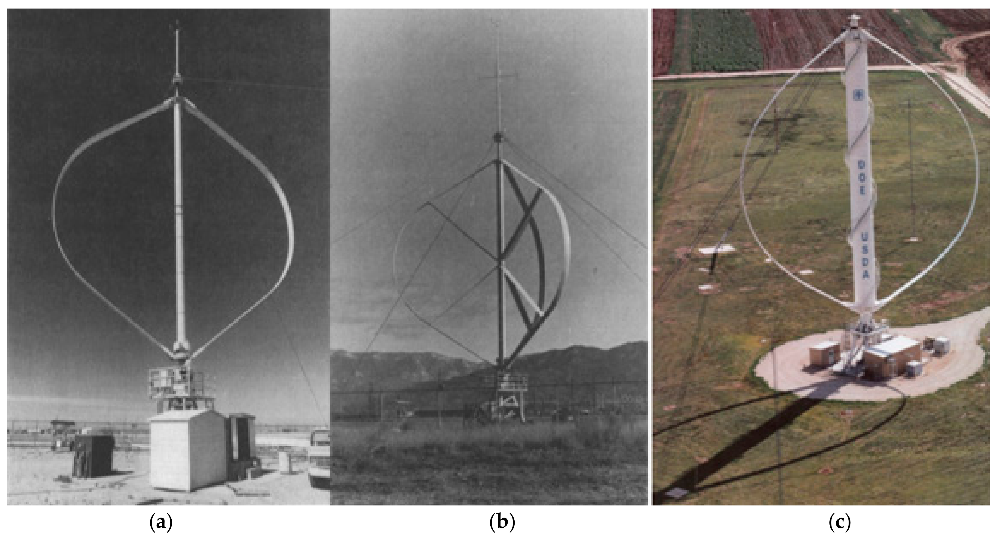
Aluminium Company of America (ALCOA), which originally manufactured blades for SNL in 1975, began developing VAWT based on the SNL technology. ALCOA developed ALVAWT, a 100-kW capacity turbine of 17 m in diameter was rated at 14 m/s with the sept area of 279 m2, as shown in Figure 4b,c [32]. The three-bladed turbines have an induction generator with a fixed speed gearbox. The ALVAWT 100 was one of their successful models, reliably operated under stormy conditions. ALCOA further developed ALVAWT 500 in the year 1981 of a rotor diameter of 25 m and rotor height of 37.5 m. Between 1979 and 1981, ALCOA erected its pre-production of the 25 m, 500 kW design for the Eugene Water & Electric Board near Newport, Oregon, as shown in Figure 4a [32]. The three-bladed machines installed in Pittsburg, US collapsed due to a control system fault. The early failures pushed ALCOA to recall its turbines leading to the termination of VAWT development.
3.4. Adecon, VAWT Power and Vestas VAWT
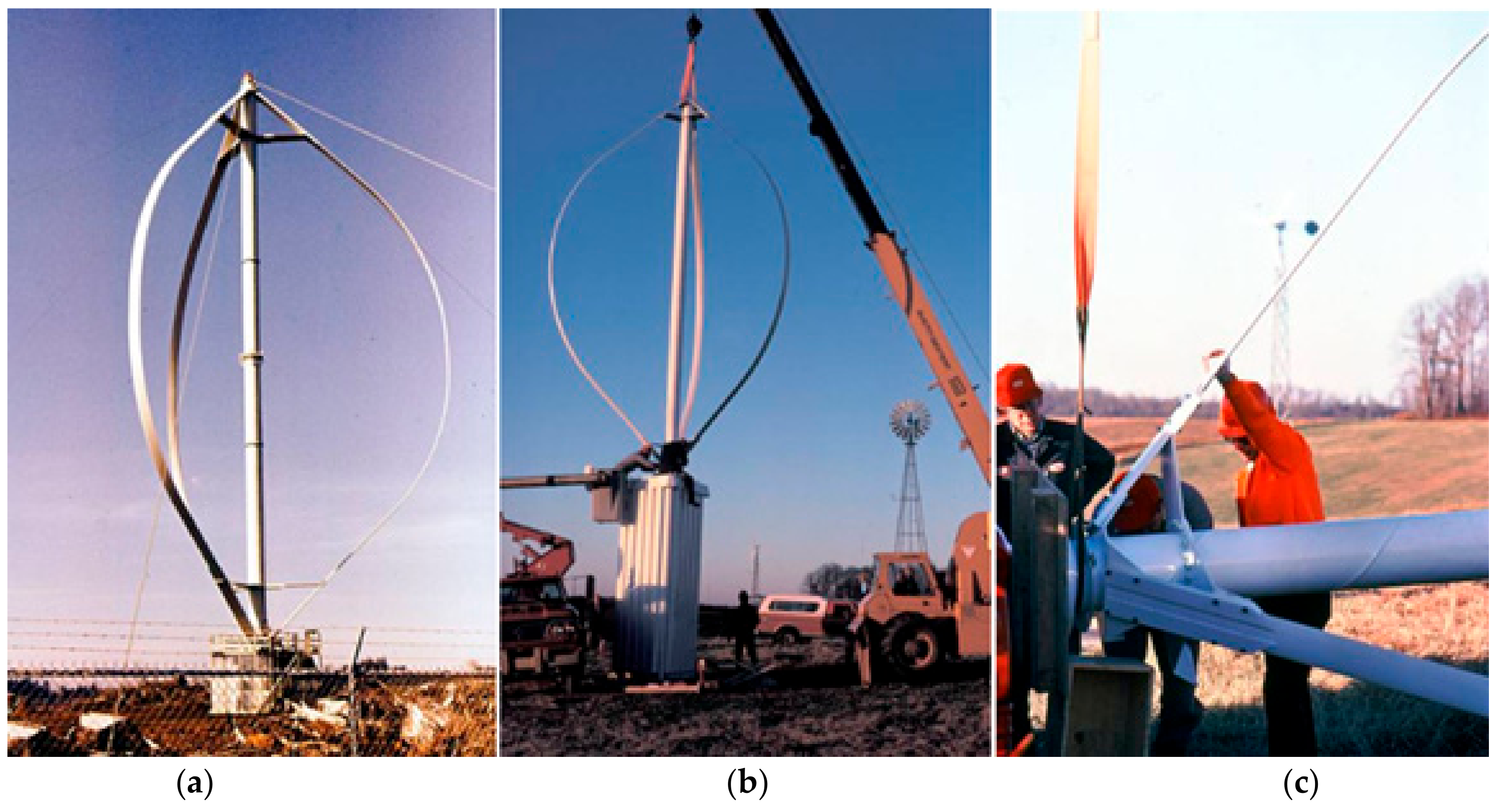
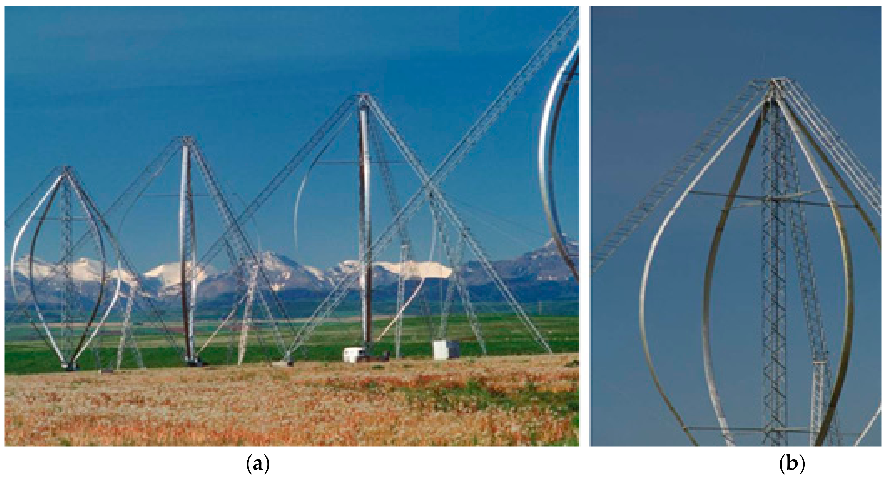
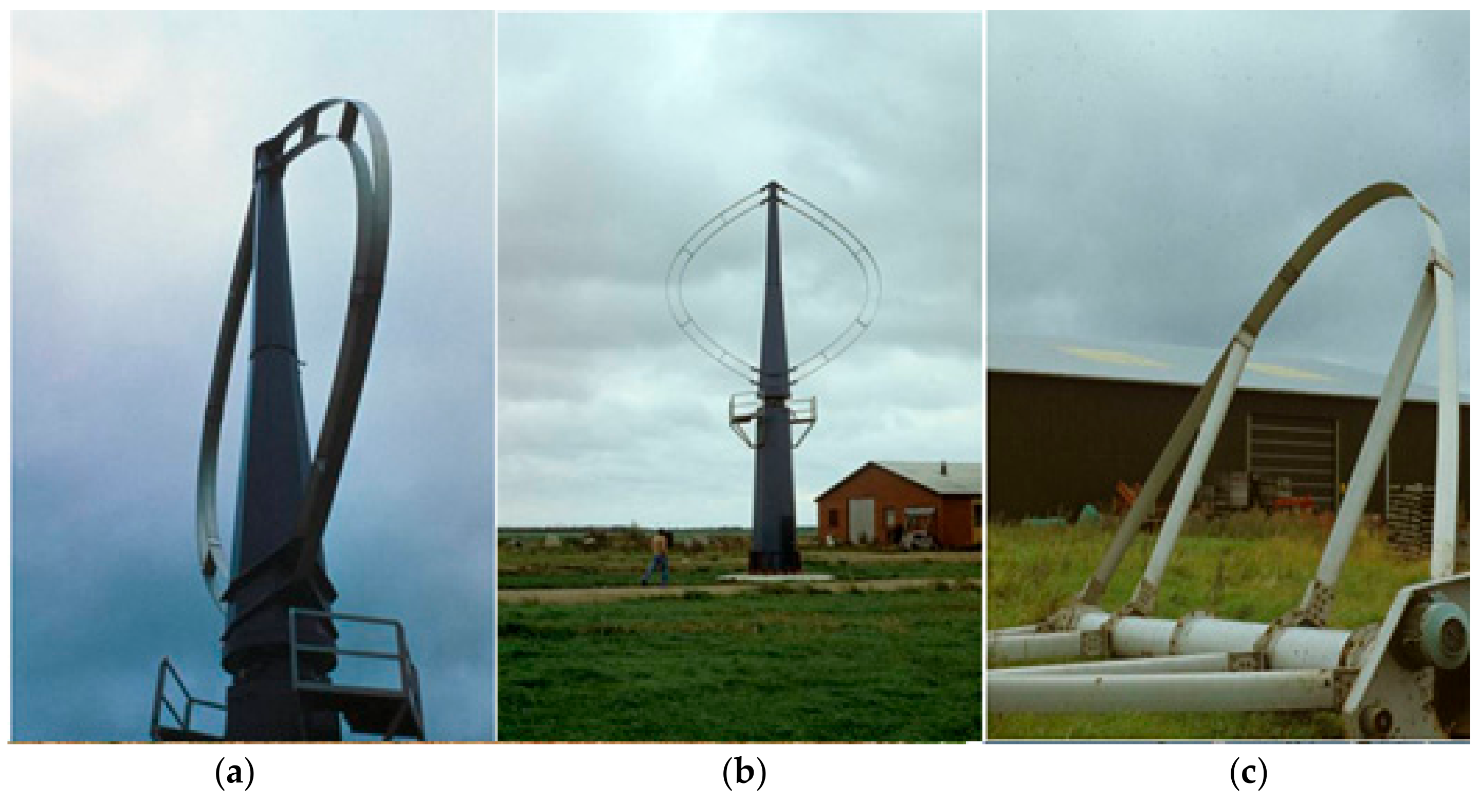
Adecon started developing VAWTs in the late 1980s led by Peter south. The initial 125 kW machine is 17 m in diameter and was supported with lattice masts instead of guy cables to reduce the footprint. The turbine failed due to over speeding, similar to other turbine models. Later, the rotor was redesigned by CWT Power with four blades using the lattice frame that was used instead of the torque tube with lattice masts. Ten of such turbines are installed in Alberta, Canada and two crashed to the ground due to the resonance of the lattice frame and metallurgical failures ending the Adecon development of VAWTs [33], as shown in Figure 5a,b. VAWTPOWER developed 185 kW and installed 40 turbines which operated successfully until 1985. The latest version of the cantilevered prototype is shown in Figure 6a,b [34] rated at 60 kW. Little is known about the 9 kW double-bladed turbine developed by Bjervig and later bought by Vestas, as seen in Figure 7a,b [35].
3.5. FloWind
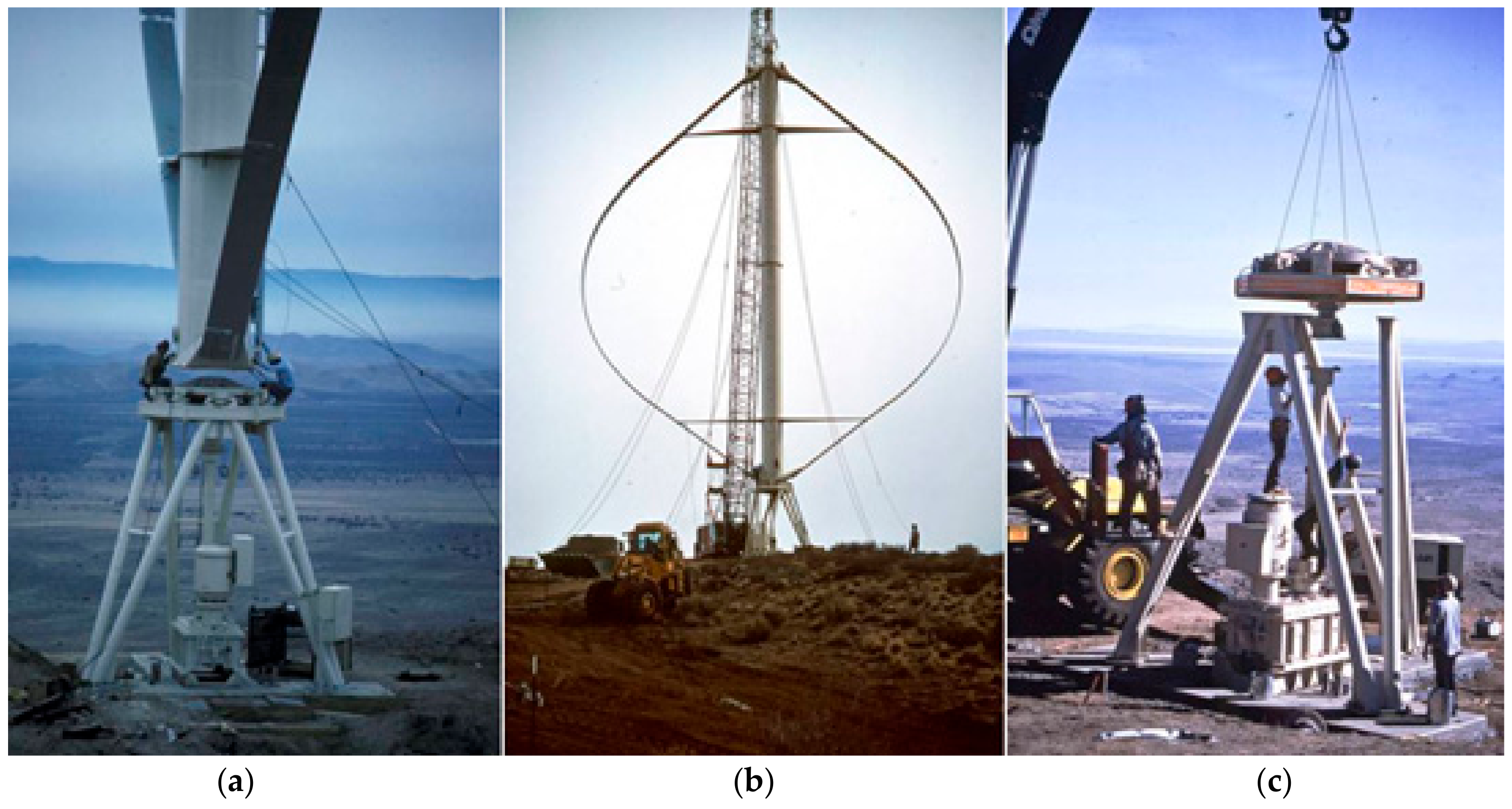
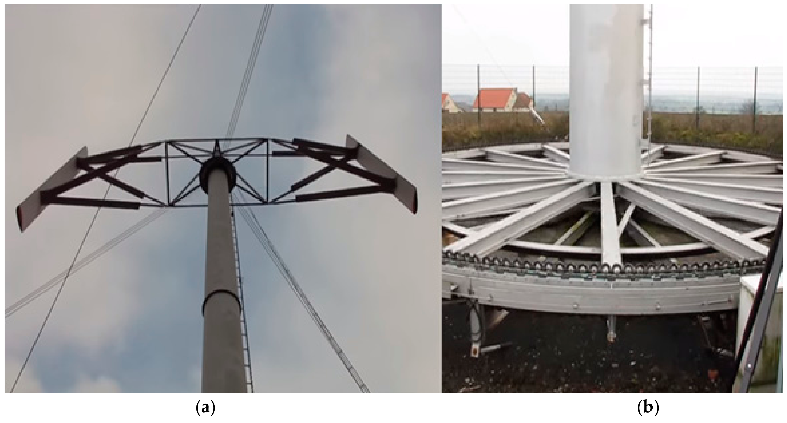
Successful testing of the Sandia Test-bed program in 1989, lead to the commercialisation of the design. The pre-commercial version was named as the Point design and has been introduced to the private industries. FloWind built and operated the 17 m and 19 m model based on SNL technology [36]. The 17 m indicates the rotor diameter sweeping an area of 260 m2 with a height of 23 m. The 19 m model has swept the area of 316 m2 with a rated capacity of 300 kW at 20 m/s. The rated wind speed of 17 m/s and 20 m/s for 17 m and 19 m model, respectively, are relatively higher for onshore turbines and the turbines never achieved the rated capacity in their operational period. The tower, rotor, and the drive train details are shown in Figure 8a–c [37]. The 300 kW machine used an SNLA 2150 airfoil and a retrofit gearbox that increased the turbine’s rotation rate to 60 rpm [38]. The Retrofit gearbox led to an early failure and subsequent prototypes which were then replaced with original F-19 gearboxes that reduced the rpm to 52 rpm. New airfoil named S82435 was conceived, as the SNLA 2150 airfoil was not able to meet the FloWind requirements. The initial version of S82435 buckled as the blade walls were too thin to withstand the bend-in-place and operating stresses. The blade was redesigned with thicker walls and blades of this design were used in the commercial version. Struts were required to stabilise the rotor and were constructed in V-shape and flanged to the tower. The 80 mm and 102 mm diameter pipe struts are not aerodynamically faired and hence produced significant aerodynamic drag, curtailing 25% of power production at medium wind speeds [39]. When aerodynamically faired, the performance increases by approximately 15%.
To increase the output power of the rotor, the extended height to diameter (EHD) version was designed. The EHD design achieved larger swept area by stretching of the rotor vertically, rather than by stretching its diameter. The EHD design minimised the bend-in-place static stresses compared to a lower height-to-diameter rotor. The braking system was one of the highest maintenance items on the FloWind fleet. The final system design utilised two sets of the hydraulically applied brakes. A third, fail-safe parking brake set was also incorporated in the braking system. Aluminium blades used in commercial turbines are not able to withstand fatigue failure due to cyclic stress [40]. The failure of blades in the 19 m model severely degraded the company’s reputation and pushed it to the verge of bankruptcy. FloWind introduced three-bladed fibreglass blades [41] through the EHD version, which also failed at high winds paving the way to the end of its development. FloWind installed and operated over 500 turbines at Altamont Pass in California during its peak. All the FloWind turbines were out of operation by 2004, and the last turbine was dismantled in 2010 to be replaced with Vestas HAWTs.
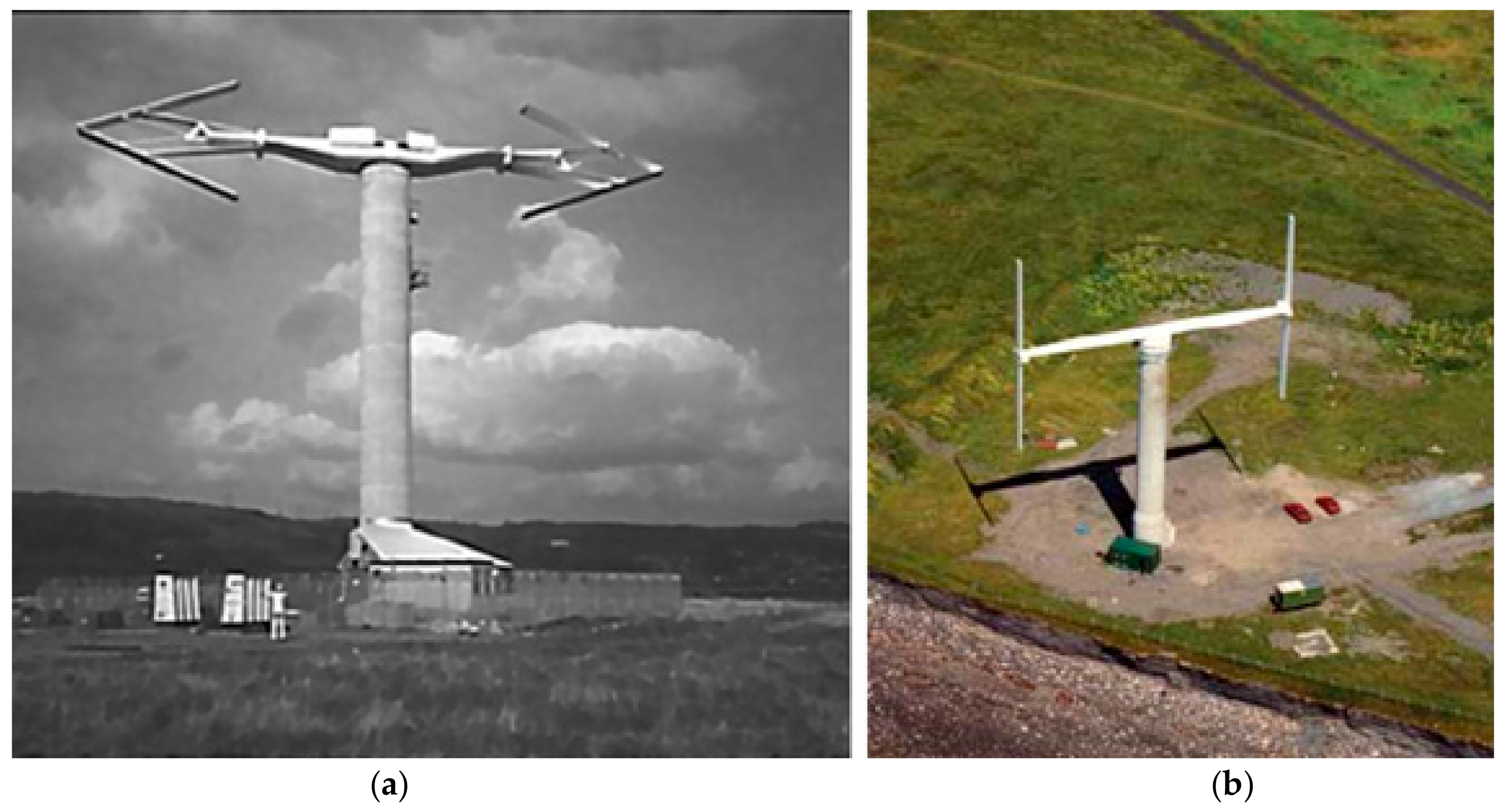
3.6. EOLE and Heidelberg
The EOLE was installed in 1987 in Quebec, the largest VAWT ever built. Rated at 3.8 MW, the direct drive synchronous generated operates at 14 rpm [42]. Blades are made of steel core and achieve the rated 3.8 MW. Though the turbine was operated at reduced rpm of 12, the failure of the bottom-bearing halts its operation as shown in Figure 9a–c [43]. Heidelberg motor GmbH developed a two-bladed direct drive 300 kW machine with rotating tower [40]. The ground-mounted generator of large diameter eliminated the transmission system. Later, the design was revised with a permanent magnet generator mounted on top of the tripod. Out of five turbines installed, one of the turbines destroyed itself due to the strut welding failure. The aerodynamic efficiency of the tripod-based machine is substantially low due to the parasitic drag from the struts. Heidelberg then developed 20 kW machines with installations in Rwanda and German Alps, which operated more than 15 years, as shown in Figure 10a,b [44].
3.7. Musgrove Turbines (VAWT 450 and VAWT 850)
Investigation of the H-rotor at the University of Reading, UK began in 1975 lead by Peter Musgrove. Together with his student Ian Mays, Musgrove [45] validated the novel concept to regulate the over speeding of the H-rotors and its feasibility for the multi-megawatt turbines. The initial VAWT design and development work was carried out by a consortium comprising the British Aerospace Aircraft Group (Bristol), Taylor Woodrow Construction Ltd. and Reading University [46]. The largest Musgrove turbine built and tested at Reading University is 3 m in diameter, limited by the wind tunnel size available at the University of Reading. The variable geometry two-bladed turbine was rated at 130 kW at 11 m/s. The rotor diameter is 25 m with a swept area of 450 m2. The conventional NACA 0015 airfoil for the blade length of 18 m allows the turbine to rotate at a maximum rpm of 27. The generator and the transmission systems are mounted on the ground. The turbine shaft is connected to two induction generators of capacity 75 kW and 30 kW [47]. The 30 kW generator will be engaged during low wind speed and both the generators are engaged during high winds. The turbine is equipped with automatic reefing system that will reef the blades, taking the shape of a double head arrow effectively decreasing the swept area if the wind speed is above 30 m/s. The turbine in the reefed position is shown in Figure 11a [48]. But later in 1988, data collected from 200 sensors for the period of two years revealed that the reefing system was unnecessarily complex as the power control was automatically achieved by the natural passive-stalling of the airfoils, even in strong winds with the blades remaining vertical. Hence, the variable geometry system was dropped during scaling to 500 kW model (VAWT-850). In the meantime, before the installation of VAWT-850 turbine, VAWT Ltd. built a 17 m diameter, 100 kW VAWT (VAWT-260) demonstration project on the Isles of Scilly, and Sardinia [7]. The Isles of Scilly were chosen because the islands are not connected to the grid and it was expensive to rely on the diesel generator for desalination. With funding from the European Commission, the VAWT 850 model of 500 kW capacity was built and erected in 1990 at Carmarthen test. The VAWT 850–500 kW turbine is shown in Figure 11b [49]. The rated 500 kW turbine with a rotor diameter of 38 m is achieved at a higher wind speed of 18 m/s [50], which is available only at a handful of sites or in offshore locations. The turbine usefully operated only until the 26th February 1991 when one of the blades broke, due to an error in the manufacture of the fibreglass blades. Though the design is simple, the VAWT 850 model is not as cost-effective as it was claimed before. The large concrete tower has to withstand the cyclical loads generated by the blades. Later, Musgrove emphasised that the VAWT with the blade pitch control are cost-effective than the HAWT for the turbines of capacity more than 20 MW.
3.8. Aerogenerator
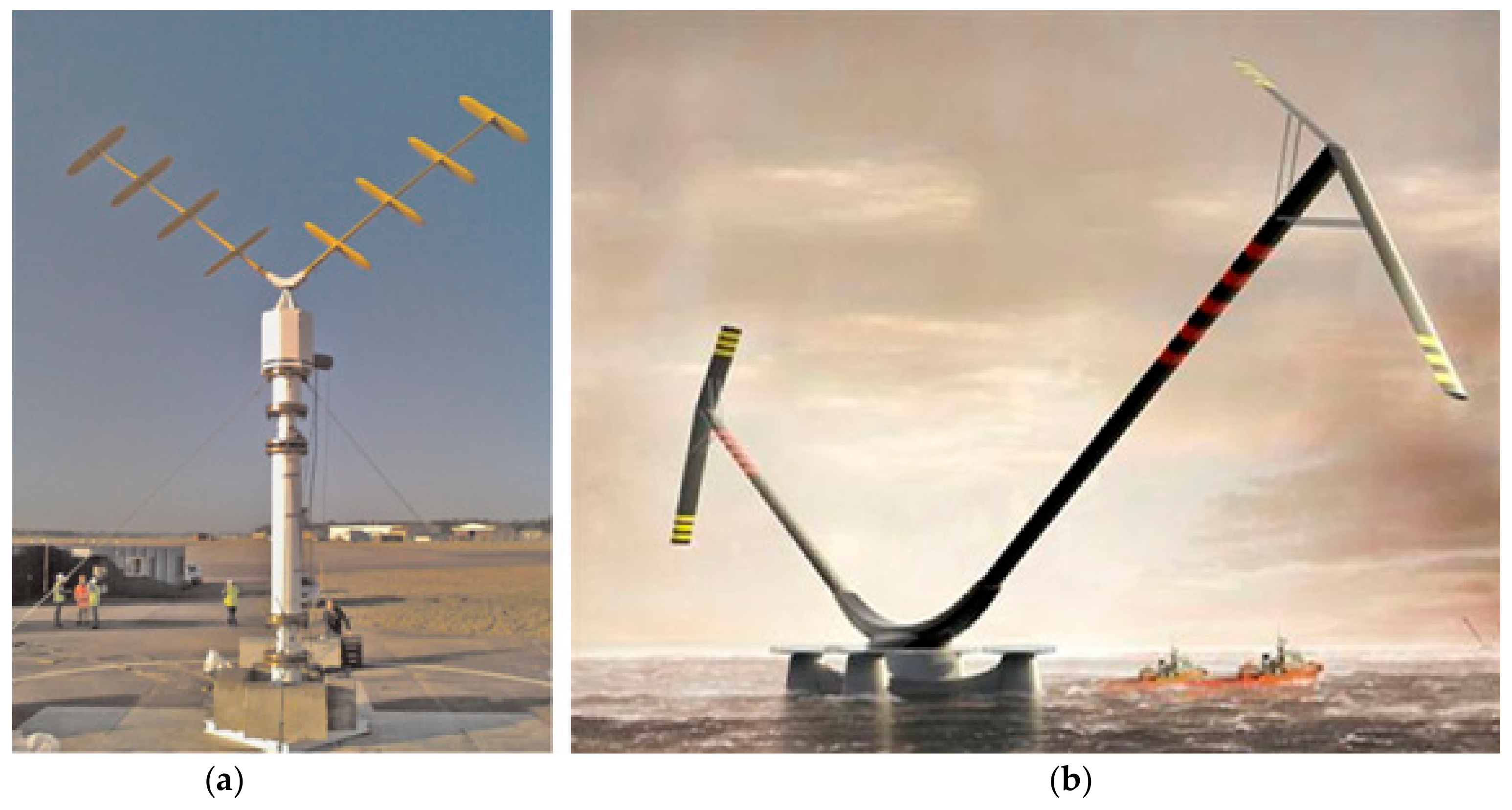
The aerogenerator concept was originally proposed by David Sharpe and later adopted by Wind Power Ltd. Aerogenerator evolved from the successful test of a 5 kW two-bladed V-rotor prototype in 1987 by David Sharpe and Derek Taylor. Following the testing of the twin-bladed machine, they also proposed a mono V-VAWT consisting of one inclined blade with associated balance weights mounted on a teetered hub above a relatively short support structure. The single cantilevered blade was predicted to improve performance with a lower cost of manufacture. Wind Power Ltd. currently holds the patent for the aerogenerator, which was further developed through Novel Offshore Vertical Axis turbine (NOVA) project [51]. The original NOVA concept pictured in Figure 12b [52] featured four sails per arm, positioned such that no sails overlapped at any given height in order to minimise losses due to sail–wake interactions [53]. However, this requirement results in low-aspect-ratio sails that are less efficient owing to higher induced drag and tip losses and higher interference drag due to the number of junction regions. Furthermore, analysis of this profile showed that the lower sails contribute significantly less torque owing to their lower elevation and angular velocity. Consequently, all design optimisation studies focused on one and two-sail designs. The objective is to develop a 10 MW offshore cost-effective wind turbine with increased energy yield for 5 GW wind farm planned for 2020. Initially, for the aerogenerator, two support structures are considered, a fixed jacket structure for the low water depth offshore locations and semi-submersible structure for the greater water depth. Both the designs are evaluated for hard ocean waves and storm conditions up to 70 m/s [54]. The results provide a valuable conclusion that the drive train and bearings can be bypassed by directly engaging with the drive shaft during the survival mode. Also, it was found that the camber and thickness of the airfoil do not significantly affect the performance, and hence conventional symmetric NACA series are opt for the Aerogenerator. The proposed 10 MW aerogenerator is 270 m in diameter and 120 m in height rated at 13 m/s with drive train efficiency of 88%. In order to validate the design, a prototype of 5 kW was installed, as shown in Figure 12a [52]. The 5 kW model consists of two arms of a V-shape with four sails, each with guy wires connecting the arms to reduce the bending stress. Whereas the full-scale model enhanced by Grimshaw architects does not have guy wires. During the design phase, the final 10 MW aerogenerator design was scaled by approximately 70% to a 5 MW design for comparison with an existing Repower 5 MW HAWT turbine [54]. The aerogenerator design operates at a significantly lower elevation than the HAWT and still achieves reasonable aerodynamic efficiency with a power coefficient of 0.38, and with a significantly lower overturning moment and centre of gravity than the HAWT.
3.9. Vertical Wind AB
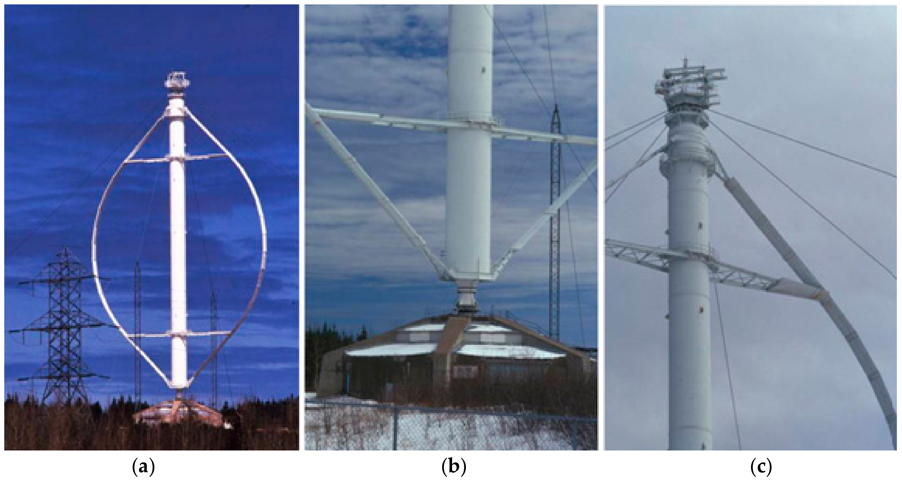
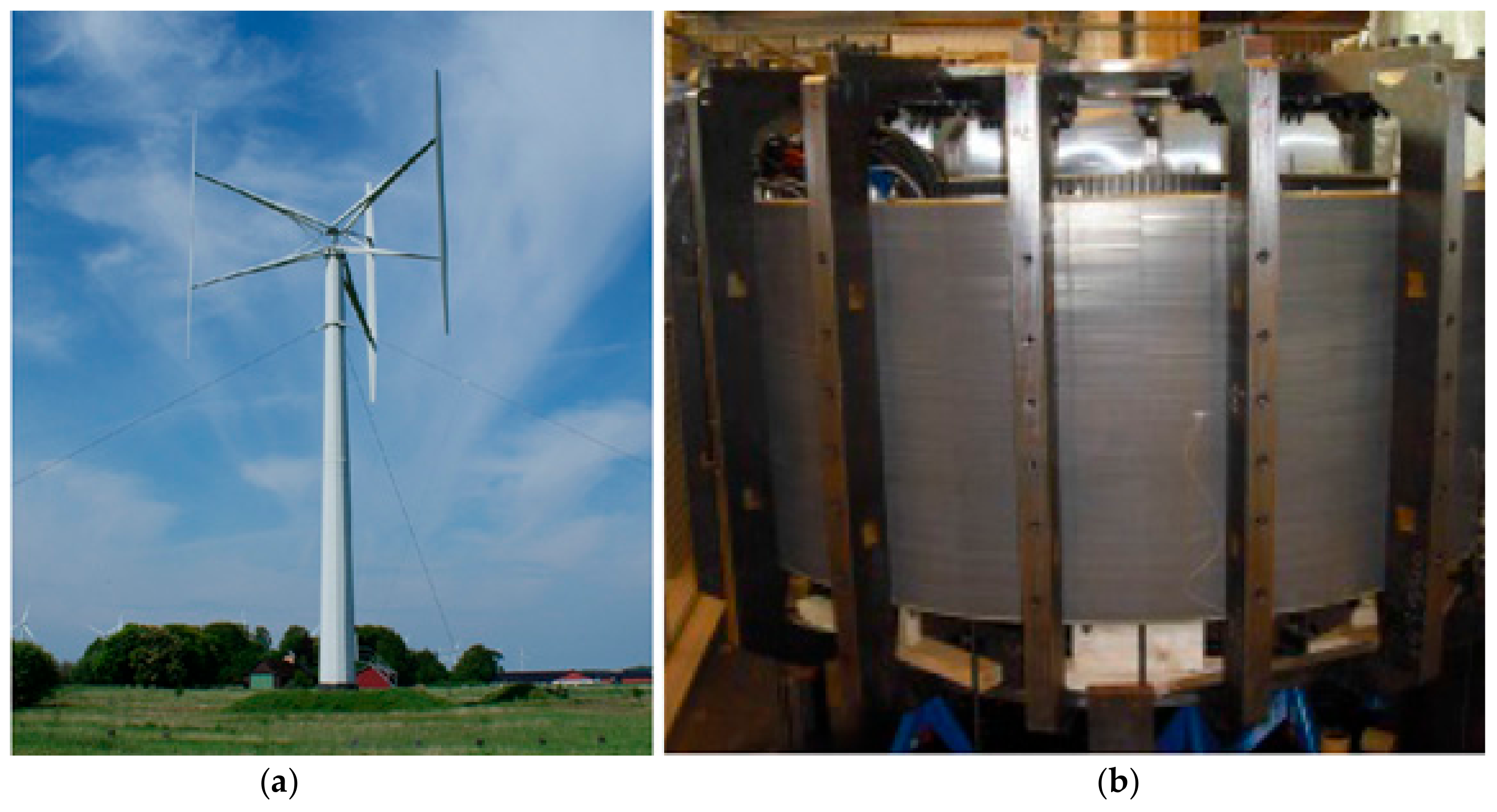
A 200 kW prototype was installed in 2010 by Vertical Wind AB [55], which is a spinoff from Uppsala University. A decade of research on H-rotors led to the development of 200 kW prototype installed at Falkenberg, west coast of Sweden. The turbine diameter is 26 m with a blade length of 24 m sweeping an area of 624 m2, as shown in Figure 13a [56]. Researchers at Uppsala university identified that the primary failure in VAWT is gearbox, and direct drive will curtail the downtime and maintenance cost by eliminating the gearbox. Hence, the focus is on the design of the direct drive synchronous generators suitable for H-rotors. The 36-pole generator developed, as shown in Figure 13b [56], was made of a neodymium-iron-boron permanent magnet rotor to withstand high overload capacity. The variable speed control is achieved by connecting the generator to the frequency drive. The concept of using the generator as a motor to start the turbine was extensively researched on this turbine. A separate auxiliary winding [57], other than the main winding, has been introduced with electrical connectors to switch between starting the generator and normal operation. The auxiliary winding has been previously tested in the 12 kW prototype, which enables the turbine to start at 0.5 m/s. In addition, the generator acts as the primary brake, before applying the hydraulic brake in case of emergency and parking. The generator has been placed on the ground with the steel shaft connecting the rotor to the generator and held in place by bearings on top and bottom. The blades and struts are made of fibreglass, whereas the tower is made of wood covered by fibreglass. The lower price to strength ratio provides the ability to withstand high wind loads during storm conditions. Though the initial design was without guy wires, three guy wires have been added as the cracks begin to appear on the wood-laminated tower due to the wrong selection of glue. When designing a wind turbine tower, different strategies are used to avoid resonances due to the dynamic loads. The tower could be made stiff or soft to alter the eigenfrequency which can be above three-fold of rotational rpm or eigenfrequency in the range of rated rpm. The addition of guy wires decreases the maximum rpm from 33 to 23 limited by the eigenfrequency [58]. The enoise generation from the turbine has been studied in detail. The test results show that the noise frequency for 200 kw turbine is in the range of 600–1200 Hz [59], which is at the same frequency of environmental noise. Noise emission at 8 m/s at 10 m above the ground surface is 96.2 dBA, whereas the noise level for 6 m/s is 94.1 dBA. It was also found that trailing edge vortex and the turbulence is the key source of noise in the H-rotor [60]. The noise propagation study shows that noise from VAWT decreases rapidly compared to a similar size HAWT [61]. The development came to halt when the key investor pulled off. Vertical Wind AB is currently involved in manufacturing generators for other turbine manufacturers.
3.10. Skwid-MODEC
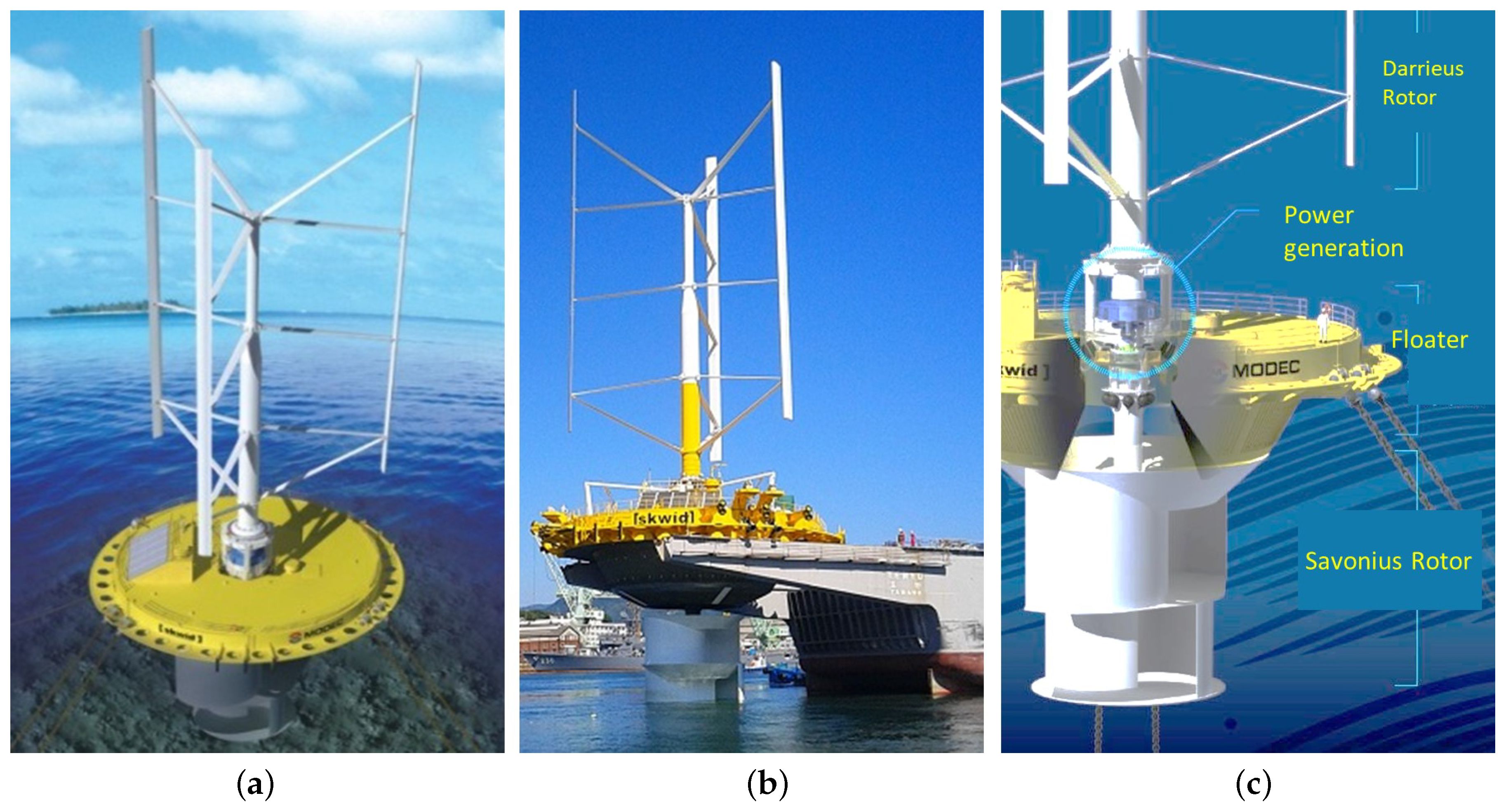
Mitsui Ocean Development & Engineering Company (MODEC), an offshore technology company specialised in floating oil and gas platforms, has developed Savonius Keel & Wind Turbine Darrieus [62] (skwid). The turbine is developed for offshore power generation by leveraging their expertise in designing floating structures. The turbine is unique in a number of ways, which is the first of its kind to harness the wind and tidal energy in a single device, as shown in Figure 14a [62]. MODEC claims that the annual energy yield increases double-fold to be a cost-effective offshore solution. The wind energy is extracted through a Darrieus rotor, whereas the weak ocean currents are harnessed by a two-stage Savonius rotor. Two stages increase the direction capability and generation of the smooth torque. The rotating tower of the Darrieus rotor and the Savonius rotor are in line and connected through the gearbox. The Savonius rotor can initiate a rotation in Darrieus rotor enhancing the start-up performance, after which it continues to generate the power as a stand-alone unit. The individual rated capacity of the turbines is unavailable, yet the combined rated capacity of the hybrid turbine is specified as 500 kW at 13 m/s, while the Savonius turbine is rated at 60 kW. The weight of high solidity Savonius rotor with bottom endplates acts as a ballast to keep the Darrieus rotor in an upright position. The gearbox and the generator are housed inside the floating platform, as shown in Figure 14c, and attached to the rotating tower through a gimbal-like structure. This allows the platform to align with waves despite being attached to the seabed through mooring lines. As the Savonius turbine are low tip speed ratio machines, the manufacturers claim that it is safe for marine life. Each blade of the Darrieus rotor is supported by five struts to withstand the harsh offshore conditions.
Though the concept was novel, serious errors during installation halted the further development of the turbine. The installation site of skwid is off the coast of Kabe Island, Japan. As the Savonius rotor is known for its high thrust loads [63], the rotor shaft breaks sank into the sea, while it was towed to the site [64] since it is submerged while towing as shown in Figure 14b. The rotor was retrieved and recommissioned in 2014 [65], and the second attempt was made for a successful installation. But this time, the whole platform sank due to unbalanced anchoring, raising questions on the turbine’s capability for the offshore conditions. MODEC announced on May 2015 that the prototype had been successfully salvaged and the project has been abandoned. Savonius turbines can be potentially replaced with novel designs for low current power generation, such as turbines with trapped vortex airfoil [66]. The turbine should have been a game-changer as a cost-effective offshore VAWT if it was successfully installed and operated.
3.11. VertAx Wind
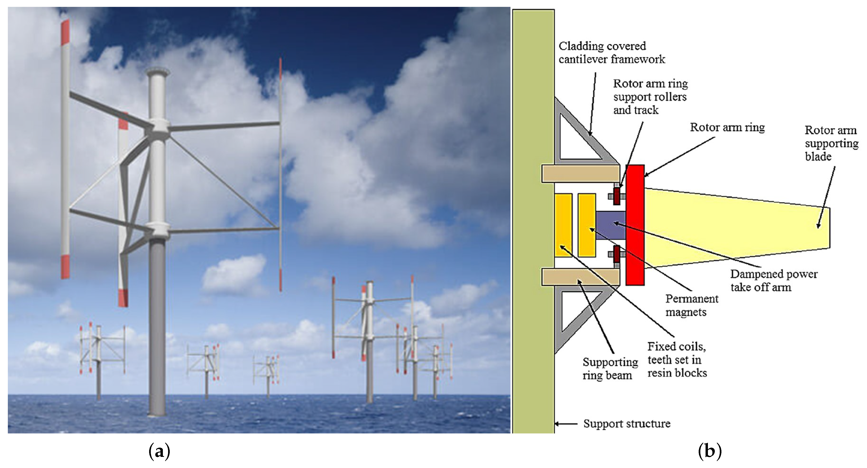
VertAx wind [67] limited was established in 2007 with the objective of developing an offshore wind turbine for substantial cost-reduction and to re-establish the wind turbine manufacturing activity in the UK. The key area of research is low maintenance cost, longevity, and reliability. The consortium was formed focusing on each element of the turbine and leveraging the expertise to develop a reliable offshore turbine. The proposed three-bladed Darrieus VAWT has a rotor diameter of 140 m and blade height of 110 m with a maximum power capacity of 10 MW, as pictured in Figure 15a. VertAx wind collaborated with Slingsby composites and the Northwest Composite centre for blade manufacturing. In order to ease the logistics, the blades are manufactured in segments of 11 m each and assembled onsite. The support arms are also manufactured by composites to reduce the mass and parasitic drag. Blade profiling and aerodynamic optimisation are carried out at the University of Leeds [68]. VertAx wind claims to have reduced the vortex-shedding effect through novel blade profile.
Notable innovations have been introduced in the design of generators by collaborating with the University of Edinburg. The C-Gen technology developed by Mark Muller [69] has been employed. The modular permanent magnet ring generator has a C-shaped core material, while the stator disks pass through the C-limbs [70]. The cogging torque is a vital factor in influencing the start-up characteristics of VAWT. The poor starting capability could be directly linked to the higher cogging torque from the generator. The C-Gen generator has zero cogging torque allowing the turbine to start early, and thus, increasing the annual energy yield. The C-Gen was well established for marine turbines and wave energy converters, which has been progressively developed from 15 kW to 1 MW. Two generators have a strut joining portion and is rated at 5 MW each with 180 poles at 4 RPM.
Manufacturing of ring bearings is a challenge for the multi-megawatt VAWTs which has been circumvented by using rollers and track as shown in Figure 15b. The struts are connected to the roller structure and revolve around the tower. Dynamic modelling of VertAx turbine tower and structure was carried out by the University of Cranefield. The turbine is designed for 25 years of life and facilitated with an onboard crane for the blade and roller replacement [71]. The hydraulic ram of the crane is supported on the tower top without any interference with the other components of the turbine. The helipad is provided on the top of the tower to accommodate a 4–6-seater helicopter. The turbine can be completely assembled on-site and can be transported to the location. Though the turbine floating platform has been discussed in detail, a single spar type is most suitable compared to articulated multi-spar as the overturning moment is comparatively lower. As of now, VertAx 10 MW turbine has not been installed.
3.12. Vertiwind
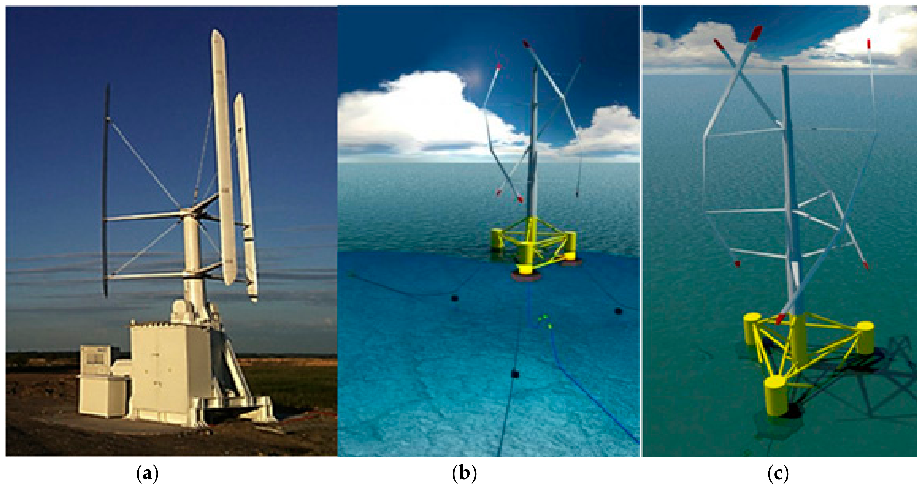
The Vertiwind project was initiated by the French government in the year 2011. The objective is to develop a reliable and economical offshore wind turbine as an alternative to the conventional HAWT. The consortium was setup between Technip, a leading oil and gas firm with expertise in offshore engineering with Nenuphar, the company with expertise in wind power research overseen by EDF energies. The research on the development of 2 MW turbines starts with the prototype development of 35 kW Darrieus VAWT onshore turbine, as pictured in Figure 16a. The objective of the prototype is to test the modified blade structural properties and the struts. The Vertiwind researcher identified torque pulsation and the parasitic drag due to the studs are of primary challenges that need to be addressed in order to develop a robust and efficient offshore turbine. The parasitic drag by the supporting arms is curtailed by the novel supporting method in which the bottom one third of the blade is rigidly supported by arms, whereas two thirds of the top blades are supported by the struts to counter the centrifugal force of the blades. Although Vertiwind claims to have reduced the parasitic drag, the proposed design was not carried over to 2 MW turbine due to vibrations from the unsupported blade length. Hence, the 2 MW turbine has conventional supporting arms. The helical rotors are known for its smooth torque generation compared to cyclical torque fluctuations of straight-bladed Giromill. Adopting a helical blade as such for the multi-megawatt blades is not viable due to the high blade manufacturing cost and logistics. Hence, Vertiwind attempts to achieve a near-helical shape with multipole segments of straight blades. The proposed helicoidal shaped blades with the floating platform are shown in Figure 16b,c [72]. Vertiwind claims that the improved design has enhanced structural properties and aerodynamic properties.
The floating platform of an offshore turbine shares a considerable cost of total turbine cost. The size of the platform is dictated by the overturning moment on the platform. In the case of HAWT, the overturning moment is high as the thrust force that acts at the hub, whereas for Darrieus VAWT, the thrust force is evenly distributed over the entire blade length. The over turbine moment is claimed to reduce by half just by adopting a vertical design. The ballast weight and the size of the platform are influenced by the nacelle mass. As the generator and the gearbox are located on the tower top, a heavier ballast is required for the turbine stabilisation in case of HAWT, whereas the placement of the drive train components at 20 m above sea level of Vertiwind turbines reduces the platform size extending only 9 m below sea level. With the above enhancements, Vertiwind claims to reduce the cost by 25% [73] from the direct savings of materials. Despite these achievements, Nenuphar failed to attract the investors for the development of 2 MW turbine and eventually liquidated on 2018 [74].
3.13. ANew Turbines
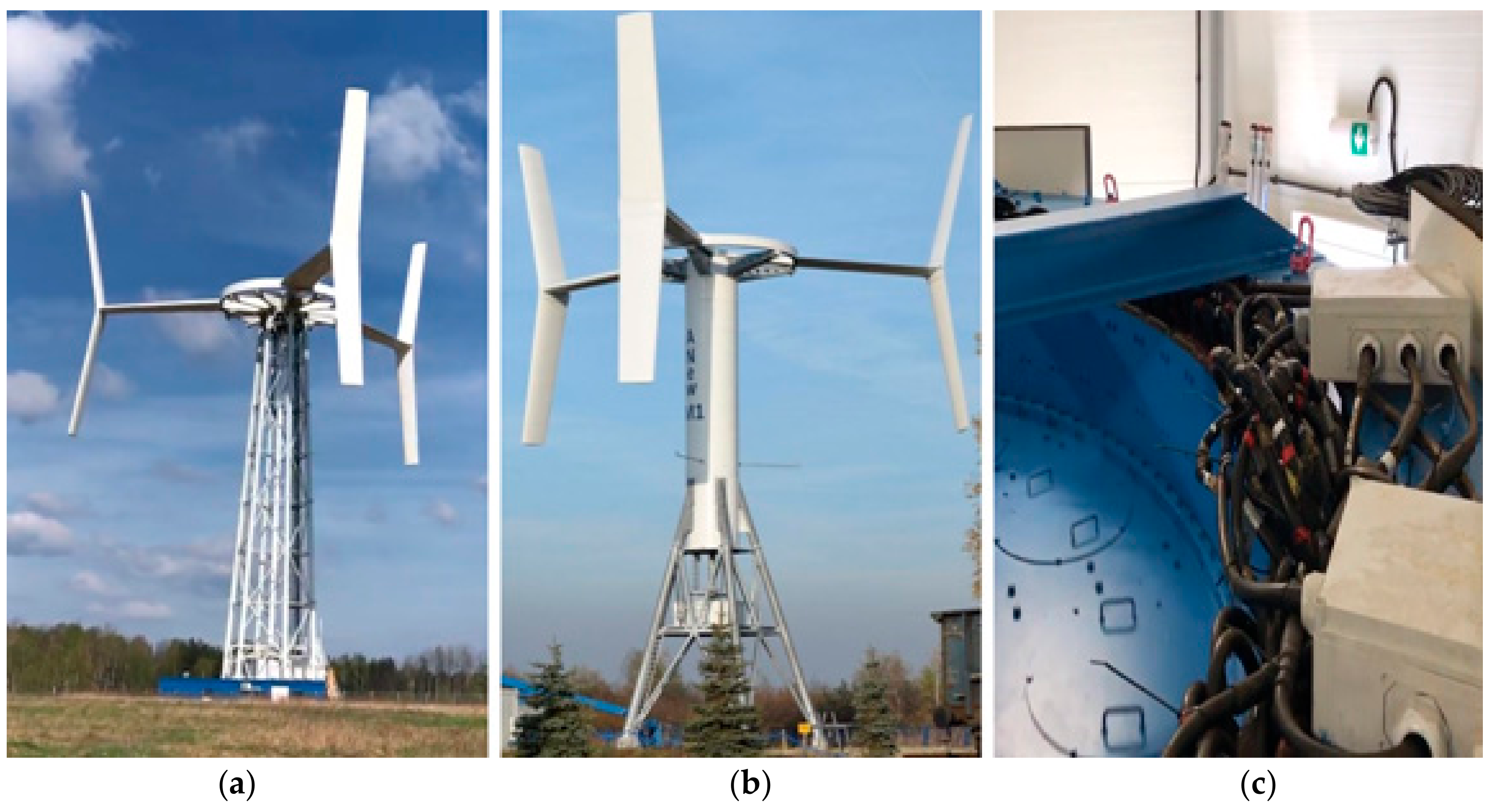
Anew institute from Poland is active in the development of the multi-megawatt Darrieus turbines, supported by Stalprodukt S.A. The first prototype, the 15 KW ANEW-S1 [75] model is three-bladed and optimised for low wind speeds of 3–9 m/s, as shown in Figure 17b [75]. The target market for these turbines is residential and farm use. The single struct per blade and the V-shaped blades stand out from the rest and form the basis even for the multi-megawatt turbines developed by Anew institute. The V-shaped blades are aesthetically pleasing and found to reduce the noise. Researchers at Anew institute demonstrated a multi-stage rotor of Darrieus type to address the torque fluctuations prevalent in the single-stage rotor. The two-stage rotor found to increase the starting capability of the turbine by eliminating the dead band. The test results unfolded the fact that efficiency is substantially reduced due to blade tip loss in a multi-stage rotor compared to a single stage.
The success of the ANEW-S1 led to the development of the 200 KW ANEW-M1 [76] model rated at 200 kW at a wind speed of 12 m/s. A cut in wind speed was claimed to be 3.2 m/s, which is by far the lowest for the medium-sized Darrieus turbines. The struts and the blades are made from fibreglass to reduce the weight. The unique large diameter generator design offers low cogging torque, as shown in Figure 17a,c. The generator is a direct drive type manufactured by Vertical Wind AB [77]. The turbine is able to generate the rated voltage of 400 VAC even at lower RPM of 34. The tower design of the 200 KW ANEW-M1 is unique with half a truss design to facilitate the mounting of the generator and half monopole design to reduce the turbulence on blades. The supporting ring is equipped with tracks on which the struts rollers are guided, thereby eliminating the need for larger bearings. The supporting ring, in turn, is firmly attached to the tower.
ANEW-M1 was further scaled to 1.5 MW ANEW-B1 [78] and has been under testing since 2017. The tower’s entire truss design was supported by six poles of pyramid shape. With the turbine diameter of 52 m and swept area of 1700 m2, the turbine is claimed to output 1.5 MW at 13 m/s. Maximum RPM is 16, while the maximum linear speed of the blade is 44 m/s. Though the turbines are one of the promising candidates for the megawatt-scale power generation, the maximum power coefficient achieved is questionable as there is significant blade tip loss due to the lack of end plates. Considerable reduction in parasitic drag was achieved by eliminating one strut with significant cost savings in materials and assembly time. As per the manufacturer, the blades have to be reconditioned or replaced every 10 years which may incur maintenance cost. This may be due to blade fatigue and alternating stress, an inherent characteristic of the Darrieus rotor.
4. Conclusions
The current review discusses the development of the Darrieus rotor from the day of invention to the current status. The renewed interest in Darrieus turbines especially for the multi-megawatt turbines, compel to revisit the earlier turbine failures. It is evident that most of the turbine failures are associated with blade fatigue due to constantly changing the aerodynamic force on each revolution. As earlier turbine blades are made of aluminium, fatigue failures are inevitable. Recent advancements in composite blades offer a comprehensive solution and enhance blade longevity. The Darrieus turbine is expected to grow in size despite blade fatigue issues, which is under intense investigation. H-rotor turbines are better suited for floating offshore turbines compared to HAWT due to a lower centre of gravity and low overturning moment. Wind industry will witness VAWTs of lower levelised cost of energy than the HAWT for the multi-megawatt offshore turbine in the near future.
Author Contributions
Funding acquisition—S.R. and H.W.; Project administration—H.W.; Supervision—T.-C.L.; Writing–original draft—P.M.K.; Writing–review & editing—K.S.
Funding
This research was funded by 2016 ASTAR AME IRG Grant-A1783c0012.
Conflicts of Interest
The authors declare no conflict of interest.
References
- A Brief History of Wind Power Development in Canada 1960s–1990s. Available online: http://www.inference.org.uk (accessed on 20 May 2019).
- Kumar, P.M.; Purimitla, S.R.; Shubhra, S.; Srikanth, N. Numerical and analytical study on telescopic savonius turbine blade. In Proceedings of the 2017 3rd International Conference on Power Generation Systems and Renewable Energy Technologies (PGSRET), Johor Bahru, Malaysia, 4–6 April 2017; pp. 107–112. [Google Scholar]
- Kumar, P.M.; Ajit, K.R.; Srikanth, N.; Lim, T.-C. On the Mathematical Modelling of Adaptive Darrieus Wind Turbine. J. Power Energy Eng. 2017, 5, 133–158. [Google Scholar] [CrossRef] [Green Version]
- Palanisamy Mohan Kumar, S.A.; Narasimalu, S.; Lim, T.-C. Optimization, Design, and Construction of Field Test Prototypes of Adaptive Hybrid Darrieus Turbine. J. Fundam. Renew. Energy Appl. 2017, 7, 245. [Google Scholar]
- Kumar, M.; Surya, M.M.R.; Sin, N.P.; Srikanth, N. Design and experimental investigation of airfoil for extruded blades. Int. J. Adv. Agric. Environ. Eng. 2017, 3. [Google Scholar]
- Kumar, P.M.; Kulkarni, R.; Srikanth, N.; Lim, T.-C. Performance Assessment of Darrieus Turbine with Modified Trailing Edge Airfoil for Low Wind Speeds. Smart Grid Renew. Energy 2017, 8, 425. [Google Scholar] [CrossRef]
- Kumar, P.M.; Rashmitha, S.R.; Srikanth, N.; Lim, T.-C. Wind Tunnel Validation of Double Multiple Streamtube Model for Vertical Axis Wind Turbine. Smart Grid Renew. Energy 2017, 8, 412–424. [Google Scholar] [CrossRef] [Green Version]
- Kumar, P.M.; Surya, M.M.R.; Srikanth, N. On the improvement of starting torque of darrieus wind turbine with trapped vortex airfoil. In Proceedings of the 2017 IEEE International Conference on Smart Grid and Smart Cities (ICSGSC), Singapore, 23–26 July 2017; pp. 120–125. [Google Scholar]
- Mohan Kumar, P.; Surya, M.R.; Sivalingam, K.; Lim, T.-C.; Ramakrishna, S.; Wei, H. Computational Optimization of Adaptive Hybrid Darrieus Turbine: Part 1. Fluids 2019, 4, 90. [Google Scholar] [CrossRef]
- Palanisamy Mohan Kumar, K.S.; Narasimalu, S.; Lim, T.; Ramakrishna, S. A Review on the Evolution of Darrieus Vertical Axis Wind Turbine: Small Wind Turbines. J. Power Energy Eng. 2019, 7, 27–44. [Google Scholar] [CrossRef] [Green Version]
- Darrieus, G. Turbine Having Its Rotating Shaft Transverse to the Flow of the Current. U.S. Patent 1835018, 8 December 1931. [Google Scholar]
- Templin, R.; Rangi, R. Vertical-axis wind turbine development in Canada. IEE Proc. A 1983, 130, 555–561. [Google Scholar] [CrossRef]
- Adamek, A.; Tudor, S. A Brief History of Wind Power Development in Canada 1960–1990s; Canada Science and Technology Museum: Ottawa, ON, Canada, 2015. [Google Scholar]
- Naar, J. The new wind power. In Passive and Low Energy Alternatives I; Elsevier: Amsterdam, The Netherlands, 1982; pp. 12-11–12-16. [Google Scholar]
- Paraschivoiu, I. Wind Turbine Design: With Emphasis on Darrieus Concept; Presses Internationales Polytechnique: Montréal, QC, Canada, 2002. [Google Scholar]
- Schienbein, L. Development and testing of the DAF Indal 6400–6500 kW VAWT. In Intersol Eighty Five; Elsevier: Amsterdam, The Netherlands, 1986; pp. 2172–2176. [Google Scholar]
- Penna, P. The DAF Indal ltd. series 6400 VAWT at the Atlantic wind test site: Performance and structural dynamic test data. In Intersol Eighty Five; Elsevier: Amsterdam, The Netherlands, 1986; pp. 2167–2171. [Google Scholar]
- Malcolm, D. Structural Response of the DAF Indal 6400 VAWT. In Fourth Asme Wind Energy Symposium, 1985; Swift, A.H.P., Ed.; Amer Society of Mechanical: New York, NY, USA, 1985; pp. 13–22. [Google Scholar]
- Schienbein, L.; Malcolm, D. Design, performance, and economics of 50-kW and 500-kW vertical axis wind turbines. J. Sol. Energy Eng. 1983, 105, 418–424. [Google Scholar] [CrossRef]
- DAF Indal. Available online: http://www.wind-works.org/cms/index.php?id=501 (accessed on 20 May 2019).
- Wehrey, M.; Yinger, S. Demonstration testing of the daf indal ltd, 50 kw vertical axis wind turbine generator—A fourteen month experience. In Third ASME Wind Energy Symposium; Amer Society of Mechanical: New York, NY, USA, 1983. [Google Scholar]
- Sutherland, H.J.; Berg, D.E.; Ashwill, T.D. A Retrospective of VAWT Technology; Sandia Report No. SAND2012-0304; Sandia National Laboratories: Albuquerque, NM, USA, 2012. [CrossRef]
- Klimas, P.; Dodd, H.; Clark, R. An overview of the DOE/SANDIA/USDA vertical axis wind turbine Test Bed Project. In Proceedings of the Windpower‘87, San Francisco, CA, USA, 5 October 1987. [Google Scholar]
- Johnston, S.F., Jr. Proceedings of the Vertical Axis Wind Turbine (VAWT) Design Technology Seminar for Industry; Sandia Laboratories: Albuquerque, NM, USA, 1980.
- Liu, W.; Paraschivoiu, I.; Martinuzzi, R. Calculation of dynamic stall on sandia 34-m VAWT using an indicial model. Wind Eng. 1992, 16, 313–325. [Google Scholar]
- Dodd, H.; Ashwill, T.; Berg, D.; Ralph, M.; Stephenson, W.; Veers, P. Test Results and Status of the DOE/Sandia 34-M VAWT Test Bed; Sandia National Laboratories: Albuquerque, NM, USA, 1989.
- Ralph, M.E. Control of the variable speed generator on the Sandia 34-metre vertical axis wind turbine. Presented at the Windpower’89, San Francisco, CA, USA, 24–27 September 1989. [Google Scholar]
- Berg, D.E. Structural Design of the Sandia 34-Meter Vertical-Axis Wind Turbine; Sandia National Laboratories: Albuquerque, NM, USA, 1985.
- Ashwill, T.D. Structural design and fabrication of the Sandia 34-meter Vertical Axis Wind Turbine. Presented at the ASME/JSME/ISES Solar Energy Conference, Honolulu, HI, USA, 22 March 1987. [Google Scholar]
- Ashwill, T.D. Measured Data for the Sandia 34-Meter Vertical Axis Wind Turbine; Sandia National Laboratories: Albuquerque, NM, USA, 1992.
- Damota, J.; Lamas, I.; Couce, A.; Rodriguez, J.D. Vertical Axis Wind Turbines: Current Technologies and Future Trends. In Proceedings of the International Conference on Renewable Energies and Power Quality (ICREPQ’15), La Coruña, Spain, 25–27 March 2015; pp. 530–535. [Google Scholar]
- ALCOA ALVAWT 500 kW. Available online: http://www.wind-works.org/cms/index.php?id=504 (accessed on 20 May 2019).
- Möllerström, E.; Gipe, P.; Beurskens, J.; Ottermo, F. A historical review of vertical axis wind turbines rated 100 kW and above. Renew. Sustain. Energy Rev. 2019, 105, 1–13. [Google Scholar] [CrossRef]
- VAWTPower 60 kW. Available online: http://www.wind-works.org/cms/index.php?id=719 (accessed on 20 May 2019).
- Vestas 9 kW. Available online: http://www.wind-works.org/cms/index.php?id=505 (accessed on 20 May 2019).
- Touryan, K.; Strickland, J.; Berg, D. Electric power from vertical-axis wind turbines. J. Propuls. Power 1987, 3, 481–493. [Google Scholar] [CrossRef]
- FloWind. Available online: http://www.wind-works.org/cms/index.php?id=509 (accessed on 20 May 2019).
- Eriksson, S.; Bernhoff, H.; Leijon, M. Evaluation of different turbine concepts for wind power. Renew. Sustain. Energy Rev. 2008, 12, 1419–1434. [Google Scholar] [CrossRef]
- Hulls, J.R. Vertical Axis Wind Turbine with Blade Tensioner. U.S. Patent 5531567A, 2 July 1996. [Google Scholar]
- D’Ambrosio, M.; Medaglia, M. Vertical Axis Wind Turbines: History, Technology and Applications. Master’s Thesis, Halmstad University, Halmstad, Sweden, 2010. [Google Scholar]
- Wallace, V.R.; McMullen, M.S.; Archibald, W.R. Vertical Axis Wind Turbine with Pultruded Blades. U.S. Patent 5375324A, 27 December 1994. [Google Scholar]
- Carne, T.; Lauffer, J.P.; Gomez, A.J. Modal Testing the EOLE; Sandia National Laboratories: Albuquerque, NM, USA, 1987.
- Eole. Available online: http://www.wind-works.org/cms/index.php?id=506 (accessed on 20 May 2019).
- Heidelberg VAWT. Available online: https://www.mwps.world/market/offered/industrial-wind-turbines/heidelberg-wind-turbines-for-sale-refurbishing-available/ (accessed on 20 May 2019).
- Musgrove, P. Wind Power; Cambridge University Press: Cambridge, UK, 2009. [Google Scholar]
- Price, T.J. UK large-scale wind power programme from 1970 to 1990: The Carmarthen Bay experiments and the musgrove vertical-axis turbines. Wind Eng. 2006, 30, 225–242. [Google Scholar] [CrossRef]
- Morgan, C.; Gardner, P.; Mays, I.; Anderson, M. The demonstration of a stall regulated 100 kW vertical axis wind turbine. In Proceedings of the European Wind Energy Conference, Glasgow, UK, 10–13 July 1989. [Google Scholar]
- Musgrove, P. Wind energy conversion: Recent progress and future prospects. Solar Wind Technol. 1987, 4, 37–49. [Google Scholar] [CrossRef]
- Musgrove VAWT. Available online: https://www.researchgate.net/figure/Major-components-of-Musgrove-rotor-49_fig16_266799978 (accessed on 20 May 2019).
- Mays, I.; Morgan, C.; Anderson, M.; Powles, S. The 500 kW VAWT 850 is now operating. Mod. Power Syst. 1990, 10, 53–55, 57. [Google Scholar]
- Aerogenerator Turbine Sets Sail for a Greener Future. Available online: http://www.guardian.co.uk/technology/2008/jan/29/wind.energy.aerogenerator (accessed on 10 May 2019).
- Aerogenerator VAWT. Available online: http://eprints.whiterose.ac.uk/79230/1/ener166-007.pdf (accessed on 20 May 2019).
- Aerogenerator X Launced by Wind Power Limited. Wind Power Ltd. Available online: https://www.scribd.com/document/155485918/Aerogenerator-X-Release-26-07-10 (accessed on 10 May 2019).
- Shires, A. Design optimisation of an offshore vertical axis wind turbine. Proc. ICE-Energy 2013, 166, 7–18. [Google Scholar] [CrossRef] [Green Version]
- Vertical Wind AB. Available online: http://www.verticalwind.se/teknik/ (accessed on 6 May 2019).
- Apelfröjd, S.; Eriksson, S.; Bernhoff, H. A review of research on large scale modern vertical axis wind turbines at Uppsala University. Energies 2016, 9, 570. [Google Scholar] [CrossRef]
- Kjellin, J.; Bernhoff, H. Electrical starter system for an H-rotor type VAWT with PM-generator and auxiliary winding. Wind Eng. 2011, 35, 85–92. [Google Scholar] [CrossRef]
- Möllerström, E.; Ottermo, F.; Hylander, J.; Bernhoff, H. Eigen frequencies of a vertical axis wind turbine tower made of laminated wood and the effect upon attaching guy wires. Wind Eng. 2014, 38, 277–289. [Google Scholar] [CrossRef]
- Möllerström, E.; Ottermo, F.; Hylander, J.; Bernhoff, H. Noise emission of a 200 kW vertical axis wind turbine. Energies 2016, 9, 19. [Google Scholar] [CrossRef]
- Ottermo, F.; Möllerström, E.; Nordborg, A.; Hylander, J.; Bernhoff, H. Location of aerodynamic noise sources from a 200 kW vertical-axis wind turbine. J. Sound Vib. 2017, 400, 154–166. [Google Scholar] [CrossRef]
- Möllerström, E.; Larsson, S.; Ottermo, F.; Hylander, J.; Bååth, L. Noise propagation from a vertical axis wind turbine. In Proceedings of the 43rd International Congress on Noise Control Engineering, Melbourne, Australia, 16–19 November 2014. [Google Scholar]
- Skwid. Available online: https://newatlas.com/skwid-wind-tidal-power-japan/27559/ (accessed on 8 May 2019).
- Mohan Kumar, P.; Surya, M.M.R.; Narasimalu, S.; Lim, T.-C. Experimental and numerical investigation of novel Savonius wind turbine. Wind Eng. 2019, 43, 247–262. [Google Scholar] [CrossRef]
- Hybrid Floating VAWT Sinks off Japanese Coast. Available online: https://www.windpoweroffshore.com/article/1327126/japanese-hybrid-floating-turbine-sinks (accessed on 8 May 2019).
- MODEC Retrieves Sunken SKWID Unit. Available online: https://marineenergy.biz/2015/06/03/modec-retrieves-sunken-skwid-unit/ (accessed on 8 May 2019).
- Kumar, P.M.; Surya, M.M.R.; Kethala, R.; Srikanth, N. Experimental investigation of the performance of darrieus wind turbine with trapped vortex airfoil. In Proceedings of the 2017 3rd International Conference on Power Generation Systems and Renewable Energy Technologies (PGSRET), Johor Bahru, Malaysia, 4–6 April 2017; pp. 130–135. [Google Scholar]
- VertAx Wind. Available online: http://vertaxwind.com/ (accessed on 3 May 2019).
- VertAx Wind Blades. Available online: http://vertaxwind.com/technology.php#blades (accessed on 3 May 2019).
- Keysan, O.; McDonald, A.; Mueller, M.; Doherty, R.; Hamilton, M. C-GEN, a lightweight direct drive generator for marine energy converters. In Proceedings of the 5th IET International Conference on Power Electronics, Machines and Drives (PEMD 2010), Brighton, UK, 19–21 April 2010. [Google Scholar]
- VertAx Wind Electrical Generation. Available online: http://vertaxwind.com/technology.php#electrical (accessed on 3 May 2019).
- VertAx Wind Crane. Available online: http://vertaxwind.com/technology.php#crane (accessed on 3 May 2019).
- VertiWind. Available online: http://www.sunwindenergy.com/news/vertical-axis-turbines-mediterranean (accessed on 20 May 2019).
- Vertiwind-Data. Available online: https://www.windpowerengineering.com/design/floating-vertical-axis-turbine-makes-waves-in-europe/ (accessed on 3 May 2019).
- Vertiwind. Available online: https://www.windpoweroffshore.com/article/1462375/vertical-axis-firm-nenuphar-enters-liquidation (accessed on 3 May 2019).
- ANew 15KW ANEW-S1. Available online: https://www.anew-institute.com/vertical-wind-turbine.html (accessed on 6 May 2019).
- ANew 200KW ANEW-M1. Available online: https://www.anew-institute.com/anew-m1-vawt.html (accessed on 6 May 2019).
- Eriksson, S.; Bernhoff, H.; Bergkvist, M. Design of a unique direct driven PM generator adapted for a telecom tower wind turbine. Renew. Energy 2012, 44, 453–456. [Google Scholar] [CrossRef]
- ANew 1.5MW ANEW-B1. Available online: https://www.anew-institute.com/anew-b1-vawt.html (accessed on 6 May 2019).
Figure 1.
(a) Vertical axis wind turbine (VAWT) on National Research Council (NRC) roof top; (b) Canada National Research Council (CNRC) turbine at Ottawa; (c) George Darrieus patent. [11].
Figure 1.
(a) Vertical axis wind turbine (VAWT) on National Research Council (NRC) roof top; (b) Canada National Research Council (CNRC) turbine at Ottawa; (c) George Darrieus patent. [11].

Figure 2.
(a) DAF Indal VAWT at Magladen Islands; (b) 50 kW DAF Indal model; (c) Blade spoiler; [14]. Photo by Paul Gipe. All Rights reserved.
Figure 2.
(a) DAF Indal VAWT at Magladen Islands; (b) 50 kW DAF Indal model; (c) Blade spoiler; [14]. Photo by Paul Gipe. All Rights reserved.

Figure 3.
(a) Sandia 17 m rotor unstrutted; (b) Strutted; (c) 34 m rotor. [26]
Figure 3.
(a) Sandia 17 m rotor unstrutted; (b) Strutted; (c) 34 m rotor. [26]

Figure 4.
(a) ALVAWT 500 kW; (b) ALVAWT 17 m; (c) 17 m rotor tower top connection, [32]. Photo by Paul Gipe. All Rights reserved.
Figure 4.
(a) ALVAWT 500 kW; (b) ALVAWT 17 m; (c) 17 m rotor tower top connection, [32]. Photo by Paul Gipe. All Rights reserved.

Figure 5.
(a) Adecon VAWTs at Alberta and (b) Truss support instead of guy wire, [33]. Photo by Paul Gipe. All Rights reserved.
Figure 5.
(a) Adecon VAWTs at Alberta and (b) Truss support instead of guy wire, [33]. Photo by Paul Gipe. All Rights reserved.

Figure 6.
(a) VAWTPower 60 kW and (b) Curved blade during assembly, [34]. Photo by Paul Gipe. All Rights reserved.
Figure 6.
(a) VAWTPower 60 kW and (b) Curved blade during assembly, [34]. Photo by Paul Gipe. All Rights reserved.

Figure 7.
(a) Vestas 9 kW rotor; (b) Tapered torque tube; (c) Early prototype; [35]. Photo by Paul Gipe. All Rights reserved.
Figure 7.
(a) Vestas 9 kW rotor; (b) Tapered torque tube; (c) Early prototype; [35]. Photo by Paul Gipe. All Rights reserved.

Figure 8.
FloWind (a) Tower base; (b) Rotor; (c) Drive train assembly; [37]. Photo by Paul Gipe. All Rights reserved.
Figure 8.
FloWind (a) Tower base; (b) Rotor; (c) Drive train assembly; [37]. Photo by Paul Gipe. All Rights reserved.

Figure 9.
EOLE VAWT (a) Rotor; (b) Tower base; (c) Upper; [43]. Photo by Paul Gipe. All Rights reserved.
Figure 9.
EOLE VAWT (a) Rotor; (b) Tower base; (c) Upper; [43]. Photo by Paul Gipe. All Rights reserved.

Figure 10.
(a) Heidelberg rotor and (b) Heidelberg direct drive generator. [44]
Figure 10.
(a) Heidelberg rotor and (b) Heidelberg direct drive generator. [44]

Figure 11.
(a) Musgrove turbine in reefed configuration and (b) Musgrove VAWT 850–500. [49]
Figure 11.
(a) Musgrove turbine in reefed configuration and (b) Musgrove VAWT 850–500. [49]

Figure 12.
(a) 5 kW aerogenerator and (b) 10 MW aerogenerator. [51]
Figure 12.
(a) 5 kW aerogenerator and (b) 10 MW aerogenerator. [51]

Figure 13.
(a) Vertical Wind 200 kW (b) Synchronous generator for H-rotors, [56]. Photo by Erik Möllerström. All rights reserved.
Figure 13.
(a) Vertical Wind 200 kW (b) Synchronous generator for H-rotors, [56]. Photo by Erik Möllerström. All rights reserved.

Figure 14.
Skwid (a) Floating platform; (b) Transportation; (c) Drive-train arrangement. [64]
Figure 14.
Skwid (a) Floating platform; (b) Transportation; (c) Drive-train arrangement. [64]

Figure 15.
(a) 10 MW VertAx Wind and (b) Roller and track system. [71]
Figure 15.
(a) 10 MW VertAx Wind and (b) Roller and track system. [71]

Figure 16.
(a) 35 kW prototype; (b) 2 MW with mooring cables; (c) 2 MW Vertiwind on floating platform. [73]
Figure 16.
(a) 35 kW prototype; (b) 2 MW with mooring cables; (c) 2 MW Vertiwind on floating platform. [73]

Figure 17.
(a) 1.5MW ANEW-B1; (b) 15KW ANEW-S1 and (c) Large diameter generator; [76]. Photo by Anew institute. All rights reserved.
Figure 17.
(a) 1.5MW ANEW-B1; (b) 15KW ANEW-S1 and (c) Large diameter generator; [76]. Photo by Anew institute. All rights reserved.

© 2019 by the authors. Licensee MDPI, Basel, Switzerland. This article is an open access article distributed under the terms and conditions of the Creative Commons Attribution (CC BY) license (http://creativecommons.org/licenses/by/4.0/).
Share and Cite
MDPI and ACS Style
Mohan Kumar, P.; Sivalingam, K.; Lim, T.-C.; Ramakrishna, S.; Wei, H. Review on the Evolution of Darrieus Vertical Axis Wind Turbine: Large Wind Turbines. Clean Technol. 2019, 1, 205-223. https://doi.org/10.3390/cleantechnol1010014
AMA Style
Mohan Kumar P, Sivalingam K, Lim T-C, Ramakrishna S, Wei H. Review on the Evolution of Darrieus Vertical Axis Wind Turbine: Large Wind Turbines. Clean Technologies. 2019; 1(1):205-223. https://doi.org/10.3390/cleantechnol1010014
Chicago/Turabian StyleMohan Kumar, Palanisamy, Krishnamoorthi Sivalingam, Teik-Cheng Lim, Seeram Ramakrishna, and He Wei. 2019. "Review on the Evolution of Darrieus Vertical Axis Wind Turbine: Large Wind Turbines" Clean Technologies 1, no. 1: 205-223. https://doi.org/10.3390/cleantechnol1010014