Comparative Analysis on the Structure and Properties of Iron-Based Amorphous Coating Sprayed with the Thermal Spraying Techniques

 , , and
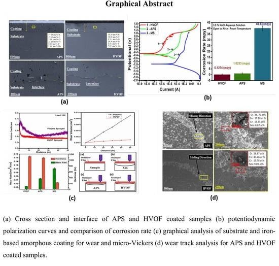
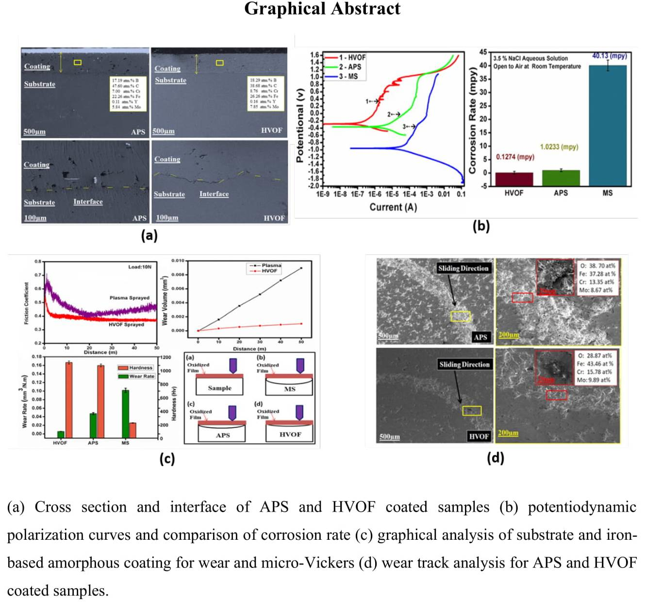
Abstract
:
1. Introduction
2. Materials and Methods
3. Results and Discussion
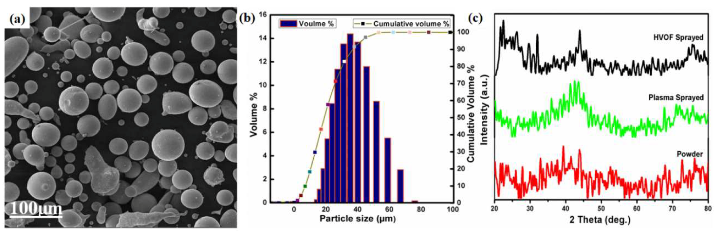
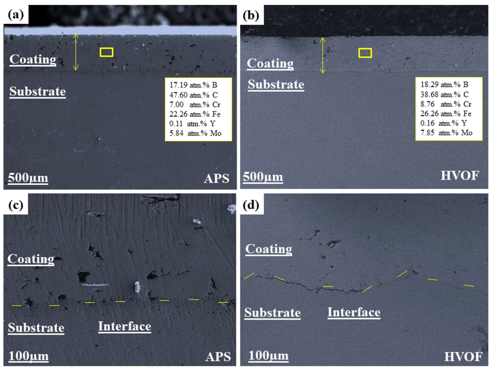
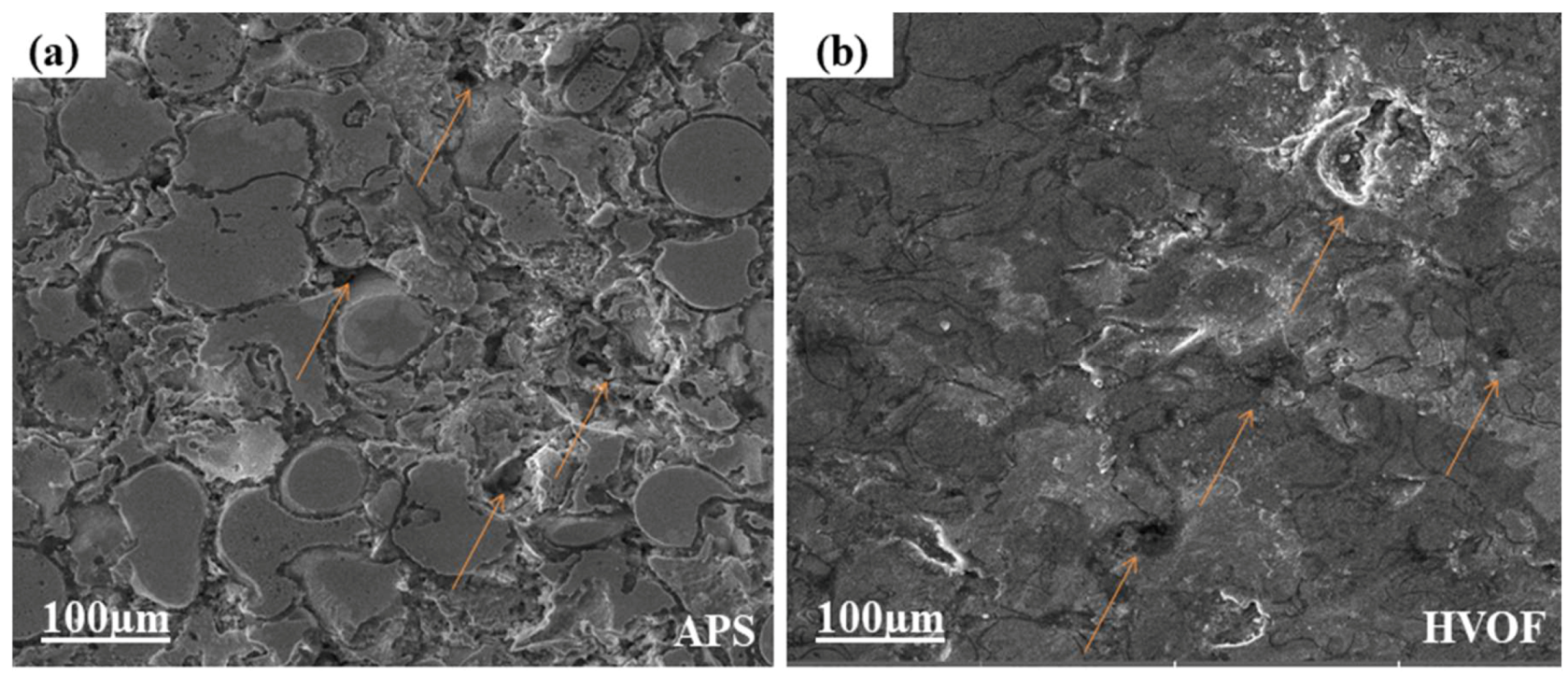
3.1. Morphological Analysis
3.2. Phase Analysis of the Coating
3.3. Corrosion Studies
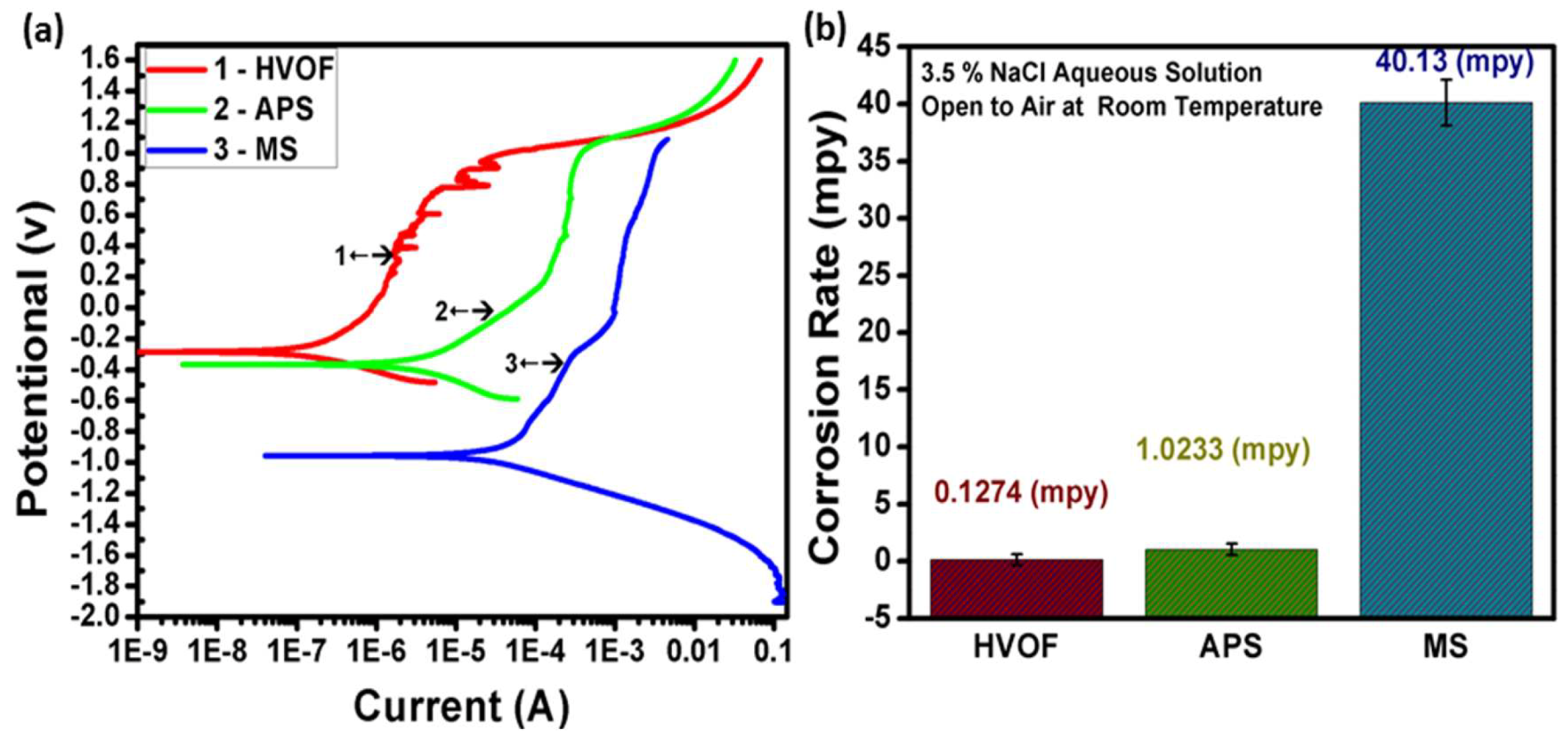
3.3.1. Potentiodynamic Polarization Scan
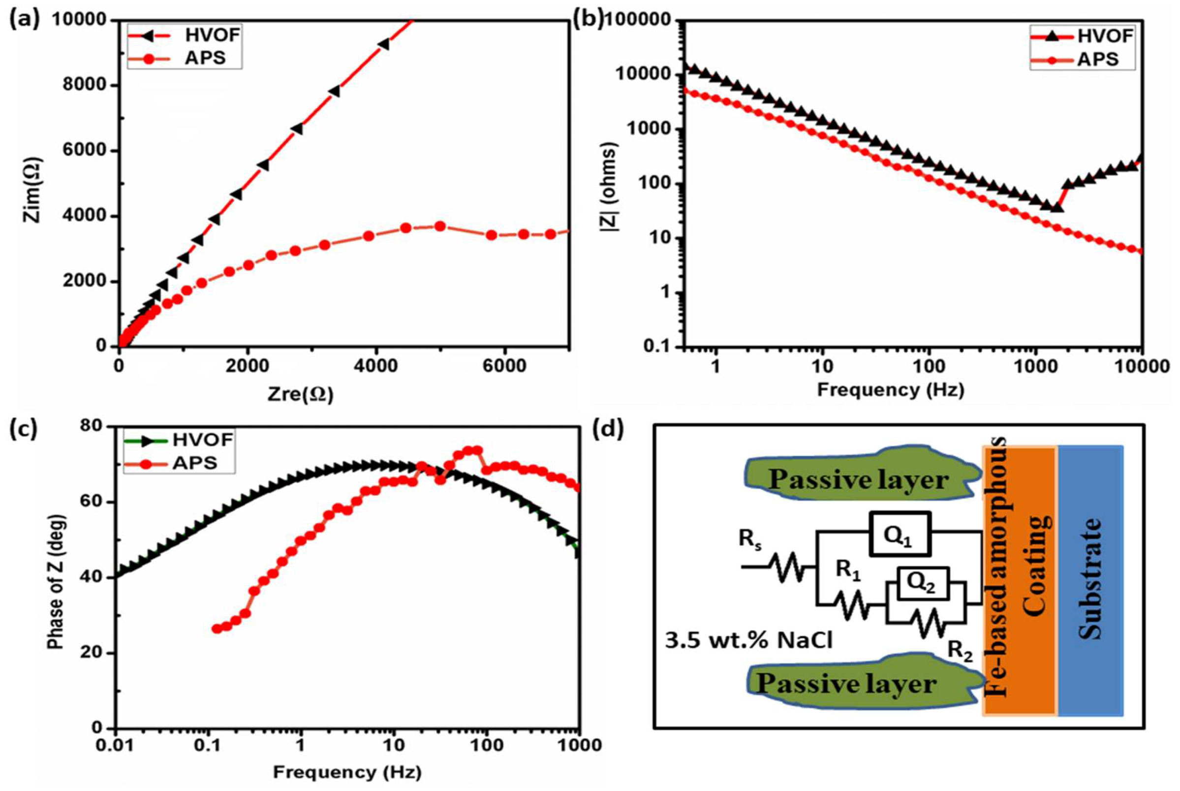
3.3.2. Electrochemical Impedance Spectroscopy
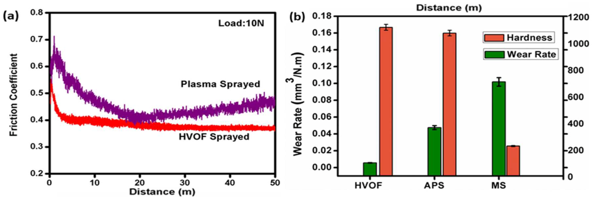
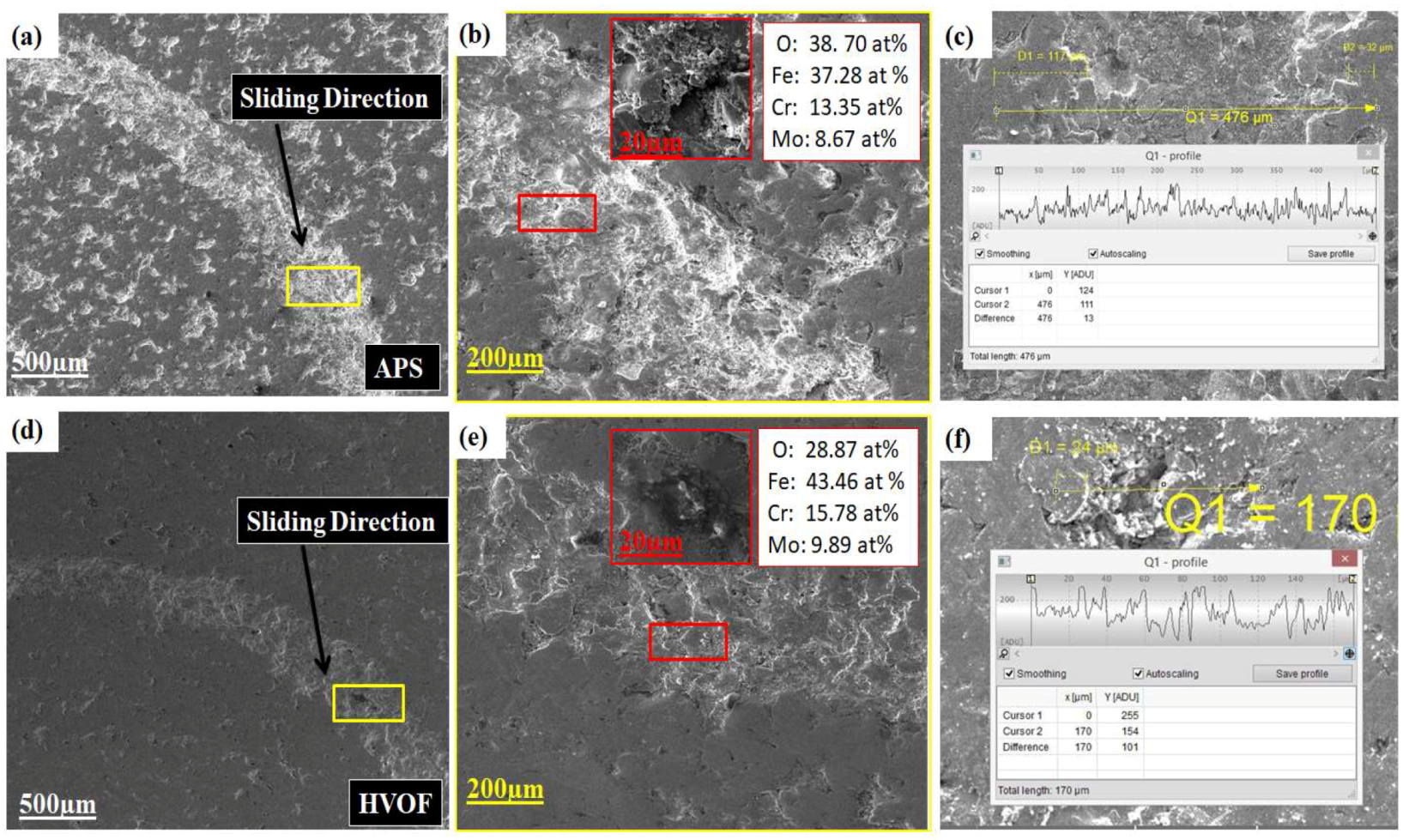
3.4. Wear Studies
Tribometric Test
4. Conclusions
Author Contributions
Funding
Conflicts of Interest
References
- Pang, S.J.; Zhang, T.; Asami, K.; Inoue, A. Synthesis of Fe-Cr-Mo-C-B-P bulk metallic glasses with high corrosion resistance. Acta Mater. 2002, 50, 489–497. [Google Scholar] [CrossRef]
- Peng, Y.; Zhang, C.; Zhou, H.; Liu, L. On the bonding strength in thermally sprayed Fe-based amorphous coatings. Surf. Coat. Technol. 2013, 218, 17–22. [Google Scholar] [CrossRef]
- Fu, B.-Y.; He, D.; Zhao, L. Effect of heat treatment on the microstructure and mechanical properties of Fe-based amorphous coatings. J. Alloy. Compd. 2009, 480, 422–427. [Google Scholar] [CrossRef]
- Zhang, C.; Liu, L.; Chan, K.C.; Chen, Q.; Tang, C.Y. Wear behavior of HVOF-sprayed Fe-based amorphous coatings. Intermetallics 2012, 29, 80–85. [Google Scholar] [CrossRef]
- Vuoristo, P. Thermal Spray Coating Processes; Elsevier: Amsterdam, The Netherlands, 2014; Volume 4, ISBN 9780080965338. [Google Scholar]
- Zhu, H.; Li, H. Microstructure Evolution of Thermally Sprayed TiB 2-Ni Cermet Coating: Comparison between APS and HVOF Process. J. Therm. Spray Technol. 2019, 28, 535–543. [Google Scholar] [CrossRef]
- Liu, L.; Zhang, C. Fe-based amorphous coatings: Structures and properties. Thin Solid Films 2014, 561, 70–86. [Google Scholar] [CrossRef]
- Huang, D.; Li, R.; Huang, L.; Ji, V.; Zhang, T. Fretting wear behavior of bulk amorphous steel. Intermetallics 2011, 19, 1385–1389. [Google Scholar] [CrossRef]
- Guo, R.Q.; Zhang, C.; Yang, Y.; Peng, Y.; Liu, L. Corrosion and wear resistance of a Fe-based amorphous coating in underground environment. Intermetallics 2012, 30, 94–99. [Google Scholar] [CrossRef]
- Qiao, L.; Wu, Y.; Hong, S.; Cheng, J.; Wei, Z. Influence of the high-velocity oxygen-fuel spray parameters on the porosity and corrosion resistance of iron-based amorphous coatings. Surf. Coat. Technol. 2019, 366, 296–302. [Google Scholar] [CrossRef]
- Kumar, A.; Nayak, S.K.; Bijalwan, P.; Dutta, M.; Banerjee, A.; Laha, T. Optimization of mechanical and corrosion properties of plasma sprayed low-chromium containing Fe-based amorphous/nanocrystalline composite coating. Surf. Coat. Technol. 2019, 370, 255–268. [Google Scholar] [CrossRef]
- Zhang, C.; Wu, Y.; Liu, L. Robust hydrophobic Fe-based amorphous coating by thermal spraying. Appl. Phys. Lett. 2012, 101, 1–5. [Google Scholar] [CrossRef]
- Li, Y.C.; Zhang, C.; Xing, W.; Guo, S.F.; Liu, L. Design of Fe-Based Bulk Metallic Glasses with Improved Wear Resistance. ACS Appl. Mater. Interfaces 2018, 10, 43144–43155. [Google Scholar] [CrossRef] [PubMed]
- Tillmann, W.; Schaak, C.; Hagen, L.; Mauer, G.; Matthäus, G. Internal Diameter Coating Processes for Bond Coat (HVOF) and Thermal Barrier Coating (APS) Systems. J. Therm. Spray Technol. 2019, 28, 233–241. [Google Scholar] [CrossRef] [Green Version]
- Fatoba, O.S.; Akinlabi, S.A.; Akinlabi, E.T.; Gharehbaghi, R. Microstructural analysis, micro-hardness and wear resistance properties of quasicrystalline Al-Cu-Fe coatings on Ti-6Al-4V alloy. Mater. Res. Express 2018, 5. [Google Scholar] [CrossRef]
- Cherigui, M.; Feraoun, H.I.; Feninehe, N.E.; Aourag, H.; Coddet, C. Structure of amorphous iron-based coatings processed by HVOF and APS thermally spraying. Mater. Chem. Phys. 2004, 85, 113–119. [Google Scholar] [CrossRef]
- Wei, Y.K.; Li, Y.J.; Zhang, Y.; Luo, X.T.; Li, C.J. Corrosion resistant nickel coating with strong adhesion on AZ31B magnesium alloy prepared by an in-situ shot-peening-assisted cold spray. Corros. Sci. 2018, 138, 105–115. [Google Scholar] [CrossRef]
- Ma, H.R.; Chen, X.Y.; Li, J.W.; Chang, C.T.; Wang, G.; Li, H.; Wang, X.M.; Li, R.W. Fe-based amorphous coating with high corrosion and wear resistance. Surf. Eng. 2017, 33, 56–62. [Google Scholar] [CrossRef]
- Lutton Cwalina, K.; Demarest, C.R.; Gerard, A.Y.; Scully, J.R. Revisiting the effects of molybdenum and tungsten alloying on corrosion behavior of nickel-chromium alloys in aqueous corrosion. Curr. Opin. Solid State Mater. Sci. 2019, 23, 129–141. [Google Scholar] [CrossRef]
- Mahata, N.; Banerjee, A.; Bijalwan, P.; Rai, P.K.; Sangal, S.; Mondal, K. Electrochemical Behavior of HVOF-Sprayed Amorphous and Nanocrystalline Fe-Based Fe73.13Si11.12B10.79Cr2.24C2.72 Composite Coatings. J. Mater. Eng. Perform. 2017, 26, 5538–5552. [Google Scholar] [CrossRef]
- Zhang, C.; Guo, R.Q.; Yang, Y.; Wu, Y.; Liu, L. Influence of the size of spraying powders on the microstructure and corrosion resistance of Fe-based amorphous coating. Electrochim. Acta 2011, 56, 6380–6388. [Google Scholar] [CrossRef]
- Yasir, M.; Zhang, C.; Wang, W.; Zhang, Z.; Liu, L. Tribocorrosion Behavior of Fe-Based Amorphous Composite Coating Reinforced by Al2O3 in 3.5% NaCl Solution. J. Therm. Spray Technol. 2016, 25, 1554–1560. [Google Scholar] [CrossRef]
- Yasir, M.; Zhang, C.; Wei, W.; Liu, P.X.L. Wear behaviors of Fe-based amorphous composite coatings reinforced by Al2O3 particles in air and in NaCl solution. Mater. Des. 2015, 88, 207–213. [Google Scholar] [CrossRef]
- Cheng, J.; Zhang, Q.; Feng, Y.; Zhao, S.; Liang, X. Microstructure and Sliding Wear Behaviors of Plasma-Sprayed Fe-Based Amorphous Coatings in 3.5 wt.% NaCl Solution. J. Therm. Spray Technol. 2019, 28, 1049–1059. [Google Scholar] [CrossRef]
- Stott, F.H.; Jordan, M.P. The effects of load and substrate hardness on the development and maintenance of wear-protective layers during sliding at elevated temperatures. Wear 2001, 250–251, 391–400. [Google Scholar] [CrossRef]
- Xie, L.; Xiong, X.; Zeng, Y.; Wang, Y. The wear properties and mechanism of detonation sprayed iron-based amorphous coating. Surf. Coat. Technol. 2019, 366, 146–155. [Google Scholar] [CrossRef]
- Wang, W.; Zhang, C.; Xu, P.; Yasir, M.; Liu, L. Enhancement of oxidation and wear resistance of Fe-based amorphous coatings by surface modification of feedstock powders. Mater. Des. 2015, 73, 35–41. [Google Scholar] [CrossRef]
- Huang, B.; Zhang, C.; Zhang, G.; Liao, H. Wear and corrosion resistant performance of thermal-sprayed Fe-based amorphous coatings: A review. Surf. Coat. Technol. 2019, 377, 124896. [Google Scholar] [CrossRef]
- Kovářík, O.; Haušild, P.; Siegl, J.; Pala, Z.; Matějíček, J.; Davydov, V. The influence of plasma sprayed multilayers of Cr2O3 and Ni10wt%Al on fatigue resistance. Surf. Coat. Technol. 2014, 251, 143–150. [Google Scholar] [CrossRef]


| Voltage | Current | Feeding Rate | Spray Distance | Power |
|---|---|---|---|---|
| 55–60 V | 200–850 A | 30 g min−1 | 200 mm | 35 KW |
| Propane Flow | Oxygen Flow | Feeding Rate | Spray Distance | Compressed Air |
|---|---|---|---|---|
| 25 L min−1 | 15 L min−1 | 30 g min−1 | 300 mm | 0.5 MPa |
| Bare and Coated Samples | Ecorr (mV) | icorr (nA/cm2) | Corrosion Rate (mpy) |
|---|---|---|---|
| APS | −364.563 mV (±0.50%) | 954.144 nA (±0.50%) | 1.0233 (±0.50%) |
| HVOF | −282.065 mV (±0.25%) | 118.793 nA (±0.25%) | 0.1274 (±0.25%) |
| Mild Steel Substrate | −0.957 V (±0.25%) | 46.7 µA (±0.25%) | 40.13 (±0.25%) |
| EIS Sample | Rs (ohm) | CPE, Yο Q1 (S-secn) | n | R1 (ohm) | CPE, Yο Q1 (S-secn) | n | R2 (ohm) |
|---|---|---|---|---|---|---|---|
| APS | 2.542 | 5.067 × 10⁻⁵ | 0.7787 | 6153 | 8.648 × 10⁻⁵ | 0.4121 | 6257 |
| HVOF | 6.389 | 0.001492 | 0.6447 | 4.335 | 8.139 × 10⁻⁷ | 0.689 | 1790 |
| Bare and Coated Samples | Coating Thickness (µm) | Hardness (Hv) | Accumulated Wear Volume (mm3) | Distance (m) | Wear Rate mm3N−1m−1 |
|---|---|---|---|---|---|
| HVOF | 302.96 | 1152 ± 22.14 | 0.001120428 | 50 | 0.005602138 (±0.000112) |
| APS | 315.98 | 1107 ± 23.04 | 0.009491135 | 50 | 0.047455677 (±0.000949) |
| MS | - | 227 ± 4.5 | 0.005092087 | 50 | 1.01842 × 10⁻⁵ (±0.00204) |
Publisher’s Note: MDPI stays neutral with regard to jurisdictional claims in published maps and institutional affiliations. |
© 2020 by the authors. Licensee MDPI, Basel, Switzerland. This article is an open access article distributed under the terms and conditions of the Creative Commons Attribution (CC BY) license (http://creativecommons.org/licenses/by/4.0/).
Share and Cite
Iqbal, A.; Siddique, S.; Maqsood, M.; Atiq Ur Rehman, M.; Yasir, M. Comparative Analysis on the Structure and Properties of Iron-Based Amorphous Coating Sprayed with the Thermal Spraying Techniques. Coatings 2020, 10, 1006. https://doi.org/10.3390/coatings10101006
Iqbal A, Siddique S, Maqsood M, Atiq Ur Rehman M, Yasir M. Comparative Analysis on the Structure and Properties of Iron-Based Amorphous Coating Sprayed with the Thermal Spraying Techniques. Coatings. 2020; 10(10):1006. https://doi.org/10.3390/coatings10101006
Chicago/Turabian StyleIqbal, Amjad, Sumera Siddique, Moazam Maqsood, Muhammad Atiq Ur Rehman, and Muhammad Yasir. 2020. "Comparative Analysis on the Structure and Properties of Iron-Based Amorphous Coating Sprayed with the Thermal Spraying Techniques" Coatings 10, no. 10: 1006. https://doi.org/10.3390/coatings10101006