
Mixed Convection of Hybrid Nanofluid in an Inclined Enclosure with a Circular Center Heater under Inclined Magnetic Field


1
Department of Quantitative Methods, College of Business Administration, Imam Abdulrahman Bin Faisal University, P.O. Box 1982, Dammam 34212, Saudi Arabia
2
Department of Mathematics and Natural Sciences, College of Sciences and Human Studies, Prince Mohammad Bin Fahd University, Khobar 31952, Saudi Arabia
3
Department of Mechanical Engineering, College of Engineering, Prince Mohammad Bin Fahd University, Khobar 31952, Saudi Arabia
*
Author to whom correspondence should be addressed.
Coatings 2021, 11(5), 506; https://doi.org/10.3390/coatings11050506
Submission received: 10 March 2021
/
Revised: 27 March 2021
/
Accepted: 7 April 2021
/
Published: 25 April 2021
(This article belongs to the Section Liquid–Fluid Coatings, Surfaces and Interfaces)
Abstract
:The hybrid nanofluids have efficient thermal networking due to the trade-off between the pros and cons of the more than one type of suspension. In the current study, water-based hybrid nanofluid is used to investigate mixed convection in a squared enclosure heated with a circular center heater. The cavity is placed inclined under the uniform inclined magnetic field. The squared cavity comprises of two adiabatic vertical walls and two cold horizontal walls. The governing equations are normalized using a suitable set of variables and are solved with the finite element method. A comparison is provided with previously reported results at limiting case. The grid independence is examined for the Nusselt number at the central heater. The analysis reveals the effective role of the concentration of hybrid nanofluid particles in enhancing the heat spread. The results indicate that adding 2% concentration of Ag-MgO hybrid nanoparticles causes an 18.3% uprise in the Nusselt number at the central heater. The heat transfer rate enhances for increasing Hartmann number between 0 and 10 but decreases over 10. For better heat transfer augmentation, a heater with a smaller radius is recommended for the free convection. In contrast, a heater with a larger radius serves the purpose in case of forced convection.
1. Introduction
Due to low thermal conductivity, the traditional heat transfer fluids like water or kerosene oil are not suitable in microelectronics and heat exchangers. It motivates researchers to create innovative fluids with significantly higher conductivities to enhance the thermal performance. The thermal conductivities of these fluids are improved by utilizing metallic or non-metallic nanoparticles in conventional fluids. There are several engineering applications where mixed convection in lid-driven cavities plays a vital role, e.g., microelectronics, chemical and drying processes, and lubrication machinery. The thermal performance is enhanced by utilizing nanofluids in a porous medium.
Mixed convection problems in enclosures and in bounded domains with moving lids can be found in numerous engineering applications, like furnaces, chemical processing equipment, lubrication technologies, microelectronics, and drying process. Several studies related to mixed convection in various cavities are available in open literature. Oztop and Dagtekin [1] investigated the mixed convection problem numerically in a square cavity and noticed powerful effects of the Richardson number on the heat transfer. Ismael, et al. [2] considered square cavity and examined the effects of volume fraction of nanoparticles on the thermal performance. Sebdani, et al. [3] examined the effects of variable thermal conductivity and viscosity on the mixed convection. They found that the rate of heat transfer depends upon pertinent parameters. Basak, et al. [4] considered different thermal boundary conditions and analyzed heat transfer to explain the variation in the Nusselt number. Abdelkhalek [5] used the perturbation method and demonstrated the crucial role of governing parameters in explaining thermal performance of the cavity.
Hasan, et al. [6] analyzed thermal performance of water-based nanofluid in the square cavity and proved the higher heat transfer rates for all conditions. Mansour, et al. [7] used different nanofluids and explored an increase in the average Nusselt number with an increase in the solid volume fraction of nanoparticles. They also reported a decrease in the average Nusselt number with an increase in the heater length. Basak, et al. [8], Alsabery, et al. [9], Li, et al. [10], and Alsabery, et al. [11] used different thermal boundary conditions and found an upsurge in the intensity of vortices with rising Grashof number. The local Nusselt number reveals non-monotonic features on the heated surface for higher Darcy and Prandtl numbers. The robust combination between flow and temperature fields has been discovered at elevated Pêclet numbers. The average heat transfer rate on the heated walls were found to be a vital function of Grashof numbers.
Cheng [12] investigated mixed convection for governing parameters. The effects of various flow parameters on the heat transfer were analyzed to develop correlations for the average Nusselt numbers in the laminar flow regimes. Later, Cheng and Liu [13] discovered that both the direction of temperature gradient and Richardson number influence the thermal performance of the cavity. Mehmood, et al. [14] and Mehmood, et al. [15] used alumina–water nanofluid and examined the effects of nonlinear thermal radiation as well as inclined magnetic field. They employed different models to analyze the effects of pertinent parameters on the thermal performance. It is noticed that the controlling parameters help in increasing the heat transfer.
Moolya and Satheesh [16] analyzed the combined effects of heat and mass transfer and noticed a rise in the Nusselt and Sherwood numbers with an increasing inclination angle. Behzadi, et al. [17] examined the impacts of the porous medium on the thermal performance in a ventilated square cavity. Using different thermal boundary conditions, they disclosed a decreasing trend of Nusselt number with a rise in the Darcy number and porous particle diameter. Garoosi, et al. [18], Garoosi and Talebi [19], and Garoosi, et al. [20] conducted numerical studies with different heating arrangements and found enhancement in the thermal performance with diminishing the nanoparticle diameter and increasing the number of the heating elements up to a certain Richardson number.
Sheremet, et al. [21] and Sheremet and Pop [22] employed Buongiorno nanofluid model and Darcy approach to study the features of water-based nanofluids. They established a rise in heat transfer with an increase in dimensionless numbers. Talebi, et al. [23] noticed that the percentage increase in the solid volume fraction of nanoparticles changes the stream pattern and thermal performance significantly at higher Rayleigh numbers. Kefayati, et al. [24] observed a rise in the heat transfer with an increase in the mixed convection parameter and reduction with increasing magnetic field. Shahi, et al. [25] discovered an improvement in the average heat transfer with increasing solid volume fraction and reduction in the average bulk temperature.
Kalteh, et al. [26] dealt with mixed convection of a water-based nanofluid and realized a substantial rise in heat transfer in the presence of the nanoparticles. Selimefendigil and Öztop [27] employed a fuzzy model to a CFD code and noticed that the fin enhances the heat transfer rate. However, thermal performance is affected by the length and inclination angle of the fin. Alsabery, et al. [28] noticed an adverse effect of nanoparticles on the heat transfer rate for larger values of mixed convection parameter and smaller Reynolds numbers. However, the nanofluid approach confirms an apparent escalation of heat transfer. Ramakrishna, et al. [29] and Ramakrishna, et al. [30] examined the impact of several boundary conditions and pertinent parameters on heat transfer rates and established that the average heat transfer rate rises with Prandtl number.
Ismael, et al. [31] imposed partial slip condition on the cavity walls and noted a decrease in heat transfer with the slip parameter. Shirvan, et al. [32] and Sourtiji, et al. [33] found a decrease in the Nusselt number with increasing magnetic field. Burgos, et al. [34] reported insignificant influence of the buoyancy force for lower Richardson numbers. Çolak, et al. [35] used Open FOAM’s software and noticed an augmentation in the Nusselt number based on chamfer radius. Further details related to current topic can be found in [36,37,38,39,40,41,42].
In the current investigation, we intend to target the combined effects of resistive magnetic force applied at an angle of attack while the square enclosure is positioned at a different angle. The square enclosure contains a circular heater and is filled with a mixture of hybrid Ag-MgO nanoparticles and water. Such effects have never been considered before despite having certain industrial applications, like, in various heat exchangers this design is used to expedite the convection. Generally, the cavity position and the magnetic field angle of inclination are not horizontal always and change with position and design, thus have significantly influence on the flow heat transfer behavior. Therefore, we think this problem should be addressed and explore to understand the square cavity problem from these aspects. The study is devoted to examining the influence of pertinent parameters, likes, Rayleigh number, Hartmann number, nanoparticles concentration, and angles of inclination on the mixed convection of hybrid nanofluids. Various graph and tables are plotted to see the variational trends and some important recommendations are made in the conclusion part.
2. Formulation of the Problem
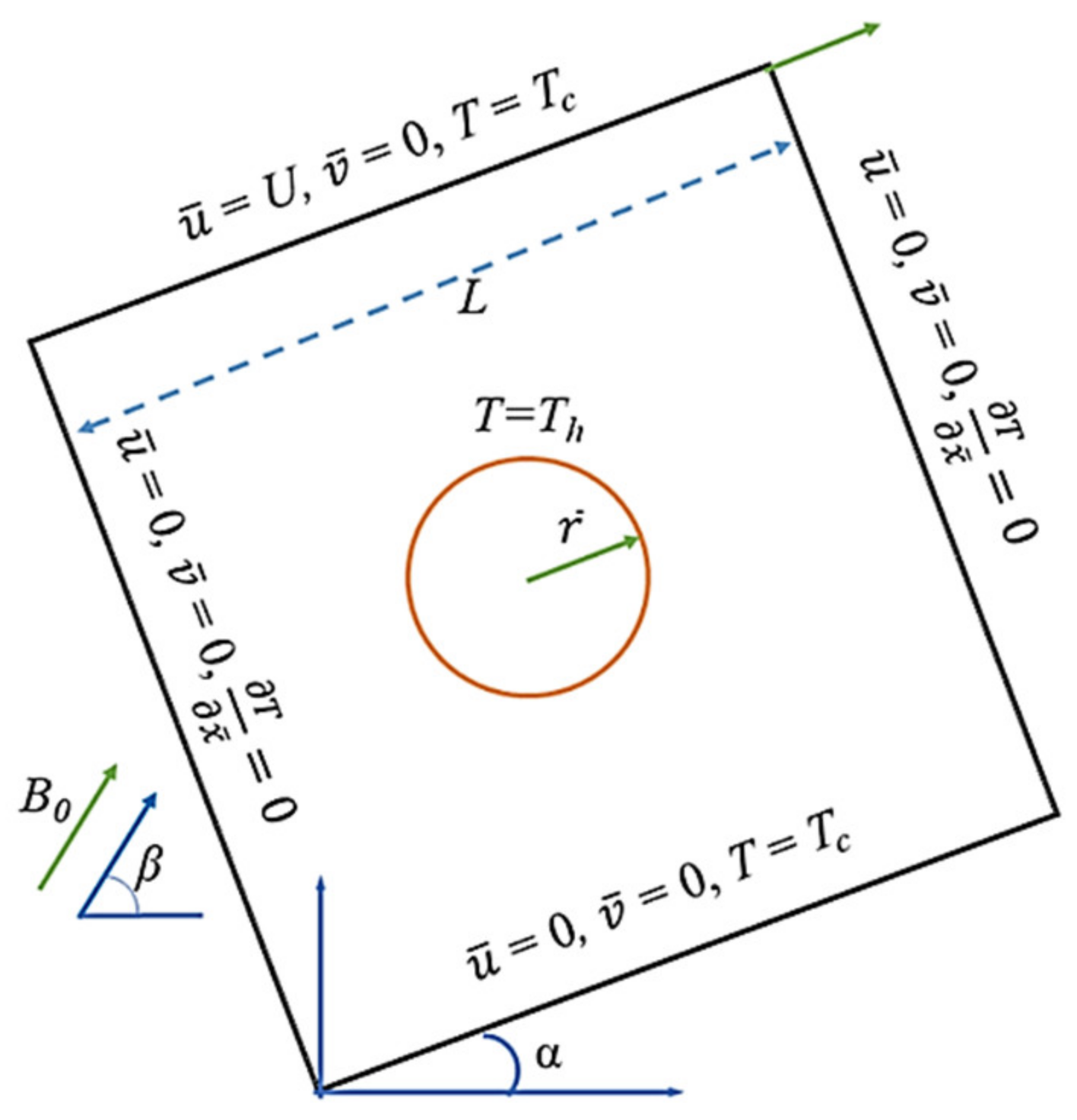
A square enclosure of dimension L is assumed to be filled with a suspension of Ag-MgO hybrid nanofluid, thoroughly dispersed in the water-based fluid. The enclosure is placed inclined at an angle α and the upper lid is moving towards right with a constant velocity U. The top and bottom boundaries are placed at a constant cooled temperature Tc while the left and right vertical boundaries are completely insulated. A circular heater of radius , situated at the center of the enclosure, is heating the enclosure with a uniform temperature Th. The base fluid and the nanoparticles are assumed to be in thermal equilibrium. The temperature differences inside the cavity are assumed to be negligible, and except density thermo-physical properties are supposed to be uniform. The Boussinesq approximation is used to model the density. Moreover, the enclosure is held under uniform Lorentz force of potency B0 in the direction of angle β. In Cartesian coordinate system the geometry of considered problem is shown in Figure 1.
The above hypotheses lead to the following set of governing equations:
The boundary data is provided in Table 1.
The hybrid nanofluid comprises of blend of water and Ag-MgO nanoparticles. Table 2 describes the thermo-physical properties of base-fluid and nanoparticles. At the reference temperature from 20 °C to 30 °C, the effective density (ρhnf) and the thermal expansion coefficient (ρβ)hnf for the hybrid nanofluid are presented by Tiwari and Das [43,44]:
and the effective heat capacity assuming thermal equilibrium is
where ϕhnf (= ϕAg + ϕMgO) is the volume fraction of hybrid nanoparticles. For effective electrical conductivity, the modified Maxwell model for hybrid nanofluids used by Ghalambaz, Sabour, Pop, and Wen [45] is assumed here and is stated as
Moreover, for thermal conductivity and dynamic viscosity, we use the model of curve fitting of experimental data by Hemmat Esfe, et al. [46]:
Invoking the following dimensionless quantities:
Employing Equation (11), the normalized form of governing Equations (1)–(4) is given by:
where the dimensionless coefficients C1, C2, C3, and C4 are constants associated with the characteristics of hybrid nanofluid and are described below as:
The local Nusselt number in normalized form at the heater and the upper wall is given by:
Hence the average Nusselt number take the following forms:
3. Numerical Solution and Validation
A numerical scheme of finite element method is applied to solve the set of nonlinear partial differential Equations (12)–(16). For this purpose, we use Newton’s linearization method to convert the nonlinear partial differential equations PDEs into linear equations. The initial seed is obtained by solving the corresponding Stokes problem. The initial seed is then employed to evaluate the linearized PDEs. The resulting linearized PDEs are solved using the NDSolve utility package of Mathematica 12. The solutions obtained are fed back into the PDEs, and the new linearized PDE is solved repeatedly until the solutions converge.
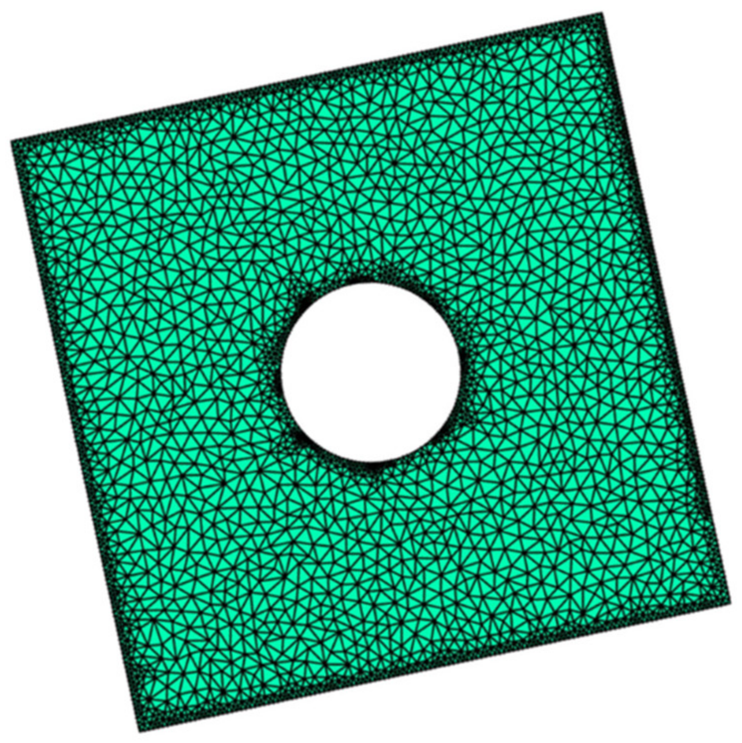
The discretization of the computational domain is created by dividing it into a finite number of non-uniform triangular elements. The smaller element size offers more accuracy but costs more computational time. Therefore, smaller element size is used near the boundaries of the computational domain so that the velocity and temperature gradients are effectively captured. However, the rest of the domain is covered with stretched elements to save computational time (refer to Figure 2 for mesh generation). Grid-independent is an essential criterion to measure the convergence of numerical results. This criterion is illustrated in Table 3 where the numerical values of average Nu are shown for looser to denser grid by increasing the number of elements. The table shows that no correction is needed up to the desired accuracy of two decimal places as the number of elements increases from 5800 elements. To save computational time, the rest of the calculations are done by fixing the mesh size at 5800 elements.
The present results are also verified by giving a comparison with a previous study by Moukalled and Acharya [47] on simple viscous fluid. The results of the current research for the limiting case are obtained by assuming the nanofluid concentration ϕhnf to be zero and considering the half-width channel with free convection. The comparison of Nuavg is provided in Table 4. The table shows well concurrence between both the studies, which validates the results reported in the present investigation and hence develops the confidence in the results presented in the coming section.
4. Results and Discussion
In this parametric study we considered the mixed convection of Ag-MgO hybrid nanofluid due to the moving lid of an inclined enclosure with the inside circular heater under inclined magnetic field. For this purpose, the radius of circle r is supposed to be fixed at 0.15, and the fluid Prandtl number Pr is kept fixed at 6.2. In further analysis, the main governing parameters, like Richardson and Hartmann numbers, angles of inclination (α and β), and the volume fraction of nanoparticles ϕhnf varies to show the discriminating characteristics of the flow phenomenon. The Richardson number (Ri = Gr/Re2) is chosen to have values of 0.01, 1 and 100 by fixing Re at 100 and varying Gr as 102, 104 and 106 so that the effect of forced, mixed and free convection could be observed. The Hartmann number Ha fluctuates from 0-100, the angles of inclination (α and β) vary from 0° to 120°, and ϕhnf takes the values between 0% and 2%.
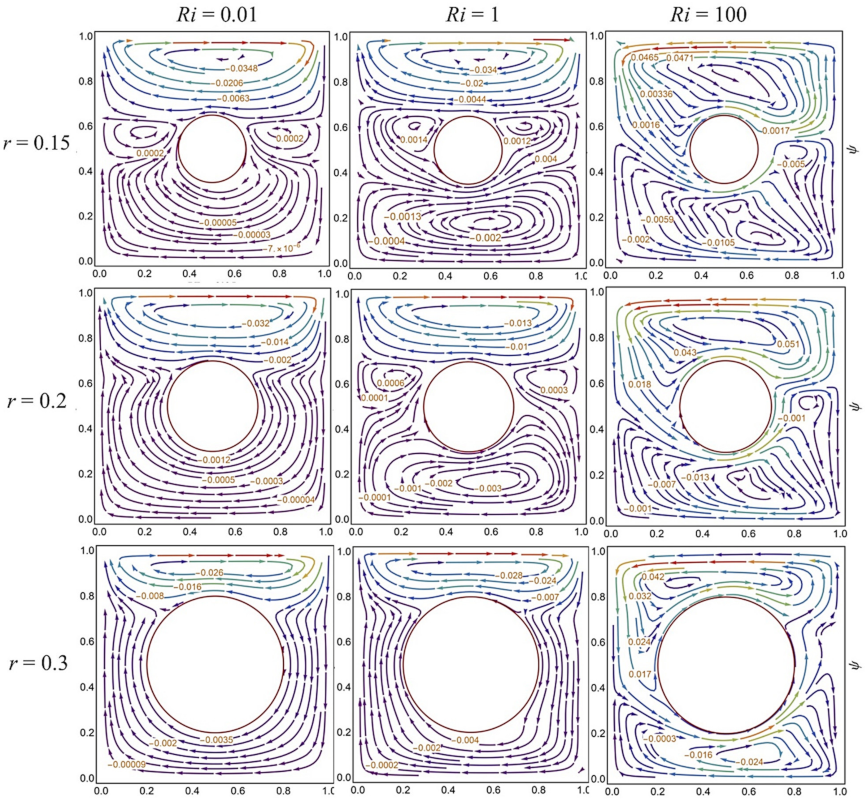
The effects of Richardson number on streamlines at different center heater radii are shown in Figure 3 while the cavity is posed at a 45° angle of inclination. The stream plots show that for forced convection case (Ri = 0.01 and r = 0.15), the enclosure is occupied by clockwise circular stream cells. At the right and left sides of the circular heater, two weak counterclockwise boluses are formed, which disappear as the radius of the heater increases to 0.2 and to 0.3. In case of mixed convection (Ri = 1), the reverse flow starts augmenting from the central part of the channel while the upper and lower parts still show the clockwise rotation in the streamlines. This reverse flow becomes weak as the radius r shifts to 0.2 and completely disappears for r = 0.3. The free convection case (Ri = 100) demonstrates the interesting feature where the counterclockwise rotation dominates the upper part of enclosure. Since the cavity is held inclined at an angle of 45°, therefore, the flow direction is toward the right side from the center heater, which is obvious conduct. The same behavior is seen for r = 0.2 and 0.3.
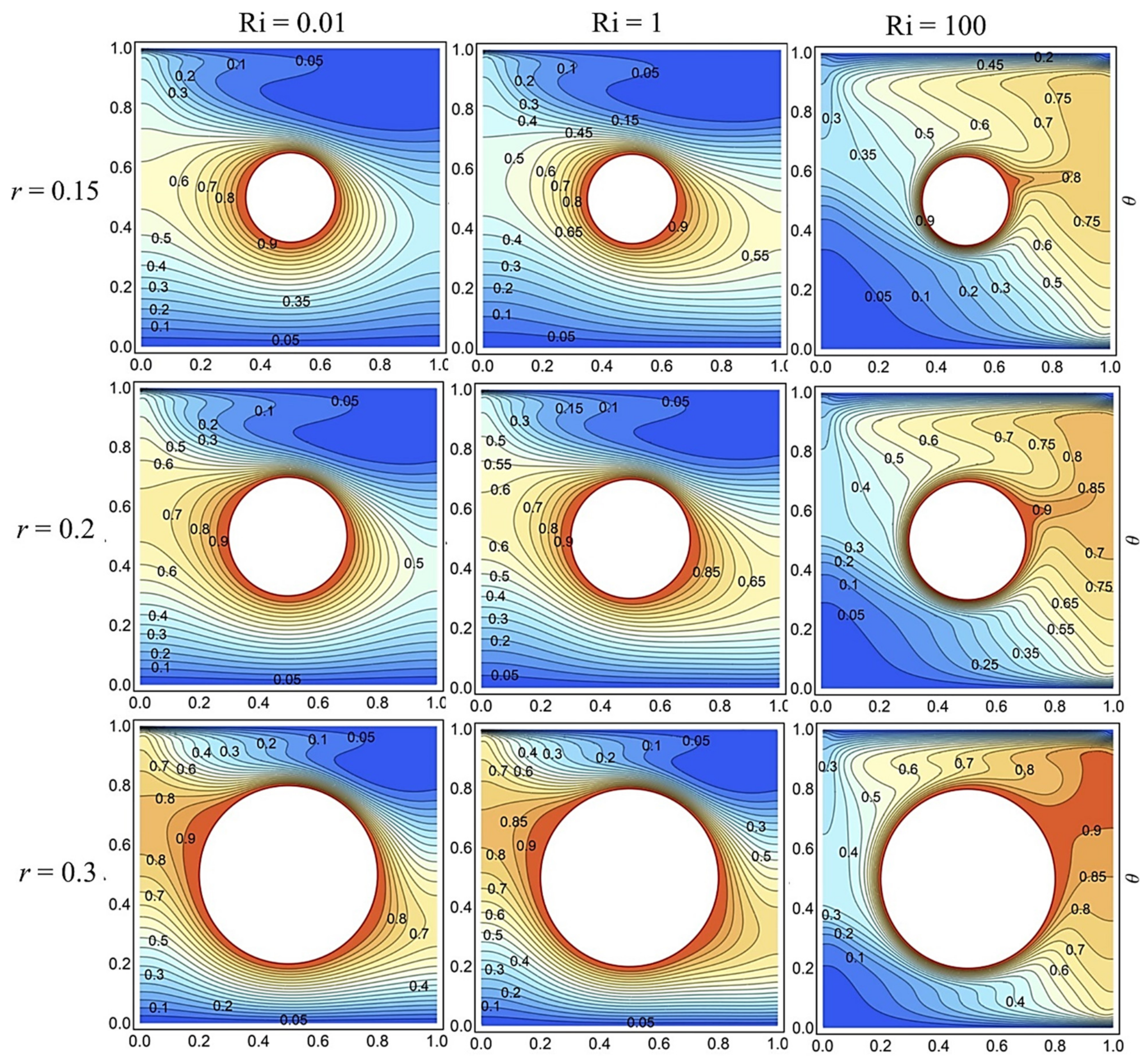
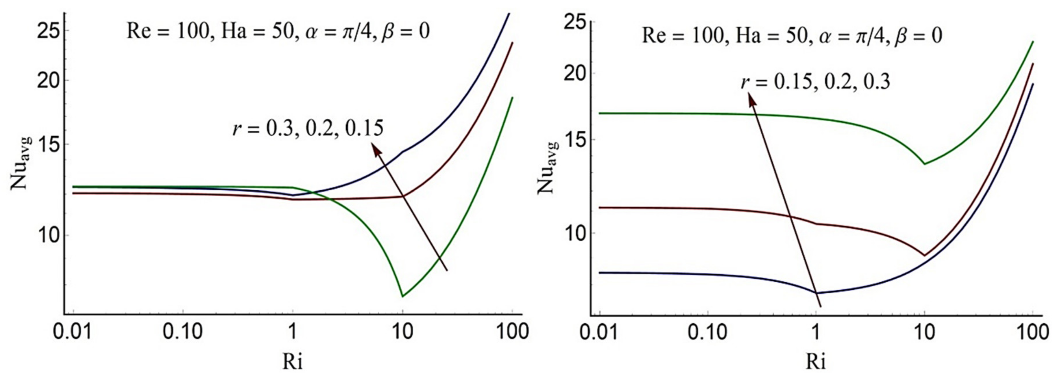
Figure 4 shows the heat lines distribution at different radii of the center heater and at various Ri values. For forced convection case, the contour lines are dispensed around the heater with heat trend toward the left side. A similar pattern of the isotherms has been noticed in the case of mixed convection cases with more shifts toward the right. However, for free convection, a clear increasing trend is noticed in temperature heading toward the right side. The thermal plum is also appeared directed towards the right wall showing the dominancy of buoyancy forces. As the radius of the center heater increases, the spread of temperature clearly rises all around in the enclosure. Figure 5 indicates that Nuavg, in case of free convection, is higher than Nuavg of forced convection. Moreover, it is found that for forced convection cases, an expansion in circle radius causes an increase in Nuavg at the central heater. However, for free convection increasing circle radius results in decreasing the Nusselt number at the central heater. Therefore, for better heat transfer augmentation heater with a smaller radius is recommended for free convection. On the other hand, for the forced convection, a heater with a larger radius serves the purpose. The Nusselt number at the upper horizontal boundary rises with an expansion in circle radius.
The streamlines and isotherm pattern are also plotted at varying α values in Figure 6, assuming mixed convection (Ri = 1). For non-inclined cavity α = 0°, the whole enclosure exhibits clockwise rotation except the lower-left corner where a weak counterclockwise recirculation cell is formed. For α = 90°, a balanced flow is observed on both sides of the center heater. However, at α = 120°, the counterclockwise recirculation becomes weak in the left part and strengthen in the right part. The contour plot of isotherms (Figure 6b) demonstrates that for the non-inclined cavity, the heat lines are stronger on the left side, and as the inclination angle rises, the temperature becomes higher on the right side leaving no significant impact in the top and bottom regions. In fact, the convection mechanism is always predominant against the gravity direction due to the buoyancy force.
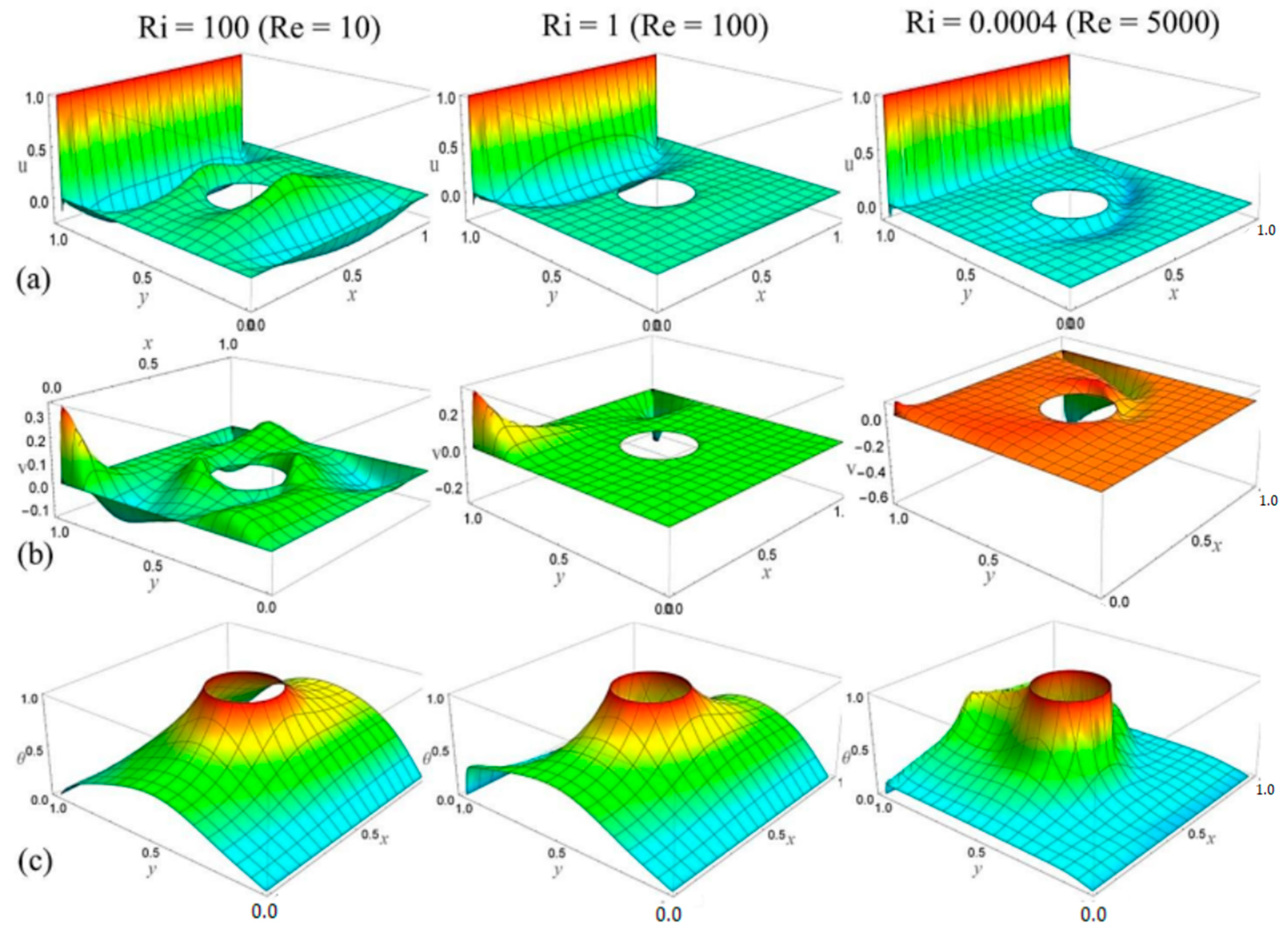
Another perspective of the convection phenomenon is to fix the parameter Gr and vary Re to observes the impact of Ri. In the present study, this viewpoint is illustrated in Figure 7, where the 3-dimensional graphs of velocity and temperature profiles are plotted by fixing Gr = 104 and varying Re from 10 to 5000, which covers the free to forced convection cases (Ri = 100, 1 and 0.01). The velocity profile u in the x-direction is plotted in Figure 7a at α = 45°. For free convection case (Ri = 100) the velocity profile satisfies the boundary condition at the upper wall and then shows a negative trend immediately below the moving plate and then attains a peak near the center heater, which indicates a counterclockwise circulation in the upper part. In the lower part, near the center heater, the velocity is positive, and near the lower surface, the velocity is negative, which indicates the formation counterclockwise circular cell. For the mixed convection case (Ri = 1), there is clear evidence of the formation of clockwise circular cells in the upper part; however, the velocity is negligible in the lower part. This is evidence of the strengthening of shear forces. For forced convection case (Ri = 0.0004), the excavation in the profile shifts to the lower side of the center heater, which indicates the predomination of the clockwise circular cell. Figure 7b presents the velocity profile v in y-direction at α = 45°. The positive values indicate the flow in the upward direction and negative values signify the downward flow. For free convection case (Ri = 100), an upward flow is noticed near the center heater, top-left, and lower-left sides of the enclosure, which is due to stronger buoyancy force. For mixed convection cases (Ri = 1), one can notice the formation of excavation in the top-right corner. The excavation becomes deeper as forced convection becomes stronger (Ri = 0.0004), which indicates a strong downward flow. In contrast, the u velocity profile is the part of the clockwise circular cell that appeared in the last part of Figure 7a. The temperature profile in Figure 7c shows the high-temperature gradient near the central heater. However, for free convection, the heat dissipates in the right side of enclosure, which is because of strong buoyancy force at elevated enclosure from the right (α = 45°). For the forced convection, the temperature gradient is stronger as compared to the free and mixed convection cases, and the heat effect accumulates around the heater and slightly dissipates in the upper part of the channel. Comparatively, the spread of heat is higher in the case of free convection as compared to the mixed and forced convection.
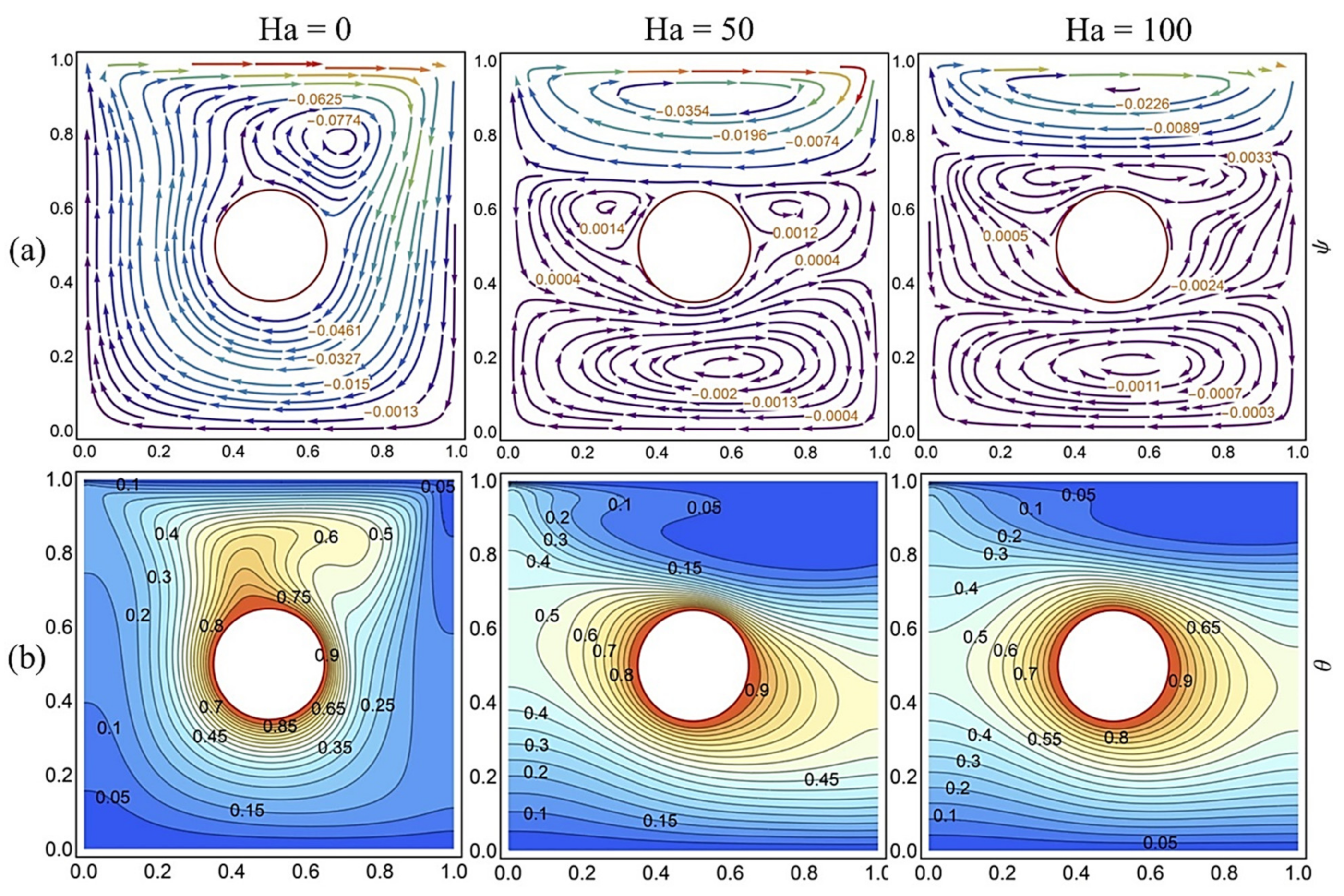
The velocity stream and heatlines are also sketched for varying magnetic field in Figure 8 assuming mixed convection Ri = 1 and inclined enclosure at α = 45°. In Figure 8a, stream plots at varying values of Ha are shown. The nonexistence of magnetic field results in the clockwise rotational cell throughout the enclosure. However, a clockwise eddy is generated along with the center heater at the upper-right edge showing a higher flow rate. As the magnetic field is introduced with Ha = 50, the flow regime is divided into three parts: the upper part, around the heater, and the lower part. The upper and lower parts demonstrate the clockwise circular boluses. However, around the circular heater, two anticlockwise eddies are formed. Overall, the flowrate inside the enclosure is reduced after the induction of the magnetic field as expected. This behavior becomes more prominent by increasing the magnetic field intensity (Ha = 100) where the anticlockwise circular eddies grow with the higher flowrate suppressing the clockwise circular cells in the upper and lower parts. This conduct is quite expected since the role of the magnetic field is to squash the flow augmentation. The isotherms contour plots are shown in Figure 8b at α = 45°. In the absence of Lorentz force (Ha = 0), the primarily spread of heat is in the upright direction. Upon introducing the Lorentz force (Ha = 50), the heat lines propagated toward the right and left sides, and this conduct of temperature becomes stronger for higher Lorentz force (Ha = 100). Consequently, the heat transport decreases around the heater (see Table 5). This behavior of temperature profile is a consequence of the reverse flow generated around the heater (see Figure 8a), which raises the convection phenomenon around the heater and lessens heat transfer rate. Table 5 shows that Nuavg at the center heater and the top wall decreases as Ha increases.
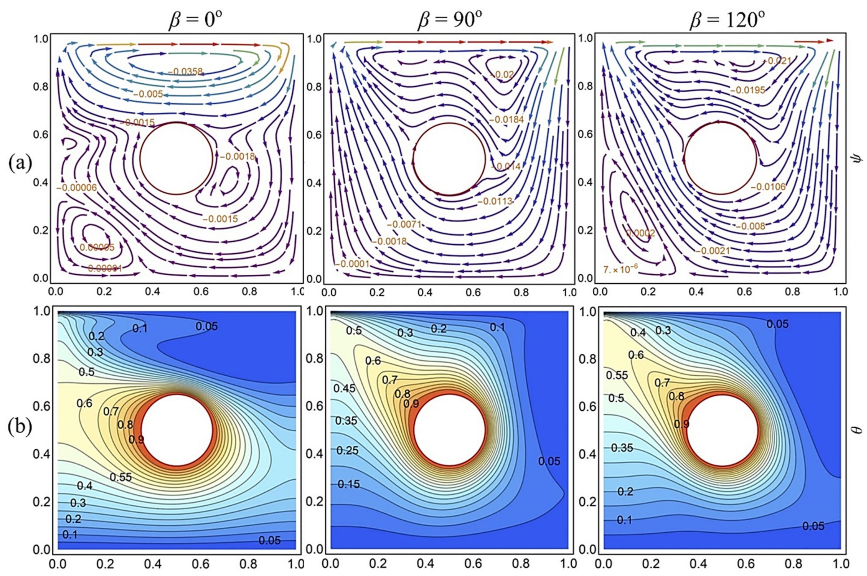
The behavior of streamlines and isotherm at varying magnetic field direction is shown in Figure 9. Figure 9a shows the streamlines plot at different inclination angles of the magnetic field for mixed convection (Ri = 1) and horizontal cavity (α = 0°). For horizontal Lorentz force (β = 0°), the streamlines plot shows two clockwise circular cells and one counterclockwise eddy in the lower-left corner with negligible circulations. For vertical Lorentz force (β = 90°), only one clockwise eddy is formed near the top wall. At β = 120°, the core upper cell slightly shifts towards the left, and a weak counterclockwise eddy is developed at the lower left side of enclosure. Overall, the flowrate is higher for the horizontal magnetic field as compared to the vertical magnetic field. The isotherms contours show that for horizontal Lorentz force, the temperature increases horizontally toward the left wall. For vertical Lorentz force, the temperature increases in the vertical direction, and the thermal plume appears toward the upper left corner. This thermal plume becomes slender for a magnetic field at an angle of 120° which leads to a higher convection rate.
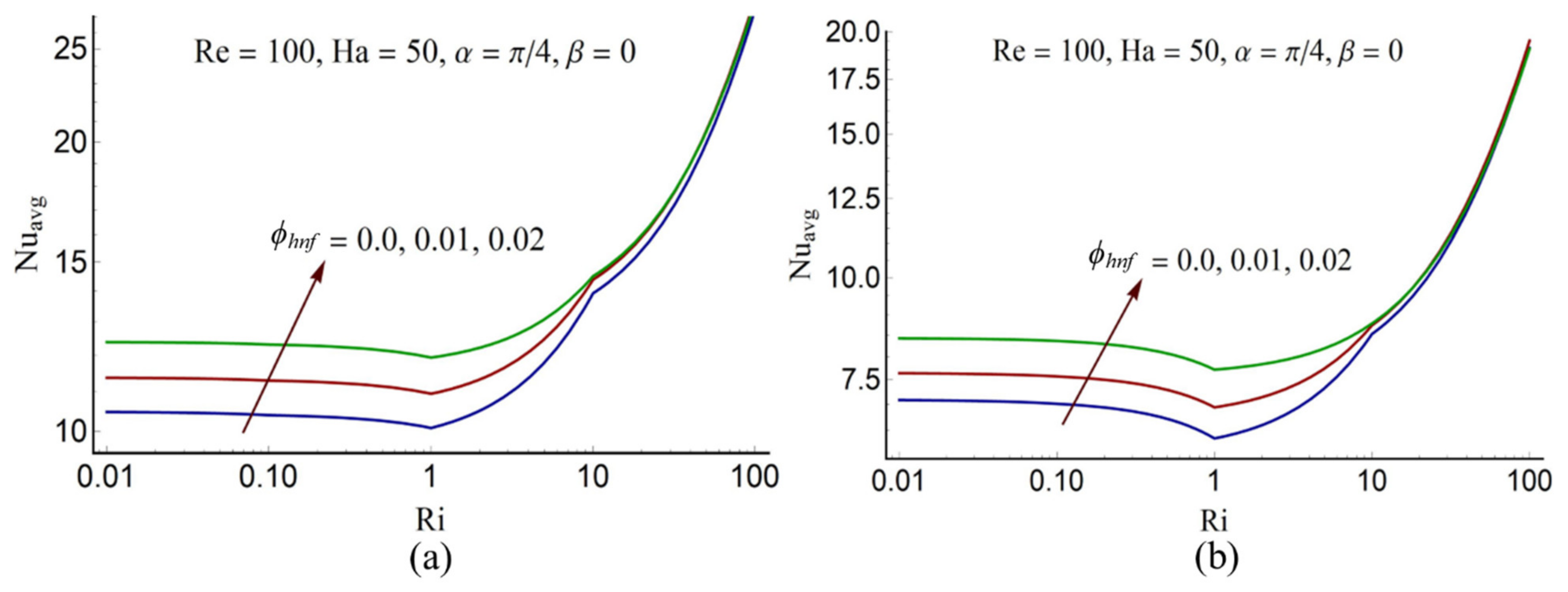
Figure 10a demonstrates an imperative behavior of the heat transfer rate at the surface of the center heater by showing the effect of parameter ϕhnf on Nuavg against Ri. The figure indicates that the convection rate reduces as Ri remains within 0.01 ≤ Ri ≤ 1. This shows that strong, forced convection increases the heat transfer rate. For Ri > 1, Nuavg increases rapidly, suggesting high heat transport in case of free convection. Moreover, the heat transfer rate significantly increases as the concentration ϕhnf increases, especially for forced convection. However, no significant change has been noticed for the free convection case as ϕhnf increases. A similar trend is noticed for Nuavg at the upper wall (see Figure 10b), though Nuavg at the upper wall is comparatively less than Nuavg at the circular heater. Such result is quite common in the study of mixed convection in cavities and reported by various authors (See for instance [9]).
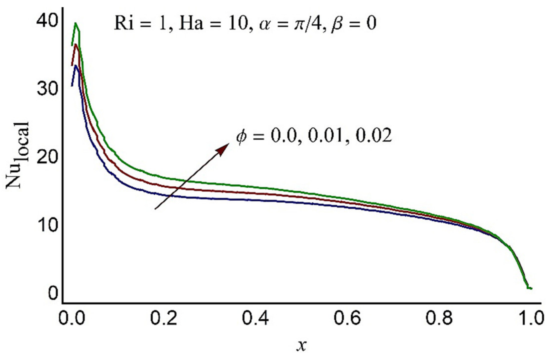
Table 4 depicts the percentage change in Nuavg as the percentage of the volume fraction of nanoparticles augments at Ri = 1. The table illustrates that by adding 1% of nanoparticles concentration results in an 8.4% increase in Nuavg at the center heater and a 9.3% increase in Nuavg at the top boundary. Introducing a 2% concentration of hybrid nanoparticles results in an increment of 18.3% and 21.6% in Nuavg at the center heater and top wall, respectively. The local Nusselt number at the upper wall is portrayed in Figure 11 for different values of volume fraction of hybrid nanoparticles for mixed convection case (Ri = 1) against the variable x. Nulocal increases as ϕhnf rises, and this rise becomes more significant at the center of the wall. As one moves toward the left side the wall Nulocal increases, and it decreases towards the right. As the wall moves toward right with uniform velocity, the clockwise circulation cell formed near the upper wall resulting in high temperature-gradient at the left side of the cold-wall, and as the particles move towards the right side, the temperature gradient decreases eventually.
5. Conclusions
We discussed a mixed convection of Ag-MgO hybrid water-based nanofluid under uniform magnetic field in a lid-driven inclined enclosure. The enclosure is heated from inside at a constant temperature by a circular heater. The top and bottom boundaries are supposed to maintain the uniform lower temperature and the side vertical walls are insulated. The numerical solutions have been presented for governing equations. A parametric analysis is made for the parameters, like, Richardson number, the Hartmann number, the concentration of hybrid nanoparticles. The important concluding remarks of the study are summarized below in points:
- The heat transport is greater in free convection as compared to the forced convection.
- It is established that for the forced convection case, an increase in circle radius results in enhancing the heat transfer rate, and for the free convection case, increasing circle radius results in decreasing the heat transfer rate.
- Overall, the circular flow rate is higher for the horizontal magnetic field in contrast to the vertical magnetic field.
- Heat transport augments as the percentage of volume fraction of hybrid nanofluid particles improve in case of forced convection but makes no significance in free convection case.
- Adding 2% concentration of hybrid nanofluid particles results in 18.3% increase in Nuavg at the center heater for mixed convection.
Author Contributions
Conceptualization, W.A.K. and S.M.; methodology, S.M.; software, S.M.; validation, S.M., N.S.; formal analysis, N.S. and S.N.; investigation, S.M.; resources, W.A.K.; data curation, S.M.; writing—original draft preparation, S.M. and W.A.K.; writing—review and editing, S.M. and W.A.K.; visualization, N.S.; supervision, N.S.; project administration, S.N.; funding acquisition, S.N. All authors have read and agreed to the published version of the manuscript.
Funding
This research received no external funding.
Institutional Review Board Statement
Not Applicable.
Informed Consent Statement
Not Applicable.
Data Availability Statement
Data is contained within the article.
Conflicts of Interest
The authors declare no conflict of interest.
Nomenclature
| Latin symbols | |
| B0 | uniform magnetic field |
| Cp | specific heat |
| Gr | Grashof number |
| Ha | Hartmann number |
| k | thermal conductivity |
| L | mensional length of cavity |
| unit normal at center circle | |
| pressure field | |
| p | dimensionless pressure |
| Pr | Prandtl number |
| radius of center circle | |
| r | dimensionless radius |
| Re | Reynolds number |
| Ri | Rayleigh number |
| S | surface of center circle |
| T | temperature field |
| Tc | temperature of cold wall |
| Th | temperature of hot wall |
| U | constant velocity of upper lid |
| velocity components | |
| (u, v) | dimensionless velocity components |
| Independent variables | |
| (x, y) | dimensionless independent variables |
| Greek symbols | |
| α | cavity angle of inclination |
| β | directional angle of magnetic field |
| ρ | density of fluid |
| (ρβ) | thermal expansion coefficient |
| σ | electrical conductivity |
| θ | dimensionless temperature field |
| μ | viscosity of fluid |
| ϕ | nanoparticles concentration |
| Subscripts | |
| hnf | hybrid nano fluid |
| f | base fluid |
| MgO | Magnesium Oxide nanoparticles |
| Ag | Silver nanoparticles |
| avg | Average |
References
- Oztop, H.F.; Dagtekin, I. Mixed convection in two-sided lid-driven differentially heated square cavity. Int. J. Heat Mass Transf. 2004, 47, 1761–1769. [Google Scholar] [CrossRef]
- Ismael, M.A.; Abu-Nada, E.; Chamkha, A.J. Mixed convection in a square cavity filled with CuO-water nanofluid heated by corner heater. Int. J. Mech. Sci. 2017, 133, 42–50. [Google Scholar] [CrossRef]
- Sebdani, S.M.; Mahmoodi, M.; Hashemi, S.M. Effect of nanofluid variable properties on mixed convection in a square cavity. Int. J. Therm. Sci. 2012, 52, 112–126. [Google Scholar] [CrossRef]
- Basak, T.; Krishna Pradeep, P.V.; Roy, S.; Pop, I. Finite element based heatline approach to study mixed convection in a porous square cavity with various wall thermal boundary conditions. Int. J. Heat Mass Transf. 2011, 54, 1706–1727. [Google Scholar] [CrossRef]
- Abdelkhalek, M.M. Mixed convection in a square cavity by a perturbation technique. Comput. Mater. Sci. 2008, 42, 212–219. [Google Scholar] [CrossRef]
- Hasan, M.N.; Samiuzzaman, K.; Haque, S.H.; Saha, S.; Islam, M.Q. Mixed Convection Heat Transfer inside a Square Cavity Filled with Cu-water Nanofluid. Proc. Eng. 2015, 105, 438–445. [Google Scholar] [CrossRef] [Green Version]
- Mansour, M.A.; Mohamed, R.A.; Abd-Elaziz, M.M.; Ahmed, S.E. Numerical simulation of mixed convection flows in a square lid-driven cavity partially heated from below using nanofluid. Int. Commun. Heat Mass Transf. 2010, 37, 1504–1512. [Google Scholar] [CrossRef]
- Basak, T.; Roy, S.; Sharma, P.K.; Pop, I. Analysis of mixed convection flows within a square cavity with uniform and non-uniform heating of bottom wall. Int. J. Therm. Sci. 2009, 48, 891–912. [Google Scholar] [CrossRef]
- Alsabery, A.I.; Ghalambaz, M.; Armaghani, T.; Chamkha, A.; Hashim, I.; Saffari Pour, M. Role of Rotating Cylinder toward Mixed Convection inside a Wavy Heated Cavity via Two-Phase Nanofluid Concept. Nanomaterials 2020, 10, 1138. [Google Scholar] [CrossRef] [PubMed]
- Li, Z.; Hussein, A.K.; Younis, O.; Afrand, M.; Feng, S. Natural convection and entropy generation of a nanofluid around a circular baffle inside an inclined square cavity under thermal radiation and magnetic field effects. Int. Commun. Heat Mass Transf. 2020, 116, 104650. [Google Scholar] [CrossRef]
- Alsabery, A.I.; Hashim, I.; Hajjar, A.; Ghalambaz, M.; Nadeem, S.; Saffari Pour, M. Entropy Generation and Natural Convection Flow of Hybrid Nanofluids in a Partially Divided Wavy Cavity Including Solid Blocks. Energies 2020, 13, 2942. [Google Scholar] [CrossRef]
- Cheng, T.S. Characteristics of mixed convection heat transfer in a lid-driven square cavity with various Richardson and Prandtl numbers. Int. J. Therm. Sci. 2011, 50, 197–205. [Google Scholar] [CrossRef]
- Cheng, T.S.; Liu, W.H. Effect of temperature gradient orientation on the characteristics of mixed convection flow in a lid-driven square cavity. Comput. Fluids 2010, 39, 965–978. [Google Scholar] [CrossRef]
- Mehmood, K.; Hussain, S.; Sagheer, M. Mixed convection in alumina-water nanofluid filled lid-driven square cavity with an isothermally heated square blockage inside with magnetic field effect: Introduction. Int. J. Heat Mass Transf. 2017, 109, 397–409. [Google Scholar] [CrossRef]
- Mehmood, K.; Hussain, S.; Sagheer, M. Numerical simulation of MHD mixed convection in alumina–water nanofluid filled square porous cavity using KKL model: Effects of non-linear thermal radiation and inclined magnetic field. J. Mol. Liq. 2017, 238, 485–498. [Google Scholar] [CrossRef]
- Moolya, S.; Satheesh, A. Role of magnetic field and cavity inclination on double diffusive mixed convection in rectangular enclosed domain. Int. Commun. Heat Mass Transf. 2020, 118, 104814. [Google Scholar] [CrossRef]
- Behzadi, T.; Shirvan, K.M.; Mirzakhanlari, S.; Sheikhrobat, A.A. Numerical Simulation on Effect of Porous Medium on Mixed Convection Heat Transfer in a Ventilated Square Cavity. Proc. Eng. 2015, 127, 221–228. [Google Scholar] [CrossRef] [Green Version]
- Garoosi, F.; Rohani, B.; Rashidi, M.M. Two-phase mixture modeling of mixed convection of nanofluids in a square cavity with internal and external heating. Powder Technol. 2015, 275, 304–321. [Google Scholar] [CrossRef]
- Garoosi, F.; Talebi, F. Numerical analysis of conjugate natural and mixed convection heat transfer of nanofluids in a square cavity using the two-phase method. Adv. Powder Technol. 2017, 28, 1668–1695. [Google Scholar] [CrossRef]
- Garoosi, F.; Bagheri, G.; Rashidi, M.M. Two phase simulation of natural convection and mixed convection of the nanofluid in a square cavity. Powder Technol. 2015, 275, 239–256. [Google Scholar] [CrossRef]
- Sheremet, M.A.; Roşca, N.C.; Roşca, A.V.; Pop, I. Mixed convection heat transfer in a square porous cavity filled with a nanofluid with suction/injection effect. Comput. Math. Appl. 2018, 76, 2665–2677. [Google Scholar] [CrossRef]
- Sheremet, M.A.; Pop, I. Mixed convection in a lid-driven square cavity filled by a nanofluid: Buongiorno’s mathematical model. Appl. Math. Comput. 2015, 266, 792–808. [Google Scholar] [CrossRef]
- Talebi, F.; Mahmoudi, A.H.; Shahi, M. Numerical study of mixed convection flows in a square lid-driven cavity utilizing nanofluid. Int. Commun. Heat Mass Transf. 2010, 37, 79–90. [Google Scholar] [CrossRef]
- Kefayati, G.R.; Gorji-Bandpy, M.; Sajjadi, H.; Ganji, D.D. Lattice Boltzmann simulation of MHD mixed convection in a lid-driven square cavity with linearly heated wall. Sci. Iran. 2012, 19, 1053–1065. [Google Scholar] [CrossRef] [Green Version]
- Shahi, M.; Mahmoudi, A.H.; Talebi, F. Numerical study of mixed convective cooling in a square cavity ventilated and partially heated from the below utilizing nanofluid. Int. Commun. Heat Mass Transf. 2010, 37, 201–213. [Google Scholar] [CrossRef]
- Kalteh, M.; Javaherdeh, K.; Azarbarzin, T. Numerical solution of nanofluid mixed convection heat transfer in a lid-driven square cavity with a triangular heat source. Powder Technol. 2014, 253, 780–788. [Google Scholar] [CrossRef]
- Selimefendigil, F.; Öztop, H.F. Fuzzy-based estimation of mixed convection heat transfer in a square cavity in the presence of an adiabatic inclined fin. Int. Commun. Heat Mass Transf. 2012, 39, 1639–1646. [Google Scholar] [CrossRef]
- Alsabery, A.I.; Ismael, M.A.; Chamkha, A.J.; Hashim, I. Mixed convection of Al2O3-water nanofluid in a double lid-driven square cavity with a solid inner insert using Buongiorno’s two-phase model. Int. J. Heat Mass Transf. 2018, 119, 939–961. [Google Scholar] [CrossRef]
- Ramakrishna, D.; Basak, T.; Roy, S.; Pop, I. Numerical study of mixed convection within porous square cavities using Bejan’s heatlines: Effects of thermal aspect ratio and thermal boundary conditions. Int. J. Heat Mass Transf. 2012, 55, 5436–5448. [Google Scholar] [CrossRef]
- Ramakrishna, D.; Basak, T.; Roy, S.; Pop, I. A complete heatline analysis on mixed convection within a square cavity: Effects of thermal boundary conditions via thermal aspect ratio. Int. J. Therm. Sci. 2012, 57, 98–111. [Google Scholar] [CrossRef]
- Ismael, M.A.; Pop, I.; Chamkha, A.J. Mixed convection in a lid-driven square cavity with partial slip. Int. J. Therm. Sci. 2014, 82, 47–61. [Google Scholar] [CrossRef]
- Shirvan, K.M.; Mamourian, M.; Mirzakhanlari, S.; Moghiman, M. Investigation on effect of magnetic field on mixed convection heat transfer in a ventilated square cavity. Proc. Eng. 2015, 127, 1181–1188. [Google Scholar] [CrossRef] [Green Version]
- Sourtiji, E.; Hosseinizadeh, S.F.; Gorji-Bandpy, M.; Ganji, D.D. Effect of water-based Al2O3 nanofluids on heat transfer and pressure drop in periodic mixed convection inside a square ventilated cavity. Int. Commun. Heat Mass Transf. 2011, 38, 1125–1134. [Google Scholar] [CrossRef]
- Burgos, J.; Cuesta, I.; Salueña, C. Numerical study of laminar mixed convection in a square open cavity. Int. J. Heat Mass Transf. 2016, 99, 599–612. [Google Scholar] [CrossRef]
- Çolak, E.; Öztop, H.F.; Ekici, Ö. MHD mixed convection in a chamfered lid-driven cavity with partial heating. Int. J. Heat Mass Transf. 2020, 156, 119901. [Google Scholar] [CrossRef]
- Islam, A.W.; Sharif, M.A.R.; Carlson, E.S. Mixed convection in a lid driven square cavity with an isothermally heated square blockage inside. Int. J. Heat Mass Transf. 2012, 55, 5244–5255. [Google Scholar] [CrossRef]
- Sourtiji, E.; Hosseinizadeh, S.F.; Gorji-Bandpy, M.; Ganji, D.D. Heat transfer enhancement of mixed convection in a square cavity with inlet and outlet ports due to oscillation of incoming flow. Int. Commun. Heat Mass Transf. 2011, 38, 806–814. [Google Scholar] [CrossRef]
- Munshi, M.J.H.; Alim, M.A.; Bhuiyan, A.H.; Ali, M. Hydrodynamic Mixed Convection in a Lid- driven Square Cavity Including Elliptic Shape Heated Block with Corner Heater. Proc. Eng. 2017, 194, 442–449. [Google Scholar] [CrossRef]
- Roy, M.; Roy, S.; Basak, T. Role of various moving walls on energy transfer rates via heat flow visualization during mixed convection in square cavities. Energy 2015, 82, 1–22. [Google Scholar] [CrossRef]
- Rashad, A.M.; Ismael, M.A.; Chamkha, A.J.; Mansour, M.A. MHD mixed convection of localized heat source/sink in a nanofluid-filled lid-driven square cavity with partial slip. J. Taiwan Inst. Chem. Eng. 2016, 68, 173–186. [Google Scholar] [CrossRef]
- Rahman, M.M.; Alim, M.A.; Sarker, M.M.A. Numerical study on the conjugate effect of joule heating and magnato-hydrodynamics mixed convection in an obstructed lid-driven square cavity. Int. Commun. Heat Mass Transf. 2010, 37, 524–534. [Google Scholar] [CrossRef]
- Chamkha, A.J.; Abu-Nada, E. Mixed convection flow in single- and double-lid driven square cavities filled with water–Al2O3 nanofluid: Effect of viscosity models. Eur. J. Mech. B/Fluids 2012, 36, 82–96. [Google Scholar] [CrossRef]
- Ma, Y.; Mohebbi, R.; Rashidi, M.M.; Yang, Z. MHD convective heat transfer of Ag-MgO/water hybrid nanofluid in a channel with active heaters and coolers. Int. J. Heat Mass Transf. 2019, 137, 714–726. [Google Scholar] [CrossRef]
- Tiwari, R.K.; Das, M.K. Heat transfer augmentation in a two-sided lid-driven differentially heated square cavity utilizing nanofluids. Int. J. Heat Mass Transf. 2007, 50, 2002–2018. [Google Scholar] [CrossRef]
- Ghalambaz, M.; Sabour, M.; Pop, I.; Wen, D. Free convection heat transfer of MgO-MWCNTs/EG hybrid nanofluid in a porous complex shaped cavity with MHD and thermal radiation effects. Int. J. Numer. Methods Heat Fluid Flow 2019, 29, 4349–4376. [Google Scholar] [CrossRef]
- Hemmat Esfe, M.; Abbasian Arani, A.A.; Rezaie, M.; Yan, W.-M.; Karimipour, A. Experimental determination of thermal conductivity and dynamic viscosity of Ag–MgO/water hybrid nanofluid. Int. Commun. Heat Mass Transf. 2015, 66, 189–195. [Google Scholar] [CrossRef]
- Moukalled, F.; Acharya, S. Natural convection in the annulus between concentric horizontal circular and square cylinders. J. Thermophys. Heat Transf. 1996, 10, 524–531. [Google Scholar] [CrossRef]
Figure 1.
Schematic diagram and the physical configuration.

Figure 2.
Mesh generation with 5362 non-uniform triangular elements.

Figure 3.
Streamlines pattern at various radii of center heater and Ri while the other parameters ϕhnf = 0.02, Ha = 50, Re = 100, α = 45°, and β = 0° are kept fixed.
Figure 3.
Streamlines pattern at various radii of center heater and Ri while the other parameters ϕhnf = 0.02, Ha = 50, Re = 100, α = 45°, and β = 0° are kept fixed.

Figure 4.
Isotherms for different Richardson number and radii of center heater while the other parameters ϕhnf = 0.02, Ha = 50, Re = 100, α = 45°, and β = 0° are kept fixed.
Figure 4.
Isotherms for different Richardson number and radii of center heater while the other parameters ϕhnf = 0.02, Ha = 50, Re = 100, α = 45°, and β = 0° are kept fixed.

Figure 5.
The average Nusselt number at different radii against Ri, (Left): At the surface of circular heater, (Right): At the top wall.
Figure 5.
The average Nusselt number at different radii against Ri, (Left): At the surface of circular heater, (Right): At the top wall.

Figure 6.
(a) Streamlines (b) Isotherms for different angle of inclination α while the other parameters ϕhnf = 0.02, Ha = 50, Ri = 1, Re = 100, r = 0.15 and β = 0° are kept fixed.
Figure 6.
(a) Streamlines (b) Isotherms for different angle of inclination α while the other parameters ϕhnf = 0.02, Ha = 50, Ri = 1, Re = 100, r = 0.15 and β = 0° are kept fixed.

Figure 7.
(a) u-velocity, (b) v-velocity, and (c) temperature profile at different Reynolds number, while the other parameters ϕhnf = 0.02, Ha = 50, Gr = 104, α = 45°, and β = 0° are kept fixed.
Figure 7.
(a) u-velocity, (b) v-velocity, and (c) temperature profile at different Reynolds number, while the other parameters ϕhnf = 0.02, Ha = 50, Gr = 104, α = 45°, and β = 0° are kept fixed.

Figure 8.
(a) Streamlines and (b) isotherms at various Ha values while the other parameters ϕhnf = 0.02, Ri = 1, α = 45, and β = 0° are kept fixed.
Figure 8.
(a) Streamlines and (b) isotherms at various Ha values while the other parameters ϕhnf = 0.02, Ri = 1, α = 45, and β = 0° are kept fixed.

Figure 9.
(a) Streamlines and (b) isotherms at various β while the other parameters ϕhnf = 0.02, Ri = 1, Re = 100, Ha = 50, α = 0° are kept fixed.
Figure 9.
(a) Streamlines and (b) isotherms at various β while the other parameters ϕhnf = 0.02, Ri = 1, Re = 100, Ha = 50, α = 0° are kept fixed.

Figure 10.
Effect of nanoparticles concentration ϕhnf on Nuavg (a) at the surface of circular heater (b) on the horizontal wall.
Figure 10.
Effect of nanoparticles concentration ϕhnf on Nuavg (a) at the surface of circular heater (b) on the horizontal wall.

Figure 11.
The local Nusselt number at the top wall for various ϕhnf against Ri.


Table 1.
The boundary data (See Figure 1 for detail).
Table 1.
The boundary data (See Figure 1 for detail).
| At the Top Wall | ||
| At the Bottom Wall | ||
| At the Left and Right Walls | ||
| At the Circular Heater |
Table 2.
The values of thermophysical characteristics of the Ag-MgO hybrid nanofluid and the base fluid Ma, et al. [43] and Ghalambaz, et al. [44].
| Physical Properties | Ag | MgO | Water |
|---|---|---|---|
| Cp (J/kg K) | 235 | 955 | 4179 |
| ρ (kg/m3) | 10,500 | 3560 | 997.1 |
| σ (S/m) | 6.3 × 10⁷ | 5.392 × 10⁻⁷ | 0.05 |
| k (W/m K) | 429 | 45 | 0.613 |
| β × 105 (1/K) | 1.89 | 1.13 | 21 |
Table 3.
Grid independency of the present solution showing Nuavg at different number of elements (Gr = 105, Re = 100, Pr = 6.2, Ha = 50, α = 45°, β = 0).
Table 3.
Grid independency of the present solution showing Nuavg at different number of elements (Gr = 105, Re = 100, Pr = 6.2, Ha = 50, α = 45°, β = 0).
| No of Elements | Nuavg at Circle | Nuavg at Top Plate |
|---|---|---|
| 900 | 14.3120 | 8.7867 |
| 2500 | 14.4136 | 8.8634 |
| 5800 | 14.5067 | 8.7763 |
| 10,000 | 14.5039 | 8.7748 |
| 17,000 | 14.5035 | 8.7747 |
| 23,000 | 14.5033 | 8.7746 |
Table 4.
Comparison of Nuavg with the results reported by Moukalled and Acharya [47] for viscous case (ϕhnf = 0) at different Rayleigh number and radius.
Table 4.
Comparison of Nuavg with the results reported by Moukalled and Acharya [47] for viscous case (ϕhnf = 0) at different Rayleigh number and radius.
| Ra | r = 0.1 by [47] | r = 0.1 Present | r = 0.2 by [47] | r = 0.2 Present | r = 0.3 by [47] | r = 0.3 Present |
|---|---|---|---|---|---|---|
| 0 | 1.836 | 1.863 | 3.26 | 3.166 | 5.369 | 5.358 |
| 104 | 2.071 | 2.069 | 3.331 | 3.225 | 5.826 | 5.373 |
| 105 | 3.825 | 3.773 | 5.08 | 4.909 | 6.212 | 6.214 |
| 106 | 6.107 | 6.102 | 9.374 | 8.901 | 11.62 | 10.293 |
Table 5.
The numerical values of Nuavg at the center heater and at the top wall Re = 100, Ri =1.
| Ri | ϕhnf | α | Ha | β | Nuavg at Circle | Nuavg at Top Plate |
|---|---|---|---|---|---|---|
| 1 | 0.00 | 45° | 50 | 0° | 10.09 (0.0%) | 6.35 (0.0%) |
| - | 0.01 | - | - | - | 10.94 (8.4%) | 6.94 (9.3%) |
| - | 0.015 | - | - | - | 11.55 (14.5%) | 7.43 (17.0%) |
| - | 0.02 | - | - | - | 11.94 (18.3%) | 7.72 (21.6%) |
| 1 | 0.02 | 30° | 10 | 0 | 17.68 | 15.33 |
| - | - | 60° | - | - | 17.09 | 14.62 |
| - | - | 90° | - | - | 17.30 | 14.82 |
| - | - | 120° | - | - | 15.67 | 11.45 |
| 1 | 0.02 | 45° | 0 | 0° | 14.48 | 11.51 |
| - | - | - | 10 | - | 17.31 | 14.88 |
| - | - | - | 25 | - | 15.91 | 14.22 |
| - | - | - | 50 | - | 11.94 | 7.72 |
| - | - | - | 100 | - | 9.48 | 5.47 |
| 1 | 0.02 | 45° | 10 | 0° | 18.60 | 16.47 |
| - | - | - | - | 30° | 18.16 | 15.92 |
| - | - | - | - | 60° | 17.57 | 15.23 |
| - | - | - | - | 90° | 17.48 | 15.16 |
| - | - | - | - | 120° | 17.93 | 15.72 |
Publisher’s Note: MDPI stays neutral with regard to jurisdictional claims in published maps and institutional affiliations. |
© 2021 by the authors. Licensee MDPI, Basel, Switzerland. This article is an open access article distributed under the terms and conditions of the Creative Commons Attribution (CC BY) license (https://creativecommons.org/licenses/by/4.0/).
Share and Cite
MDPI and ACS Style
Munawar, S.; Saleem, N.; Ahmad Khan, W.; Nasir, S. Mixed Convection of Hybrid Nanofluid in an Inclined Enclosure with a Circular Center Heater under Inclined Magnetic Field. Coatings 2021, 11, 506. https://doi.org/10.3390/coatings11050506
AMA Style
Munawar S, Saleem N, Ahmad Khan W, Nasir S. Mixed Convection of Hybrid Nanofluid in an Inclined Enclosure with a Circular Center Heater under Inclined Magnetic Field. Coatings. 2021; 11(5):506. https://doi.org/10.3390/coatings11050506
Chicago/Turabian StyleMunawar, Sufian, Najma Saleem, Waqar Ahmad Khan, and Sumiya Nasir. 2021. "Mixed Convection of Hybrid Nanofluid in an Inclined Enclosure with a Circular Center Heater under Inclined Magnetic Field" Coatings 11, no. 5: 506. https://doi.org/10.3390/coatings11050506
Note that from the first issue of 2016, this journal uses article numbers instead of page numbers. See further details here.