
Twisting Structures in Liquid Crystal Polarization Gratings and Lenses
by
Shiyuan Zhang
1,2, 
Wan Chen
1,2,
Yang Yu
1,2,
Qidong Wang
1,*,
Quanquan Mu
1,2,*,
Shixiao Li
1,2 and
Jin Chen
1,2 1
Changchun Institute of Optics, Fine Mechanics and Physics, Chinese Academy of Sciences, Changchun 130033, China
2
Center of Material Science and Optoelectronics Engineering, University of Chinese Academy of Sciences, Beijing 100049, China
*
Authors to whom correspondence should be addressed.
Crystals 2021, 11(3), 243; https://doi.org/10.3390/cryst11030243
Submission received: 31 January 2021
/
Revised: 23 February 2021
/
Accepted: 24 February 2021
/
Published: 27 February 2021
(This article belongs to the Special Issue Liquid-Crystal Polarization Gratings)
Abstract
:Recently, diverse twisting structures have been discovered to be a potential approach to design liquid crystal polarization gratings and lenses (LCPGs and LCPLs) with a high diffraction efficiency, broad bandwidth, wide view, and large diffraction angle. In this review, we divide these twisting structures into two main types, namely, multi-layer twisting structures with phase compensation and twisting structures forming Bragg diffraction. We found that multi-layer twisting structure LCPGs and LCPLs presented a broader bandwidth and a wider view angle by phase compensation. While for transmissive or reflective Bragg LCPGs, a large diffraction angle with high diffraction efficiency could be achieved. Based on the theoretical analysis in the review, potential research directions on novel twisting structures were prospected.

1. Introduction
Since the geometrical phase [1,2,3] was proposed in 1956, a new degree of freedom was provided to modulate the phase, amplitude, polarization and wave front of light waves. Many kinds of geometrical phase devices have been discovered and researched over the years. Liquid crystal (LC) based devices, such as liquid crystal polarization gratings and lenses (LCPGs and LCPLs), were one of the most important types due to their excellent performance for various applications, like non-mechanical beam deflection [4,5,6], virtual/augmented reality (VR/AR) display, near-eye display and waveguide-based display devices [7,8,9,10,11,12,13,14], etc.
From the previous studies [4,5,15,16,17], LCPGs and LCPLs with typical planar structure can include 100% diffraction into a single order. However, the diffraction efficiency equations are derived using the paraxial approximation, which means the devices are considered “thin” [18,19,20]. Thus, a diffraction efficiency of 100% can only be achieved at a specific wavelength, which meets the half wave condition (Δnd/λ = (2k + 1)/2, where k is an integer). Therefore, if it deviates from the design wavelength, the diffraction efficiency of the device will decrease rapidly. Besides, for LCPGs, a large diffraction angle could be achieved by decreasing its period Λ. However, for a small-period LCPG (usually, Λ < 2 μm [18,21]), which no longer meets the condition of a “thin” grating, its diffraction efficiency falls sharply. The above restrictions would seriously affect practical applications, such as near-eye and full-color displays [10], which need a large diffraction angle.
In order to solve the problems above, several in-depth studies have been developed. Combining the self-organized structure and optical properties of twisted liquid crystals with the traditional PGs and PLs is the main research direction at present. Based on phase compensation, Oh et al. [19,22,23] have proved that the dual-twist structure can broaden the bandwidth of high diffraction efficiency, and Li Tan [15,24,25] has also confirmed that a twisting structure can also provide certain compensation in terms of view angle. Tao Zhan [11,14], Lingshan Li [26] et al. studied wide-band lens. Under certain conditions, a Bragg diffraction could be achieved by a twisting structure. Xiao Xiang et al. [27,28,29,30] introduced transmissive Bragg PGs based on single and dual-layer twisting structures with large diffraction angles. Yishi Weng et al. [7,9,10] studied Bragg gratings and reflective polarized volume gratings (PVGs) with high efficiency and large diffraction angle. Kun Yin [13,14] and Li et al. [12] studied polarized volume lens (PVLs). These reflective devices can be applied in various fields like wearable displays. From those works reported above, we found that the twisting structures, which work in different methods [7,14], are well used by researchers to produce a series of devices with better performance.
In this work, we review recent advances of LCPGs and LCPLs with twisting structure. First in Section 2, we begin with the LC director configuration and optical properties of the twisted liquid crystals. Then we delve into the theoretical model and the differences between various kinds of gratings and lenses. In Section 3, we discuss LCPGs and LCPLs with multi-layer twisting structures, which provide a better performance in terms of broadband and wideview angle. In Section 4, we focus on Bragg diffraction LCPGs and LCPLs with high efficiency, large-angle diffraction generated by twisting structures. Then, several kinds of reflective and transmissive devices are expounded.
2. Twisted LC with LCPG Structure
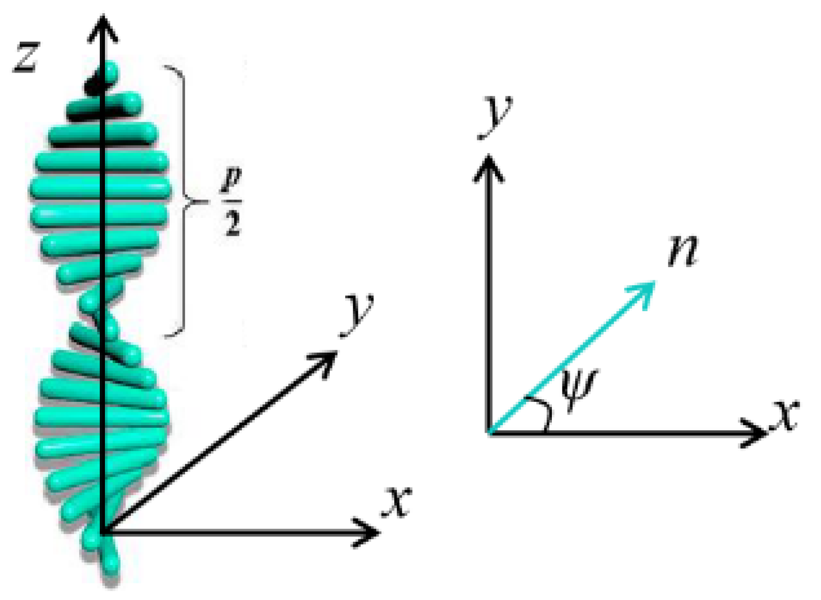
Figure 1 illustrates the twisting structure of LC. Note that the LC is still in a nematic phase in each plane (x-y plane) perpendicular to the helical axis (z axis), which could be regarded as a uniaxial crystal.
Equation (1) represents the LC director field:
where ψ is the azimuth angle at z, φ0 is the azimuth angle of the initial position (z = 0). The helical pitch P was defined as the distance in which the orientation of LC molecules rotated 360 degrees. The direction of the twist is represented by the sign of the helical pitch P, usually the right-handed twisting is defined as positive (P > 0).
According to the relationship between the wavelength and the helical pitch, the optical property of the LC layer could be divided into four different regions [31]:
- Mauguin region: In this region (λ << 0.5ΔnP), the polarization ellipses of the eigenmodes have either near-infinite ellipticity with the long axis parallel or perpendicular to the local director, which could be approximated as a pair of orthogonal linear polarization states. As the eigenmodes propagate in the medium, the polarization axes will follow the twist of the local director, which is called waveguiding (or adiabatic following). TN-LCDs correspond to this situation [32];
- Short-wavelength circular birefringence region (SW-CBR): In this region (λ < P), the eigenmodes are elliptically polarized with the opposite handedness. As helical pitch decreases, the waveguiding phenomenon no longer holds. When the incident polarized light propagates in the LC layer, its polarization axis still rotates, but, usually, it will not remain parallel (or perpendicular) to the local LC director. Besides, its ellipticity will change along with the propagation distance. In essence, the Mauguin region is a limiting case of this region;
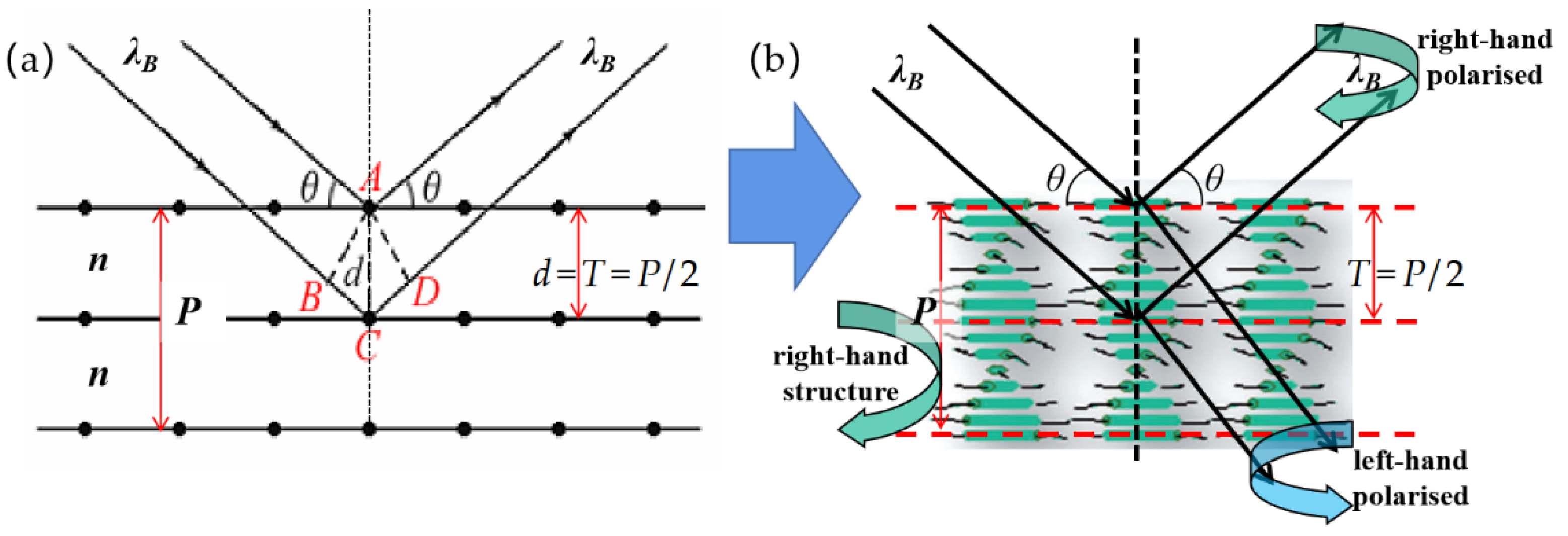
- Bragg region: In this region (noP < λ < neP), the liquid crystal layer will provide a strong selective circular reflection to the incident light, that is, a circular polarized incident light with the same rotation direction of the LC layer will be reflected, meanwhile the opposite one could propagate through. The twisting LC configuration produces a Bragg structure: its period T (T = 0.5P) could be regarded as a series of the crystal plane, shown in Figure 2. According to Equation (2), which is known as Bragg’s law:supposed that the medium within a period is homogeneous and provides an average refractive index , θ is the angle between the incident light and the “crystal plane”. For normal incidence (θ = 90°), the central wavelength of the reflection is , and the reflectance band is noP < λ < neP. For tilted incidence, the central wavelength of the reflection is .
- Long-wavelength circular birefringence region (LW-CBR): In this region (λ >> P), both eigenmodes are almost circularly polarized, and would pass through the LC layer. However, due to the difference in the wavenumber (refractive index), their propagation speeds are different, and the principal axes of their resultant, a beam of linearly polarized light, has a net rotation relative to the LC director at the exit plane.
It is necessary for us to know well the optical properties of twisting liquid crystals, which could help us to understand the reasons why polarization gratings in such structures could present different effects. Furthermore, it would provide theoretical guidance and new ideas for the research of a new generation of high-performance LC devices.
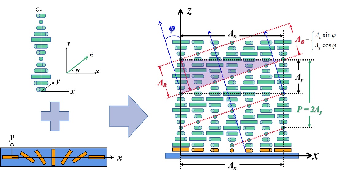
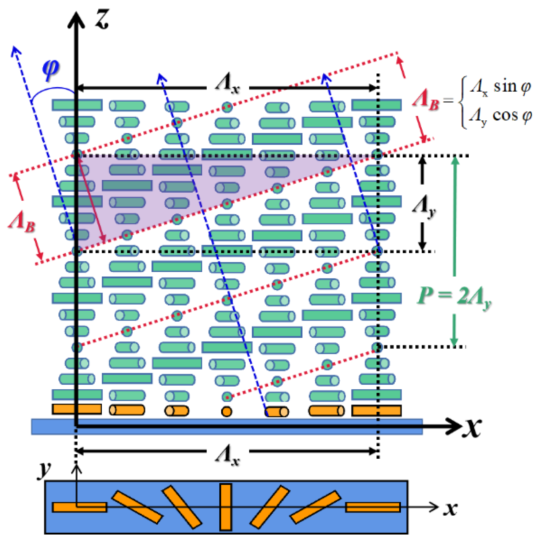
Based on the optical characteristics of the twisted liquid crystals mentioned above, combining the periodic structure Λx in the horizontal plane introduced by the typical planar LCPG alignment surface and Λy = P/2 along the vertical direction introduced by twisted LC, a series of slanted and periodical refractive index planes [7] have been set up, as shown by the red dashed line in Figure 3. The slant angle is φ = ± arctan (Λy/Λx), (0° < φ < 90°).
These refractive index surfaces constitute a periodicity ΛB:
in a slanted dimension and, by different given ΛB values, the diffraction behavior of the grating changes obviously:
- Bragg diffraction can be established when ΛB meets the condition of the incident wavelength, according to Equation (2) (where d = ΛB, θ = π/2 − φ) and LC layer is thick enough to generate enough periodical refractive index planes. Then a large-angle diffraction with high efficiency can be achieved [7,28,30,33].
- When the pitch ΛB is much greater than that in the Bragg condition, the optical properties of the twisted LC itself (in short-wave circular birefringence region) is revealed. It has a potential to create a LCPG or LCPL with broadband and wide-view angle [22,23,26,34,35], by means of phase compensation.
We will discuss these two situations in detail separately below by reviewing recent research.
3. Broadband and Wide-View Angle LCPGs and LCPLs—Based on Phase Compensation of Multi-Layer Twisted LC Structures
In most applications, PB phase optical devices with broad bandwidth, wide-view angle, and high diffraction efficiency, are highly desirable. There are some well-known techniques to implement achromatic waveplates [36,37,38,39], which can be employed in PB phase optical devices. Note that broadband polarization transformation could be achieved through additional degrees of freedom arising from using multiple uniaxial retarders, whose optical axis varies discretely through the compound structure.
The multi-uniaxial-layer design could also be extended to birefringent layers with a continuously varying optical axis. For example, the self-compensation of retardation is done using self-aligning multi-twist structures (2013, Komanduri et al. [38]). During the layer-by-layer spin coating process, subsequent LC layers are directly aligned with previous ones. This process has greatly simplified fabrication, and reduced transmittance loss and alignment errors. By using chiral-doped LC materials, retardation control for nearly arbitrary bandwidths could be achieved. Besides, we can also control the thickness of each layer by spin-coating to avoid the deterioration of LC alignment and device quality caused by exceeding the critical thickness [40].
3.1. Dual-Layer Twisted PGs with Broadband and Wide-View Angle
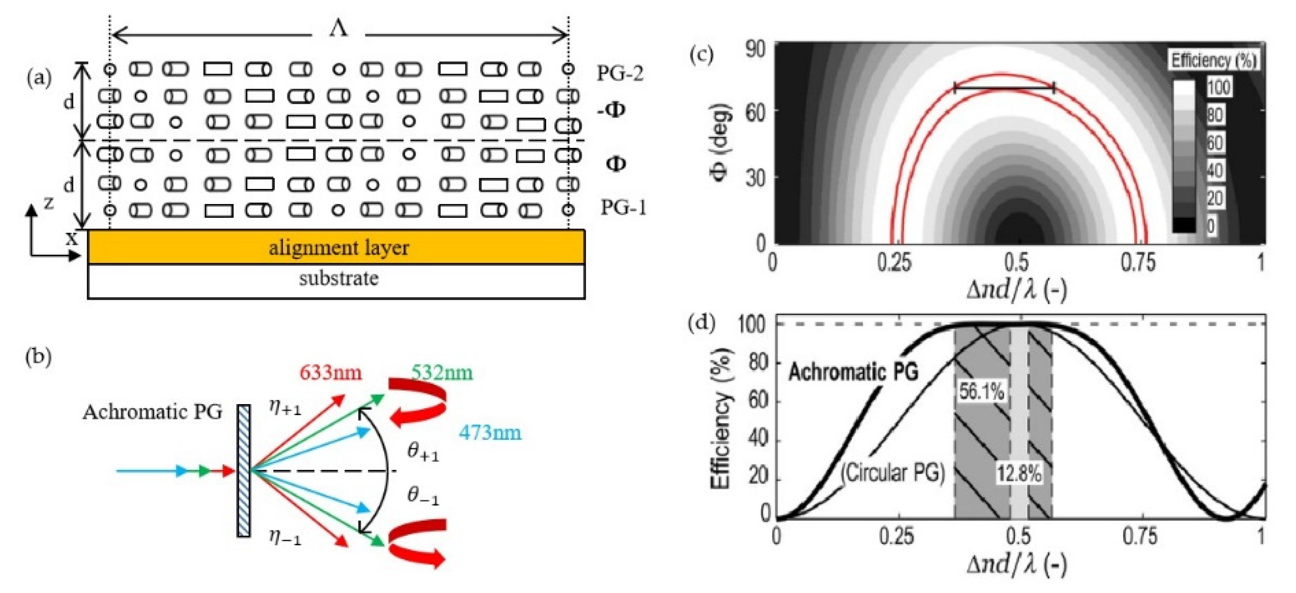
Based on the principle of phase compensation, Oh et al. [19,22,23]. studied and fabricated a wide-band LCPG (or achromatic PG) by using a double-layer low-twisted structure with opposite twist direction illustrated in Figure 4a,b. The results show that the PG has high diffraction efficiency in a broadband (Figure 4c) by using extended Jones matrix analysis (EJM) and the finite difference time domain (FDTD) method. Compared with the traditional LCPG (or circular PG), the high diffraction bandwidth is increased by five times (Figure 4d). The bandwidth would increase gradually with the increase of the twist angle Φ for the twist angles less than 70°. Besides, the bandwidth would decrease sharply with the increase in twist angle for a condition with a twist greater than 70°. The achromatic behavior can be explained by the counter chromatic dispersions of retardation caused by linear birefringence and induced circular birefringence due to twist [31]. The former birefringence becomes larger in the short-wavelength band while the latter becomes larger in the long-wavelength band. When the thickness of the LC layer reaches the halfwave condition with the 70° twist angle, the achromatic diffraction is achieved by balancing these two effects for phase compensation.
In the case of oblique incidence, the diffraction efficiency of the primary type of PG will be sharply reduced [20]. Tan Li et al. [15,24,25] simulated the diffraction characteristics of oblique incidence by using the extended Jones matrix (EJM) method and optimized a dual-layer PG with wide viewing angle (WVA). An example [15] was given: a WVA PG, Λ = 2 μm, Δnd/λ = 0.61, and a primary PG with the same Λ, Δnd/λ = 0.5. Results showed that, at an incident angle of 20°, the dual-layer PG maintains a high diffraction efficiency of 99.5% at 550 nm, while the primary PG has a 0th order leakage of 10%.
Note that a WVA PG requires a special optimization and the feature of broadband disappeared in their design. That is to say, it is difficult for a dual-layer PG to achieve two good features at the same time. More studies on angular response using numerical models like FDTD [22], and rigorous coupled wave analysis (RCWA) method [41], etc., have been proposed by Oh, Xiang Xiao et al., and will not be detailed in this review.
3.2. Three-Layer Multi-Twist PGs and PLs with Ultra-Broadband and Wide-View Angle
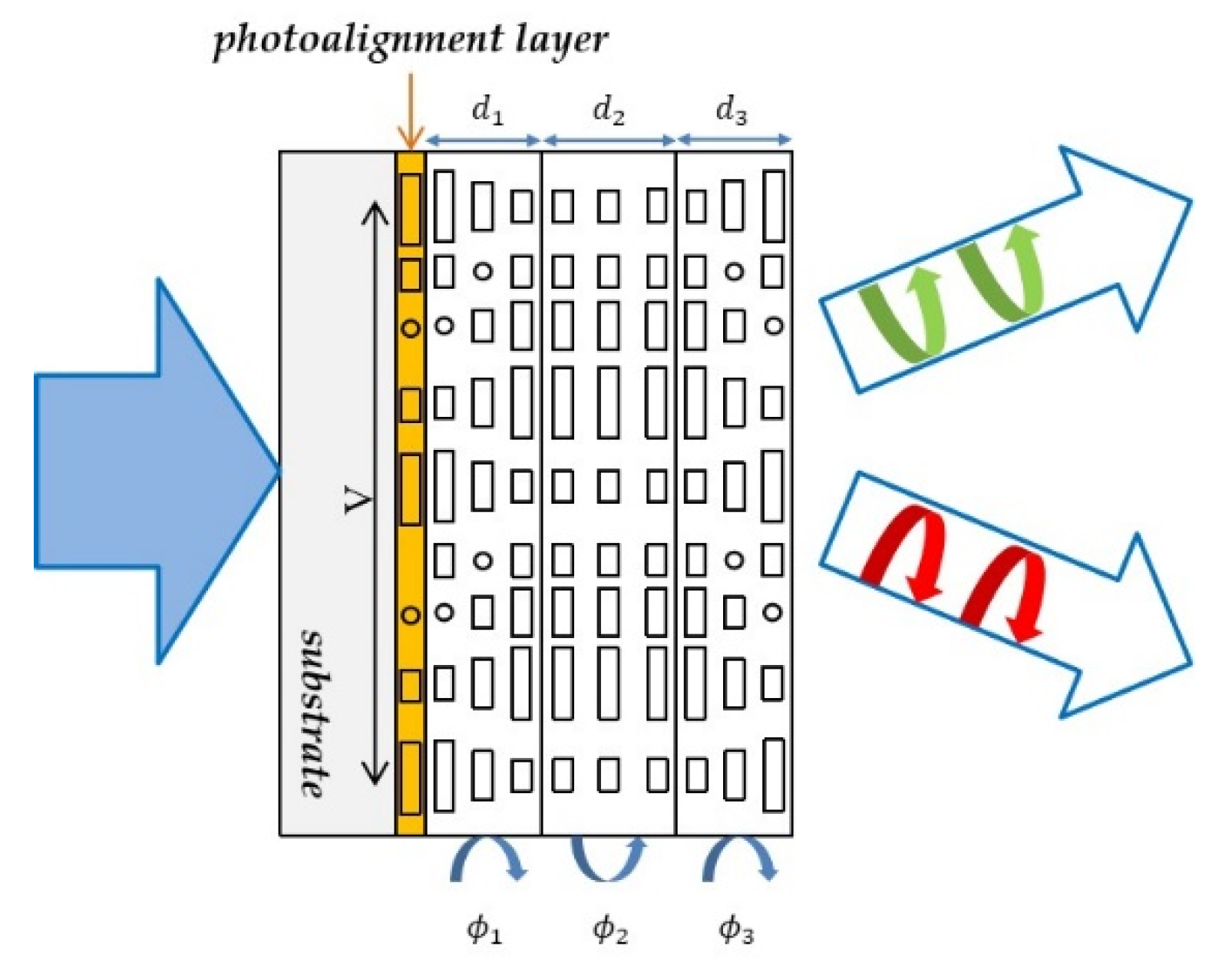
As is mentioned above, although the dual-layer twisted PG has wider spectral bandwidth than the traditional one, it still cannot meet the application requirements (especially its angular response [41]). So, a three-layer multi-twist grating structure was proposed by Zou and Wu et al. [35], which could achieve high efficiency in both visible light band and large incident angle. The device structure is shown in Figure 5. Note that the twist angle is exceedingly small (3.7° in 1.32 μm) in the 2nd layer according to simulation. So, they add no chiral dopant to the 2nd layer, and that brings negligible error to the efficiency performance.
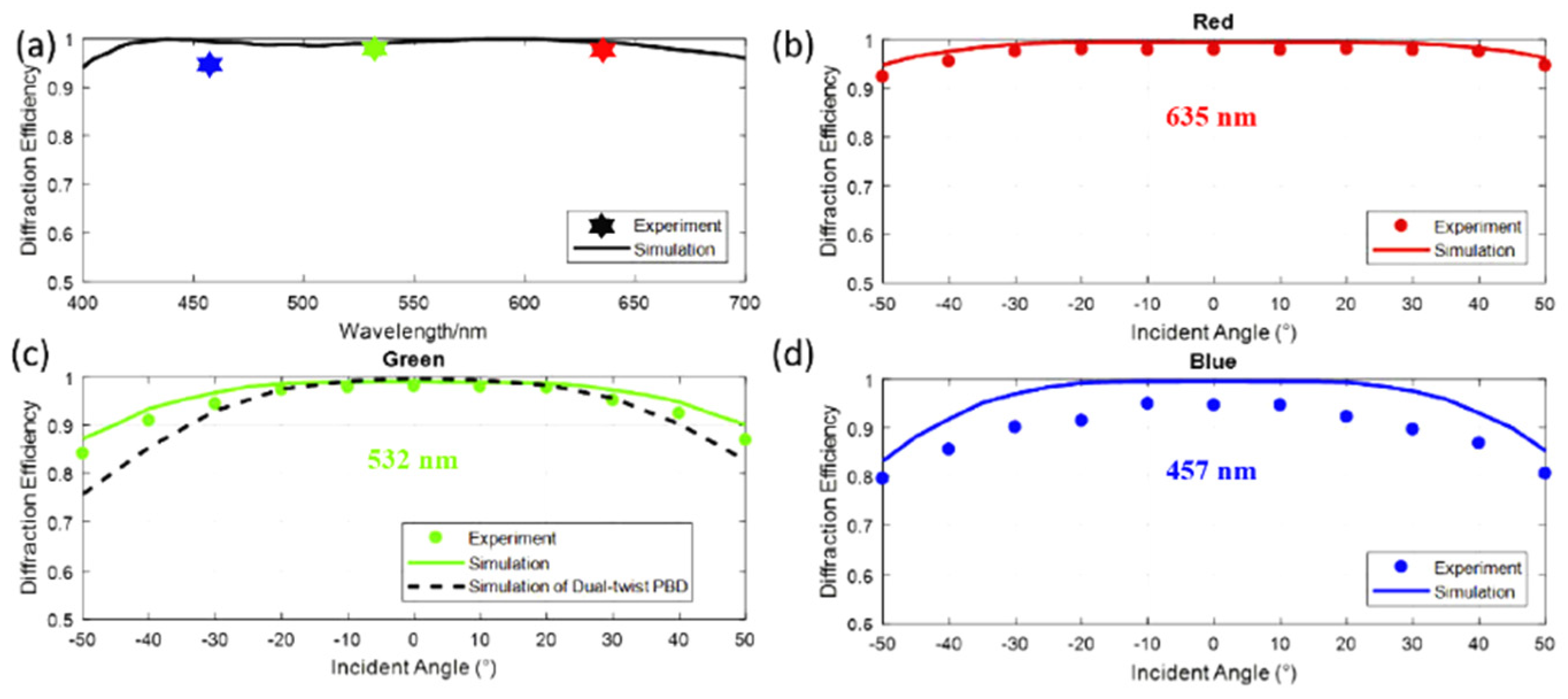
The rigorous coupled wave analysis (RCWA) method [42,43] is used to simulate their three-layer multi-twist grating structure, and several interchangeably optimization algorithms are used to optimize its parameters. Moreover, they reported the fabrication process and materials in detail. The thickness and the twist angle of each layer are accurately controlled by Jones matrix method combined with experiments. Compared with the angular response of double-twist PG, the three-layer twist PG (or called Pancharatnam–Berry phase deflector, PBD in their paper) has obvious advantages at a large incident angle. The results (Figure 6) showed that the diffraction efficiency of the three-layer twist PG at 50° in simulation and experiment is 87.2% and 84.1%, respectively, in this work, much higher than that of dual-twist PG (75.7%) [35].
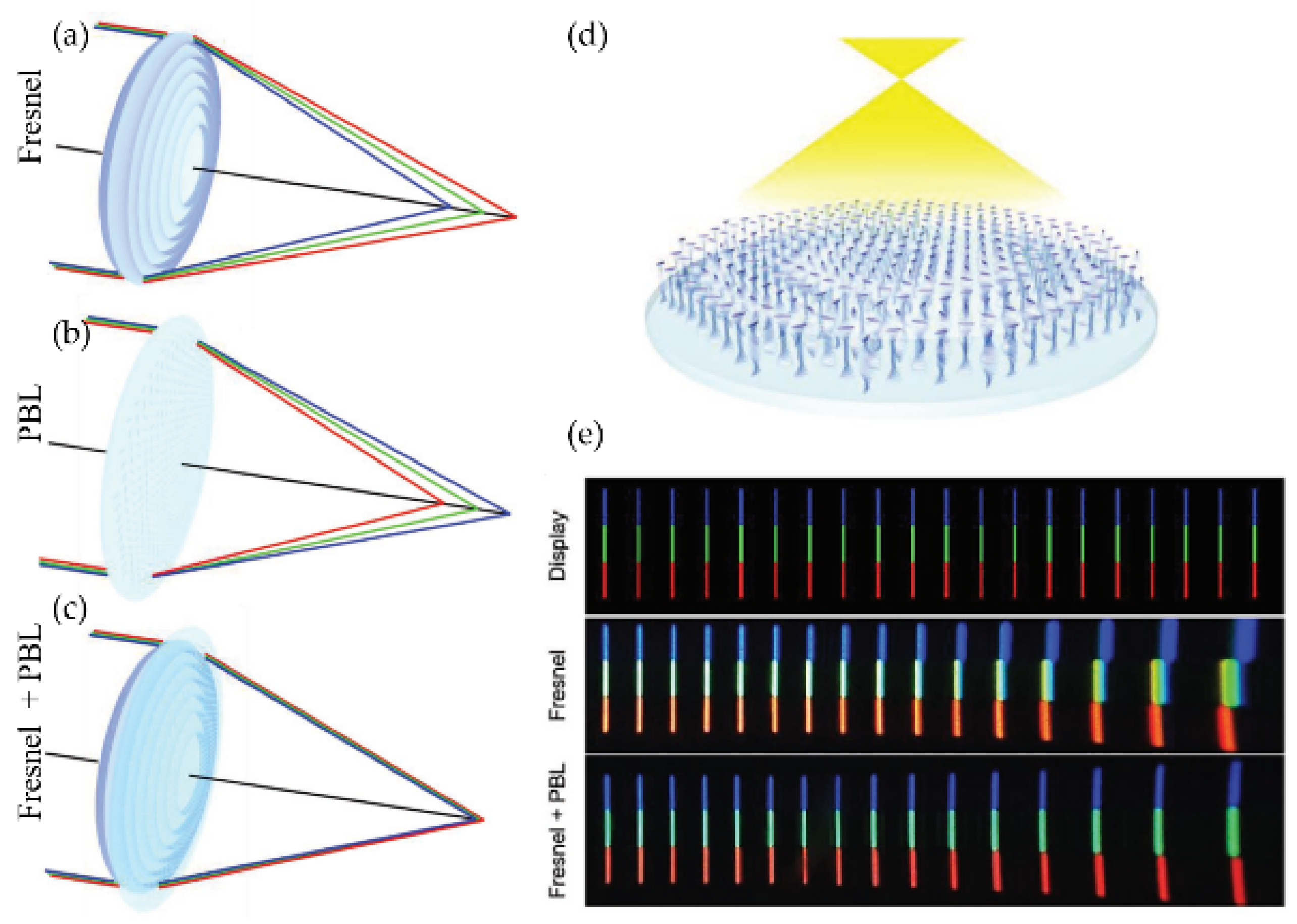
Based on the idea of broadband PGs above, in 2020, Tao Zhan et al. [11] proposed a three-layer multi-twist polarization lens (or Pancharatnam-Berry lens, PBL). Combining with a refractive Fresnel lens, the chromatic aberration (CA) of the system was significantly improved. The opposite dispersion between each other illustrated in Figure 7a–c. It has a better bandwidth response and can cover most of the light from the display panel (diffraction efficiency > 95%), shown in Figure 7e. Meanwhile, a broadband circular polarizer was used to prevent the ghost image caused by 0th leakage of PBLs, and a clear image was obtained in 100° field of view. The excellent bandwidth and field of view response effectively reduce the complexity of the optical system and perfectly fit the requirements of VR/AR and near-eye display, etc.
4. High Efficiency and Large-Angle Diffraction Gratings and Lenses—Based on Bragg Diffraction Generated by Twisted LC Structures
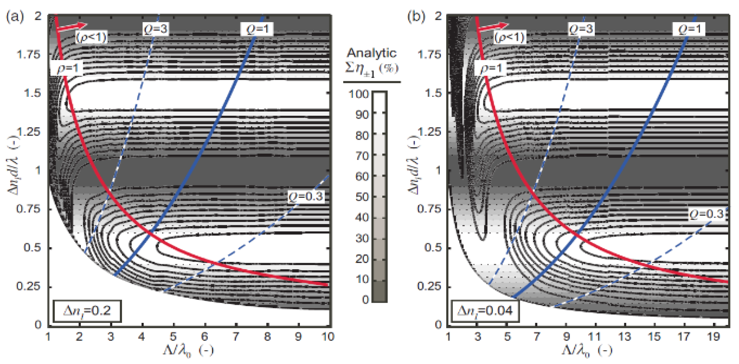
A much smaller horizontal period Λ is required to increase the diffraction angle. Oh, Escuti et al. [18] simulated the diffraction efficiency of LCPGs at different diffraction angles (which embodied the horizontal period Λ) and birefringence Δn using the finite difference time domain (FDTD) method. In their work, parameter Q and ρ were introduced to describe the relationship between the diffraction efficiency and the period of LCPGs.
Results show in Figure 8, illustrated that a LCPG can have near-100% diffraction efficiency only when ρ < 1. That is, the efficiency will be reduced sharply if grating period Λ is comparable to the indecent wavelength λ, especially when a LC material with low Δn is utilized (Figure 8b).
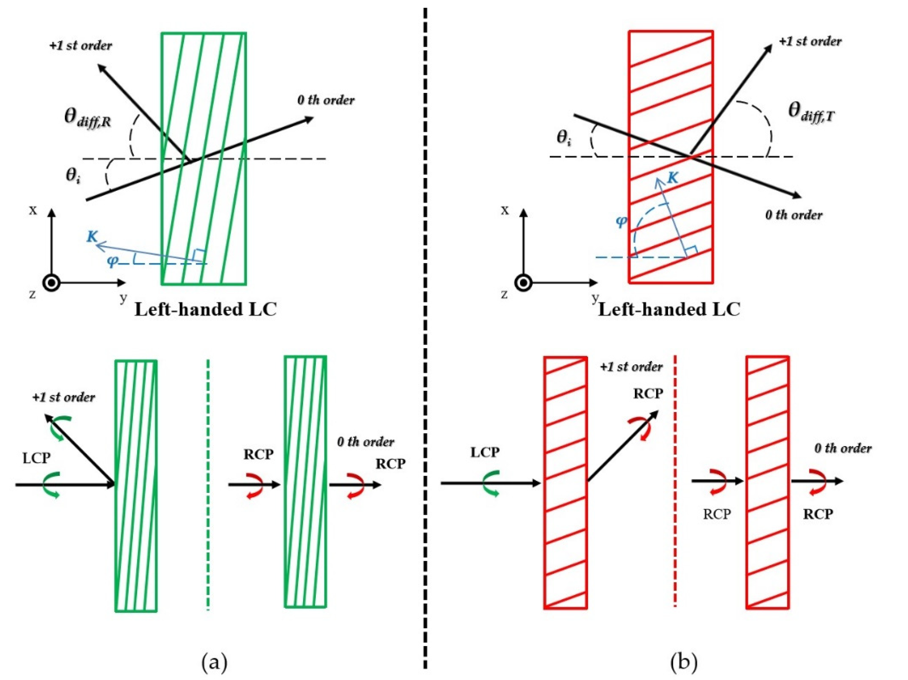
Therefore, in order to achieve a large-angle diffraction with high efficiency, another form of grating diffraction, i.e., Bragg diffraction, needs to be considered. In Section 2, we have mentioned that Bragg diffraction could be achieved with a reasonable design of the horizontal period Λx, and the pitch of LC (P = 2Λy). By adjusting the two pitches (Λx, Λy), both reflective and transmissive gratings can be formed [7], as shown in Figure 9. When the incident angle θi = 0°, the 1st diffraction angle θdiff can be defined by the slanted angle φ, illustrated in Equation (5) below, and at this point, a larger diffraction angle can be generated.
In addition, Bragg gratings with twisted LC structures have the characteristic of polarization selection [7,8,31,44]. It will only diffract the circularly polarized incident light which has the same handedness of the LC structure (the 1st order), while the opposite circularly polarization will be transmitted directly (the 0th order) [45,46]. For the diffraction beam, the polarization state depends on the method of the Bragg grating: for a reflective Bragg grating, the diffraction beam will keep the same handedness of the incident beam, while for a transmissive Bragg grating, it will be converted to the orthogonal polarization.
4.1. Reflective Bragg Volume Polarization Gratings (PVGs) and Lens (PVLs)
Since PVGs have excellent wavelength and polarization selectivity, they can be used in various devices, such as beam steering, optical switches, and wearable displays, etc, which have been reviewed in detail by Kun Yin et al. 2020 [14]. Here we select several representative works to expound.
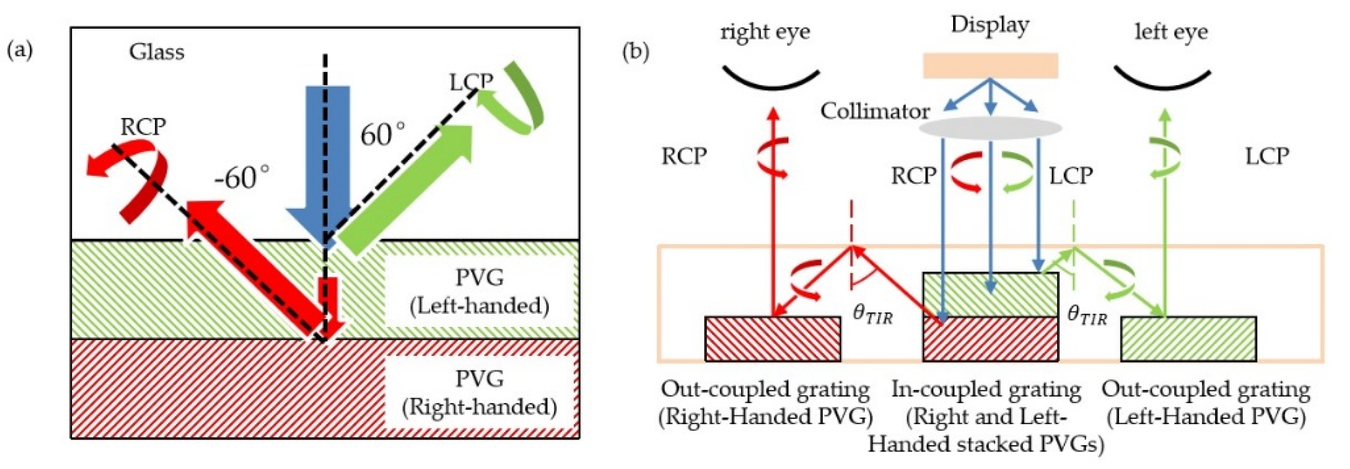
According to the polarization selectivity of PVGs, in 2016 Weng et al. [7] designed a reflective PVG for 2D/3D wearable displays and performed a series of theoretical simulations. They used a dual-layer twisted structure with opposite directions in the PVGs, where Λx = 404.6 nm, Λy = 233.6 nm, Δn = 0.2, the slant angle φ of the refractive index plane is 30°, and 4 μm for each layer. As shown in Figure 10, for the left-handed and right-handed circular incident light at 550 nm, they can be reflected in two different directions (±60°) at the same time. As a result, 3D near-eye display devices can be obtained by using only one panel. Then in 2017, Lee et al. [8] prepared a high-efficiency PVG for augmented reality (AR) displays. The measured diffraction efficiency can reach 90% @ 650 nm (Λx = 540 nm, Λy = 250 nm, d = 3 μm, Δn = 0.18) and the deflection angle can reach 50°. Using three different chiral LC materials (1.4 wt%, 1.8 wt% and 2.2 wt%, 3 different concentrations of chiral dopant R5011 mixed in LC monomer RM257), a three-period reflective PVG with was fabricated. The test results showed that the sample can broaden the bandwidth.
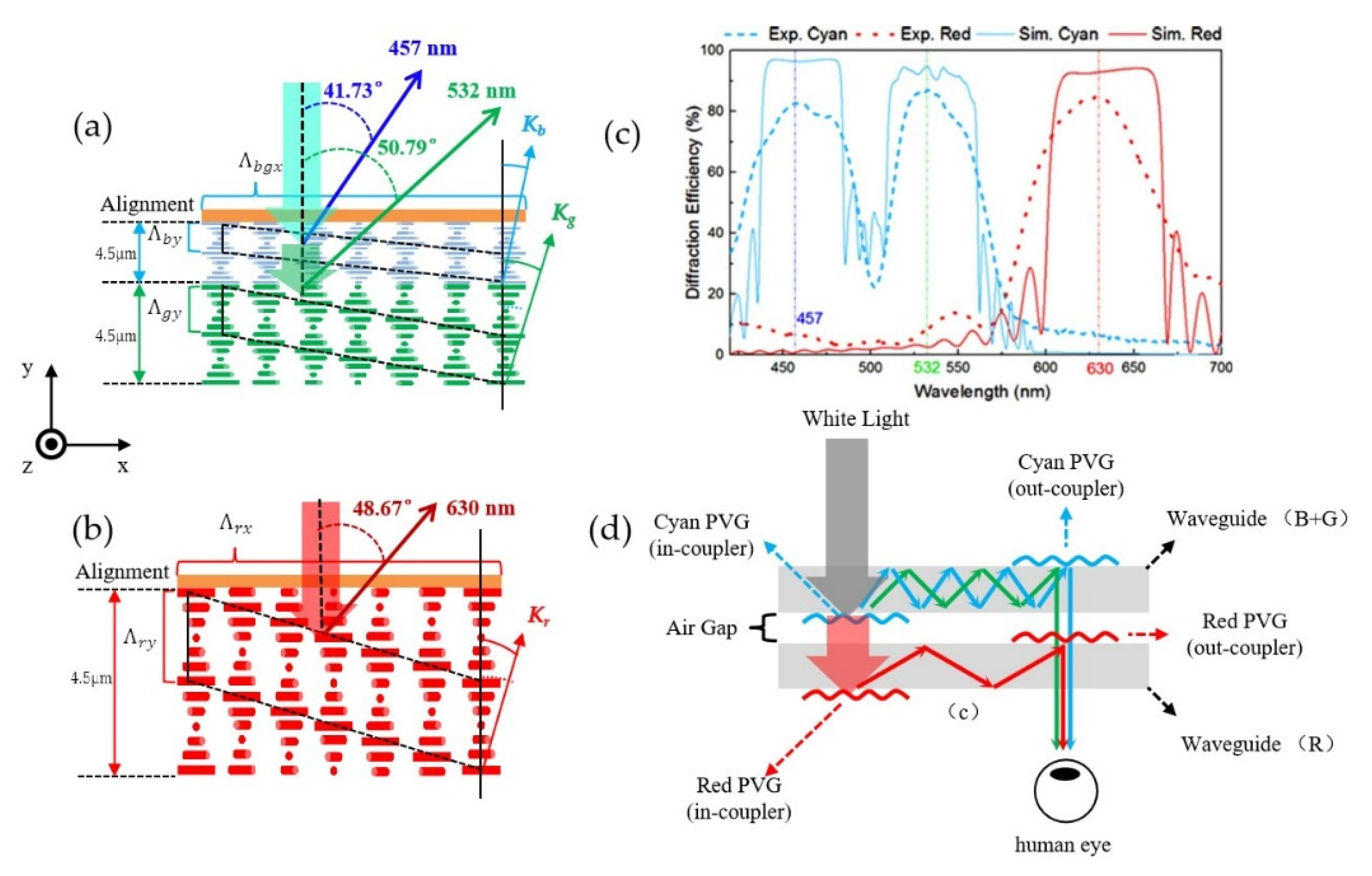
In 2018, Weng et al. proposed a PVG-based dual-layer waveguide which could be applied in full-color AR displays [10]. In order to ensure the field of view, two PVGs are placed in different waveguide layers to separate the propagations of red (R) and cyan (GB) spectra light, shown in Figure 11a–c. The prepared PVGs showed a higher diffraction efficiency (over 80%) with large diffraction angles at spectra of RGB (630 nm; 532 nm; 457 nm). The prototype, in Figure 11d, showed a clear full-color display with an approximately 35° diagonal field of view and the transparency was up to 72%.
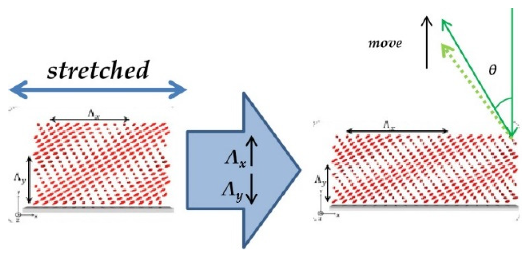
In 2019, Kun Yin et al. [47] proposed a PVG attached to a flexible material film to make it stretchable and rollable. A 3-μm thick PVG on a 160-μm thick Polydimethylsiloxane (PDMS) substrate was fabricated. With mechanical stretching, the horizontal direction of the PVG was lengthened and the total thickness reduced, as shown in Figure 12. That is, the Bragg period ΛB values were changed, thus shifting the reflection band and deflection angle. In their work, the central wavelength blue-shifted from 507.5 nm to 474.5 nm, and the deflection angle could be modulated from 35° to 46.5° with a tuning range of 11.5°. This study showed a promising potential for laser beam steering applications and provided a possibility for fabricating flexible devices.
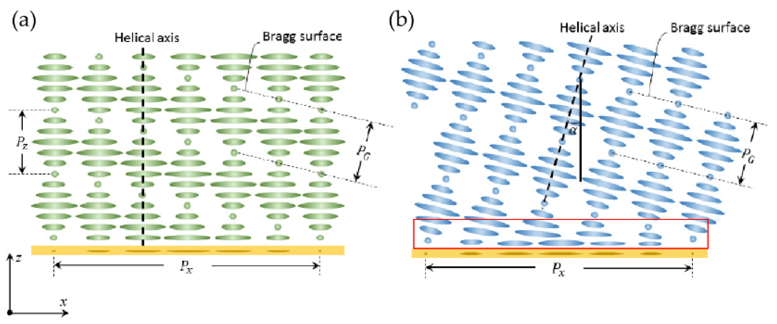
It should be noted that, some latest experiments [14] and simulation [30,33] prove that the LC director configuration in a PVG is not planar (Figure 13a); instead, it tends to present a slanted structure (Figure 13b) due to the trend of the lowest volume free energy [14]. The optical properties of planar and slanted PVGs are very similar in terms of diffraction efficiency, wavelength, and angular response. However, for polarization response, the two structures show different performance. At normal incidence, the diffracted light from the planar PVG significantly deviates from the circular polarization, while the circular polarization state of the slanted PVG remains.
Reflective polarization volume lenses (or rPVLs) have attracted much more attention in recent years because they can fold the optical path. It could be regarded as a combination of a slanted PVG and a lens while still maintaining the selective characteristics of Bragg diffraction on the polarization and wavelength.
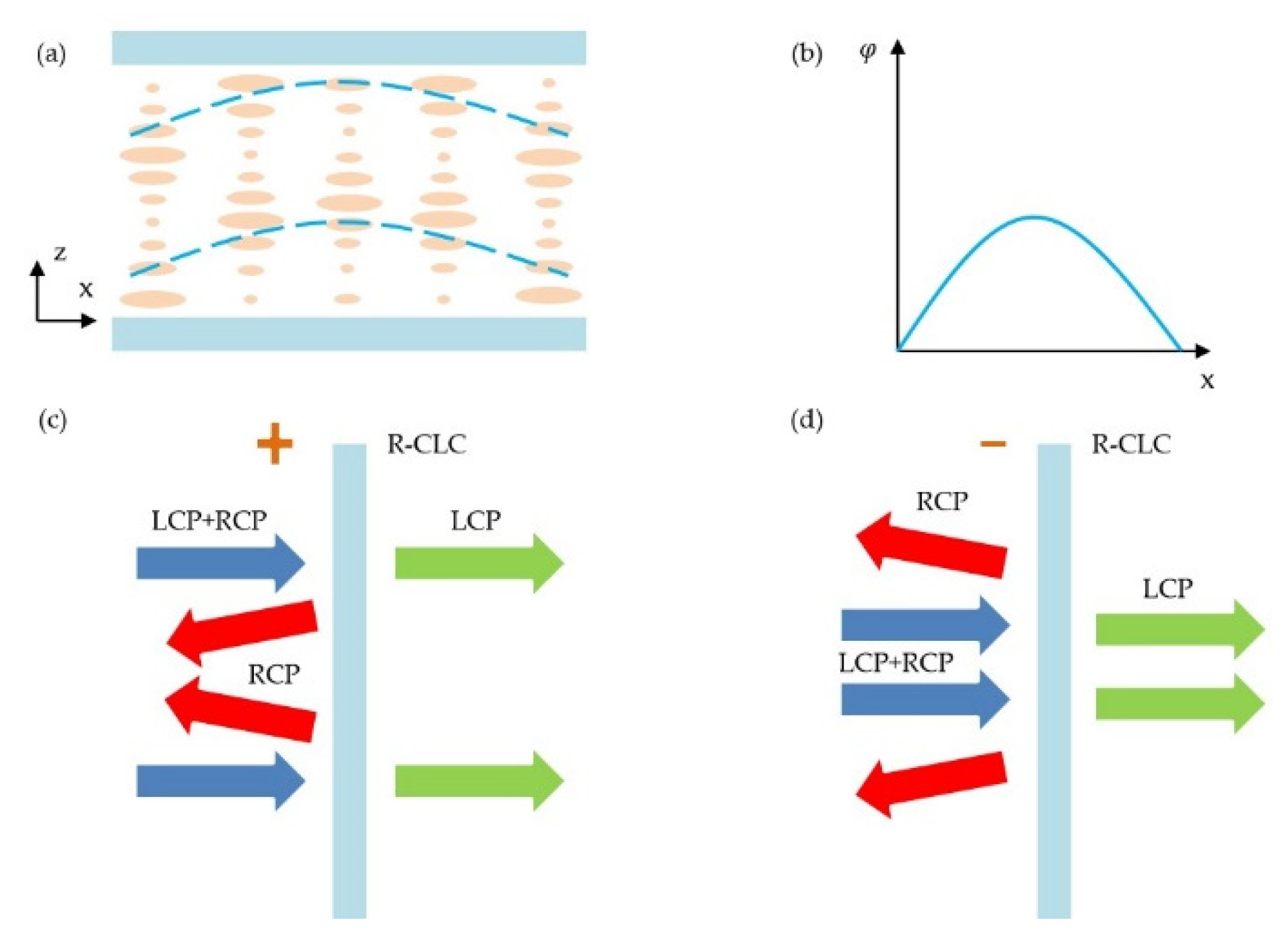
In 2020, Zhan Tao et al. [12] proposed a series of cholesteric LC lenses (CLC lenses) with low f/# = f/D (2, 0.9, 0.45 and 0.33, respectively, diameter D = 2.45 cm) at 550 nm using the optical imprinting technique. The twisting structure of Ch-LC provided a phase change, as shown in Figure 14a,b. These lenses have the same polarization selectivity as Ch-LC. When the circular incident light incident from different directions, the lens presents different effects (positive “+” or negative “-” focal) as shown in Figure 14c,d. The results showed that the diffraction efficiency can reach about 85% and the imaging quality was good for the circular polarization states at normal incidence. CLC lenses could be used as a compact element for expanding the view field in VR/AR displays.
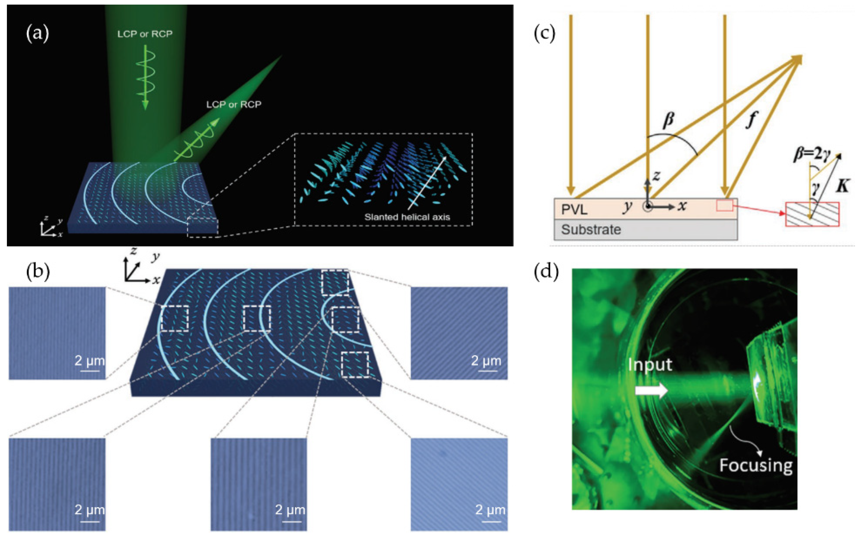
Subsequently, Kun Yin et al., who are from the same research group [13], proposed an off-axis reflective polarized volume lens (rPVL), with a low f/# of 0.825 and could obtain an off-axis diffraction angle of 45°, shown in Figure 15a,d. The rPVL has a parabolic phase profile in x-y plane macroscopically, while approximately a PVG with linear phase change in a tiny area (Figure 15b). Besides, the rPVL presents a slanted helical axis (slant angle γ). Thus, the incident circular polarized light with the same handedness of the rPVL will be reflected and converged with an off-axis angle β (β = 2γ), illustrated in Figure 15c. The thin (about 1 μm thick) rPVLs are designed at Bragg wavelength (λ = 605 nm, 532 nm, and 450 nm) with a measured efficiency of 60%, 60%, and 55% correspondingly. There is still much room for improvement. According to their later test, the actual focal spot size is 2.5× larger than the theoretical one, which could be corrected with appropriate optical (AO) systems. The efficiency will also increase by increasing the thickness.
4.2. Transmissive Bragg PGs
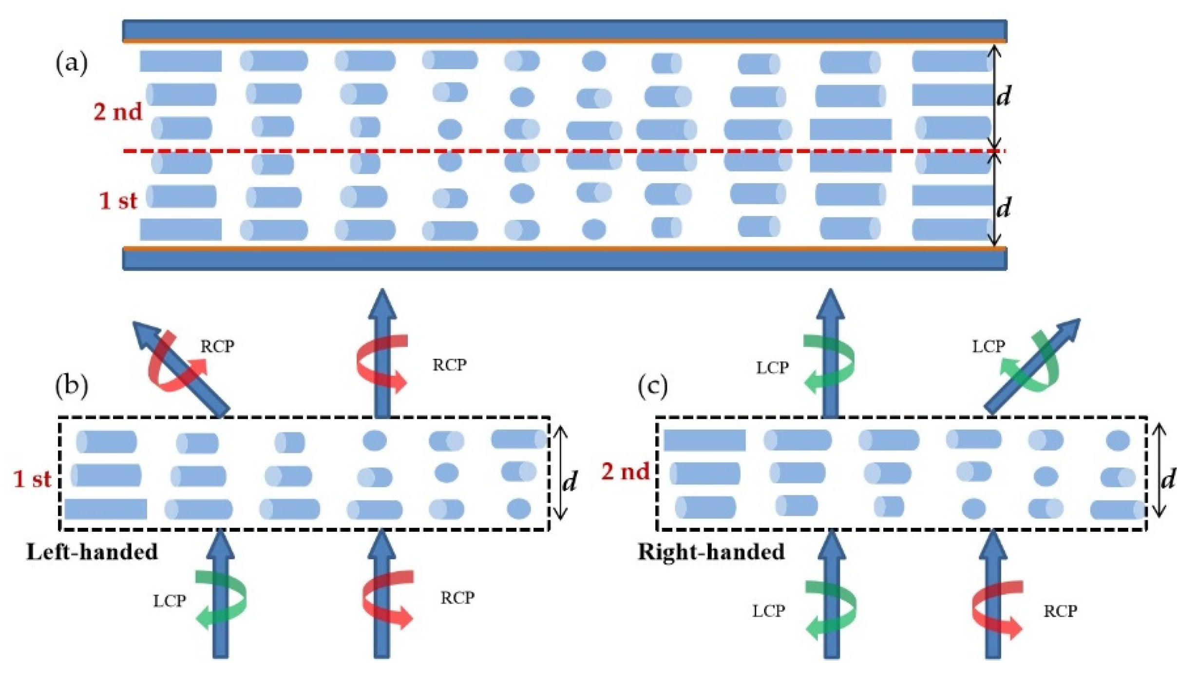
Philip J. Bos et al. [21,45,48] reported a series of large-angle Bragg PGs using twisting structures in 2015 and 2017, called a dual-twist Pancharatnam phase deflector (DTPPD) in their papers. Here we regard them as transmitted Bragg PGs in the selective circular reflection region. Figure 16 is the proposed antisymmetric dual-twist structure, which is similar to the structure proposed by Oh [22] and Li Tan [25]. The single-twist structure only deflects one of the circularly polarized lights while the other is transmitted. Both left- and right-hand circular polarizations can be deflected using an antisymmetric dual-twist structure [45,48]; the research discussed the relationship between retardation and twist angle at specific deflection angles and birefringence to get high efficiency by the FDTD method. Then they optimized Bragg PGs with 20°, 40°, 60°, and 80° deflection angles using birefringence values of Δn = 0.106, 0.179 and 0.3, respectively. A well-performing dual-twist structure was optimized at the wavelength of 633 nm and 40° deflection angle with the parameters that thickness just met half-wave retardation and twist angle was 75°. Cheng et al. designed and fabricated high-efficiency large-angle transmitted Bragg PGs based on an antisymmetric dual-twist structure. It could deflect ±40° with 90% diffraction efficiency at a 633 nm wavelength.
Xiao Xiang et al. [28] analyzed the properties of polymer LC Bragg PGs based on twist structure by anisotropic rigorous coupled wave analysis. Without paraxial approximation, they simulated the most important diffraction properties, including the angular, spectral, and polarization responses. They overcame the critical thickness problem by spin-coating multiple sublayers and fabricated a series of single-layer transmitted Bragg PGs with Λ = 335 nm for λ = 450 nm. They varied the chiral material concentration to adjust twist angle ϕ and slant angle θG. The experimental results showed that at the same incident wavelength, the gratings with different twist angle had different peak incident angles and peak power.
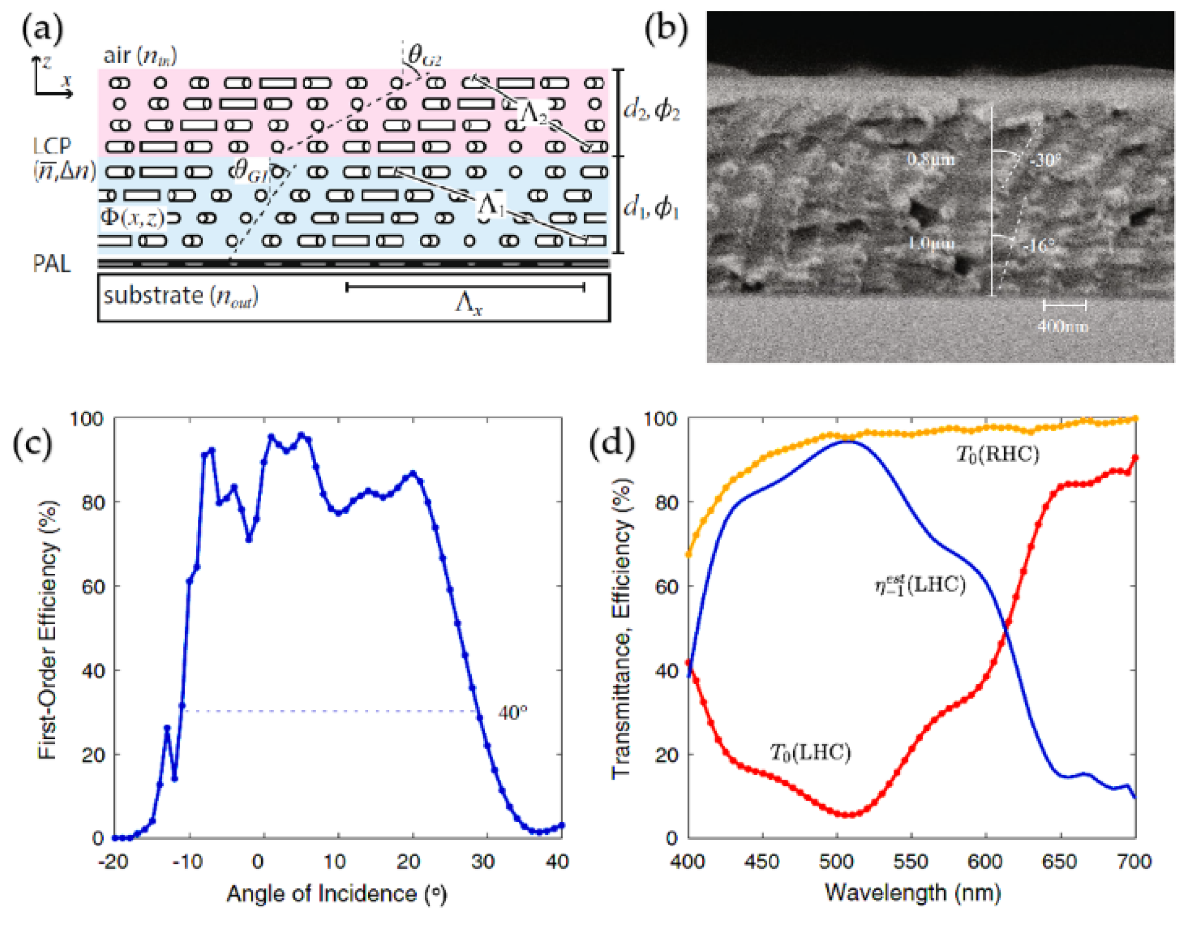
Subsequently, they reported a transmitted Bragg PG formed by a double-layer slanted structure [29], shown in Figure 17a,b. Angular bandwidth was significantly increased by arranging two slanted grating layers within the same monolithic film under the premise of ensuring the large deflection angle and broadband. The fabricated sample has excellent properties such as 40° angular bandwidth (Figure 17c), 200 nm spectral bandwidth, 76% for average efficiency, and 96% for peak efficiency (Figure 17d).
5. Conclusions and Outlook
In this paper, the research progress and working principle of twisting-based LCPGs and LCPLs in recent years are reviewed. We found that the twisting structures work in different methods in different devices. For a broadband PG, twisted LCs work in the short-wavelength circular birefringence region, presenting the property of retardation compensation. While for transmissive Bragg LCPGs and reflective PVGs, it works in the Bragg region. The slanted and periodical refractive index planes were established by combining the pitch of a twisted LC and the horizontal period on the photo-alignment layer. Based on these theoretical analyses, more devices with excellent characteristics have been achieved. Especially for PVGs and PVLs, they enable promising applications for wearable displays.
Further work in the field of studying novel twisting structures based on combining different method is highly desirable. For instance, the long-wavelength circular birefringence region of twisted LCs has not been used so far, which might present a good performance in infrared (IR) applications. Additionally, combining transmissive Bragg PGs and reflective PVG in one element might gain attention in novel optical systems like waveguides for beam steering and AR display. We believe these studies will gain tremendous applied in the very near future.
Author Contributions
Writing—original draft preparation, S.Z., W.C. and Y.Y.; writing—review and editing, S.Z., W.C., Y.Y., S.L. and J.C.; supervision, Q.W. and Q.M. All authors have read and agreed to the published version of the manuscript.
Funding
This research was funded by National Natural Science Foundation of China, grant number 11974345, 61975202, U2030101, 11604327, 61775212.
Conflicts of Interest
The authors declare no conflict of interest.
References
- Ramachandran, G.N.; Ramaseshan, S. Magneto-optic rotation in birefringent media—Application of the Poincaré Sphere. J. Opt. Soc. Am. 1952, 42, 49–52. [Google Scholar] [CrossRef]
- Gutiérrez-Vega, J.C. Pancharatnam—Berry phase of optical systems. Opt. Lett. 2011, 36, 1143–1145. [Google Scholar] [CrossRef]
- Pancharatnam, S. Generalized Theory of Interference, and Its Applications. In Proceedings—Mathematical Sciences; Springer International Publishing: New York, NY, USA, 1956; Volume 44, pp. 247–262. [Google Scholar]
- Nicolescu, E.; Escuti, M.J. Polarization-independent tunable optical filters based on liquid crystal polarization gratings. Proc. SPIE 2007, 6654, 1–12. [Google Scholar] [CrossRef]
- Packham, C.; Escuti, M.; Ginn, J.; Oh, C.; Quijano, I.; Boreman, G. Polarization gratings: A novel polarimetric component for astronomical instruments. Publ. Astron. Soc. Pac. 2010, 122, 1471–1482. [Google Scholar] [CrossRef] [Green Version]
- Chen, W.; Zhao, Z.; Wang, C.; Li, H.; Wei, R.; Zhang, S.; Peng, Z.; Liu, Y.; Wang, Q.; Mu, Q.; et al. Linear polarization grating combining a circular polarization grating with a special cycloidal diffractive quarter waveplate. Opt. Express 2019, 27, 33378–33390. [Google Scholar] [CrossRef]
- Weng, Y.; Xu, D.; Zhang, Y.; Li, X.; Wu, S.T. Polarization volume grating with high efficiency and large diffraction angle. Opt. Express 2016, 24, 17746–17759. [Google Scholar] [CrossRef] [PubMed]
- Lee, Y.H.; Yin, K.; Wu, S.T. Reflective polarization volume gratings for high efficiency waveguide-coupling augmented reality displays. Opt. Express 2017, 25, 27008–27014. [Google Scholar] [CrossRef] [PubMed]
- Liu, A.; Zhang, Y.; Weng, Y.; Shen, Z.; Wang, B. Diffraction efficiency distribution of output grating in holographic waveguide display system. IEEE Photon. J. 2018, 10, 1–10. [Google Scholar] [CrossRef]
- Weng, Y.; Zhang, Y.; Cui, J.; Liu, A.; Shen, Z.; Li, X.; Wang, B. Liquid-crystal-based polarization volume grating applied for full-color waveguide displays. Opt. Lett. 2018, 43, 5773–5776. [Google Scholar] [CrossRef]
- Zhan, T.; Zou, J.; Xiong, J.; Liu, X.; Chen, H.; Yang, J.; Liu, S.; Dong, Y.; Wu, S.T. Practical chromatic aberration correction in virtual reality displays enabled by cost-effective ultra-broadband liquid crystal polymer lenses. Adv. Opt. Mater. 2019, 8, 1–5. [Google Scholar] [CrossRef]
- Li, Y.; Zhan, T.; Wu, S.T. Flat cholesteric liquid crystal polymeric lens with low f-number. Opt. Express 2020, 28, 5875–5882. [Google Scholar] [CrossRef]
- Yin, K.; He, Z.; Wu, S.T. Reflective polarization volume lens with small f-number and large diffraction angle. Adv. Opt. Mater. 2020, 8, 1–7. [Google Scholar] [CrossRef]
- Yin, K.; Zhan, T.; Xiong, J.; He, Z.; Wu, S.T. Polarization volume gratings for near-eye displays and novel photonic devices. Crystals 2020, 10, 561. [Google Scholar] [CrossRef]
- Tan, L. Liquid Crystal Polarization Gratings and Their Applications. Ph.D. Thesis, Hong Kong University of Science and Technology, Hong Kong, China, 2013. [Google Scholar]
- Lin, Y.-H.; Wang, Y.-J.; Reshetnyak, V. Liquid crystal lenses with tunable focal length. Liq. Cryst. Rev. 2018, 5, 111–143. [Google Scholar] [CrossRef]
- Algorri, J.F.; Zografopoulos, D.C.; Urruchi, V.; Sánchez-Pena, J.M. Recent advances in adaptive liquid crystal lenses. Crystals 2019, 9, 272. [Google Scholar] [CrossRef] [Green Version]
- Oh, C.; Escuti, M.J. Numerical analysis of polarization gratings using the finite-difference time-domain method. Phys. Rev. A 2007, 76, 1–8. [Google Scholar] [CrossRef] [Green Version]
- Oh, C. Broadband Polarization Gratings for Efficient Liquid Crystal Display, Beam Steering, Spectropolarimetry, and Fresnel Zone Plate. Ph.D. Thesis, North Carolina State University, Raleigh, NC, USA, 2009. [Google Scholar]
- Xiangjie, Z.; Jiazhu, D.; Dayong, Z.; Cangli, L.; Yongquan, L. Oblique incidence effect on steering efficiency of liquid crystal polarization gratings used for optical phased array beam steering amplification. Opt. Rev. 2016, 23, 713–722. [Google Scholar] [CrossRef]
- Cheng, H.H.; Bhowmik, A.K.; Bos, P.J. Concept for a transmissive, large angle, light steering device with high efficiency. Opt. Lett. 2015, 40, 2080–2083. [Google Scholar] [CrossRef]
- Oh, C.; Shaw, J.A.; Escuti, M.J.; Tyo, J.S. Achromatic polarization gratings as highly efficient thin-film polarizing beamsplitters for broadband light. Proc. SPIE 2007, 6682, 1–12. [Google Scholar] [CrossRef]
- Oh, C. Achromatic diffraction from polarization gratings with high efficiency. Opt. Lett. 2008, 33, 2287–2289. [Google Scholar] [CrossRef]
- Tan, L.; Ho, J.Y.; Kwok, H.S. Extended Jones matrix method for oblique incidence study of polarization gratings. Appl. Phys. Lett. 2012, 101, 1–4. [Google Scholar] [CrossRef]
- Tan, L.; Ho, J.Y.; Srivastava, A.K.; Kwok, H.S. A simplified model for the optimization of LC photonic elements. IEEE Photon. Technol. Lett. 2014, 26, 1096–1099. [Google Scholar] [CrossRef] [Green Version]
- Li, L.; Kim, J.; Shi, S.; Escuti, M.J.; Khoo, I.C. Color-selective geometric phase lens for apochromatic lens system. Proc. SPIE 2020, 11472, 1–15. [Google Scholar] [CrossRef]
- Xiang, X.; Escuti, M.J. Numerical analysis of Bragg regime polarization gratings by rigorous coupled-wave analysis. Proc. SPIE 2017, 10127, 1–7. [Google Scholar] [CrossRef]
- Xiang, X.; Kim, J.; Komanduri, R.; Escuti, M.J. Nanoscale liquid crystal polymer Bragg polarization gratings. Opt. Express 2017, 25, 19298–19308. [Google Scholar] [CrossRef] [Green Version]
- Xiang, X.; Kim, J.; Escuti, M.J. Bragg polarization gratings for wide angular bandwidth and high efficiency at steep deflection angles. Sci. Rep. 2018, 8, 1–6. [Google Scholar] [CrossRef] [Green Version]
- Xiang, X.; Escuti, M.J. Numerical analysis of Bragg polarization gratings. J. Opt. Soc. Am. B 2019, 36, D1–D8. [Google Scholar] [CrossRef]
- Yeh, P.; Gu, C. Optics of Liquid Crystal Displays, 2nd ed.; John Wiley & Sons Inc.: Hoboken, NJ, USA, 2009; pp. 461–484. [Google Scholar]
- Yoon, K.C.; Yoon, H.C.; Kim, K.Y.; Cui, H.; Park, J.R.; Jang, W.; Park, O.O. Application of twisted retarders to a cholesteric liquid crystal polarizer for the control of output polarization states. Jpn. J. Appl. Phys. 2009, 48, 1–6. [Google Scholar] [CrossRef]
- Lee, Y.-H.; He, Z.; Wu, S.-T. Optical properties of reflective liquid crystal polarization volume gratings. J. Opt. Soc. Am. B 2019, 36, D9–D12. [Google Scholar] [CrossRef]
- Yousefzadeh, C.; Jamali, A.; McGinty, C.; Bos, P.J. “Achromatic limits” of Pancharatnam phase lenses. Appl. Opt. 2018, 57, 1151–1158. [Google Scholar] [CrossRef] [PubMed]
- Zou, J.; Zhan, T.; Xiong, J.; Wu, S.T. Broadband wide-view Pancharatnam-Berry phase deflector. Opt. Express 2020, 28, 4921–4927. [Google Scholar] [CrossRef]
- Wu, T.X.; Huang, Y.; Wu, S.-T. Design optimization of broadband linear polarization converter using twisted nematic liquid crystal. Jpn. J. Appl. Phys. 2003, 42, L39–L41. [Google Scholar] [CrossRef]
- Shen, S.; She, J.; Tao, T. Optimal design of achromatic true zero-order waveplates using twisted nematic liquid crystal. J. Opt. Soc. Am. A 2005, 22, 961–965. [Google Scholar] [CrossRef]
- Komanduri, R.K.; Lawler, K.F.; Escuti, M.J. Multi-twist retarders: Broadband retardation control using self-aligning reactive liquid crystal layers. Opt. Express 2013, 21, 404–420. [Google Scholar] [CrossRef] [Green Version]
- Bigelow, J.E.; Kashnow, R.A. Poincaré sphere analysis of liquid crystal optics. Appl. Opt. 1977, 16, 2090–2096. [Google Scholar] [CrossRef]
- Xiong, J.; Chen, R.; Wu, S.T. Device simulation of liquid crystal polarization gratings. Opt. Express 2019, 27, 18102–18112. [Google Scholar] [CrossRef] [PubMed] [Green Version]
- Xiang, X.; Escuti, M.J. Numerical modeling of polarization gratings by rigorous coupled wave analysis. Proc. SPIE 2016, 9769, 1–7. [Google Scholar] [CrossRef]
- Moharam, M.G.; Pommet, D.A.; Grann, E.B.; Gaylord, T.K. Stable implementation of the rigorous coupled-wave analysis for surface-relief gratings: Enhanced transmittance matrix approach. J. Opt. Soc. Am. A 1995, 12, 1077–1086. [Google Scholar] [CrossRef]
- Moharam, M.G.; Gaylord, T.K. Rigorous coupled-wave analysis of planar-grating diffraction. J. Opt. Soc. Am. A 1981, 71, 811–818. [Google Scholar] [CrossRef]
- Kobashi, J.; Yoshida, H.; Ozaki, M. Planar optics with patterned chiral liquid crystals. Nat. Photon. 2016, 10, 389–392. [Google Scholar] [CrossRef]
- Gao, K.; McGinty, C.; Payson, H.; Berry, S.; Vornehm, J.; Finnemeyer, V.; Roberts, B.; Bos, P. High-efficiency large-angle Pancharatnam phase deflector based on dual-twist design. Opt. Express 2017, 25, 6283–6293. [Google Scholar] [CrossRef] [PubMed]
- Sakhno, O.; Gritsai, Y.; Sahm, H.; Stumpe, J. Fabrication and performance of efficient thin circular polarization gratings with Bragg properties using bulk photo-alignment of a liquid crystalline polymer. Appl. Phys. B 2018, 124, 1–10. [Google Scholar] [CrossRef]
- Yin, K.; Lee, Y.H.; He, Z.; Wu, S.T. Stretchable, flexible, rollable, and adherable polarization volume grating film. Opt. Express 2019, 27, 5814–5823. [Google Scholar] [CrossRef]
- Cheng, H.; Bhowmik, A.K.; Bos, P.J. Analysis of a dual-twist Pancharatnam phase device with ultrahigh-efficiency large-angle optical beam steering. Appl. Opt. 2015, 54, 10035–10043. [Google Scholar] [CrossRef] [PubMed]
Figure 1.
Schematic drawing of a twisting liquid crystal (LC) structure.

Figure 2.
Schematic drawing of Bragg diffraction in (a) crystalline and (b) twisting LC.

Figure 3.
Schematic drawing of a tilted grating structure combining the horizontal and the vertical periods, Λx and Λy. The refractive index distribution presents a series of surfaces with tilt angle φ.
Figure 3.
Schematic drawing of a tilted grating structure combining the horizontal and the vertical periods, Λx and Λy. The refractive index distribution presents a series of surfaces with tilt angle φ.

Figure 4.
(a) Schematic drawing of the opposite twisted dual-layer achromatic polarization gratings (side view); (b) Schematic drawing of the diffraction geometry of the achromatic PG (linear polarized incident); Theoretical diffraction efficiency of the achromatic PG; (c) First-order efficiency spectra versus twist angle and (d) for Φ = 70° compared with the circular PG [23]. Reprinted with permission from [23] © The Optical Society.

Figure 5.
The structure of three-layer multi-twist PG, (d1, d2, d3) = (0.9, 1.32, 0.88) μm, and the corresponding twist angle (Φ1, Φ2, Φ3) = (69.4°, 3.7°, 64°).
Figure 5.
The structure of three-layer multi-twist PG, (d1, d2, d3) = (0.9, 1.32, 0.88) μm, and the corresponding twist angle (Φ1, Φ2, Φ3) = (69.4°, 3.7°, 64°).

Figure 6.
Simulated and measured results: spectral (a) and angular response at (b) R (635 nm), (c) G (532 nm), (d) B (457 nm) of the three-layer multi-twist PBD [35]. Adapted with permission from [35] © The Optical Society.

Figure 7.
Schematic drawing of chromatic aberrations (CAs) in (a) a refractive Fresnel lens, (b) a diffractive Pancharatnam-Berry lens (PBL) and (c) the hybrid lens. (d) Schematic illustration of a CA lens. (e) Half-field CA testing (RGB pixels of LCD) [11]. Copyright 2019, WILEY-VCH.
Figure 7.
Schematic drawing of chromatic aberrations (CAs) in (a) a refractive Fresnel lens, (b) a diffractive Pancharatnam-Berry lens (PBL) and (c) the hybrid lens. (d) Schematic illustration of a CA lens. (e) Half-field CA testing (RGB pixels of LCD) [11]. Copyright 2019, WILEY-VCH.

Figure 8.
A comparison between numerical finite difference time domain (FDTD) calculation and analytical estimate is shown for (a) Δn = 0.2 and (b) Δn = 0.04, respectively [18]. Copyright 2007, The American Physical Society.
Figure 8.
A comparison between numerical finite difference time domain (FDTD) calculation and analytical estimate is shown for (a) Δn = 0.2 and (b) Δn = 0.04, respectively [18]. Copyright 2007, The American Physical Society.

Figure 9.
Schematic drawing of (a) reflective (b) transmissive left-handed Bragg gratings. Note that the 0th order is the transmitted beam without diffraction. Both gratings only diffract the circularly polarization state which has the same handedness of the LC structure.
Figure 9.
Schematic drawing of (a) reflective (b) transmissive left-handed Bragg gratings. Note that the 0th order is the transmitted beam without diffraction. Both gratings only diffract the circularly polarization state which has the same handedness of the LC structure.

Figure 10.
Schematic drawing for (a) the dual-layer polarized volume gratings (PVGs) used as an in-coupled grating of the planar waveguides in a 2D/3D wearable display device (b).
Figure 10.
Schematic drawing for (a) the dual-layer polarized volume gratings (PVGs) used as an in-coupled grating of the planar waveguides in a 2D/3D wearable display device (b).

Figure 11.
Schematic diagram of the designed PVGs for cyan (blue & green) (a) and red spectra (b). (c) Simulated and experimental spectra for the two PVGs at normal incidence. [10] Reprinted with permission from [10] © The Optical Society. (d) Schematic drawing of the prototype. PVGs are used as the waveguide couplers.

Figure 12.
A schematic drawing of the stretching process of PVG from unstrained state to strained state. Horizontal period lengthened and vertical period reduced. Diffraction angle θ shift (@ 532 nm) under different stretched lengths.
Figure 12.
A schematic drawing of the stretching process of PVG from unstrained state to strained state. Horizontal period lengthened and vertical period reduced. Diffraction angle θ shift (@ 532 nm) under different stretched lengths.

Figure 13.
Different LC director structures of (a) planar-PVG and (b) slanted-PVG. According to the latest research, the real configuration of LC director in PVG tend to be slanted like (b) [14].
Figure 13.
Different LC director structures of (a) planar-PVG and (b) slanted-PVG. According to the latest research, the real configuration of LC director in PVG tend to be slanted like (b) [14].

Figure 14.
(a) The polarization volume lense (PVL) twisting structure of the side view. (b) The corresponding phase profile. Lensing behaviors of a cholesteric LC (CLC) lens with (c) positive power and (d) negative power.
Figure 14.
(a) The polarization volume lense (PVL) twisting structure of the side view. (b) The corresponding phase profile. Lensing behaviors of a cholesteric LC (CLC) lens with (c) positive power and (d) negative power.

Figure 15.
(a) Schematic diagram of the beam focus formed by a rPVL and the LC director configuration inside. (b) Polarizing optical microscope (POM) images of rPVL at three locations. (c) Schematic diagram showing the coordinates of the rPVL. (d) Sample immersed in a cylindrical container to observe the off-axis focusing behavior and diffraction angle [13]. Copyright 2020, WILEY-VCH.

Figure 16.
(a) Illustration of antisymmetric dual-twist structure. The schematic of optical performance when LCP/RCP is input to the 1st (b) and the 2nd (c).
Figure 16.
(a) Illustration of antisymmetric dual-twist structure. The schematic of optical performance when LCP/RCP is input to the 1st (b) and the 2nd (c).

Figure 17.
(a) Illustration of the director profile of the two-slant LC polymer Bragg PG. (b) SEM micrograph of fabricated sample. Measured (c) angular response for LCP input polarization at λ = 532 nm, and (d) spectral response for circular input polarization at normal incidence [29].
Figure 17.
(a) Illustration of the director profile of the two-slant LC polymer Bragg PG. (b) SEM micrograph of fabricated sample. Measured (c) angular response for LCP input polarization at λ = 532 nm, and (d) spectral response for circular input polarization at normal incidence [29].

Publisher’s Note: MDPI stays neutral with regard to jurisdictional claims in published maps and institutional affiliations. |
© 2021 by the authors. Licensee MDPI, Basel, Switzerland. This article is an open access article distributed under the terms and conditions of the Creative Commons Attribution (CC BY) license (http://creativecommons.org/licenses/by/4.0/).
Share and Cite
MDPI and ACS Style
Zhang, S.; Chen, W.; Yu, Y.; Wang, Q.; Mu, Q.; Li, S.; Chen, J. Twisting Structures in Liquid Crystal Polarization Gratings and Lenses. Crystals 2021, 11, 243. https://doi.org/10.3390/cryst11030243
AMA Style
Zhang S, Chen W, Yu Y, Wang Q, Mu Q, Li S, Chen J. Twisting Structures in Liquid Crystal Polarization Gratings and Lenses. Crystals. 2021; 11(3):243. https://doi.org/10.3390/cryst11030243
Chicago/Turabian StyleZhang, Shiyuan, Wan Chen, Yang Yu, Qidong Wang, Quanquan Mu, Shixiao Li, and Jin Chen. 2021. "Twisting Structures in Liquid Crystal Polarization Gratings and Lenses" Crystals 11, no. 3: 243. https://doi.org/10.3390/cryst11030243
Note that from the first issue of 2016, this journal uses article numbers instead of page numbers. See further details here.