
Exit Pupil Expansion Based on Polarization Volume Grating

Joint International Research Laboratory of Information Display and Visualization, School of Electronic Science and Engineering, Southeast University, Nanjing 210096, China
*
Author to whom correspondence should be addressed.
Crystals 2021, 11(4), 333; https://doi.org/10.3390/cryst11040333
Submission received: 8 December 2020
/
Revised: 24 March 2021
/
Accepted: 24 March 2021
/
Published: 25 March 2021
(This article belongs to the Special Issue Liquid-Crystal Polarization Gratings)
Abstract
:In this paper, we demonstrate a waveguide display structure which can realize a large field of view on a two-dimensional plane and a larger exit pupil size at the same time. This waveguide structure has three polarization volume gratings as its coupling elements. We use Zemax to simulate the effect of monochromatic and full-color two-dimensional exit pupil expansion and actually prepared a monochromatic waveguide with a two-dimensional exit pupil expansion structure. For the red, green, and blue light beams, it can achieve a large diffraction angle and can achieve diffraction efficiency of more than 70%. The waveguide structure shown can have an angle of view of 35° in the horizontal direction and 20° in the vertical direction, and an exit pupil of 18 mm long and 17 mm wide was achieved at the same time. As measured, the overall optical efficiency was measured as high as 118.3 cd/m2 per lumen with a transparency of 72% for ambient light.
1. Introduction
In order to achieve high-quality waveguide AR applications, wearable devices must have a sufficiently large exit pupil [1,2,3]. These systems require a larger exit pupil size to allow the eyes to scan across the entire field of view, and provide some additional tolerance in the position of the exit pupil of the head-mounted or helmet-mounted display relative to the viewer’s eye pupil. In this way, the wearer can observe the image information of a micro source projected in a wide spatial range. This requires a compact high-performance imaging system with a large exit pupil size to accommodate eye movements. At the present moment, there are mainly three solutions for exit pupil expansion. They are micro-lens arrays exit pupil expanders, diffractive free space exit pupil expanders, and waveguide holographic exit pupil expanders [4,5,6,7]. Micro-lens arrays expand the exit pupil when the field produced by the first array of lenses overlaps the input NA of adjacent lenses in the second array. It is important to have a 100% fill factor in order to gather as much previous light as possible from the micro-display [8,9,10]. Diffractive free space exit pupil expanders expand the exit pupil through two beam expanders, one PG-PC module, and one polarized beam splitter cube [11,12]. In fact, with the above methods by using traditional visual system optical components, although the compact size design can be simplified to a certain extent, this solution is difficult to provide a large field of view while providing solutions for large exit pupil due to the limitation of the Lagrangian invariant. The Lagrange invariant, axiomatically stated and applied to the pupils, can be written as follows [13],
where represents the semi-field of view at the entrance pupil, is the radius of the pupil in object space, is the refractive index in the object space, is the chief ray angle at the exit pupil, is the radius of the exit pupil, and is the refractive index in the image space. It can be seen from Equation (1), for a fixed value of the Lagrange invariant, that the FOV in image space is inversely proportional to the exit pupil height. A disadvantage of a small exit pupil is that vignetting and, in the worst case, 100% vignetting may occur, as eyes naturally move within the display, resulting in a blackout of the image. Both the beam-splitting prism and the free-form optical coupling scheme can be regarded as the off-axis deformation of the conventional visual system, so they are all limited by the above condition.
Fortunately, this limitation can be broken through by the third method using optical waveguide imaging technology which relies on the replication and expansion of the waveguide transmission process, and the two parameters of the size of the pupil and the field of view are independent of each other, which is convenient for design and optimization [14]. Therefore, optical waveguide imaging technology is more suitable for achieving exit pupil expansion.
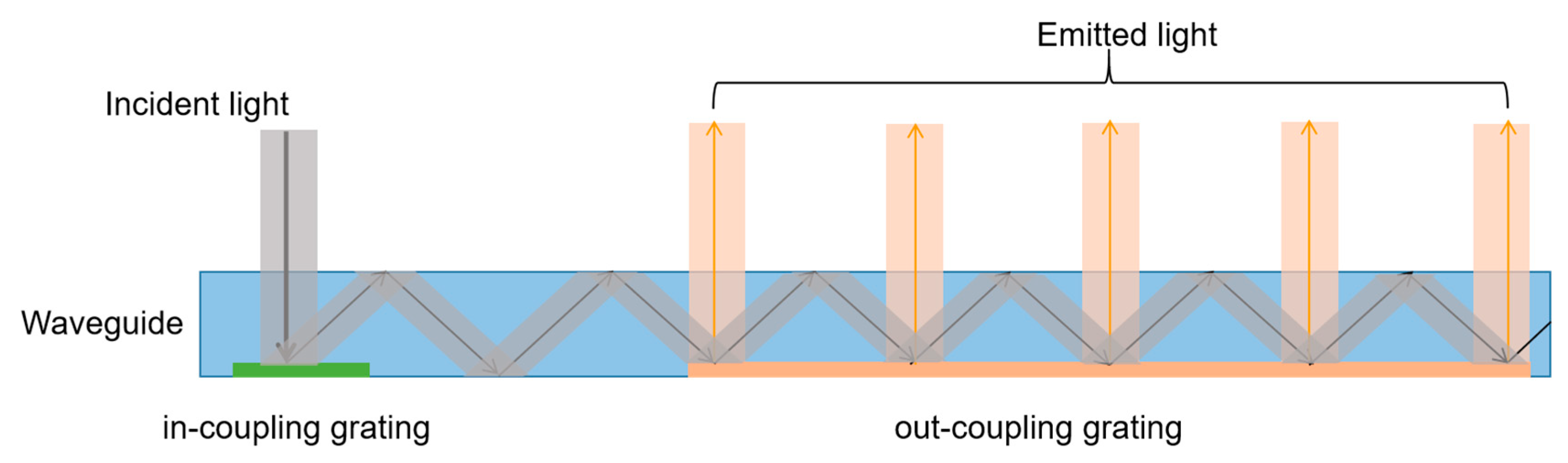
Taking the reflective diffraction waveguide as an example (the coupling element uses a reflective diffraction grating), it can be seen in Figure 1 that as the beam propagates within the waveguide, a portion of the light energy is diffracted and derivable each time after entering the in-coupling element, and the remaining light energy continues to be transmitted in the waveguide in total internal reflection until it again enters the out-coupling element and re-coupling occurs. In this way, the input beam will be continuously copied and coupled out on the outcoupling element, ultimately achieving an extended expansion.
As shown in Figure 1, only exit pupil one-dimensional expansion can be realized. In fact, a two-dimensional expansion structure can be designed to obtain a larger exit pupil size. Compared with the one-dimensional waveguide dilation structure, two-dimensional exit pupil expansion requires only one more coupling steering element to function as one-dimensional expansion in the other direction and plane steering for transmitting light in the waveguide. Nokia Research scientist Tapani Levolas summarized two possible two-dimensional expansion structures for diffractive waveguide coupling elements in his paper [15]. Both structures showed in that paper have three coupling elements as in-coupling, intermediate coupling, and out-coupling, respectively. The difference between the two structures is mainly reflected in the number of times the beam is coupled at the intermediate coupling. The three coupling elements in the structure where the light beam is even-numbered coupled at the intermediate coupling concentrate in a single direction, which does not satisfy the "glasses" shape requirement, as the other structure where the light beam is odd-numbered coupled at the intermediate coupling does. Therefore, the odd-numbered structure is selected as the expansion method described herein.
According to previous researches, polarization volume holographic gratings (PVG) can not only achieve high-efficiency single-order diffraction under Bragg conditions, but also have a larger wavelength bandwidth and angular bandwidth and show polarization sensitivity similar to Pancharatnam–Berry (PB) phase gratings [16,17,18,19]. Therefore, compared to traditional volume holographic gratings [20,21,22] and surface relief gratings [23,24,25], polarization volume holographic gratings are more suitable as the coupling element of the holographic waveguide system, and it is an extremely excellent solution to realize the holographic optical waveguide display technology. However, the current application of PVG is still focused on achieving a one-dimensional exit pupil, which has a small exit pupil size. Therefore, expanding the size of the exit pupil from one-dimensional (linear structure) to two-dimensional (planar structure) is a feasible way to expand the scope of the exit pupil.
This paper briefly reviews the structure of PVG and the calculation method of each grating in the two-dimensional pupil expansion structure, and then uses Zemax to establish a tracing model and obtain the simulation imaging results. Finally, a monochromatic waveguide structure with a two-dimensional pupil expansion effect is actually prepared.
2. Materials and Methods
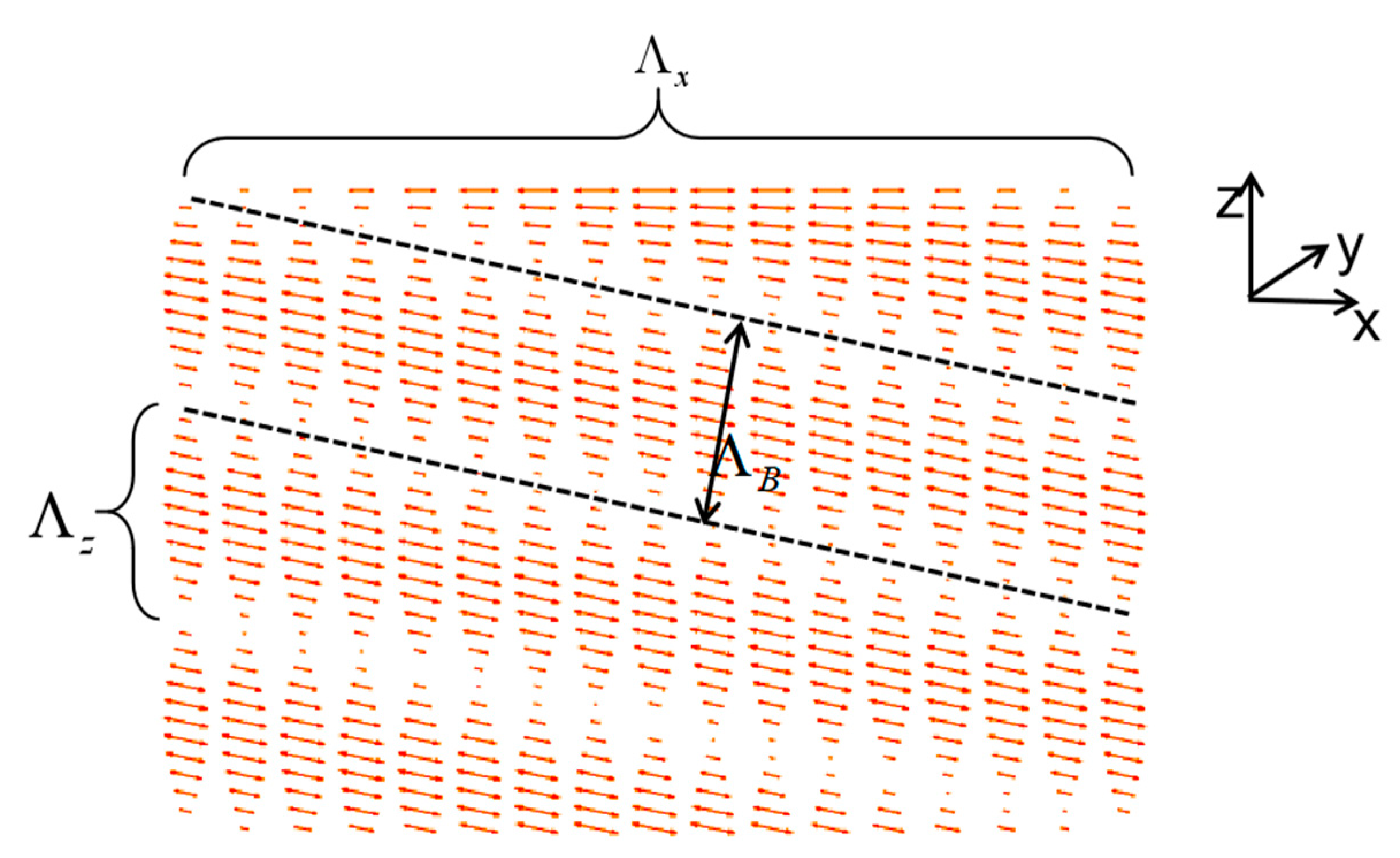
Unlike conventional volume holographic grating which utilizes the periodic variation of the refractive index of an isotropic medium to produce a Bragg effect [26], the PVG medium is anisotropic, and its periodic refractive index modulation is produced by periodic rotation of the molecular optical axis in the medium. In terms of diffraction characteristics, PVG can produce high-efficiency single-stage Bragg diffraction as volume holographic grating does, thus ensuring optical coupling efficiency and image transmission quality of the waveguide system. As an advantage, the response bandwidth of PVG is much larger than the response bandwidth of traditional volume holographic grating [27]. The narrow waveguide FOV caused by the small response bandwidth is the main problem faced by the current waveguide coupling technology based on volume holographic gratings. The proposal of PVG is conducive to the solution to this pain point problem. On the other hand, PVG also exhibits Pancharatnam–Berry (PB) phase polarization response characteristics not found in volume holographic grating [28]. This feature guarantees the see-through ability of the waveguide system under large FOV (wide response bandwidth) and adds a new design dimension to the waveguide coupling component. The optimization space and application method of the waveguide coupling element are expanded by using PVG. The basic grating structure of PVG is shown in Figure 2.
depicted in Figure 2 means the period of periodical refractive index planes, which should be calculated by the Bragg equation after determining the center wavelength.
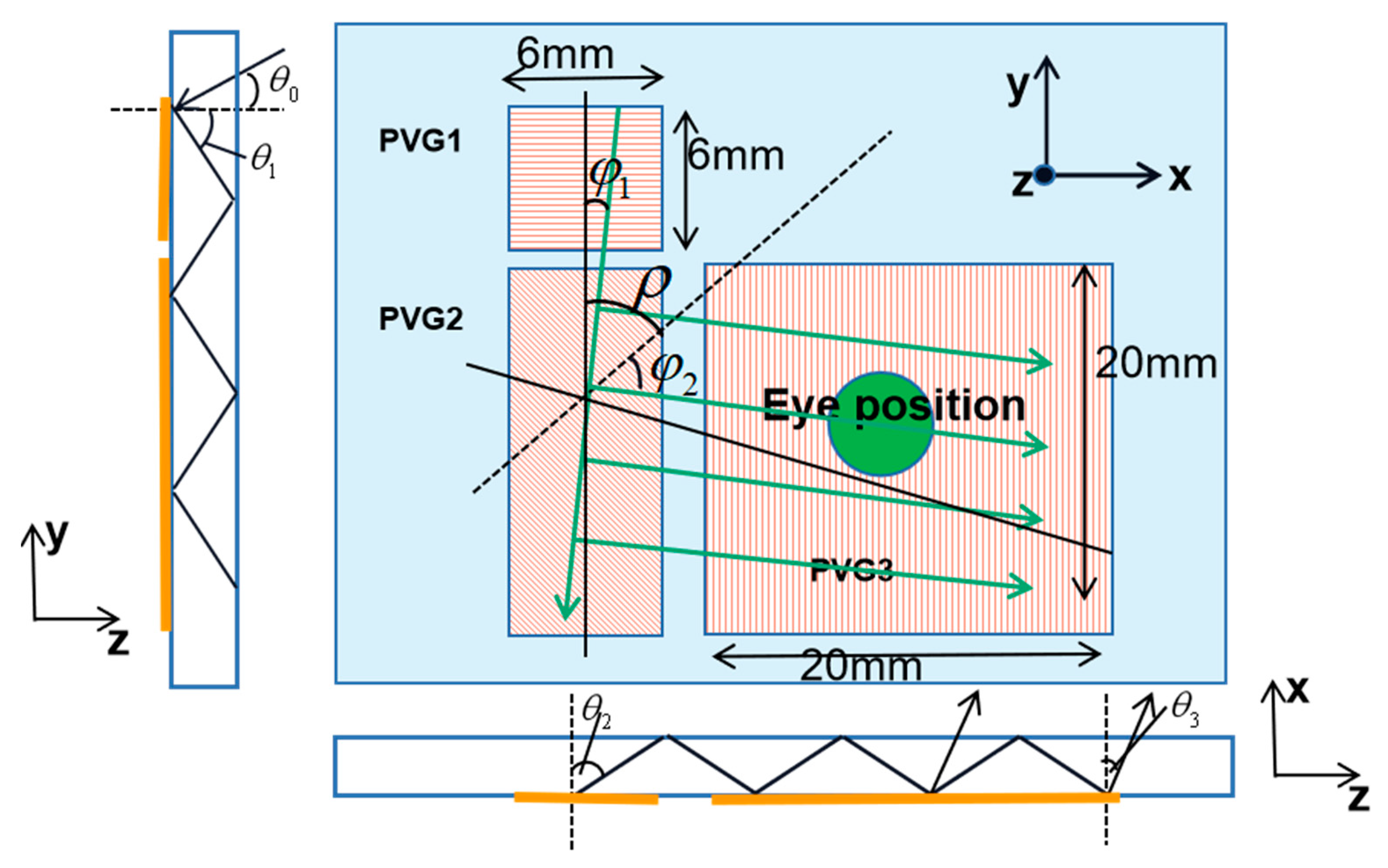
The structure of two-dimension exit pupil expansion is more complicated than one-dimension because of the extra intermediate grating so that the light can be expanded into both horizontal and vertical directions, further expanding the exit pupil size. Therefore, we need to introduce the calculation method in detail before we simulate the structure. Taking the structure in Figure 3 as an example, PVG1, PVG2, and PVG3 represent the in-coupling, intermediate, and out-coupling grating, respectively. The angle between incidence and the normal of PVG1 surface is , and the angle between incidence and the grating vector of PVG1 is . The angle between the light diffracted from PVG1 and the normal of PVG1 is , and the angle with the grating vector of PVG1 is , recording the direction as (). Similarly, the direction of the light diffracted from PVG2 and PVG3 can be recorded as () and (), respectively. The angles are depicted in Figure 3, which shows the left view and front view of the waveguide.
For the in-coupling grating PVG1, we decompose the incident light and first-order diffracted light in the direction of the grating vector and the direction perpendicular to the grating vector according to the grating formula, and we can obtain () and () satisfying the following formula,
where n is the average refractive index of the glass substrate, λ is the wavelength of the incident light in vacuum, and d is the period of the surface grating of PVG1 (d is actually equal to in Figure 2). In this paper, we set the surface period of the in- and out-coupling gratings as the same value to make the model structure simpler. Then, the surface period (written as ) of the intermediate grating PVG2 must satisfy the relationship (Equation (3)) to make sure that a combination of the three surface grating vectors has substantially zero magnitude, which can allow light to be coupled out of the waveguide in the same orientation as it was input. Advantageously, all wavelengths can experience the same, facilitating a color display.
where represents half of the angle between the normal of PVG1 and the normal of PVG3, as shown in Figure 3.
Decomposing the incident light and diffracted light of PVG2 in the direction of its grating vector and the direction perpendicular to the grating vector, it can be obtained that () and () satisfy the following formula,
Similarly, for the out-coupling grating PVG3, we can also get the () by the following formula,
It still needs to be considered the period of the grating vector of the three coupled gratings in the z-direction () when using PVGs as the coupling elements, which can be written as Equations (6)–(8). Through the calculation, the periods in the z-axis direction of the three PVGs can be obtained.
where , , and represent the component of the grating vector in the x, y, and z-axis, and represents the in-coupling grating, the intermediate grating, and the out-coupling grating, respectively; represents the volume grating vector; is the grating period shown in Figure 2.
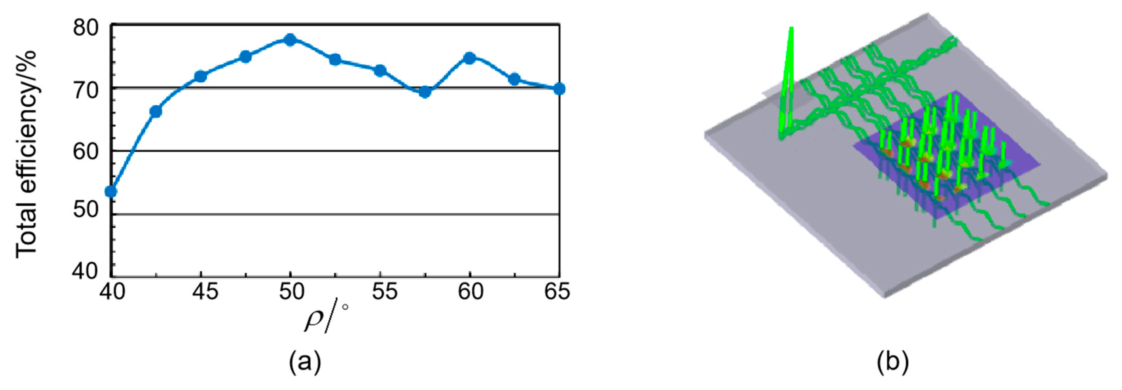
We can design the needed PVGs through the calculation of horizontal grating period length () and vertical grating period length () by the equations above after determining the value of . Therefore, we need to determine a proper value of . Figure 4a represents the variation curve of the total efficiency of the emitted light with . It can be seen from the curve that (1) when is small, the total energy utilization rate of the system is generally lower; (2) the total energy utilization rate curve of the outgoing light has two peaks, appearing at = 50° and = 60°, respectively, and the energy utilization rate will be slightly higher when = 50°. In this paper, three PVGs (in-coupling, intermediate coupling, and out-coupling, respectively) whose center wavelength is at 550 nm are presented in simulations and experiments, and the incident light is normal to the waveguide substrate. The propagation angle in the waveguide is set as 60° and is set as 50° in order to get the highest energy utilization rate.
The ray-tracing diagram in Zemax is shown in Figure 4. In this simulation model, the horizontal grating period length is set as 371 nm for the in-coupling (or out-coupling), and 288.5 nm for the intermediate coupling grating.
As described above, the light stream is coupled into the waveguide from the in-coupling grating, then propagates in the waveguide and reaches the intermediate, which extends the horizontal FOV. After that, the light propagates along the x-axis and reaches the out-coupling and is diffracted out the waveguide, which extends the vertical FOV.
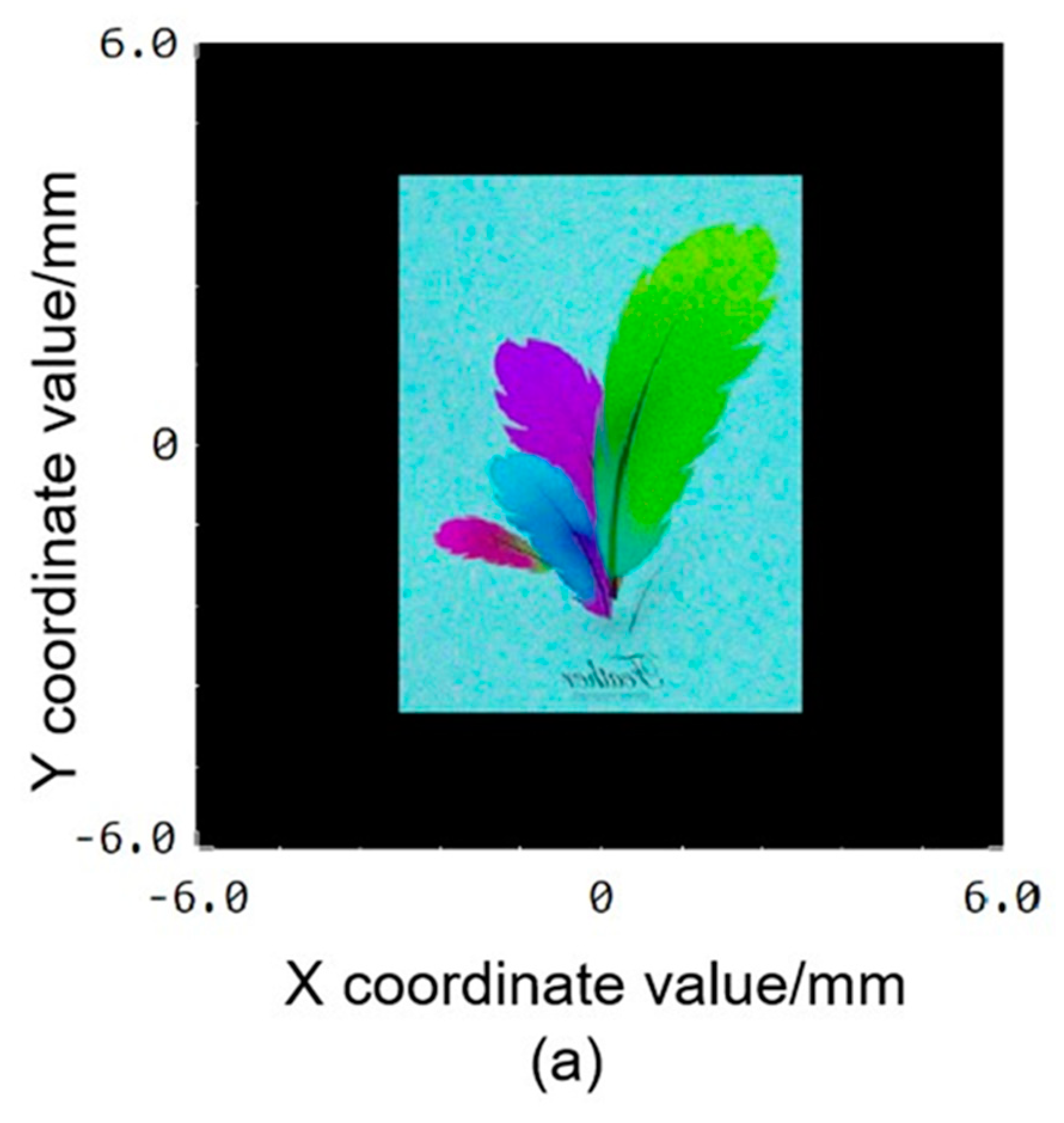
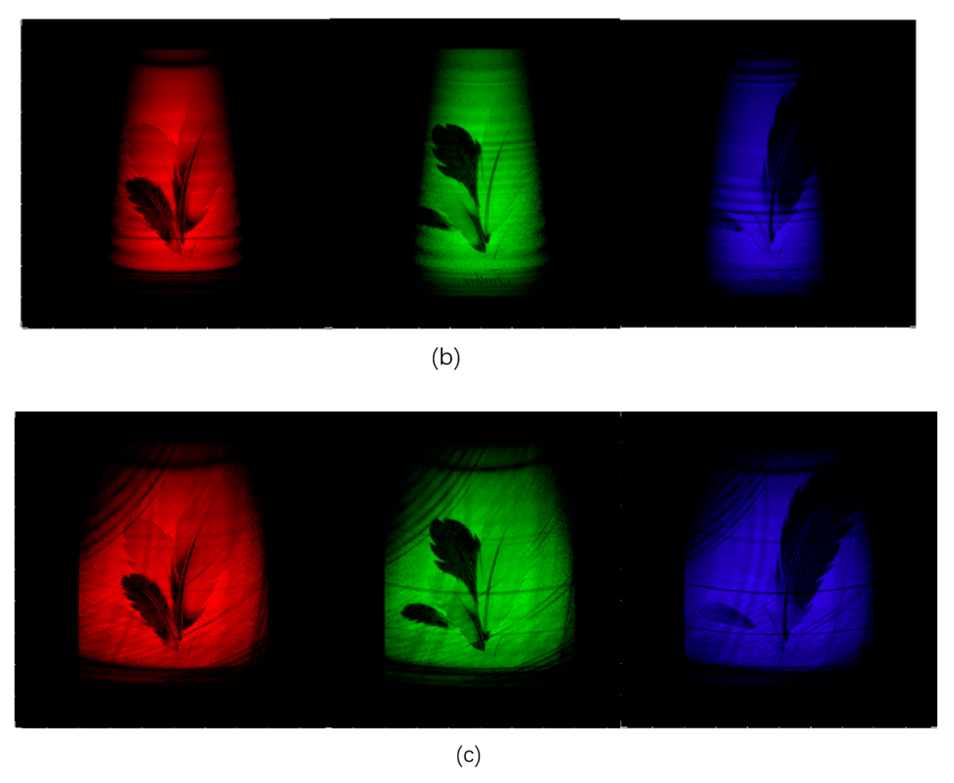
Figure 5 shows the micro-image source image used in the simulation and the one-dimensional pupil expansion effect of red, green, and blue as a comparison with two-dimensional pupil expansion.
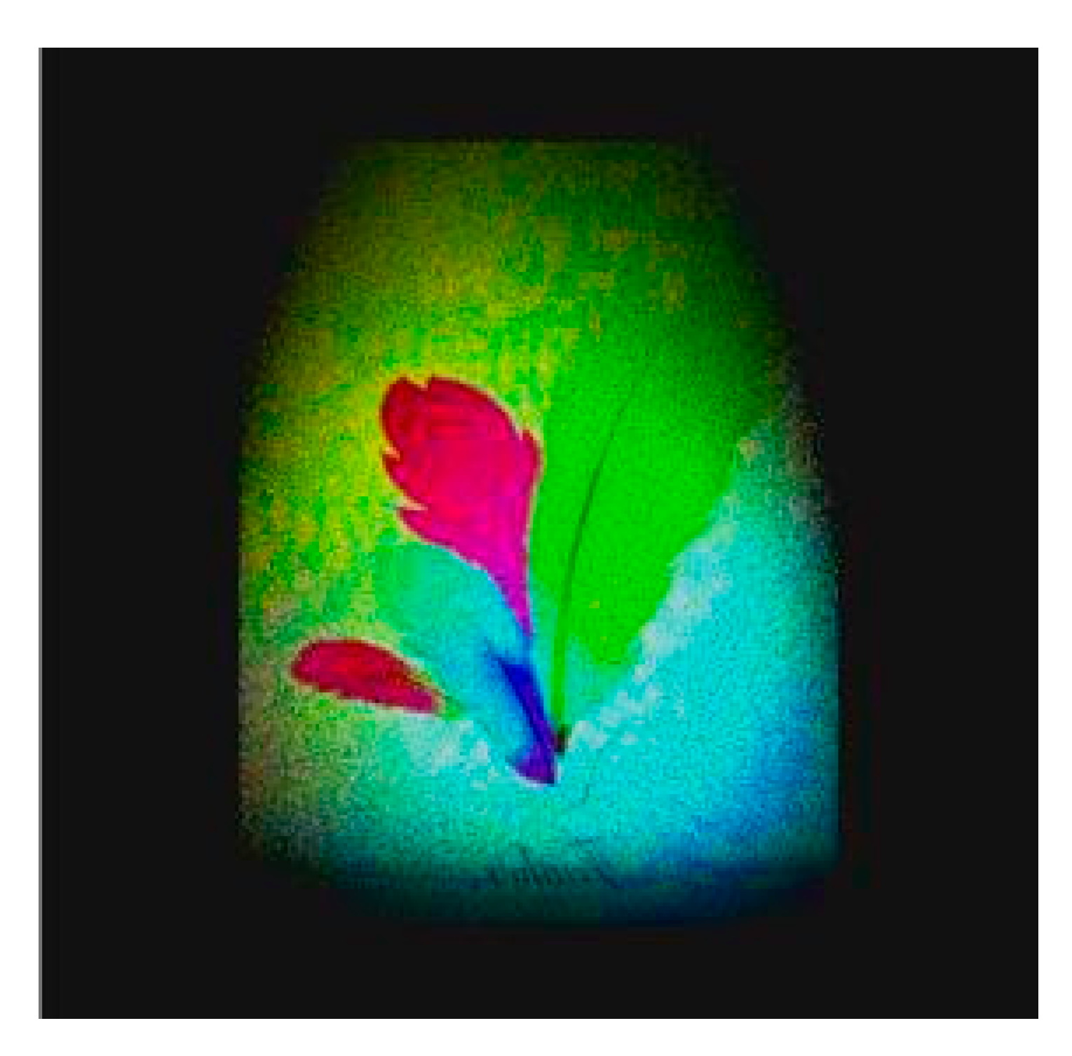
It can be seen from Figure 5 that, compared with one-dimension exit pupil, the two-dimension structure expands exit pupil in two directions. However, some dark lines appear at four corners in Figure 5c, which is actually because of the angle bandwidth limitation of the intermediate grating. This problem can be solved out by overlapping several gratings which have different angle bandwidth range to enlarge the total angle bandwidth. Besides, we can achieve the chromatic diffraction feature by superimposing two waveguides, as previous work did, because the propagation of RGB three-color light is independent of each other. The simulation result of the full-color display with a white light source is shown in Figure 6. It can be seen that the simulation results are also closer to the original picture.
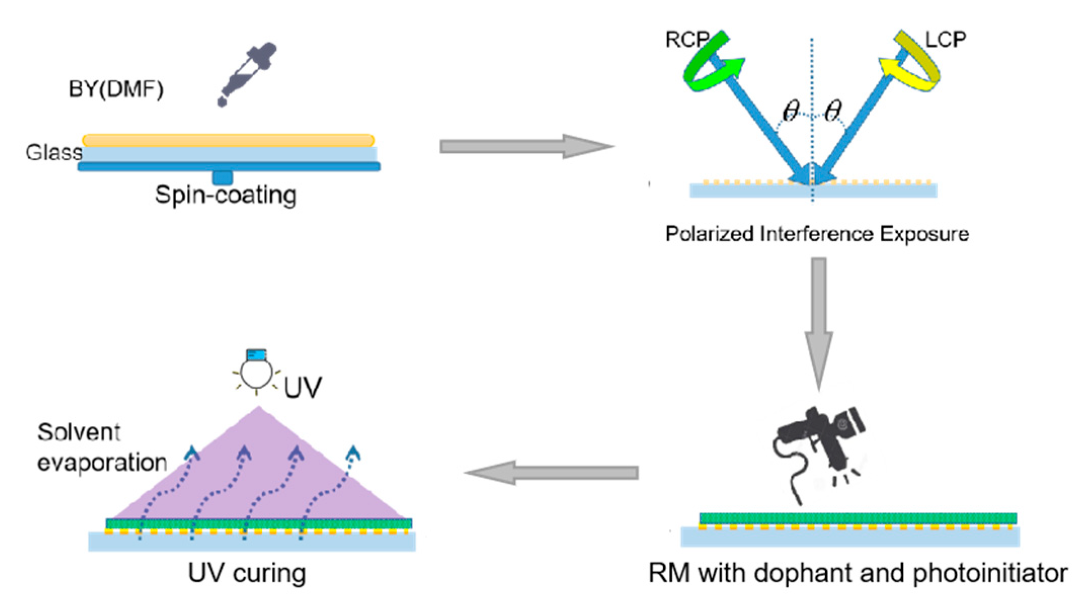
The PVGs in this work were fabricated using the following procedure. First, high index glass used as the substrate to get a larger field of view was cleaned by sonication in glass detergent, deionized water, and ethyl alcohol for 10 min in each solvent and then the substrate was cleaned by ultraviolet ozone for 15 min. Subsequently, we recorded a polarization volume grating on the photo-alignment material; then we used a mixture of chiral liquid crystal and prepolymer to cover and be oriented by the formerly prepared layer in order to get a 2D periodical structure (as depicted in Figure 2); finally, this structure was frozen by the UV curing process. A more detailed preparation process is shown in Figure 7.
The first step was to spin-coat the photo-alignment material. Brilliant yellow (BY) was selected as the photo-alignment material [29] and in the experiment, 0.06 g BY dissolved in 9.94 g DMF was an appropriate proportion. BY was spin-coated on cleaned glass waveguide substrate at 500 rpm for 5 s and then 3000 rpm for 30 s to obtain uniform films. For the second step, the glass coated with the photo-alignment material was placed in the optical path and then was exposed to the opposite circularly polarized light by two beams. In our experiment, a 457 nm laser was used as the recording light. Two opposite-handed circularly polarized beams were overlapped on the sample with a certain angle to generate the polarized interference patterns recorded in the BY film. It is worth noting that we needed to expose three (in-coupling, intermediate, and out-coupling) gratings at once by rotating the glass substrate. The in-coupling grating was first exposed, and then the glass substrate was rotated counterclockwise by 50° to obtain an intermediate coupling grating, and finally, the glass substrate was rotated counterclockwise by 50° again to expose the out-coupling grating. For in-coupling grating (or out-coupling grating) and intermediate coupling grating PVGs, the half of exposure angle was set as 38° and 72.3°, respectively, to achieve the desired different horizontal periods. The third step was to prepare the liquid crystal layer. The liquid crystal material was then sprayed with a spray gun to the position of the three gratings. The reason for choosing spraying is that (1) the concentration of the liquid crystal material solution required for different gratings is different, and different gratings can be distinguished by spraying; (2) compared with the spin coating method, the surface of the grating obtained by spraying is flatter. In this paper, the RM257 (ne = 1.678, no = 1.508 at 550 nm) with chiral dopant R5011 and Irgacure 651 were used as the chiral twist liquid crystal (LC) polymer precursor and the photoinitiator, respectively. Toluene was employed as a solvent to dissolve all the solute materials after oscillation with a proportion of 1:8. The mass fractions of each solute material for proposed PVGs (taking green for example) are listed in Table 1. The fourth step was to UV-cure the spin-coated glass substrate.
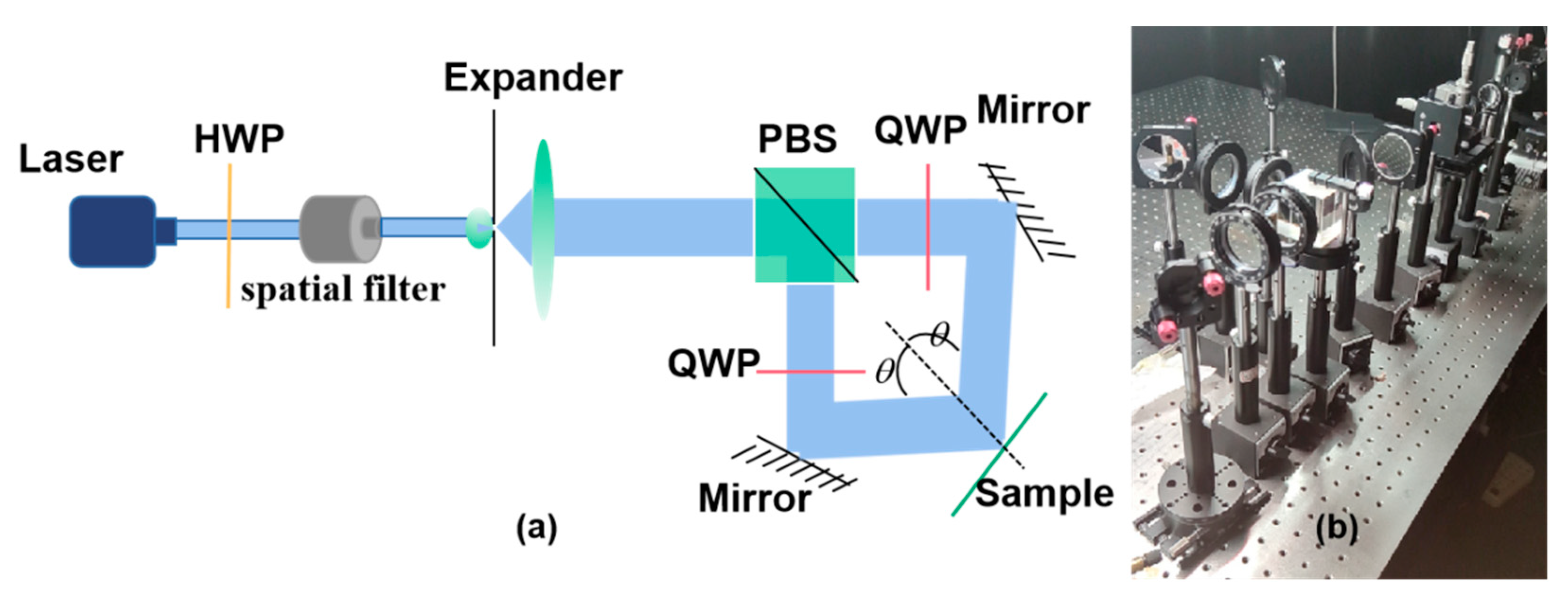
The optical setup, including schematic light path diagram and real light path we used, is shown in Figure 8. The intensity of each path beam for interference was equal, and the exposure dosage was 1 J/cm2. After the light beam is emitted from the laser, it first passes through the first half-wave plate. The function of this half-wave plate is to control the light intensity ratio of the two orthogonally polarized P waves and S waves that are split by the following PBS. This is because in the final exposure, it is necessary to control the two coherent polarized lights with different rotation directions to have the same light intensity, so that a clearer polarization pattern can be obtained, so it is very necessary to place a half-wave plate in front of the PBS. Then, the beam is filtered through a spatial filter. The spatial filter plays a filtering role to obtain a more ideal Gaussian beam, so as to make the most central part of the Gaussian beam as large as possible. The beam is then expanded by a beam expander. The beam expander is composed of a small hole and a double cemented lens, which can complete the beam expansion and collimation of the beam. In the actual experimental operation, the beam diameter after beam expansion can reach 2~3 cm. After the expanded beam is split by the PBS, a P wave and an S wave are formed respectively, and the intensity of the two beams is the same. The quarter-wave plate converts the two linearly polarized beams into left-handed circularly polarized light and right-handed circularly polarized light, respectively.
3. Results and Discussion
The desired vertical periodical periods for each PVG were generated after the spray-coating of prepared chiral dopant solutions until sufficient thickness (> 4.5 μm). As a result, the molecules of birefringent materials formed an inclined helical structure, provided by the anchoring power of photoalignment layers and helix twist power of chiral dopant to produce the designed two-dimensional periodic structure after the partial evaporation of the solvent. The coated substrate was then cured with 365 nm UV light at a dosage of 5 J/cm2 in a nitrogen environment. The glass substrates used here have a rectangular shape (30 mm × 30 mm) with a thickness of 1 mm, and the refractive index is 1.8.
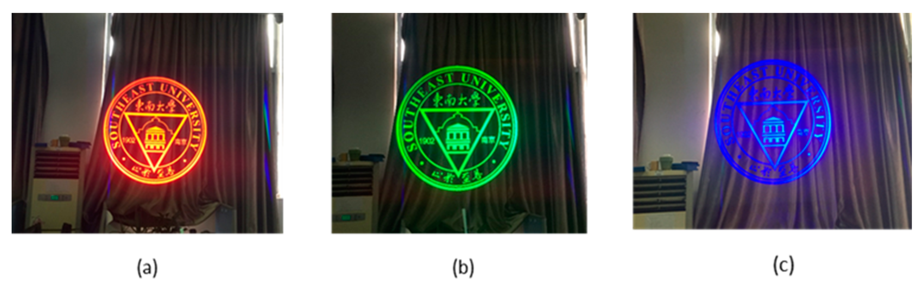
The imaging effects of red, green, and blue are shown in Figure 9. A colorful image was used as the example input, and a monochromatic light source (red, green, and blue, respectively) was used. A camera was placed in front of the out-coupler with a designed eye-relief of 18 mm to capture the output image. The image within the range of 35° diagonal FOV was fully and clearly observed without significant color shift or distortion. The size of the exit pupil was measured to be 18 mm long and 17 mm wide. In fact, the exit pupil size can be enlarged more by using a larger out-coupler.
The optical efficiency of the proposed system was measured. The input luminous flux of a full white image was measured as 77.3 lm, and output luminance was 9142 (nit)cd∕m2, which corresponds to an efficiency of 118.3 nit/lm per lumen. We also measured efficiency for three primary color images, and got 121.0 nit/lm, 132.4 nit/lm, and 96.7 nit/lm per lumen for red, green, and blue images, respectively. Meanwhile, we measured the light luminance from a D65 light source before and passing through the out-couplers area and obtained a 72% transmittance, which indicates good transparency for the ambient light.
4. Conclusions
In summary, we demonstrated a two-dimensional exit pupil expansion structure based on PVG for a waveguide display system. The proposed PVG couplers have a two-dimensional anisotropic periodic structure and present a unique highly efficient single-order Bragg diffraction with polarized selectivity. We employed the scheme of multiple PVG layers to achieve the chromatic diffraction features for PVG couplers and designed the matching double-layer waveguide structure to realize a full-color near-eye display by Zemax. The polarized interference exposure with photo-alignment methods was utilized to fabricate the proposed PVG and the prepared PVG couplers exhibited over 70% diffraction efficiency with large diffraction angles at spectra of blue, green, and red. We also demonstrated a prototype to validate the monochromatic-color display function of our designs, and the results showed that a clear full-color display with a diagonal FOV of around 35° and an exit pupil of 18 mm long and 17 mm wide was achieved. The overall optical efficiency was measured as high as 118.3 nit/lm per lumen with a transparency of 72% for ambient light. This work makes the PVG with the proposed waveguide structure a promising candidate for AR applications with two-dimension exit pupil expansion.
Author Contributions
Conceptualization, J.C. and Y.Z.; methodology, J.C.; software, J.C.; validation, J.C. and Y.Z.; writing—original draft preparation, J.C.; writing—review and editing, J.C. and Y.Z. All authors have read and agreed to the published version of the manuscript.
Funding
This research received no external funding.
Institutional Review Board Statement
Not applicable.
Informed Consent Statement
Not applicable.
Data Availability Statement
Data is contained within the article.
Acknowledgments
We would like to express our sincere appreciations to the anonymous referee for valuable suggestions and corrections.
Conflicts of Interest
The authors declare no conflict of interest.
References
- Urey, H. Diffractive exit-pupil expander for display applications. Appl. Opt. 2001, 40, 5840–5851. [Google Scholar] [CrossRef] [PubMed]
- Powell, K.; Urey, H. Novel approach to exit pupil expansion for wearable displays. In Helmet-and Head-Mounted Displays; SPIE: Bellingham, WA, USA, 2002; pp. 235–248. [Google Scholar]
- Saarikko, P. Diffractive exit-pupil expander with a large field of view. In Photonics in Multimedia II; SPIE: Bellingham, WA, USA, 2008; p. 700105. [Google Scholar]
- Urey, H.; Powell, K. Microlens array-based exit pupil expander for full-color display applications. In Photon Management; SPIE: Bellingham, WA, USA, 2004; pp. 227–236. [Google Scholar]
- Bigler, C.M.; Mann, M.S.; Blanche, P.-A. Holographic waveguide HUD with in-line pupil expansion and 2D FOV expansion. Appl. Opt. 2019, 58, G326–G331. [Google Scholar] [CrossRef]
- Äyräs, P.; Saarikko, P.; Levola, T. Exit pupil expander with a large field of view based on diffractive optics. J. Soc. Inf. Disp. 2009, 17, 659–664. [Google Scholar] [CrossRef]
- Park, S.-G.; Miranda, M.; Hong, J.-Y.; Kim, Y.; Lee, B. (Eds.) Expansion of an exit pupil of the projection lens in a multi-projection 3D system. In Imaging and Applied Optics; Optical Society of America: Seattle, WA, USA, 2014. [Google Scholar]
- Kim, M.; Lim, S.; Choi, G.; Kim, Y.; Kim, H.; Hahn, J. Expanded Exit-Pupil Holographic Head-Mounted Display With High-Speed Digital Micromirror Device. ETRI J. 2018, 40, 366–375. [Google Scholar] [CrossRef] [Green Version]
- Li, M.; Wang, L.; Shen, W.; Wu, D.; Bai, Y. Microlens array expander with an improved light intensity distribution throughperiodic submicro-scale filling for near-eye displays. Appl. Opt. 2018, 57, 1026–1036. [Google Scholar] [CrossRef] [PubMed]
- Hedili, M.K.; Freeman, M.O.; Urey, H. Microlens array-based high-gain screen design for direct projection head-up displays. Appl. Opt. 2013, 52, 1351–1357. [Google Scholar] [CrossRef] [PubMed] [Green Version]
- Kress, B.; Raulot, V.; Grossman, M. Exit pupil expander for wearable see-through displays. In Photonic Applications for Aerospace, Transportation, and Harsh Environment III; SPIE: Bellingham, WA, USA, 2012; p. 83680D. [Google Scholar]
- He, Y.; Xi, H.; Chen, Q.; Wu, F.; Li, C.; Zhu, X.; Song, W. Analysis of adjustment error in aspheric null testing with CGH. In Proceedings of the Eighth International Symposium on Advanced Optical Manufacturing and Testing Technology (AOMATT2016), Suzhou, China, 26–29 April 2016. [Google Scholar]
- Cakmakci, O.; Rolland, J. Head-worn displays: A review. J. Disp. Technol. 2006, 2, 199–216. [Google Scholar] [CrossRef]
- Cameron, A. Optical waveguide technology and its application in head-mounted displays. In Display Technologies and Applications for Defense, Security, and Avionics VI; SPIE Defense, Security, and Sensing; SPIE: Bellingham, WA, USA, 2012; p. 83830E. [Google Scholar]
- Levola, T. Diffractive optics for virtual reality displays. J. Soc. Inf. Disp. 2006, 14, 467–475. [Google Scholar] [CrossRef]
- Bomzon, Z.; Kleiner, V.; Hasman, E. Pancharatnam–Berry phase in space-variant polarization-state manipulations with subwavelength gratings. Opt. Lett. 2001, 26, 1424–1426. [Google Scholar] [CrossRef] [PubMed]
- Liu, Y.; Ke, Y.; Zhou, J.; Liu, Y.; Luo, H.; Wen, S.; Fan, D. Generation of perfect vortex and vector beams based on Pancharatnam-Berry phase elements. Sci. Rep. 2017, 7, 44096. [Google Scholar] [CrossRef] [PubMed] [Green Version]
- Fu, W.; Zhou, Y.; Yuan, Y.; Lin, T.; Zhou, Y.; Huang, H.; Fan, F.; Wen, S. Generalization of Pancharatnam-Berry phase interference theory for fabricating phase-integrated liquid crystal optical elements. Liq. Cryst. 2020, 47, 369–376. [Google Scholar] [CrossRef]
- Stebryte, M.; Nys, I.; Ussembayev, Y.Y.; Beeckman, J.; Neyts, K. Large Angle Forward Diffraction by Chiral Liquid Crystal Gratings with Inclined Helical Axis. Crystals 2020, 10, 807. [Google Scholar] [CrossRef]
- Barden Samuel, C.; Arns James, A.; Colburn Willis, S.; Williams Joel, B. Volume-Phase Holographic Gratings and the Efficiency of Three Simple Volume-Phase Holographic Gratings. Publ. Astron. Soc. Pac. 2000, 112, 809–820. [Google Scholar] [CrossRef] [Green Version]
- Zhang, W.; Bian, S.; Kim, S.I.; Kuzyk, M.G. High-efficiency holographic volume index gratings in DR1-dye-doped poly(methyl methacrylate). Opt. Lett. 2002, 27, 1105–1107. [Google Scholar] [CrossRef] [PubMed]
- Bianco, G.; Ferrara, M.A.; Borbone, F.; Roviello, A.; Pagliarulo, V.; Grilli, S.; Ferraro, P.; Striano, V.; Coppola, G. Volume holographic gratings: Fabrication and characterization. In Holography: Advances and Modern Trends IV; SPIE: Bellingham, WA, USA, 2015; p. 950807. [Google Scholar]
- Moharam, M.G.; Gaylord, T.K. Diffraction analysis of dielectric surface-relief gratings. J Opt. Soc. Am. 1982, 72, 1385–1392. [Google Scholar] [CrossRef]
- Levola, T.; Aaltonen, V. Near-to-eye display with diffractive exit pupil expander having chevron design. J. Soc. Inf. Disp. 2008, 16, 857–862. [Google Scholar] [CrossRef]
- Moujdi, S.; Rahmouni, A.; Mahfoud, T.; Nesterenko, D.V.; Halim, M.; Sekkat, Z. Surface relief gratings in azo-polymers revisited. J. Appl. Phys. 2018, 124, 213103. [Google Scholar] [CrossRef]
- Shen, Z.; Zhang, Y.; Weng, Y.; Li, X. Characterization and Optimization of Field of View in a Holographic Waveguide Display. IEEE Photon. J. 2017, 9, 1–11. [Google Scholar] [CrossRef]
- Weng, Y.; Zhang, Y.; Cui, J.; Liu, A.; Shen, Z.; Li, X.; Wang, B. Liquid-crystal-based polarization volume grating applied for full-color waveguide displays. Opt. Lett. 2018, 43, 5773–5776. [Google Scholar] [CrossRef]
- Chen, R.; Lee, Y.-H.; Zhan, T.; Yin, K.; An, Z.; Wu, S.-T. Multistimuli-Responsive Self-Organized Liquid Crystal Bragg Gratings. Adv. Opt. Mater. 2019, 7, 1900101. [Google Scholar] [CrossRef]
- Shi, Y.; Zhao, C.; Ho, J.Y.-L.; Song, F.; Chigrinov, V.G.; Luo, D.; Kwok, H.-S.; Sun, X.W. High Photoinduced Ordering and Controllable Photostability of Hydrophilic Azobenzene Material Based on Relative Humidity. Langmuir 2018, 34, 4465–4472. [Google Scholar] [CrossRef] [PubMed]
Figure 1.
Optical waveguide one-dimensional exit pupil expansion schematic.

Figure 2.
The grating structure of polarization volume holographic gratings (PVG). PVG has a period of in x–y plane and a period of in z-axis direction. Periodical refractive index planes have a period of .
Figure 2.
The grating structure of polarization volume holographic gratings (PVG). PVG has a period of in x–y plane and a period of in z-axis direction. Periodical refractive index planes have a period of .

Figure 3.
Schematic diagram of two-dimensional exit pupil expansion structure.

Figure 4.
(a) The variation curve of the total efficiency of the emitted light with ; (b) ray tracing diagram of a two-dimensional expansion holographic waveguide.
Figure 4.
(a) The variation curve of the total efficiency of the emitted light with ; (b) ray tracing diagram of a two-dimensional expansion holographic waveguide.

Figure 5.
(a) The micro-image source image; (b) the one-dimension exit pupil effect of red, green, and blue; (c) the two-dimension exit pupil effect of red, green, and blue.
Figure 5.
(a) The micro-image source image; (b) the one-dimension exit pupil effect of red, green, and blue; (c) the two-dimension exit pupil effect of red, green, and blue.


Figure 6.
Two-dimensional pupil expansion simulation results when white light is incident.

Figure 7.
The fabrication process of PVG.

Figure 8.
The optical setup: (a) the schematic light path diagram; (b) the real light path.

Figure 9.
Photograph of the output image of the proposed waveguide near-eye display system. (a) red image; (b) green image; (c) blue image.
Figure 9.
Photograph of the output image of the proposed waveguide near-eye display system. (a) red image; (b) green image; (c) blue image.


Table 1.
The mass fractions of each solute material for proposed PVGs.
| PVGs | RM257 | R5011 | Irgacure651 |
|---|---|---|---|
| In/out-coupling PVG | 0.8310 g | 0.0200 g | 0.0437 g |
| Intermediate coupling PVG | 1.2564 g | 0.0200 g | 0.0661 g |
Publisher’s Note: MDPI stays neutral with regard to jurisdictional claims in published maps and institutional affiliations. |
© 2021 by the authors. Licensee MDPI, Basel, Switzerland. This article is an open access article distributed under the terms and conditions of the Creative Commons Attribution (CC BY) license (http://creativecommons.org/licenses/by/4.0/).
Share and Cite
MDPI and ACS Style
Cui, J.; Zhang, Y. Exit Pupil Expansion Based on Polarization Volume Grating. Crystals 2021, 11, 333. https://doi.org/10.3390/cryst11040333
AMA Style
Cui J, Zhang Y. Exit Pupil Expansion Based on Polarization Volume Grating. Crystals. 2021; 11(4):333. https://doi.org/10.3390/cryst11040333
Chicago/Turabian StyleCui, Jingyi, and Yuning Zhang. 2021. "Exit Pupil Expansion Based on Polarization Volume Grating" Crystals 11, no. 4: 333. https://doi.org/10.3390/cryst11040333
Note that from the first issue of 2016, this journal uses article numbers instead of page numbers. See further details here.