
Recent Advances in Photoalignment Liquid Crystal Polarization Gratings and Their Applications

Key Laboratory for Micro/Nano Optoelectronic Devices of Ministry of Education & Hunan Provincial Key Laboratory of Low-Dimensional Structural Physics and Devices, School of Physics and Electronics, Hunan University, Changsha 410082, China
*
Author to whom correspondence should be addressed.
Crystals 2021, 11(8), 900; https://doi.org/10.3390/cryst11080900
Submission received: 3 June 2021
/
Revised: 22 July 2021
/
Accepted: 29 July 2021
/
Published: 31 July 2021
(This article belongs to the Special Issue Liquid-Crystal Polarization Gratings)
Abstract
:Liquid crystal (LC) circular polarization gratings (PGs), also known as Pancharatnam–Berry (PB) phase deflectors, are diffractive waveplates with linearly changed optical anisotropy axes. Due to the high diffraction efficiency, polarization selectivity character, and simple fabrication process, photoalignment LC PGs have been widely studied and developed especially in polarization management and beam split. In this review paper, we analyze the physical principles, show the exposure methods and fabrication process, and present relevant promising applications in photonics and imaging optics.
1. Introduction
Unlike the conventional diffraction gratings that periodically operate the amplitude or dynamical phase of light, polarization gratings (PGs) periodically modulate the polarization states or PB phases of light by spatially changing the anisotropy parameters across the plane of the elements in a periodic way [1]. Various anisotropic materials have been proposed and demonstrated to fabricate PG, such as liquid crystals (LCs) [2], plasmonics [3], dielectric metasurfaces [4,5], or space-variant polarizers [6], etc. Among them, LC PGs, as diffractive optical elements with an anisotropic periodic index profile using liquid crystal materials, play a prominent part due to their easy fabrication process, unique optical properties, and potential applications [7]. Many types of LC PGs have been reported [8,9]. As one of the most popular types of LC PGs, LC circular PGs have an anisotropic profile consisting of a spiraling, constant magnitude, and linear birefringence but are constant along the thickness [10,11]. In this review paper, we only discuss and review the most studied LC PGs: LC circular PGs, because LC circular PGs have received great attention owing to its 100% first-order diffraction efficiency and the polarization-selectivity characteristic [11].
In order to fabricate PGs with high quality and good performance, the LC anisotropic axes should be precisely aligned through exposing the photoalignment materials under a desired polarized field. Hence, polarization holographic recording has been regarded as a crucial step for LC PG fabrication. To date, various approaches have been applied for polarization hologram generation. Generally, they can be divided into three groups: interference [12,13], imprint [14,15,16,17], and digital approaches [18,19,20]. Based on the photoalignment technology, the most widely used PGs are fabricated into reactive mesogen polymer films [11] or electrically responsive LC cell [21]. In recent years, various PG-based applications have emerged due to the obvious advantages of PG, such as beam steering [22], integrated photonics devices [23], image processing [24], near eye display systems [13,25], etc.
In this paper, some recent advances in LC PG and their applications in optical systems have been reviewed. In Section 2, we analyze the basic operation principle of LC PG. In Section 3, the photoalignment technology and some polarization holography setup for alignment is introduced. The exposure methods for multi-domain PG are also reviewed in this part. The basic fabrication process of LC PG-based devices is described. In Section 4, we review some PG-based integrated photonic devices for structured light generation and manipulation, beam steering and edge detection systems for information processing, and some applications in imaging optics and displays.
2. Operation Principles
A large period LC PG in Raman–Nath regime is based on the PB phase of patterned LC wave plate [13]. The theoretical properties of PB phase optical elements can be explored by using the Jones Calculus. Based on the Jones Calculus method, when a wave plate with phase retardation and local direction of slow axis is illuminated by a left/right circular polarization light formulated as , the Jones vector of the output beam can be expressed as:
Here, the phase retardation , where is the birefringence of LC, is the thickness of LC layer, and is the wavelength of incident light. As for a half wave plate (HWP) with , the corresponding output beam is , manifesting that the handedness of circular polarization is reversed, and at the same time, an additional PB phase shift with is generated [26,27]. Its response to left-handed circular polarization (LCP) light and right-handed circular polarization (RCP) light is symmetric [7]. Here, Jones Calculus is the adequate way to describe the completely polarized light or the coherent superposition of polarized light because it operates the amplitudes or phases of light. The most appropriate analysis method is to use Mueller Calculus in terms of unpolarized or partially polarized light, because Stokes vectors and Mueller matrices operate on intensities [28].
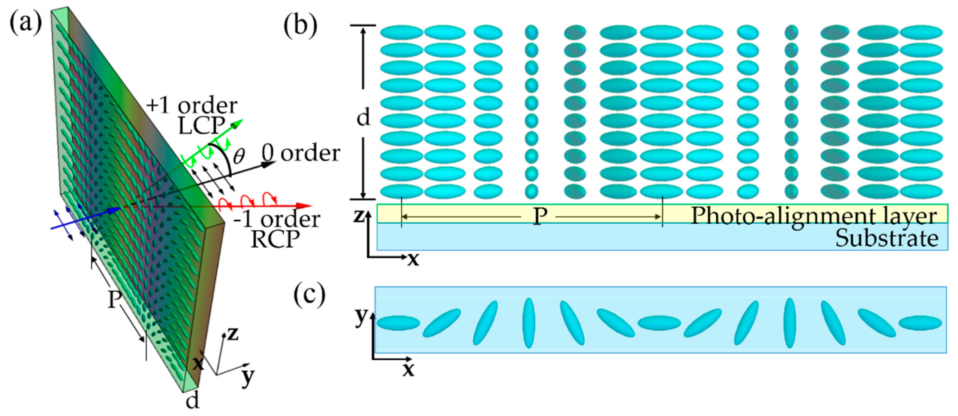
The molecular orientation of LC PG is depicted in Figure 1. The slow axis rotates along x-axis with an angle and the period is the length where the slow axis rotates by . To investigate the diffraction behavior of such a grating in the paraxial domain, the far-field electric field of the diffraction order after the Fourier transformation can be calculated as:
where is the period of PG and the local Jones matrix can be given by:
where is the rotation matrix. We can simplify Equation (2) as: , where the grating transfer matrix is: . The transfer matrix of a PG has the non-zero solutions for and orders, which are expressed as:
The diffraction efficiency of each order can be formulated as: , which is , , where is the normalized Stokes parameter related to the ellipticity of input light. Here, the optical properties of the PG are summarized, as seen in Figure 1a. Firstly, only and orders exist and the total efficiency is 100%. The and orders are left- and right-handed circular polarization, respectively. The diffraction angle of orders is at normal incidence, where is the wavelength of incident light. Secondly, order preserves the polarization state and the efficiency is determined by the phase retardation. In order to depict the LC PG structure in detail, the front view and top view of PG structure can be seen in Figure 1b,c.
In addition, one important issue in LC PG is that 100% first-order diffraction efficiency can only be achieved at a single wavelength at normal incidence under half wave retardation condition. To solve this issue, the twisted structures in polymer films are designed for realizing high efficiency in a broader spectral and angular bandwidth, extending LC PGs into more practical applications [29,30]. Here, the diffraction properties analyzed above were done using the paraxial approximation of waves propagation at small diffraction angles relative to the propagation axis [31]. If the period of PGs gets smaller () corresponding to a larger diffraction angle, the grating performs in the Bragg regime. A highly twisted structures [32,33] or slanted structures [34] is usually introduced in transmissive Bragg PG to keep high efficiency at normal incidence while its response to LCP and RCP is asymmetric [35]. Recently, reflective-type Bragg PG is also proposed using cholesteric LC [36,37,38,39]. These PGs with different structures are analyzed and reviewed by Zhang et al. [40] and the coupled-wave approach of Kogelnik [41,42] or rigorous coupled-wave analysis method [35,43,44,45] can be used to analyze the LC PG in Bragg regime [46].
3. Device Fabrication
3.1. LC Alignment
LC alignment technology is essential for planar patterned LC optical elements. Nowadays, several techniques are proposed for LC alignment such as micro-nano rubbing [47,48], direct-laser writing [49,50], and photoalignment [51,52,53,54]. Rubbing technique is considered to be a mature technique for most of LC displays, but micro-nano rubbing for LC PGs are low-resolution and the generation of electrostatic charges will bring damages to alignment layer. Direct-laser writing can also produce LC PG surface alignment, but the multi-step alignment procedure is time-consuming and complicated. LC photoalignment has been studied since 1988 [55] providing an easy way to control the direction of LC molecules. The photoalignment method is divided into two techniques: surface photoalignment and bulk alignment. The surface photoalignment are most widely used to create LC PGs with periods larger than . Bulk photoalignment of an LC polymer exhibits the obvious advantages especially in generating the symmetric and slanted PGs with periods smaller than 1um with large diffraction angle [34].
3.1.1. Surface Photoalignment
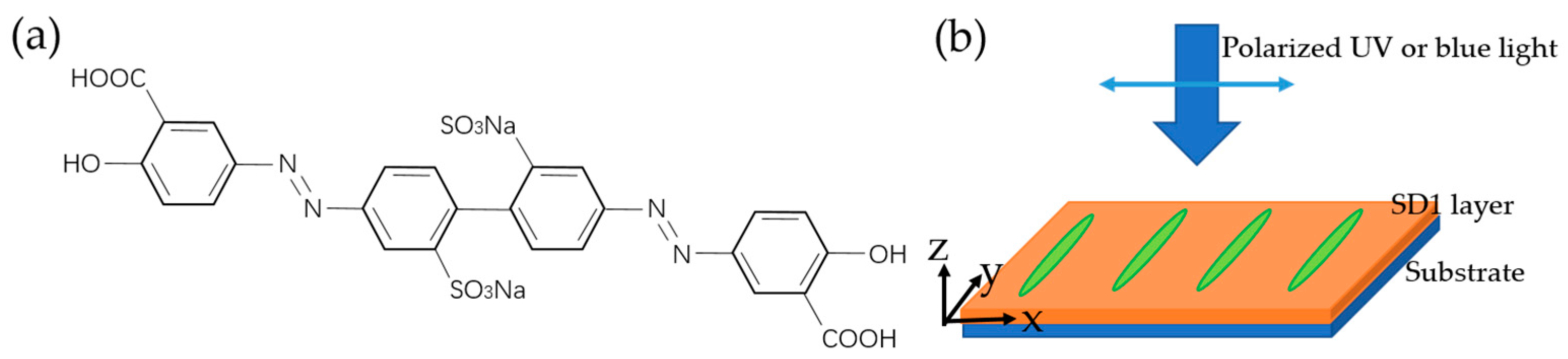
Photoalignment materials are sensitive to the polarization of exposed light and the effect of LC photoalignment is a direct consequence of the photo-induced optical anisotropy and dichroic absorption in the thin amorphous films, which is induced after exposure to ultraviolet (UV) or blue polarized light. Currently, the sulfuric azo dye SD1 [56] is widely used as photoalignment materials of LC PGs because of their extraordinary strong anchoring force and high photo- and thermal- stability. The mechanism of SD1 is photochemical reversible cis-trans isomerization under the action of UV-visible light [51]. The chemical structure of SD1 is shown in Figure 2a.
In the experiment, SD1 is dissolved in the solvent dimethylformamide (DMF) in 0.5–1% by weight. The solution was spin coated on the substrate at speed of 800 rpm for 10 s and then 1500 rpm for 30 s. Next, the substrate is baked for 5 min at to form a thin photoalignment layer. As shown in Figure 2b, the prepared homogeneous alignment layer on the substrate is exposed to the polarized light, the azobenzene molecules will align perpendicularly to the long axis of the polarization ellipse [51].
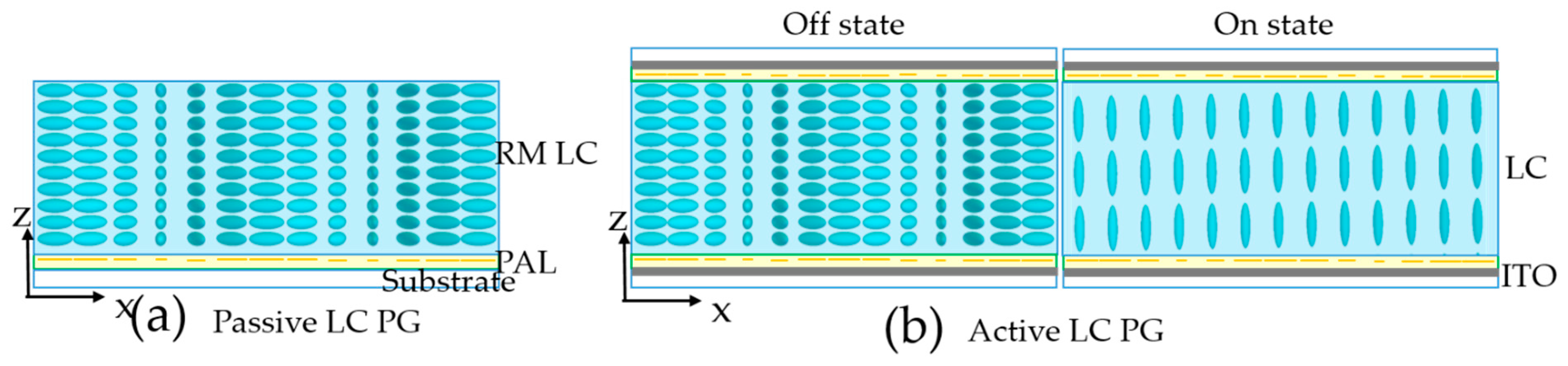
Based on the surface photoalignment technology, the most widely used PGs are fabricated into reactive mesogen polymer films [11] or electrically responsive LC cell [21], whose structures can be seen in Figure 3. To fabricate a polymeric (passive type) PG thin film, first a photoalignment layer is spin coated on the clean substrate and then exposed under a polarized field. Next, the prepared reactive mesogen mixture is coated on the surface and the UV light is applied for polymerization to form a stable thin film. The thickness of the film layer can be precisely controlled by the coating speed and the concentration of solution. To fabricate an electrically switchable (active type) LC PG, two prepared ITO substrates coated with photoalignment layer are assembled together to form an empty cell. By doing so, the cell gap can be determined by the dielectric spacers and the phase retardation can be tuned by the applied voltage and the electro-optical properties can be seen in [57]. Next, we photo align the cell with PG pattern and after that, we fill LC to the cell at a temperature above the clear point of the LC and then the LC cools to the room temperature. In addition, the transmissive case can be extended to the reflective mode by replacing the bottom glass substrate with a reflective substrate, as mentioned in [58,59].
3.1.2. Bulk Photoalignment
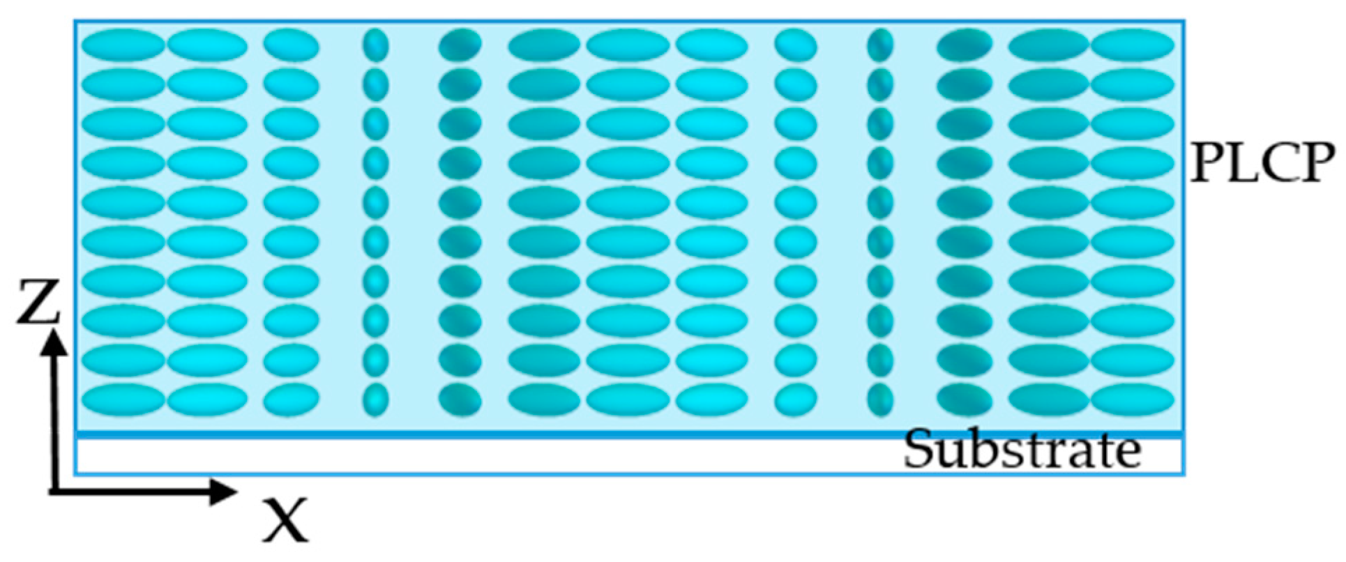
In contrast to surface photoalignment technology, bulk photoalignment can be also used as an alternative method to fabricate LC PG. This approach uses a photo-crosslinkable LC polymer material for the creation of LC PG. Photo-crosslinkable LC polymethacrylate consists of mesogenic biphenyl side groups and photoreactive cinnamic ester groups [60]. This polymer material is dissolved in solvent 1,1,1-trichloroethane and then spin coated on a substrate to form a homogeneous thin film. After that, the polymer film is exposed under a space-variant polarized light field at room temperature resulted in the photocycloaddition of cinnamate moieties. Next, film anneal is processed at the glass transition temperature above to enhance the birefringence and eventually cause the bulk alignment [61]. A transmissive-type LC PG based on bulk alignment can be seen in Figure 4. It uses all-in-one material that ensures an independence of the molecular orientation from any patterned surface of the alignment layer to simplify the fabrication procedure. This method creates symmetric and slanted LC PG with higher spatial resolution and higher efficiency [34].
3.2. Polarization Holography
3.2.1. Interference Methods
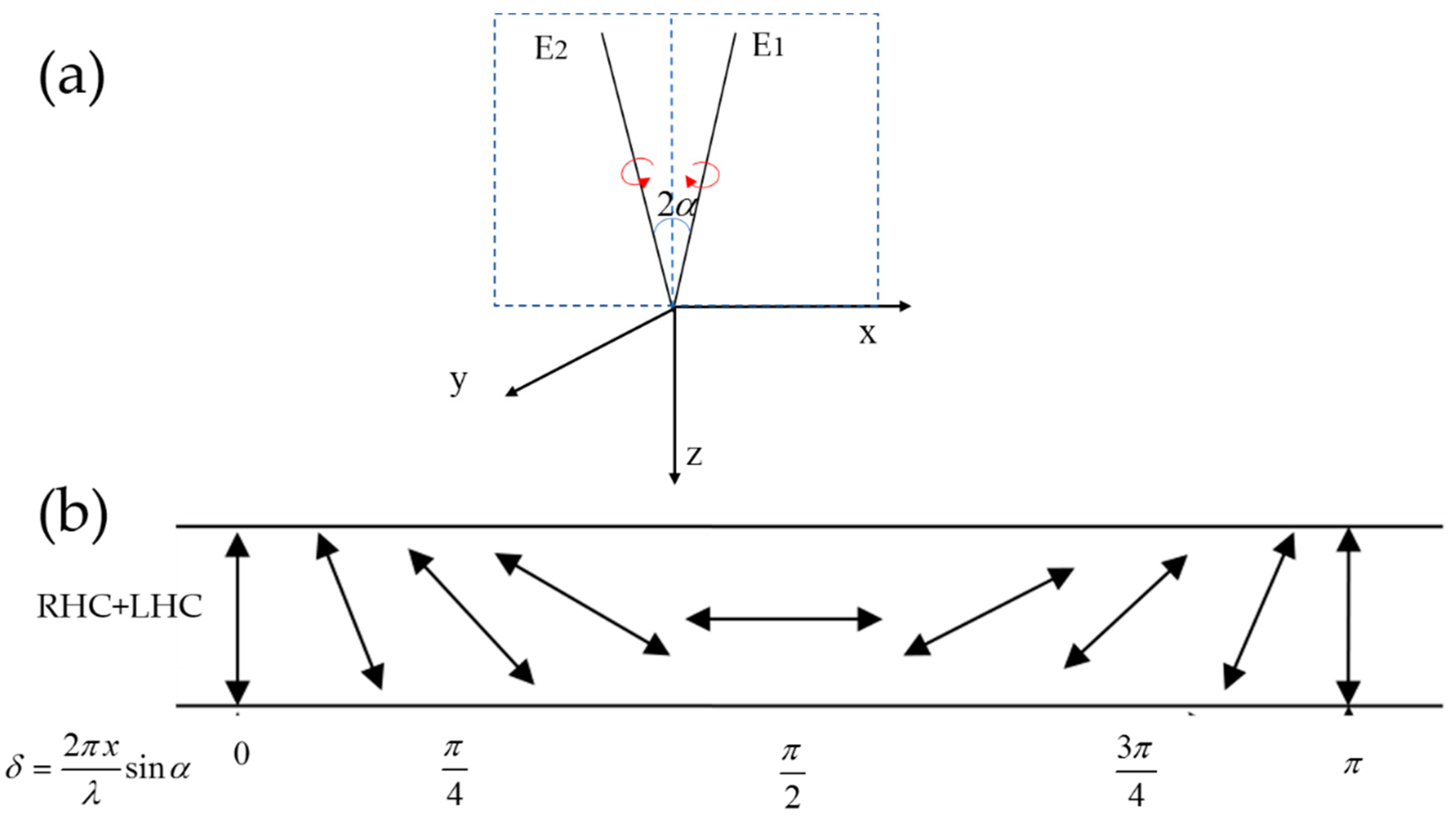
Polarization interference method can be used to generate the polarization holograms for LC alignment with high-resolution. As seen in Figure 5a, spatial-varying linear polarization are formed by the interference pattern of two plane waves and with equal intensity and orthogonal circular polarization. When and are left-handed circular polarization (LCP) and right-handed circular polarization (RCP), the electric vectors can be written as:
and
where and are the wave vectors of and , and is half of the angle between these two waves. The electric filed of the resulting interference pattern at x-y plane can be written as:
The z component can be neglected because is usually very small. The eventually electric field in Jones vector can be formulated as , where . The interference pattern can be seen in Figure 5b. The electric field intensity is constant and the linear polarization state rotates periodically along the x-axis in counter clockwise direction.
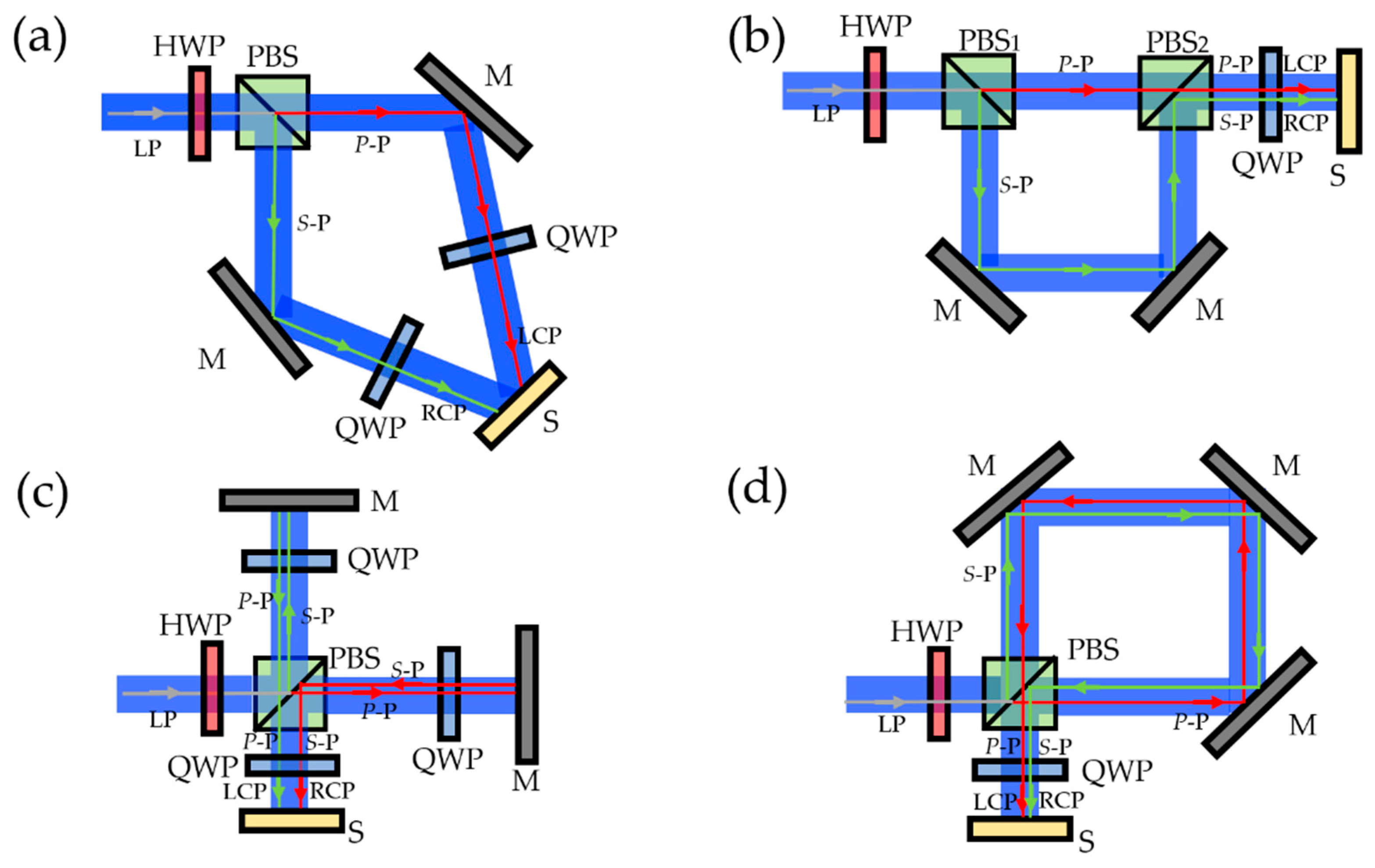
The periodical polarization holograms mentioned above can be recorded by polarization-sensitive materials and furtherly transferred to LC to form a one-dimensional PG. Several types of dual-beam interferometer based on the optical path differences can be utilized to generate the high-resolution polarization hologram. Figure 6a is the conventional polarization interferometer [32,62,63], which is established for exposing the PG with relatively short periods. Polarizing beam splitter (PBS) is utilized to split light into reflected s-polarized and transmitted p-polarized components. For splitting these two components with equal intensity, an HWP is inserted prior to the PBS to change the linear polarization direction. Subsequently, these two beams are deflected by mirrors and normally incident on the quarter wave plates (QWPs). Here, the slow axis of QWP in two arms is oriented at with respect to the input polarization direction, converting s-polarization and p-polarization into LCP and RCP, respectively. Finally, these two orthogonal circular polarization beams with a certain crossing angle are superimposed together to get the desired polarization hologram on the substrate. To expose the PG with relatively large period, the optical setup shown in Figure 6a is not feasible because of its long optical path in space. Figure 6b–d are the Mach–Zehnder [30], Michelson [64], and Sagnac interferometers [65], which can be established to expose the photoalignment layer on the substrates with large periods, correspondingly. These two coherent beams can illuminate the photoalignment layer on the substrates with a small crossing angle by slightly rotating the mirror or PBS to generate the spatial-varying linear polarization periodically. In the Mach–Zehnder interferometer, the PBS closed to the input laser is to split the laser into two arms while the other PBS near the substrates is to combine the two arms together. After combing the two arms together, only one QWP oriented at with respect to s-polarization or p-polarization is arranged to generate two orthogonal circular polarizations. Unlike the Mach–Zehnder interferometer, Michelson counterpart fold the two arms together so that only one PBS is utilized to split the input laser and recombine the two arms together. After splitting by PBS, the polarization of s-polarized beam in one arm is converted into p-polarization as it travels twice of a QWP oriented at with respect to s-polarization. Meanwhile, the polarization of p-polarized beam in the other arm is flipped into s-polarization. After combining by PBS, these two beams with orthogonal linear polarizations are transferred into orthogonal circular polarizations by QWP. However, in these dual-path configurations discussed above, a stable external environment must be guaranteed to obtain the desired pattern with high accuracy. To decrease the impact of environmental perturbation and vibration, a modified Sagnac interferometer with common path can be designed for exposure, as shown in Figure 6d. The two beams with orthogonal linear polarization are superimposed together and then QWPs manipulate them into orthogonal circular polarizations. Such setup has reduced sensitivity to vibration, which improves the stability due to the common path nature.
Furtherly, two-dimensional (2D) PGs has been demonstrated. In References [66,67,68], the authors assemble the patterned substrates of the LC cell with orthogonal grating vectors for the top and bottom substrates, respectively. Reo Amano use a self-organized micro-pixelated LC structure to design the 2D PGs [69]. To directly generate the 2D polarization patterns, the multi-beam interference exposure systems are introduced [70,71,72,73,74]. The polarization patterns and the corresponding diffraction results raised interest for their rich diversity. The corresponding light intensity distribution and polarization hologram can be analyzed by the same interference theory as dual-beam interference. Here, several requirements should be met to get the feasible 2D PG pattern. Firstly, the intensity of interference field has no non-zero value in any location, otherwise the photoalignment materials cannot be completely aligned. Secondly, because the abrupt change of the polarization orientation will cause the random alignment of the molecules in the discontinuous area, the polarization should have 2D chiral superstructure arrangement and vary continuously so that the induced 2D PG can obtain the high first-order efficiency and the polarization-selectivity diffraction property. In [71], the authors demonstrated a 2D PG pattern via four-beam polarization interferometry of circularly polarized light. Soon after this, a 2D polarization structure was designed through multi-beam interference by introducing a weak linear beam into the three circular polarized beams configuration [72].
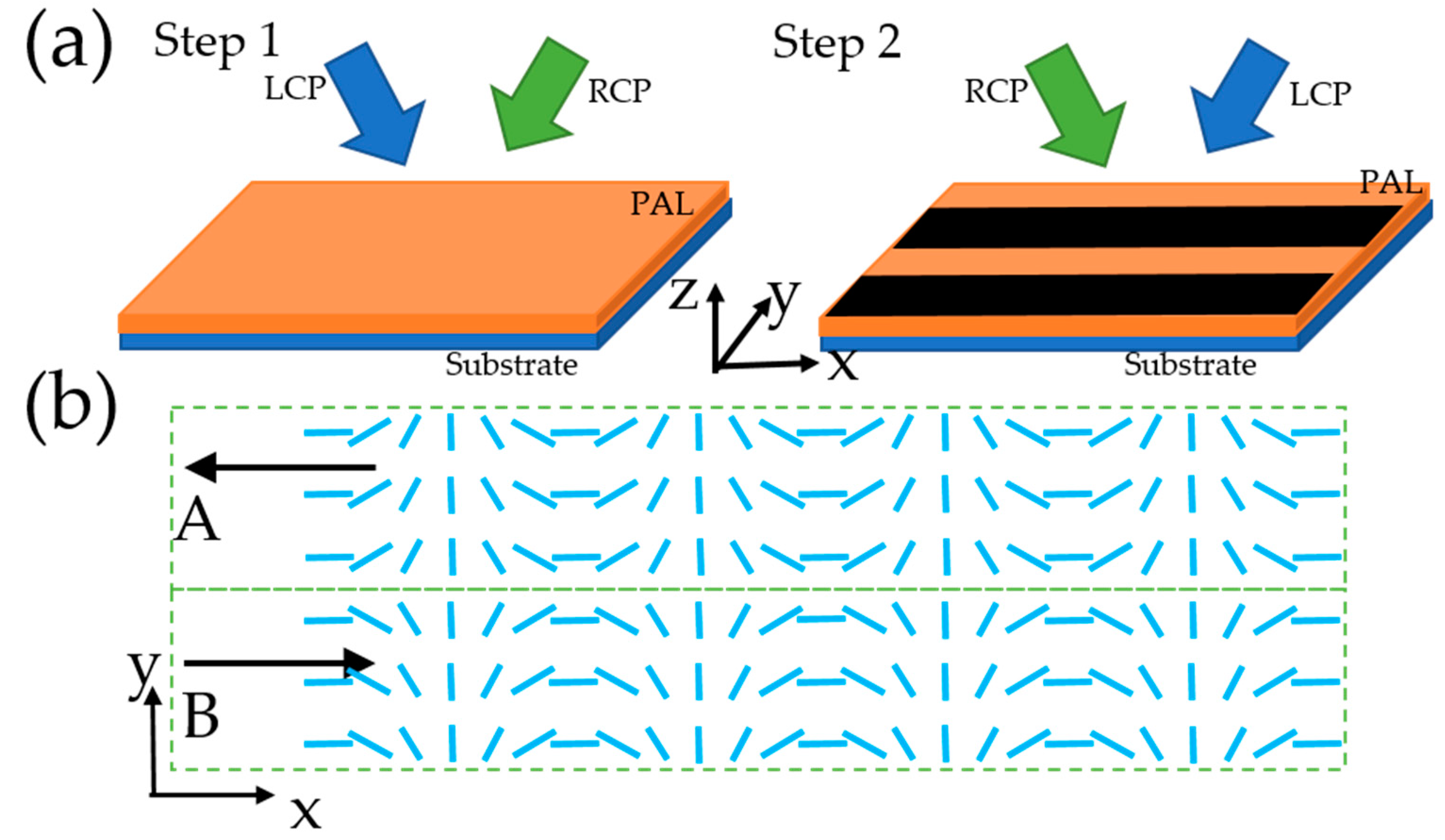
Multi-domain periodical LC structure can be applied in many display fields including holographic polarizers [75], CMOS polarization image sensor [76], and LC displays [77,78]. To photo-align the pixelated PG structure where each pixel governs a PG domain with independent grating vector, many methods were proposed such as multi-time rubbing, multi-step interference, building the nanostructure on the surface using the imprint method, or digital method as presented in Section 3.2.3. Among them, multi-step interference method is a relatively simple way to photo-align the multi-domain PG mother photomask with large area owing to the re-orientation property of photoalignment layer. Figure 7 depicts an example using the two-step interference to generate the two-domain PG alignment [79]. The whole area is exposed to the interference of two circularly polarized light with orthogonal handedness. After that, a second exposure step through the same interference method but with two orthogonal circularly polarized light in reversed handedness is processed under a mask with metallic strip to cover the whole substrate. The effective exposure zone of the second step generates the PG structure with reversed grating vector but the blocked area keeps the alignment direction of the primary exposure, as shown in Figure 7b.
3.2.2. Imprint Methods
The holographic interference method can be commonly used to generate the polarization hologram to expose the PB optical elements. If the mother mask already exists, the imprint method can be used to fabricate PG with the advantages of low cost, convenient process, and small occupied area [80].
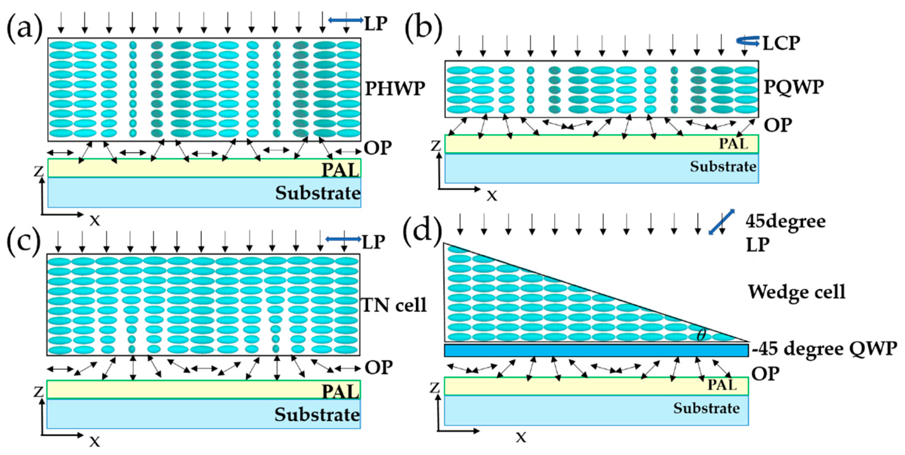
A mask PG with half wave thickness can be used as the photo mask and the basic operation proposal was first demonstrated by Rolic research Ltd. [81] and it has been even widely employed nowadays because of its characters of convenience and easy of fabrication [14]. The exposure system is illustrated in Figure 8a. The calculation for a x-directional linearly polarized light passing through a uniform HWP can be given by Jones Matrix as follows:
where is the angle between the slow axis and x-axis. As seen in Figure 8a, if is the spatial-varying angle to be formulated as where is the period of the mother PG photomask, the output polarization will be spatial-varying linear polarization and the direction angle is . Based on this imprint method, the PG can be generated from transferring the mother mask with a half-period . Thus, such easy configuration can be used to expose the short-period PG from a large-period one and even shorter one via multi-stack way [82,83]. Similarly, phase-integrated type LC devices such as fork grating, spatial-separation lens, and bifocal vortex generators can also be fabricated through this type of exposure configuration [15,23,84].
Besides the patterned HWP, the PG-patterned QWP can be employed as the mother mask to transfer the structure [15,85]. If the illuminated source is circular polarization, the calculation for a circularly polarized light passing through the uniform QWP can be given as:
Here, the output light is linear polarization with angle shift of and from the slow axis of the QWP, besides, a phase shift of and also occurs with regard to LCP and RCP. Therefore, as illustrated in Figure 8b, the spatial-changing linear polarization distribution with the same period can be generated to expose the photo alignment layer via transferring from a mother PG with quarter wave thickness.
The twisted nematic mode is one of the most commonly used modes in the LC displays [86]. Due to the polarization-guide effect, the twisted nematic cells can be also used as polarization converters. The obtained twisted nematic cell with a linear polarization conversion can be used as a mask to implement the photoalignment [16]. The experimental setup for LC PG photoalignment is shown in Figure 8c. The top alignment of the twisted nematic cell is uniform, while the alignment on the bottom substrate is designed to be the same alignment structure as PG. Therefore, when the input polarization is parallel to the top alignment, the output polarization will be spatially changed following the bottom alignment structure, which can be used to align a PG. The photoalignment method using twisted nematic cell has the advantages of simple configuration, convenient use, low cost and high efficiency. Moreover, the twisted nematic LC is achromatic for twist angle (Mauguin condition), which makes the approach broadband-available [16,87,88].
These LC PG photoalignment methods are based on transferring the grating structure on the mother mask to the new substrate. Nevertheless, the mother alignment structure is essential and the spatial resolution of LC PGs depends on the mother mask. Here, a non-interferometric method based on the phase retardation variation is used to form the polarization rotation for photoalignment [17]. The optical system for generating the continuous PG structure can be seen in Figure 8d. The input is linearly polarized light with 45 degrees to x-axis and therefore the polarization state can be formulated into . The light propagates along the z-axis. The wedge cell filling with LC function as the spatially varying retardation layer and the slow axis of the wedge cell is along the x-axis. The local phase retardation of the wedge cell can be formulated as , where is the birefringence of the LC materials and is the wavelength of the illuminated light.
Based on the Jones Matrix, the light after passing through the wedge cell can be calculated as:
The slow axis of the following QWP is at −45 degree with respect to x-axis. The output light after passing through the QWP for photoalignment can be calculated as:
From Equation (12), we find that the output light is linear polarization and the polarization direction angle is with respect to x-axis, meaning that the output linear polarization can be controlled by the phase retardation of the wedge cell and the output light is linearly changing, which is the same as the PG alignment structure. The principle of generating such a polarization conversion can be also understood in the following way. The x and y components of the input electric field have the equal amplitude in the uniaxial retardation and get a phase difference. After passing through the QWP, they become circular polarization with opposite handedness with a phase difference and the superposed light is linear polarization whose direction can be determined by . Based on the output polarization distribution, we can calculate out that the period of the PG alignment structure is: . Based on the same working principle, the cascaded configuration including a polarizer, a birefringent prism and a QWP with designed orientation can be also set for PG photoalignment [62,63,89], which can continuously modulate the polarization state of exposure beams. These methods can be implemented in a single-step exposure setup and with a single-beam system. Compared with the two-beam interference, these methods have the advantages of being more robust, having a lower cost, occupying a smaller space, and offering a simpler design.
3.2.3. Digital Methods
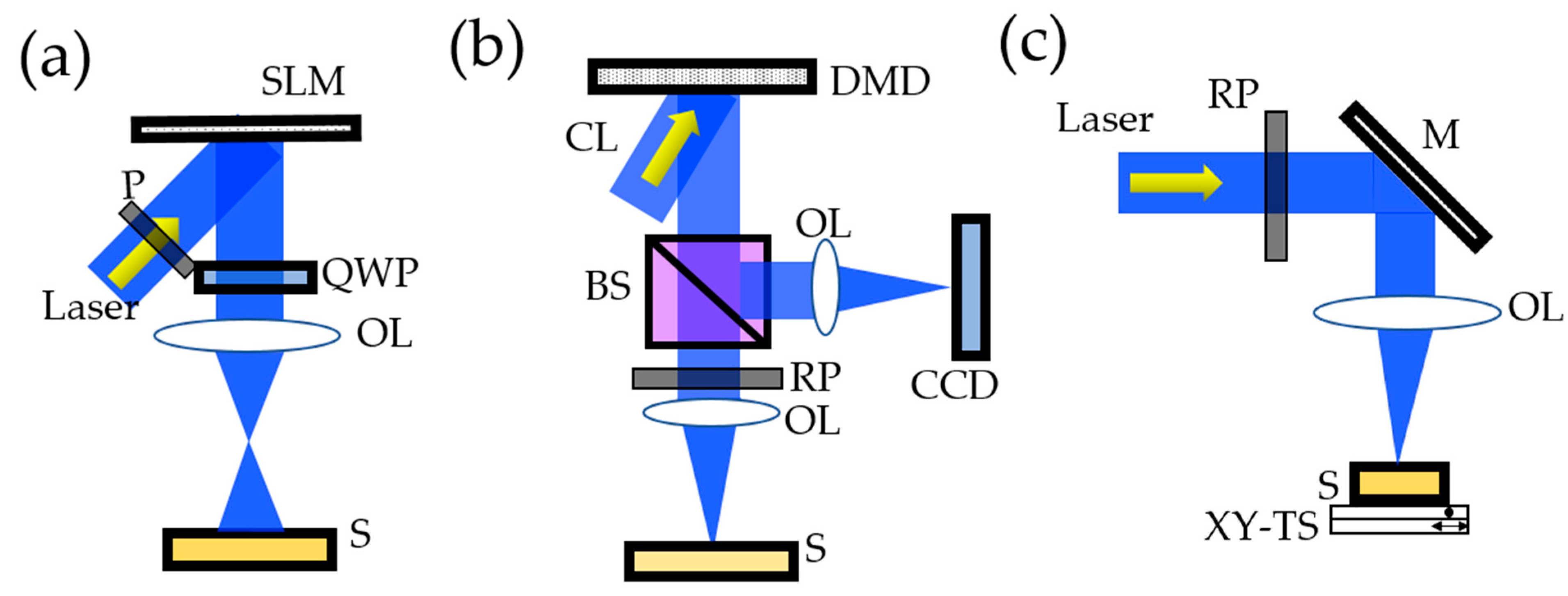
Besides interference and imprint methods, digital methods offer a larger freedom of design in the PG. As shown in Figure 9a, arbitrary polarization pattern such as PG structure can be digitally generated using a spatial light modulator (SLM) [18,90]. The principle is the same as the method using a wedge cell in Section 3.2.2. The phase retardation of light in each pixel can be precisely controlled by the pixel level of SLM. The polarization hologram is then generated after passing through the QWP. Secondly, because each pixel of digital micro-mirror device (DMD) can be switched between on and off state independently, DMD based lithography system can form the spatial-changing periodical polarization structure or even arbitrary polarization distribution through multistep process [19,91,92]. As shown in Figure 9b, the system consists of a light emission source, a dynamic pattern module, an image focusing module, and a monitor module. The collimated light projected to the on-state micro-mirrors is reflected to form a desired pattern. After passing through a motorized rotatable polarizer, linearly polarized light in a designed direction is obtained. Subsequently, it illuminates the substrates after focusing by an objective lens. Here, a charge-coupled device (CCD) is utilized to monitor the focusing process. The drawback of digital method is that patterns are quasi-continuous and a trade-off between the effective area and the spatial resolution exists. Figure 9c shows the direct-writing device for complex LC patterns [20,93]. The exposure position can be precisely controlled by a two-dimensional translation stage. A desired arbitrary polarization pattern from continuous scanning the focused spot can be directly written to the substrate.
4. Applications
4.1. Multi-Functional Photonic Devices
4.1.1. Orbital Angular Momentum Generator and Controller
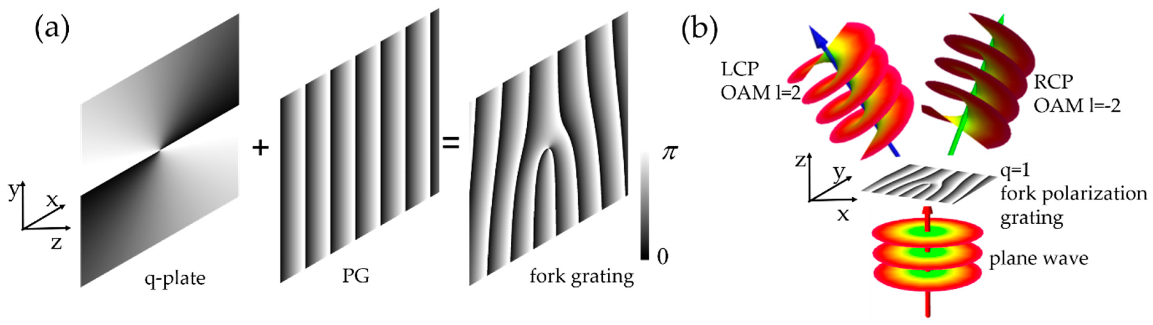
Vortex beam carrying orbital angular momentum (OAM) has attracted great attention due to their ability to carry information, detect shape, and manipulate particles [94,95,96,97,98]. OAM of photons can be expressed as a helical phase front: , where and are the topological charge and azimuthal angle, respectively [99]. Taking advantage of the strong optical spin to orbit interaction on the traditional LC q-plate, one can realize a direct transformation of the optical angular momentum and thereby convert the OAM state of light to a new mode with adding an additional topological charge of where the sign depends on the spin state [100,101,102,103,104]. In terms of the spin-split effect of PG, it can spatially separate OAMs with different modes into either or diffraction orders and their propagation directions are determined by spin states [15,105]. As seen in Figure 10a, a high-efficient OAM generator and controller based on fork polarization grating can be considered as an integration of traditional one-dimensional PG and q-plate, whose azimuthal angle of LC directors in the x-y plane can be formulated as , where is a constant. Figure 10b shows the schematic diagram and diffraction property of a liquid crystal fork polarization grating with under plane wave illumination. The and diffraction order is LCP with OAM charge and RCP with OAM charge , correspondingly. Similarly, PG can be also used to generate and manipulate other structured light such as Airy beam [106], vortex-focusing and defocusing light [107].
4.1.2. Spin Hall Meta-Lens
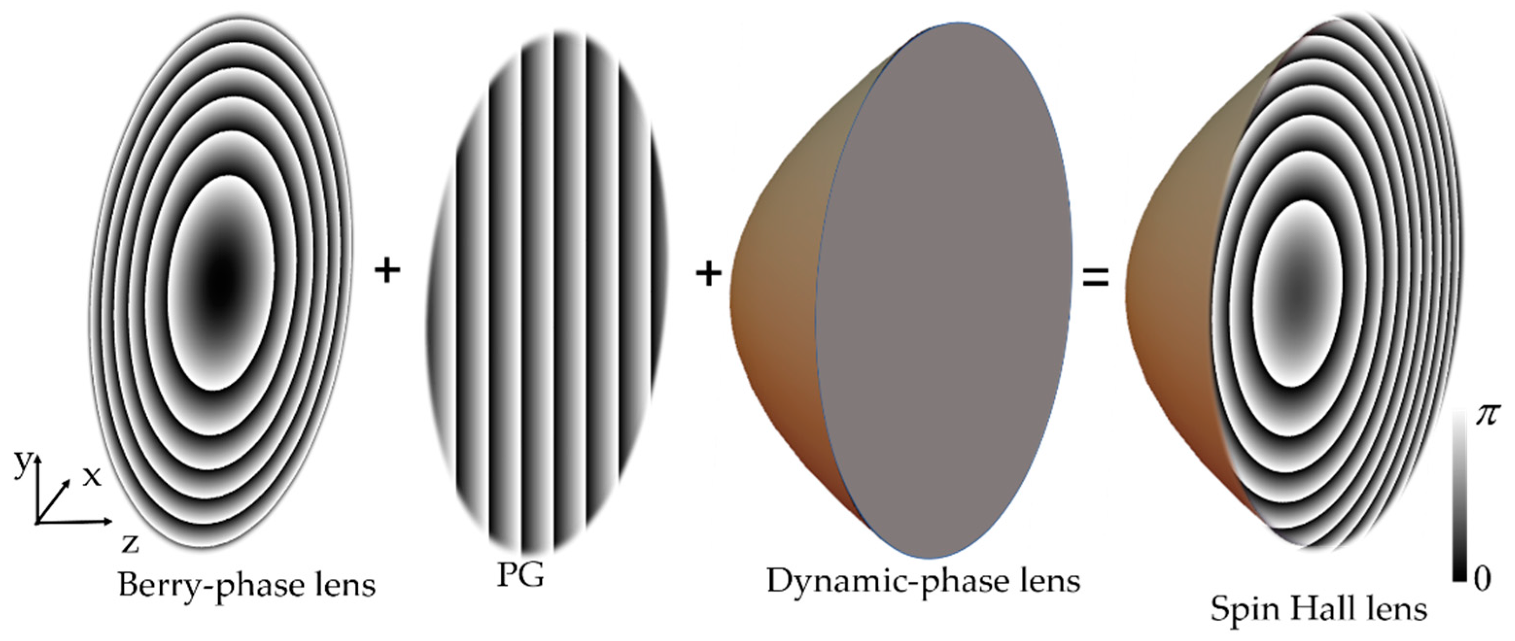
In order to realize the multidimensional spin-dependent splitting in both transverse and longitudinal direction in free space simultaneously by a single device, a photonics spin Hall meta-lens is designed and proposed by integrating PB lens and PG into a conventional dynamic phase lens, as seen in Figure 11 [23,108]. The local slow axis of the meta-lens can be written as where the first item represents the profiles of lens with focal length to focus one spin component and to defocus the other spin component, and the second item represents the linear profiles of PG with period , which generate the transverse spin-dependent splitting. After combining with the dynamic phase lens with focal length , the total phases can be written as , where the sign corresponds to LCP and RCP, respectively. It demonstrates that the meta-lens is a combination of an ultrathin convex/concave lens, beam splitter, and dynamic phase lens. Therefore, the focal length of the meta-lens can be calculated as: . Such integration approach for meta-lens provides one more degree of freedom and implements the functions with spin-dependent splitting, imaging, and spatially separated focusing. In comparison with intensity type bifocal lens HOE [109], spin Hall meta-lens based on PB phase integration can be considered as a special kind of holographic optical element (HOE). HOE is based on polarization holography, which is formed by recording the polarization states of an electric field based on photoinduced anisotropy [110]. The new PB phase optical element is designed by adding PB lens and grating, exhibiting a hybrid function. In addition, PB phase optical elements have the feature of polarization-selectivity and high efficiency. It can be used in polarization-multiplexed multi-plane off-axis imaging and displays [111]. The presented method circumvents the limitations of bulky optical devices in traditional integrated optics and it drastically increases the impact on multifunctional optical elements.
4.2. Information Processing and Displays
4.2.1. Beam Steering System
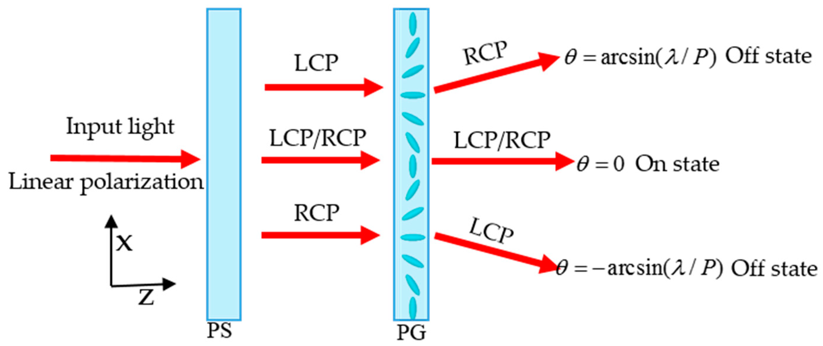
Changing and tracking the optical direction is highly required in free-space optical communications, laser weapons, remote sensing and fiber-optics [22]. Thanks to the grating diffraction, LC PGs can non-mechanically steer the beam to a certain angle based on the handedness of input light and the applied voltage [112,113,114,115]. As shown in Figure 12, a single beam steering stage consists of a polarization switch (PS) (e.g., a TN cell in combination with a QWP [116]) and a switchable PG. The polarization of input light changes from linear polarization to LCP or RCP after passing through a PS. Afterwards, LCP or RCP light deflects an angle and then diffracts to or order by the LC PG. If the LC PG is switched on by applying a voltage, the diffraction effect disappears and therefore light transmits to order. Here, it can be seen that this system enables beam steering in three different directions by individually switching the LC PG and modulating PS. To obtain multiple steering angles, the obvious method is to stack multiple stages consisting of PS and PG. In this system, the total number of steering angles are determined by the number of stages . If the LC PG in each stage has a different grating period, the total steering angles can be expressed as: . However, this non-mechanical beam steering system cannot steer light continuously. To realize the continuous and high-throughput beam steering, one typical approach is to use Risley gratings comprised of two independently rotating, inline PGs [117]. In conclusion, thanks to the single-order diffraction, polarization selectivity behavior and wide acceptance angle of PGs, optical systems based on PGs can accomplish the wide-angle beam steering in a high efficiency, compact, and light-weight way.
4.2.2. Edge Detection
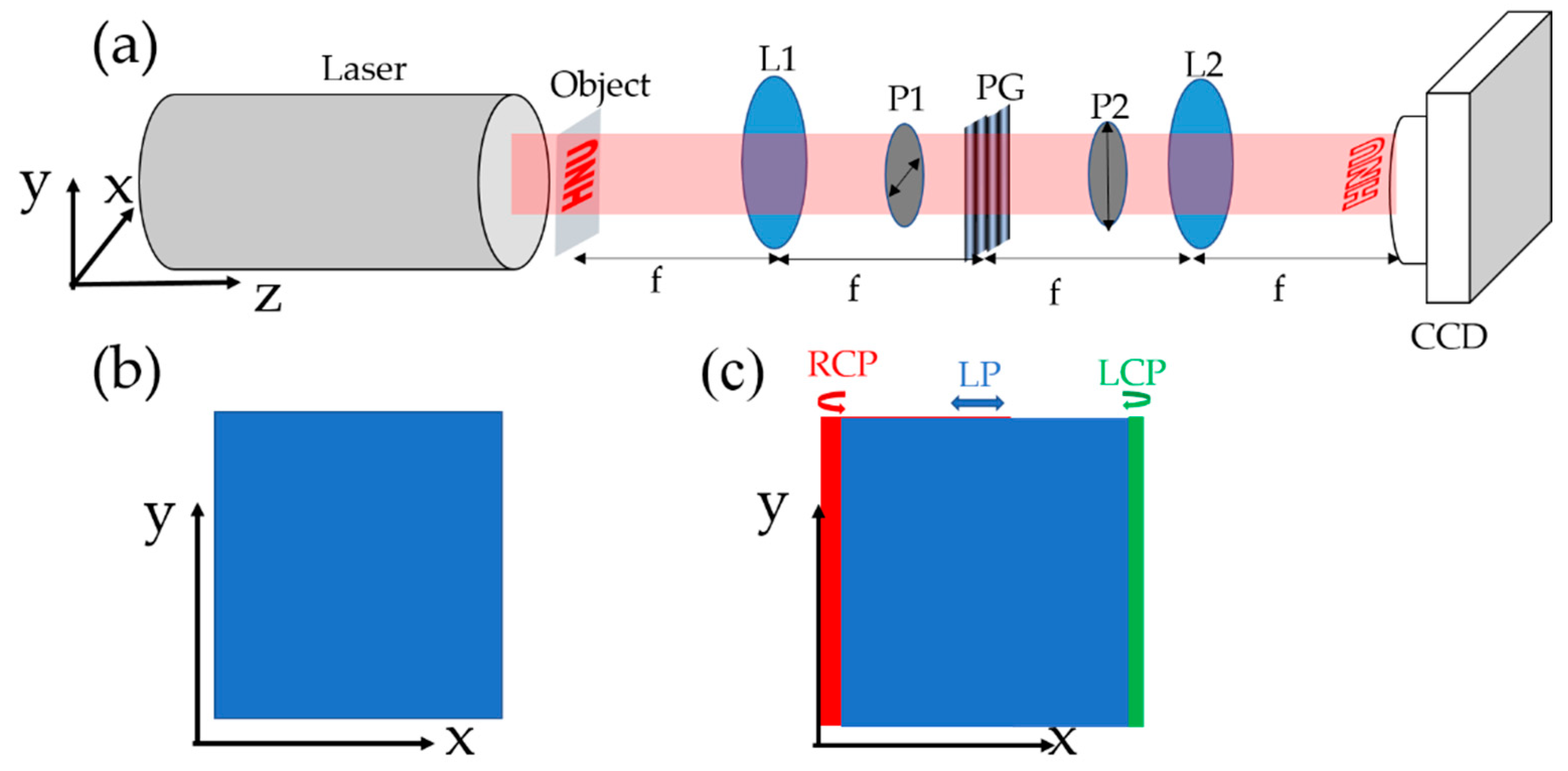
Edge detection can significantly improve the system efficiency and accuracy in image processing, computing and machine vision because it can obviously reduce the amount of stored data but reserve the key image information at the same time. Many approaches can realize the edge detection, mainly divided into digital [118] and analog [24,119,120,121,122,123,124] processing methods. Among them, an optical analog method based on the PG shows the advantages of ultra-fast processing speeds and low power consumption. The fundamental optical setup is proposed and demonstrated in Figure 13a. A 4f optical imaging system consisting of two lenses with identical focus length is installed. Here, the distance between the two lenses is 2f and the PG is inserted in the middle of them. The object is placed at one focal length in front of the first lens and the CCD is placed at one focal length after the second lens. Thus, the first lens conducts the Fourier transformation of the object at its back focal plane, which is also the location of the LC PG. Then, the second lens fulfills another Fourier transformation so that the corresponding diffraction pattern can be collected and observed in a CCD. In addition, a PG can implement the optical spatial differentiator while the two orthogonally directional polarizers filter out the edge information. To better understand the edge-detection concept of this work, consider a square-shaped object being introduced in our system, as shown in Figure 13b. It is illuminated by a linearly polarized light along x direction and the Jones vector of electric field can be formulated as . The PG will split the RCP and LCP components to different directions and the output electric field at image plane can be written as:
where , denotes the light wavelength, and is the focal length. From Equation (13), it can be found that the output light is composed of LCP and RCP with deviation distances . The final electric field in the image plane after passing through the whole system can be formulated as:
If the shift is much smaller than the image size, the amplitude of edge can be written as:
Here, because the period of the utilized PG is large, the shift is much smaller than the image size and is approximately proportional to the first-order spatial differentiation of the input light. As seen in Figure 13b, LCP and RCP images are projected at the image plane with a tiny shift. The overlapped region interferes LCP and RCP again and becomes original linear polarization. Thus, the second polarizer can eliminate the light in the overlapped region but the edge information in the non-overlapping part still exists.
In addition, the resolution of edge detection can be adjusted by applying different grating period [24]. More recently, changing the angles between the fringe directions of two PGs can realize the adjustable resolution at any real-time without varying the system construction, which provides a more feasible and effective method [122]. Furthermore, the edge detection can be extended to two dimensions based on a flat PB lens with large focus length [123] or a customized PB element comprising a symmetric phase gradient along the radical direction [124].
4.2.3. High Transmittance Holographic Polarizer
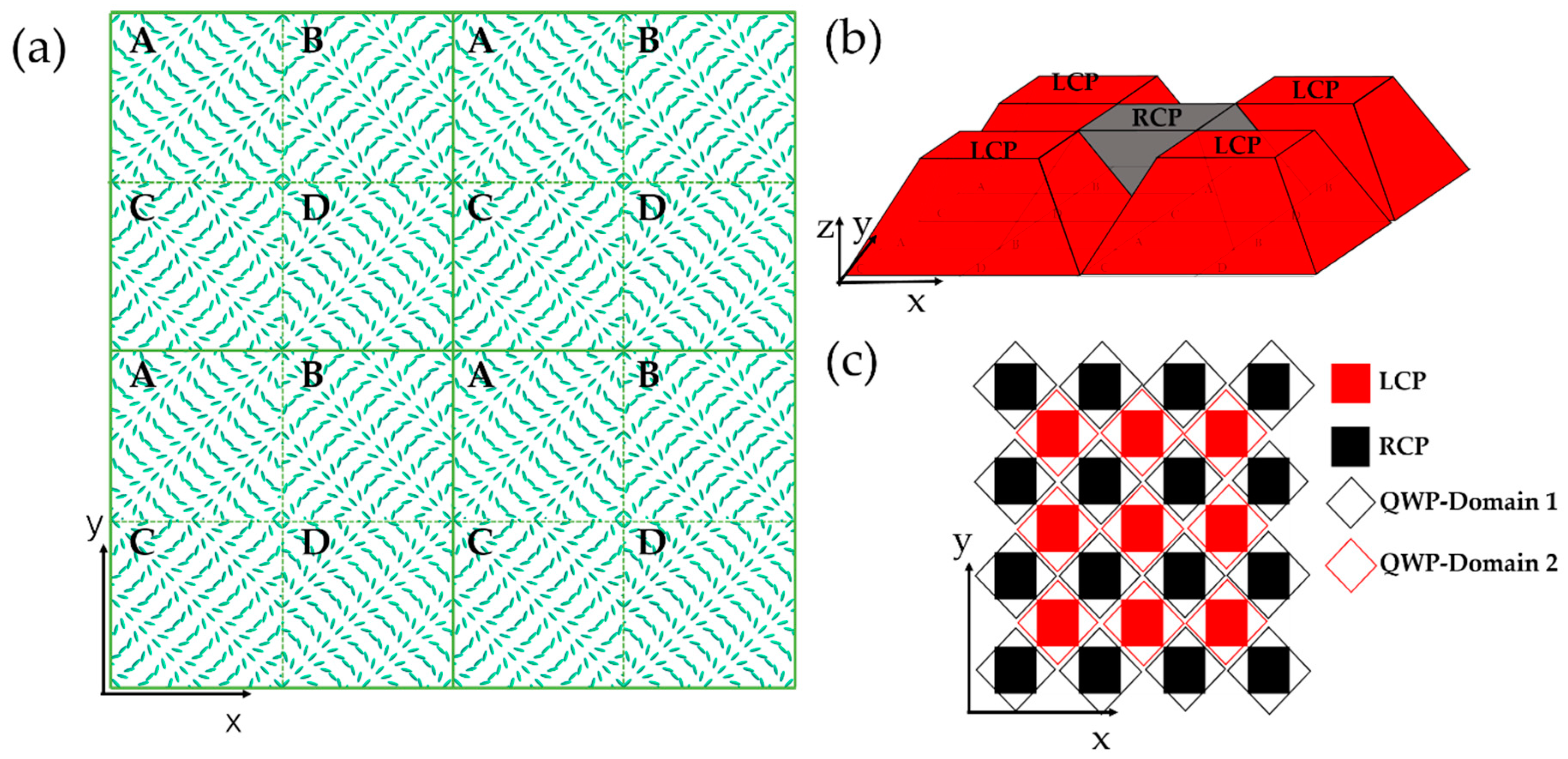
Polarizers play an important role in current display and photonic. Nowadays, the widespread polarizers are absorption-type and reflection-type caused that the transmittance ratio of unpolarized light is less than 50%. To improve the light efficiency, a high transmittance polarizer is developed based on the polarization conversion [39,75,125,126]. Here, a holographic polarizer consisted of structured PG and patterned QWP is shown with ideal 100% efficiency. As illustrated in Figure 14a, the basic optical function layer is a structured LC PG film periodically patterned with four domains: A, B, C, and D while, the grating vector in each domain points to the common center of the four domains. As we analyzed earlier, when the non-polarized input light transmits through the PG with half wave retardation, it will be spatially separated into LCP and RCP beams, which correspond to the +1st and −1st diffraction orders, respectively. As shown in Figure 14b, the propagation directions of light after passing through the PG film in each domain are determined by their local grating vectors. Benefited from the complex arrangement of LC patterns, LCP and RCP beams are spatially gathered and distinguished after a short distance away from the PG layer. This distance is determined by both the size of the microscale domain and the period of the LC structures. The broader distribution of LCP and RCP light at the plane of this distance can be seen in Figure 14c.
In order to develop the structured PG into a holographic polarizer, a patterned QWP with two domains is assembled in this given distance. The function of patterned QWP is to convert the circular polarization to linear polarization. Here, one domain covers all the LCP beams while the other domain covers all the RCP beams. It should be noted that the slow axis of domain 1 is perpendicular to that of domain 2, which is set for obtaining the homogeneous linear polarization output. Based on the analysis above, the holographic thin-film polarizer with high transmittance can be successfully designed via fitting the structured PG film and patterned QWP. Because the transmittance of conventional absorption and reflection type polarizer is less than 50%, such demonstrated holographic polarizer shows great potential to double the optical efficiency of polarizing optical systems like the backlights of LC displays. Moreover, the output light intensity with regard to holographic polarizer remains constant regardless of the direction angle of input polarization. That is to say, besides the property of high transmittance, the holographic polarizer can also present the unique character of polarization and intensity maintenance. The discovered character is of great significance for many photonics applications including photonic fibers and photonics waveguides, which can be further employed in optical communication systems.
4.2.4. Enlarging the Eyebox for Near-Eye Display
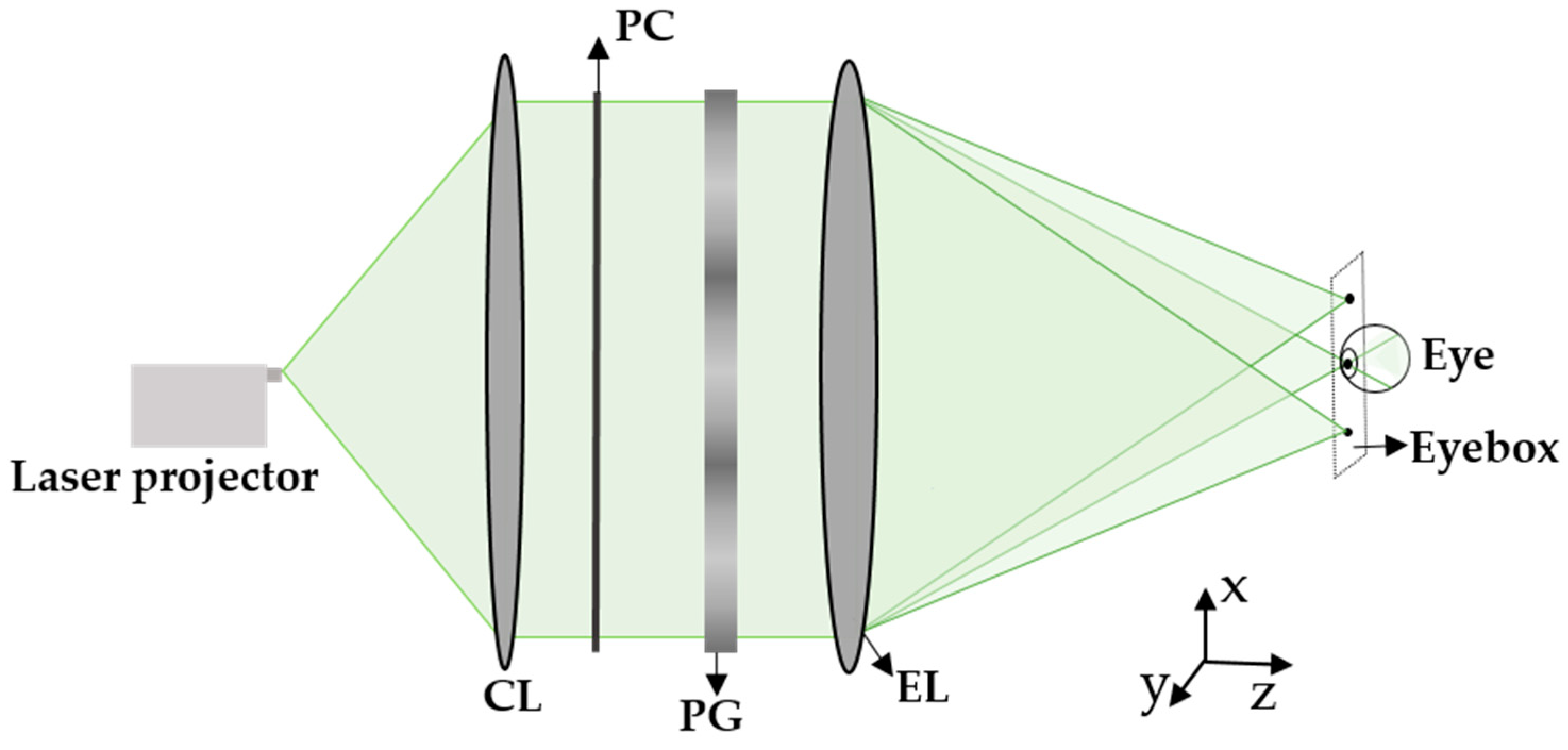
Currently, mismatch of converging and accommodation distance, called vergence-accommodation conflicts (VAC), remains in most of the current virtual reality (VR) and augment reality (AR) near-eye displays (NEDs) [127]. This major problem increases fusion time of binocular imagery and decreases fusion accuracy, which drawn the researchers to alleviate this issue. Several proposals were proposed to alleviate this issue including multi-focus display [128], light field display [129], holographic display [130], and Maxwellian display [25,131]. The working mechanism of alleviating VAC in Maxwellian-view displays is that the images can be directly projected to the retina by converging the light rays to the eye pupil. Therefore, it can present the always in-focus images regardless of the focus depth of human eye. Maxwellian-view NEDs have the obvious advantages including simpler optical system and higher optical throughput. Nevertheless, the eyebox size is relatively narrow, preventing its broader development. Here, in order to overcome the small eyebox limitation, a Maxwellian NED architecture with an expanded eyebox based on PG is demonstrated. As shown in Figure 15, a laser scanning projector is applied as the image source and a collimation lens to collimate light. The resulting polarized light rays after passing through the polarization controller (PC) are converged to the eye pupil of human by the eyepiece lens. When we insert a PG between the polarization controller and eyepiece lens, the efficiency of each order can be controlled by the input polarization and the phase retardation of PG. Thus, the collimation light is split into three orders with different diffraction angles and eventually be focused on different spot positions to enlarge the eyebox. In addition, the distance of adjacent focus spot is , where is the diffraction angle and x is the distance between the PG and the focus plane of eyepiece lens. In order to avoid the double image effect in the real scene, this space is usually designed to be a little larger than the eye pupil width. Further, the full-color display can be realized based on a double LC layer with twisted structures [25,29] and the eyebox size can be extended in two-dimensions through a customized Dammann grating [131,132]. In conclusion, our approach provides a simple way to enlarge the eyebox for Maxwellian-view NEDs while adding the negligible weight and volume.
5. Conclusions
In conclusion, we have reviewed some advances in the physical principles, fabrication methods of LC PGs. The relevant novel applications for photonics and displays are also introduced. Based on the photoalignment technology, the existing exposure methods including interference, patterned wave plate imprint, and digital approaches are crucial for LC alignment with high stability and good performance. Based on LC PG, many applications were demonstrated and developed. Firstly, the PG can be integrated to other PB phase elements or dynamic phase elements to generate and manipulate the structured light in micro-nano photonics area. It can be also applied to the meta-lens to accomplish spin-dependent splitting, spatially separated multi-focusing, and imaging, simultaneously. These findings provide extra degrees of freedom to manage polarization photonics and show more possibilities for exploiting multi-functional devices. Moreover, it can be used as a beam steering device or designed as a high-efficient holographic polarizer. It can also implement the edge detection to reduce the information amount and enlarge the eyebox in the near-eye displays.
In the future, more theoretical and experimental improvement in terms of LC PGs should be concerned. On the one hand, theoretical analysis of LC PGs with large diffraction angle, customized spectral and angular response are highly desirable for satisfying requirements of practical optical system. One the other hand, experimental demonstrations of LC PG based on photoalignment technology should be focused. Various generation methods of polarization hologram should be explored for exposing large area and high-resolution LC PG in a high-stable and low-cost way. In addition, benefiting from the optical properties of LC PG, a polarization-dependent off-axis imaging in a free space near-eye displays can be implemented by introducing a compact combiner with PG and lens phase profiles [111,133]. Additionally, eye-tracking [116], multifocal display [134], or extending the field of view [135,136] in the waveguide displays can be performed using LC PG as a prominent beam coupler. Hence, an increasing attention should be paid on applying LC PGs into more optical systems to address some difficulties. The widespread applications of LC PGs especially in imaging and wearable displays are foreseeable.
Author Contributions
T.L., J.X. and Y.Z. (Yingjie Zhou) wrote the manuscript. T.L., J.X., Y.Z. (Yaqin Zhou) and Y.Y. revised the manuscript. F.F. and S.W. supervised the manuscript. All authors have read and agreed to the published version of the manuscript.
Funding
National Natural Science Foundation of China (Grant No. 61605046 and 11574079), Natural Science Foundation of Hunan Province (Grant No. 2018JJ3069) and Hunan Provincial Innovation Foundation for Postgraduate (CX20190318).
Conflicts of Interest
The authors declare no conflict of interest.
References
- Cincotti, G. Polarization gratings: Design and applications. IEEE J. Quantum Electron. 2003, 39, 1645–1652. [Google Scholar] [CrossRef]
- Crawford, G.P.; Eakin, J.N.; Radcliffe, M.D.; Callan-Jones, A.; Pelcovits, R.A. Liquid-crystal diffraction gratings using polarization holography alignment techniques. J. Appl. Phys. 2005, 98, 123102. [Google Scholar] [CrossRef] [Green Version]
- Hooper, I.R.; Sambles, J.R. Dispersion of surface plasmon polaritons on short-pitch metal gratings. Phys. Rev. B 2002, 65, 165432. [Google Scholar] [CrossRef] [Green Version]
- Gorodetski, Y.; Biener, G.; Niv, A.; Kleiner, V.; Hasman, E. Space-variant polarization manipulation for far-field polarimetry by use of subwavelength dielectric gratings. Opt. Lett. 2005, 30, 2245–2247. [Google Scholar] [CrossRef]
- Bomzon, Z.; Biener, G.; Kleiner, V.; Hasman, E. Space-variant Pancharatnam-Berry phase optical elements with computer-generated subwavelength gratings. Opt. Lett. 2002, 27, 1141–1143. [Google Scholar] [CrossRef]
- Gori, F. Measuring Stokes parameters by means of a polarization grating. Opt. Lett. 1999, 24, 584–586. [Google Scholar] [CrossRef] [PubMed]
- Oh, C. Broadband Polarization Gratings for Efficient Liquid Crystal Display, Beam Steering, Spectropolarimetry, and Fresnel Zone Plate. Ph.D. Thesis, North Carolina State University, Raleigh, NC, USA, 2009. [Google Scholar]
- Honma, M.; Nose, T. Twisted nematic liquid crystal polarization grating with the handedness conservation of a circularly polarized state. Opt. Express 2012, 20, 18449–18458. [Google Scholar] [CrossRef] [PubMed]
- Kawai, K.; Sasaki, T.; Noda, K.; Sakamoto, M.; Kawatsuki, N.; Ono, H. Holographic binary grating liquid crystal cells fabricated by one-step exposure of photocrosslinkable polymer liquid crystalline alignment substrates to a polarization interference ultraviolet beam. Appl. Opt. 2015, 54, 6010–6018. [Google Scholar] [CrossRef] [PubMed]
- Serak, S.V.; Roberts, D.E.; Hwang, J.Y.; Nersisyan, S.R.; Tabiryan, N.V.; Bunning, T.J.; Steeves, D.M.; Kimball, B.R. Diffractive waveplate arrays. J. Opt. Soc. Am. B 2017, 34, B56–B63. [Google Scholar] [CrossRef]
- Escuti, M.J.; Oh, C.; Sanchez, C.; Bastiaansen, C.; Broer, D.J. Simplified spectropolarimetry using reactive mosogen polarization gratings. In Proceedings of the Imaging Spectrometry XI, SPIE Optics + Photonics, San Diego, CA, USA, 13–17 August 2006; Shen, S.S., Lewis, P.E., Eds.; SPIE Press: Bellingham, WA, USA, 2006; Volume 6302, p. 630207. [Google Scholar]
- Nikolova, L.; Todorov, T. Diffraction efficiency and selectivity of polarization holographic recording. Opt. Acta 1984, 31, 579–588. [Google Scholar] [CrossRef]
- Zhan, T.; Lee, Y.H.; Tan, G.; Xiong, J.; Yin, K.; Gou, F.; Zou, J.; Zhang, N.; Zhao, D.; Yang, J.; et al. Pancharatnam-Berry optical elements for head-up and near-eye displays. J. Opt. Soc. Am. B 2019, 36, D52–D65. [Google Scholar] [CrossRef]
- Nersisyan, S.R.; Tabiryan, N.V.; Steeves, D.M.; Kimball, B.R. Characterization of optically imprinted polarization gratings. Appl. Opt. 2009, 48, 4062–4067. [Google Scholar] [CrossRef]
- Fu, W.; Zhou, Y.; Yuan, Y.; Lin, T.; Zhou, Y.; Huang, H.; Fan, F.; Wen, S. Generalization of Pancharatnam-Berry phase interference theory for fabricating phase-integrated liquid crystal optical elements. Liq. Cryst. 2020, 47, 369–376. [Google Scholar] [CrossRef]
- Chen, P.; Ji, W.; Wei, B.Y.; Hu, W.; Chigrinov, V.; Lu, Y.Q. Generation of arbitrary vector beams with liquid crystal polarization converters and vector-photoaligned q-plates. Appl. Phys. Lett. 2015, 107, 241102. [Google Scholar] [CrossRef]
- Lee, D.; Kwak, K.; Jhun, C.G.; Choi, H.S.; Song, J.K. Maskless fabrication of film-patterned-retarder (FPR) using wedged liquid crystal cell. IEEE Photonics J. 2019, 11, 7001508. [Google Scholar] [CrossRef]
- Li, Y.; Liu, Y.; Li, S.; Zhou, P.; Zhan, T.; Chen, Q.; Su, Y.; Wu, S.T. Single-exposure fabrication of tunable Pancharatnam-Berry devices using a dye-doped liquid crystal. Opt. Express 2019, 27, 9054–9060. [Google Scholar] [CrossRef] [Green Version]
- Fu, W.; Zhou, Y.; Yuan, Y.; Lin, T.; Zhou, Y.; Huang, H.; Fan, F.; Wen, S. Symmetric Airy vortex and symmetric Airy vector beams. Liq. Cryst. 2020, 47, 369–376. [Google Scholar] [CrossRef]
- Kim, J.; Li, Y.; Miskiewicz, M.N.; Oh, C.; Kudenov, M.W.; Escuti, M.J. Fabrication of ideal geometric-phase holograms with arbitrary wavefronts. Optica 2015, 2, 958–964. [Google Scholar] [CrossRef]
- Wen, B.; Petschek, R.G.; Rosenblatt, C. Nematic liquid-crystal polarization gratings by modification of surface alignment. Appl. Opt. 2002, 41, 1246–1250. [Google Scholar] [CrossRef]
- He, Z.; Gou, F.; Chen, R.; Yin, K.; Zhan, T.; Wu, S.T. Liquid Crystal Beam Steering Devices: Principles, Recent Advances, and Future Developments. Crystals 2019, 9, 292. [Google Scholar] [CrossRef] [Green Version]
- Zhou, Y.; Yin, Y.; Yuan, Y.; Lin, T.; Huang, H.; Yao, L.; Wang, X.; Tam, A.M.W.; Fan, F.; Wen, S. Liquid crystal pancharatnam-Berry phase lens with spatially separated focuses. Liq. Cryst. 2019, 46, 995–1000. [Google Scholar] [CrossRef]
- Zhou, J.; Qian, H.; Chen, C.F.; Zhao, J.; Li, G.; Wu, Q.; Luo, H.; Wen, S.; Liu, Z. Optical edge detection based on high-efficiency dielectric metasurface. Proc. Natl. Acad. Sci. USA 2019, 116, 11137. [Google Scholar] [CrossRef] [Green Version]
- Lin, T.; Zhan, T.; Zou, J.; Fan, F.; Wu, S.T. Maxwellian near-eye display with an expanded eyebox. Opt. Express 2020, 28, 38616–38625. [Google Scholar] [CrossRef]
- Pancharatnam, S. Generalized theory of interference, and its applications. Proc. Indian Acad. Sci. A 1956, 44, 247–262. [Google Scholar] [CrossRef]
- Berry, M.V. Quantal phase factors accompanying adiabatic changes. Proc. R. Soc. A 1984, 392, 45–57. [Google Scholar]
- Goldstein, D. Polarized Light, 2nd ed.; Marcel Dekker: New York, NY, USA, 2003; pp. 226–227. [Google Scholar]
- Oh, C.; Escuti, M.J. Achromatic diffraction from polarization gratings with high efficiency. Opt. Lett. 2008, 33, 2287–2289. [Google Scholar] [CrossRef]
- Zou, J.; Zhan, T.; Xiong, J.; Wu, S.T. Broadband wide-view Pancharatnam-Berry phase deflector. Opt. Express 2020, 28, 4921–4927. [Google Scholar] [CrossRef]
- Moharam, M.G.; Young, L. Criterion for Bragg and Raman-Nath diffraction regimes. Appl. Opt. 1978, 17, 1757–1759. [Google Scholar] [CrossRef]
- Gao, K.; McGinty, C.; Payson, H.; Berry, S.; Vornehm, J.; Finnemeyer, V.; Roberts, B.; Bos, P. High-efficiency large-angle Pancharatnam phase deflector based on dual-twist design. Opt. Express 2017, 25, 6283–6293. [Google Scholar] [CrossRef]
- Xiang, X.; Kim, J.; Escuti, M.J. Bragg polarization gratings for wide angular bandwidth and high efficiency at steep deflection angles. Sci. Rep. 2018, 8, 7202. [Google Scholar] [CrossRef] [Green Version]
- Sakhn, O.; Gritsai, Y.; Sahm, H.; Stumpe, J. Fabrication and performance of efficient thin circular polarization gratings with Bragg properties using bulk photo-alignment of a liquid crystalline polymer. Appl. Phys. B 2018, 124, 52. [Google Scholar] [CrossRef]
- Xiong, J.; Wu, S.T. Rigorous coupled-wave analysis of liquid crystal polarization gratings. Opt. Express 2020, 28, 35960–35971. [Google Scholar] [CrossRef]
- Xiang, X.; Kim, J.; Komanduri, R.; Escuti, M.J. Nanoscale liquid crystal polymer Bragg polarization gratings. Opt. Express 2017, 25, 19298–19308. [Google Scholar] [CrossRef] [Green Version]
- Weng, Y.; Xu, D.; Zhang, Y.; Li, X.; Wu, S.T. Polarization volume grating with high efficiency and large diffraction angle. Opt. Express 2016, 24, 17746–17759. [Google Scholar] [CrossRef]
- Lee, Y.H.; Yin, K.; Wu, S.T. Reflective polarization volume gratings for high efficiency waveguide-coupling augmented reality displays. Opt. Express 2017, 25, 27008–27014. [Google Scholar] [CrossRef]
- Yin, K.; Zhan, T.; Xiong, J.; He, Z.; Wu, S.T. Polarization volume gratings for near-eye displays and novel photonic devices. Crystals 2020, 10, 561. [Google Scholar] [CrossRef]
- Zhang, S.; Chen, W.; Yu, Y.; Wang, Q.; Mu, Q.; Li, S.; Chen, J. Twisting structures in liquid crystal polarization gratings and lenses. Crystals 2021, 11, 243. [Google Scholar] [CrossRef]
- Kgelnik, H. Imaging of optical modes—Resonators with internal lenses. Bell Syst. Tech. J. 1969, 48, 2909–2947. [Google Scholar] [CrossRef]
- Magnusson, R.; Graylord, T.K. Analysis of multiwave diffraction of thick gratings. J. Opt. Soc. Am. 1977, 67, 1165–1170. [Google Scholar] [CrossRef]
- Xiang, X.; Escuti, M.J. Numerical analysis of Bragg regime polarization gratings by rigorous coupled-wave analysis. In Proceedings of the Practical Holography XXXI: Materials and Applications, SPIE OPTO, San Francisco, CA, USA, 28 January–2 February 2017; Bjelkhagen, H.I., Bove, V.M., Eds.; SPIE Press: Bellingham, WA, USA, 2017; 10127, p. 101270D. [Google Scholar]
- Xiang, X.; Escuti, M.J. Numerical analysis of Bragg polarization gratings. J. Opt. Soc. Am. B 2019, 36, D1–D8. [Google Scholar] [CrossRef]
- Xiang, X.; Escuti, M.J. Numerical modeling of polarization gratings by rigorous coupled wave analysis. In Proceedings of the Emerging Liquid Crystal Technologies XI, SPIE OPTO, San Francisco, CA, USA, 13–18 February 2016; Chien, L.-C., Broer, D.J., Kikuchi, H., Tabiryan, N.V., Eds.; SPIE Press: Bellingham, WA, USA, 2016; Volume 9769, p. 976918. [Google Scholar]
- Ishiguro, M.; Sato, D.; Shishido, A.; Ikeda, T. Bragg-type polarization gratings fromed in thick polymer films containing azobezene and tolane moieties. Langmuir 2007, 23, 332–338. [Google Scholar] [CrossRef] [PubMed]
- Honma, M.; Nose, T. Polarization-independent liquid crystal grating fabricated by microrubbing process. Jpn. J. Appl. Phys. 2003, 42, 6992–6997. [Google Scholar] [CrossRef]
- Kim, J.H.; Yoneya, M.; Yokoyama, H. Tristable nematic liquid-crystal device using micropatterned surface alignment. Nature 2002, 420, 159–162. [Google Scholar] [CrossRef]
- Lee, C.H.; Yoshida, H.; Miura, Y.; Fujii, A.; Ozaki, M. Local liquid crystal alignment on patterned micrograting structures photofabricated by two photon excitation direct laser writing. Appl. Phys. Lett. 2008, 93, 173509. [Google Scholar] [CrossRef]
- He, Z.; Tan, G.; Chanda, D.; Wu, S.T. Novel liquid crystal photonic devices enabled by two-photon polymerization. Opt. Express 2019, 27, 11472–11491. [Google Scholar] [CrossRef]
- Chigrinov, V.G.; Kozenkov, V.M.; Kwok, H.S. Photoalignment of Liquid Crystalline Materials: Physics and Applications; John Wiley & Sons Ltd.: Chichester, UK, 2008. [Google Scholar]
- Ichimura, K. Photoalignment of liquid-crystal systems. Chem. Rev. 2000, 100, 1847–1874. [Google Scholar] [CrossRef] [PubMed]
- Culbreath, C.; Glazar, N.; Yokoyama, H. Note: Automated maskless micro-multidomain photoalignment. Rev. Sci. Instrum. 2011, 82, 126107. [Google Scholar] [CrossRef] [Green Version]
- Guo, Y.; Jiang, M.; Peng, C.; Sun, K.; Yaroshchuk, O.; Lavrentovich, O.; Wei, Q.H. High-resolution and high-throughput plasmonic photopatterning of complex molecular orientations in liquid crystals. Adv. Mater. 2016, 28, 2353–2358. [Google Scholar] [CrossRef]
- Ichimura, K.; Suzuki, Y.; Seki, T.; Hosoki, A.; Aoki, K. Reversible change in alignment mode of nematic liquid crystals regulated photochemically by command surfaces modified with an azobenzene monolayer. Langmuir 1988, 4, 1214–1216. [Google Scholar] [CrossRef]
- Shteyner, E.A.; Srivastava, A.K.; Chigrinov, V.G.; Kwok, H.-S.; Afanasyev, A.D. Submicron-scale liquid crystal photo-alignment. Soft Matter 2013, 9, 5160–5165. [Google Scholar] [CrossRef]
- Chen, J.; Bos, P.J.; Vithana, H.; Johnson, D.L. An electrooptically controlled liquid-crystal diffraction grating. Appl. Phys. Lett. 1995, 67, 2588–2590. [Google Scholar] [CrossRef]
- Komanduri, R.K.; Escuti, M.J. High efficiency reflective liquid crystal polarization gratings. Appl. Phys. Lett. 2009, 95, 091106. [Google Scholar] [CrossRef] [Green Version]
- Komanduri, R.K.; Oh, C.; Escuti, M.J. Reflective liquid crystal polarization gratings with high efficiency and small pitch. In Proceedings of the Liquid Crystals XII, Photonic Devices + Applications, San Francisco, CA, USA, 10–14 August 2008; Khoo, I.C., Ed.; SPIE Press: Bellingham, WA, USA, 2008; Volume 7050, p. 70500J. [Google Scholar]
- Emoto, A.; Matsumoto, T.; Yamashita, A.; Shioda, T.; Ono, H.; Kawatsuki, N. Large birefringence and polarization holographic gratings formed in photocross-linkable polymer liquid crystals comprising bistolane mesogenic side groups. J. Appl. Phys. 2009, 106, 073505. [Google Scholar] [CrossRef]
- Ono, H.; Emoto, A.; Takahashi, F.; Kawatsuki, N.; Hasegawa, T. High stable polarization gratings in photocrosslinkable polymer liquid crystals. J. Appl. Phys. 2003, 94, 1298–1303. [Google Scholar] [CrossRef]
- Kim, J.; Komanduri, R.K.; Escuti, M.J. A compact holographic recording setup for tuning pitch using polarizing prisms. In Proceedings of the Practical Holography XXVI: Materials and Applications, SPIE OPTO, San Francisco, CA, USA, 21–26 January 2012; Bjelkhagen, H.I., Bove, V.M., Eds.; SPIE Press: Bellingham, WA, USA, 2012; Volume 8281, p. 82810R. [Google Scholar]
- Miskiewicz, M.N.; Kim, J.; Li, Y.; Komanduri, R.K.; Escuti, M.J. Progress on large-area polarization grating fabrication. In Proceedings of the Acquisition, Tracking, Pointing, and Laser Systems Technologies XXVI, SPIE Defense, Security, and Sensing, Baltimore, MD, USA, 23–27 April 2012; Thompson, W.E., McManamon, P.F., Eds.; SPIE Press: Bellingham, WA, USA, 2012; Volume 8395, p. 83950G. [Google Scholar]
- Huang, Y.H.; Li, M.S.; Ko, S.W.; Fuh, A.Y.G. Helical wavefront and beam shape modulated by advanced liquid crystal q-plate fabricated via photoalignment and analyzed by Michelson’s interference. App. Opt. 2013, 52, 6557–6561. [Google Scholar] [CrossRef] [PubMed]
- Zhan, T.; Xiong, J.; Lee, Y.H.; Chen, R.; Wu, S.T. Fabrication of Pancharatnam-Berry phase optical elements with highly stable polarization holography. Opt. Express 2019, 27, 2632–2642. [Google Scholar] [CrossRef] [Green Version]
- Provenzano, C.; Pagliusi, P.; Cipparrone, G. Electrically tunable two-dimensional liquid crystals gratings induced by polarization holography. Opt. Express 2007, 15, 5872–5878. [Google Scholar] [CrossRef]
- Nys, I.; Beeckman, J.; Neyts, K. Switchable 3D liquid crystal grating generated by periodic photo-alignment on both substrates. Soft Matter 2015, 11, 7802–7808. [Google Scholar] [CrossRef]
- Nys, I.; Nersesyan, V.; Beeckman, J.; Neyts, K. Complex liquid crystal superstructures induced by periodic photo-alignment at top and bottom substrates. Soft Matter 2018, 14, 6892–6902. [Google Scholar] [CrossRef]
- Amano, R.; Salamon, P.; Yokokawa, S.; Kobayashi, F.; Sasaki, Y.; Fujii, S.; Buka, A.; Araoka, F.; Orihara, H. Tunable two-dimensional polarization grating using a self-organized micropixelated liquid crystal structure. RSC Adv. 2018, 8, 41472–41479. [Google Scholar] [CrossRef] [Green Version]
- Burrow, G.M.; Gaylord, T.K. Multi-beam interference advances and applications: Nano-electronics, photonic crystals, metamaterials, subwavelength structures, optical trapping, and biomedical structures. Micromachines 2011, 2, 221–257. [Google Scholar] [CrossRef]
- Shi, Y.; Liu, Y.J.; Song, F.; Chigrinov, V.G.; Kwok, H.S.; Hu, M.; Luo, D.; Sun, X.W. Photoalignment-induced two-dimensional liquid crystal polarization structure via multi-beam polarization interferometry. Opt. Express 2018, 26, 7683–7692. [Google Scholar] [CrossRef]
- Shi, Y.; Lai, Y.; Liu, Y.J.; Chigrinov, V.G.; Kwok, H.S.; Hu, M.; Luo, D.; Sun, X.W. Two-dimensional liquid crystal polarization grating via linearly polarized light modified multi-beam polarization interferometry. Opt. Express 2019, 27, 13061–13071. [Google Scholar] [CrossRef]
- Ruiz, U.; Provenzano, C.; Pagliusi, P.; Cipparrone, G. Pure two-dimensional polarization patterns for holographic recording. Opt. Lett. 2012, 37, 311–313. [Google Scholar] [CrossRef] [PubMed]
- Ruiz, U.; Pagliusi, P.; Provenzano, C.; Shibaev, V.P.; Cipparrone, G. Supramolecular chiral structures: Smart polymer organization guided by 2D polarization light patterns. Adv. Funct. Mater. 2012, 22, 2964–2970. [Google Scholar] [CrossRef]
- Du, T.; Fan, F.; Tam, A.M.W.; Sun, J.T.; Chigrinov, V.G.; Hwok, H.S. Complex nanoscale-ordered liquid crystal polymer film for high transmittance holographic polarizer. Adv. Mater. 2015, 27, 7191–7195. [Google Scholar] [CrossRef]
- Zhao, X.; Boussaid, F.; Bermak, A.; Chigrinov, V.G. Thin photo-patterned micropolarizer array for CMOS image sensors. IEEE Photonics J. 2009, 21, 805–807. [Google Scholar]
- Schadt, M.; Seiberle, H.; Schuster, A. Optical patterning of multi-domain liquid-crystal display with wide viewing angles. Nature 1996, 381, 212–215. [Google Scholar] [CrossRef]
- Hsiang, E.L.; Li, Y.; He, Z.; Zhan, T.; Zhang, C.; Lan, Y.F.; Dong, Y.; Wu, S.T. Enhancing the efficiency of color conversion micro-LED display with a patterned cholesteric liquid crystal polymer film. Nanomaterials 2020, 10, 2430. [Google Scholar] [CrossRef]
- Zhao, C.X.; Fan, F.; Du, T.; Chigrinov, V.G.; Hwok, H.S. Multilayer photo-aligned thin-film structure for polarizing photonics. Opt. Lett. 2015, 40, 2993–2996. [Google Scholar] [CrossRef] [Green Version]
- Fan, F. Liquid Crystal Patterned Photoalignment: Methods and Applications. Ph.D. Thesis, Hong Kong University of Science and Technology, Hong Kong, China, 2013. [Google Scholar]
- Seiberle, H.; Schmitt, K.; Schadt, M. Multidomain LCDs and complex optical retarders generated by photo-alignment. Proc. Eurodisp. 1999, 99, 6–9. [Google Scholar]
- Li, Y.; Zhan, T.; Wu, S.T. Flat cholesteric liquid crystal polymeric lens with low f-number. Opt. Express 2020, 28, 5875–5882. [Google Scholar] [CrossRef] [PubMed]
- Kim, J.; Escuti, M.J. Polarization grating exposure method with easily tunable period via dual rotating polarization grating masks. J. Opt. Soc. Am. B 2019, 36, D42–D46. [Google Scholar] [CrossRef]
- Tam, A.M.; Fan, F.; Du, T.; Hu, W.; Zhang, W.; Zhao, C.; Wang, X.; Ching, K.L.; Li, G.; Luo, H.; et al. Bifocal optical-vortex lens with sorting of the generated nonseparable spin-orbital angular-momentum states. Phys. Rev. Appl. 2017, 7, 034010. [Google Scholar] [CrossRef]
- Fan, F.; Du, T.; Srivastava, A.K.; Lu, W.; Chigrinov, V.; Kwok, H.S. Axially symmetric polarization converter made of patterned liquid crystal quarter wave plate. Opt. Express 2012, 20, 23036–23043. [Google Scholar] [CrossRef]
- Davis, J.A.; Moreno, I.; Tsai, P. Polarization eigenstates for twisted-nematic liquid-crystal displays. Appl. Opt. 1998, 37, 937–945. [Google Scholar] [CrossRef] [PubMed]
- Stalder, M.; Schadt, M. Linearly polarized light with axial symmetry generated by liquid-crystal polarization converters. Opt. Lett. 1996, 21, 1948–1950. [Google Scholar] [CrossRef]
- Yeh, P.; Gu, C. Optics of Liquid Crystal Displays; John Wiley & Sons: Hoboken, NJ, USA, 2009; Volume 67. [Google Scholar]
- Chen, D.; Zhao, H.; Yan, K.; Xu, D.; Guo, Q.; Sun, L.; Wu, F.; Chigrinov, V.G.; Kwok, H.S. Interference-free and single exposure to generate continuous cycloidal alignment for large-area liquid crystal devices. Opt. Express 2019, 27, 29332–29339. [Google Scholar] [CrossRef]
- Sio, L.D.; Roberts, D.E.; Liao, Z.; Nersisyan, S.; Uskova, O.; Wickboldt, L.; Tabiryan, N.; Ateeves, D.M.; Kimball, B.R. Digital polarization holography advancing geometrical phase optics. Opt. Express 2016, 24, 18297–18306. [Google Scholar] [CrossRef]
- Wu, H.; Hu, H.C.; Lin, X.W.; Zhu, G.; Choi, J.W.; Chigrinov, V.; Lu, Y.Q. Arbitrary photo-patterning in liquid crystal alignments using DMD based lithography system. Opt. Express 2012, 20, 16684–16689. [Google Scholar] [CrossRef] [Green Version]
- Ji, W.; Lee, C.H.; Chen, P.; Hu, W.; Ming, Y.; Zhang, L.; Lin, T.H.; Chigrinov, V.; Lu, Y.Q. Meta-q-plate for complex beam shaping. Sci. Rep. 2016, 6, 25528. [Google Scholar] [CrossRef] [Green Version]
- Miskiewicz, M.N.; Escuti, M.J. Direct-writing of complex liquid crystal patterns. Opt. Express 2014, 22, 12691–12706. [Google Scholar] [CrossRef] [PubMed]
- Song, H.; Song, H.; Zhang, R.; Manukyan, K.; Li, L.; Zhao, Z.; Pang, K.; Liu, C.; Almaiman, A.; Rock, R.; et al. Experimental mitigation of atmospheric turbulence effect using pre-signal combing for uni- and bi-directional free-space optical links with two 100-Gbit/s OAM-multiplexed channels. J. Lightwave Technol. 2020, 38, 8289. [Google Scholar] [CrossRef]
- Xie, G.; Song, H.; Zhao, Z.; Milione, G.; Ren, Y.; Liu, C.; Zhang, R.; Bao, C.; Li, L.; Wang, Z.; et al. Using A complex optical-angular-momentum spectrum to measure object parameters. Opt. Lett. 2017, 42, 4482–4485. [Google Scholar] [CrossRef] [PubMed] [Green Version]
- Li, L.; Zhang, R.; Zhao, Z.; Xie, G.; Liao, P.; Pang, K.; Song, H.; Liu, C.; Ren, Y.; Labroille, G.; et al. High-capacity free-space optical communications between a ground transmitter and a ground receiver via a UAV using multiplexing of multiple orbital-angular-momentum beams. Sci. Rep. 2017, 7, 17427. [Google Scholar] [CrossRef] [PubMed]
- Ren, H.; Briere, G.; Fang, X.; Ni, P.; Sawant, R.; Héron, S.; Chenot, S.; Vézian, S.; Damilano, B.; Brändli, V.; et al. Metasurface orbital angular momentum holography. Nat. Commun. 2019, 10, 2986. [Google Scholar] [CrossRef]
- Yao, A.M.; Padgett, M.J. Orbital angular momentum: Origins, behavior and applications. Adv. Opt. Photonics 2011, 3, 161–204. [Google Scholar] [CrossRef] [Green Version]
- Bliokh, K.Y.; Rodríguez-Fortuño, F.J.; Nori, F.; Zayats, A.V. Spin-orbit interactions of light. Nat. Photonics 2015, 9, 796–808. [Google Scholar] [CrossRef]
- Marrucci, L.; Manzo, C.; Paparo, D. Pancharatnam-Berry phase optical elements for wave front shaping in the visible domain: Switchable helical mode generation. Appl. Phys. Lett. 2006, 88, 221102. [Google Scholar] [CrossRef] [Green Version]
- Marrucci, L.; Manzo, C.; Paparo, D. Optical Spin-to-orbital angular momentum conversion in inhomogeneous anisotropic media. Phys. Rev. Lett. 2006, 96, 163905. [Google Scholar] [CrossRef] [Green Version]
- Slussarenko, S.; Murauski, A.; Du, T.; Chigrinov, V.; Marrucci, L.; Santamato, E. Tunable liquid crystal q-plates with arbitrary topological charge. Opt. Express 2011, 19, 4085–4090. [Google Scholar] [CrossRef] [PubMed] [Green Version]
- Lin, T.; Yuan, Y.; Zhou, Y.; Fu, W.; Huang, H.; Yao, L.; Fan, F.; Wen, S. Bragg reflective polychromatic vector beam generation from opposite-handed cholesteric liquid crystals. Opt. Lett. 2019, 44, 2720–2723. [Google Scholar] [CrossRef]
- Lin, T.; Zhou, Y.; Yuan, Y.; Fu, W.; Yao, L.; Huang, H.; Fan, F.; Wen, S. Transflective spin-orbital angular momentum conversion device by three-dimensional multilayer liquid crystalline materials. Opt. Express 2018, 26, 29244–29252. [Google Scholar] [CrossRef] [PubMed]
- Chen, P.; Wei, B.Y.; Ji, W.; Ge, S.J.; Hu, W.; Xu, F.; Chirgrinov, V.; Lu, Y.Q. Arbitrary and reconfigurable optical vortex generation: A high-efficiency technique using director-varying liquid crystal fork gratings. Photonics Res. 2015, 3, 133–139. [Google Scholar] [CrossRef]
- Wei, B.; Zhang, Y.; Li, P.; Liu, S.; Hu, W.; Lu, Y.; Wu, Y.; Dou, X.; Zhao, J. Liquid-crystal splitter for generating and separating autofocusing and antodefocusing circular Airy beams. Opt. Express 2020, 28, 26151–26160. [Google Scholar] [CrossRef]
- Duan, W.; Chen, P.; Ge, S.J.; Wei, B.Y.; Hu, W.; Lu, Y.Q. Helicity-dependent forked vortex lens based on photo-patterned liquid crystals. Opt. Express 2017, 25, 14059–14064. [Google Scholar] [CrossRef]
- Zhou, J.; Qian, H.; Hu, G.; Luo, H.; Wen, S.; Liu, Z. Broadband photonic spin Hall meta-lens. ACS Nano 2018, 12, 82–88. [Google Scholar] [CrossRef]
- Kwon, K.C.; Lim, Y.T.; Shin, C.W.; Erdenebat, M.U.; Hwang, J.M.; Kim, N. Enhanced depth-of-field of an integral imaging microscope using a bifocal holographic optical element-micro lens array. Opt. Lett. 2017, 42, 3209–3212. [Google Scholar] [CrossRef] [PubMed]
- Xiong, J.; Yin, K.; Li, K.; Wu, S.T. Holographic optical elements for augmented reality: Principles, present status, and future perspectives. Adv. Photonics Res. 2020, 1, 2000049. [Google Scholar] [CrossRef]
- Yin, K.; He, Z.; Wu, S.T. Reflective polarization volume lens with small f-number and large diffraction angle. Adv. Opt. Mater. 2020, 8, 2000170. [Google Scholar] [CrossRef]
- Kim, J.; Oh, C.; Serati, S.; Escuti, M.J. Wide-angle, nonmechanical beam steering with high throughput utilizing polarization gratings. Appl. Opt. 2011, 50, 2636–2639. [Google Scholar] [CrossRef] [PubMed]
- Kim, J.; Miskiewicz, M.N.; Serati, S.; Escuti, M.J. Nonmechanical laser beam steering based on polymer polarization gratings: Design optimization and demonstration. J. Lightwave Technol. 2015, 33, 2068–2077. [Google Scholar] [CrossRef]
- Kim, J.; Oh, C.; Escuti, M.J.; Hosting, L.; Serati, S. Wide-angle, nonmechanical beam steering using thin liquid crystal polarization gratings. In Advanced Wavefront Control: Methods, Devices, and Applications VI; SPIE: Bellingham, WA, USA, 2008; Volume 7093, p. 709302. [Google Scholar]
- Gou, F.; Peng, F.; Ru, Q.; Lee, Y.H.; Chen, H.; He, Z.; Zhan, T.; Vodopyanov, K.L.; Wu, S.T. Mid-wave infrared beam steering based on high-efficiency liquid crystal diffractive waveplates. Opt. Express 2017, 25, 22404–22410. [Google Scholar] [CrossRef]
- Chen, H.; Weng, Y.; Xu, D.; Tabiryan, N.V.; Wu, S.T. Beam steering for virtual/augmented reality displays with a cycloidal diffractive waveplate. Opt. Express 2016, 24, 7287–7298. [Google Scholar] [CrossRef] [PubMed] [Green Version]
- Oh, C.; Kim, J.; Muth, J.; Serati, S.; Escuti, M.J. High-throughput continuous beam steering using rotating polarization gratings. IEEE Photonics Technol. Lett. 2010, 22, 200–202. [Google Scholar] [CrossRef]
- Mehrl, D.J.; Liu, Z.C.; Storrs, M. Synchronous detection method for obtaining directional gradients of images. Opt. Lett. 1991, 17, 346–348. [Google Scholar] [CrossRef]
- He, S.; Zhou, J.; Chen, S.; Shu, W.; Luo, H.; Wen, S. Spatial differential operation and edge detection based on the geometric spin Hall effect of light. Opt. Lett. 2020, 45, 877–880. [Google Scholar] [CrossRef]
- He, S.; Zhou, J.; Chen, S.; Shu, W.; Luo, H.; Wen, S. Wavelength-independent optical fully differential operation based on the spin-orbit interaction of light. APL. Photonics 2020, 5, 036105. [Google Scholar] [CrossRef] [Green Version]
- Xu, D.; He, S.; Zhou, J.; Chen, S.; Wen, S.; Luo, H. Goos-Hanchen effect enabled optical differential operation and image edge detection. Appl. Phys. Lett. 2020, 116, 211103. [Google Scholar] [CrossRef]
- Yang, Y.; Liu, X.; Wu, Y.; Li, T.; Fan, F.; Huang, H.; Wen, S. Optical edge detection with adjustable resolution based on liquid crystal polarization gratings. Chin. Opt. Lett. 2020, 18, 093501. [Google Scholar] [CrossRef]
- Li, T.; Yang, Y.; Liu, X.; Wu, Y.; Zhou, Y.; Huang, S.; Li, X.; Huang, H. Enhanced optical edge detection based on a Pancharatnam-Berry flat lens with a large focal length. Opt. Lett. 2020, 45, 3681–3684. [Google Scholar] [CrossRef] [PubMed]
- Zhou, J.; Qian, H.; Zhao, J.; Tang, M.; Wu, Q.; Lei, M.; Luo, H.; Wen, S.; Chen, S.; Liu, Z. Two-dimensional optical spatial differentiation and high-contrast imaging. Natl. Sci. Rev. 2020, 8, nwaa176. [Google Scholar] [CrossRef]
- Kim, J.; Komanduri, R.K.; Lawler, K.F.; Kekas, D.J.; Escuti, M.J. Efficient and monolithic polarization conversion system based on a polarization grating. Appl. Opt. 2020, 51, 4852–4857. [Google Scholar] [CrossRef] [PubMed] [Green Version]
- Seo, E.; Kee, H.C.; Kim, Y.; Jeong, S.; Choi, H.; Lee, S. Polarization conversion system using a polymer polarization grating. SID Int. Symp. Dig. Tech. Pap. 2011, 42, 540–543. [Google Scholar] [CrossRef] [Green Version]
- Kramida, G. Resolving the vergence-accommodation conflict in head-mounted displays. IEEE Trans. Vis. Comput. Graph. 2016, 22, 1912–1931. [Google Scholar] [CrossRef]
- Zhan, T.; Xiong, J.; Zou, J.; Wu, S.T. Multifocal displays: Review and prospect. PhotoniX 2020, 1, 10. [Google Scholar] [CrossRef] [Green Version]
- Lanman, D.; Luebke, D. Near-eye light field displays. ACM Trans. Graph. 2013, 32, 220. [Google Scholar] [CrossRef]
- Maimone, A.; Georgiou, A.; Kollin, J.S. Holographic near-eye displays for virtual and augmented reality. ACM Trans. Graph. 2017, 36, 85. [Google Scholar] [CrossRef]
- He, Z.; Yin, K.; Fan-Chiang, K.H.; Wu, S.T. Enlarging the eyebox of Maxwellian displays with a customized liquid crystal Dammann grating. Crystals 2021, 11, 195. [Google Scholar] [CrossRef]
- Fan, F.; Yao, L.; Wang, X.; Shi, L.; Srivastava, A.K.; Chigrinov, V.G.; Kwok, H.S.; Wen, S. Ferroelectric liquid crystal Dammann grating by patterned photoalignment. Crystals 2017, 7, 79. [Google Scholar] [CrossRef] [Green Version]
- Xiong, J.; Li, Y.; Li, K.; Wu, S.T. Aberration-free pupil steerable Maxwellian display for augmented reality with cholesteric liquid crystal holographic lenses. Opt. Lett. 2021, 46, 1760–1763. [Google Scholar] [CrossRef]
- Yoo, C.; Bang, K.; Jang, C.; Kim, D.; Lee, C.K.; Sung, G.; Lee, H.S.; Lee, B. Dual-focal waveguide see-through near-eye display with polarization-dependent lenses. Opt. Lett. 2019, 44, 1920–1923. [Google Scholar] [CrossRef] [PubMed]
- Yoo, C.; Bang, K.; Chae, M.; Lee, B. Extended-viewing-angle waveguide near-eye display with a polarization-dependent steering combiner. Opt. Lett. 2020, 45, 2870–2873. [Google Scholar] [CrossRef] [PubMed]
- Yin, K.; He, Z.; Li, K.; Wu, S.T. Doubling the FOV of AR displays with a liquid crystal polarization-dependent combiner. Opt. Express 2021, 29, 11512–11519. [Google Scholar] [CrossRef] [PubMed]
Figure 1.
Illustration of (a) LC PG structure and the diffraction property. (b) Front-view and (c) side-view of the PG.
Figure 1.
Illustration of (a) LC PG structure and the diffraction property. (b) Front-view and (c) side-view of the PG.

Figure 2.
(a) Chemical structure of SD1 and (b) the illustration of photoalignment exposure.

Figure 3.
The structures of (a) polymer-film-based and (b) electrically responsive LC-cell-based polarization gratings. (PAL, Photoalignment layer; RM, reactive mesogen; LC, liquid crystal).
Figure 3.
The structures of (a) polymer-film-based and (b) electrically responsive LC-cell-based polarization gratings. (PAL, Photoalignment layer; RM, reactive mesogen; LC, liquid crystal).

Figure 4.
The illustration of an LC PG based on bulk alignment. (PLCP, Photo-crosslinkable liquid crystal polymer).
Figure 4.
The illustration of an LC PG based on bulk alignment. (PLCP, Photo-crosslinkable liquid crystal polymer).

Figure 5.
Interference of two beams with orthogonal circular polarization configurations. (a) Schematic diagrams of two-beam arrangement. (b) Polarization distribution of the interference field.
Figure 5.
Interference of two beams with orthogonal circular polarization configurations. (a) Schematic diagrams of two-beam arrangement. (b) Polarization distribution of the interference field.

Figure 6.
(a) Conventional two-arms polarization interferometry for exposing PG with short period. (b) Mach–Zehnder, (c) Michelson and (d) Sagnac interferometry for exposing PG with long periods. (M, Mirror; S-P, S-polarization; P-P, P-polarization; S, Substrates; LP, Linear polarization).
Figure 6.
(a) Conventional two-arms polarization interferometry for exposing PG with short period. (b) Mach–Zehnder, (c) Michelson and (d) Sagnac interferometry for exposing PG with long periods. (M, Mirror; S-P, S-polarization; P-P, P-polarization; S, Substrates; LP, Linear polarization).

Figure 7.
Illustration of (a) two-domain patterned PG alignment structure in a two-step interference exposure method and (b) the corresponding LC director distribution of the photo-aligned PG.
Figure 7.
Illustration of (a) two-domain patterned PG alignment structure in a two-step interference exposure method and (b) the corresponding LC director distribution of the photo-aligned PG.

Figure 8.
The schematic illustration of transferring the mother photomask of (a) patterned QWP, (b) patterned HWP, (c) twisted nematic cell, and (d) a wedge cell with QWP to the new device for exposure. (Photoalignment layer, PAL; LP, Linear polarization; PHWP, Patterned HWP; PWQP, Patterned QWP; OP, Output polarization).

Figure 9.
Schematic illustration of optical setups for LC alignment to generate the polarization pattern digitally based on (a) SLM, (b) DMD, and (c) direct-writing device. (P, Polarizer; OL, Objective Lens; CL, Collimated Light; S, Substrates; RP, Rotatable polarizer; TS, Translation stage).
Figure 9.
Schematic illustration of optical setups for LC alignment to generate the polarization pattern digitally based on (a) SLM, (b) DMD, and (c) direct-writing device. (P, Polarizer; OL, Objective Lens; CL, Collimated Light; S, Substrates; RP, Rotatable polarizer; TS, Translation stage).

Figure 10.
(a) Schematic illustration of slow axis of fork grating, which is a sum of q-plate and PG and (b) the diffraction property of an LC fork grating with . The gray level from black to white indicates the phase changes from 0 to .
Figure 10.
(a) Schematic illustration of slow axis of fork grating, which is a sum of q-plate and PG and (b) the diffraction property of an LC fork grating with . The gray level from black to white indicates the phase changes from 0 to .

Figure 11.
Illustration of designed spin Hall meta-lens, which is designed by integrating PB lens and PG with a dynamic phase lens.
Figure 11.
Illustration of designed spin Hall meta-lens, which is designed by integrating PB lens and PG with a dynamic phase lens.

Figure 12.
Beam steering system based on a switchable PG and a polarization switch. (PS, Polarization switch).
Figure 12.
Beam steering system based on a switchable PG and a polarization switch. (PS, Polarization switch).

Figure 13.
(a) Experimental setup for edge detection based on a PG. (b,c) Input and output images of a square object in real space. The red and blue areas represent the edge information through the analyzer. (L1, Lens1; L2, Lens2, P1, Polarizer1, P2, Polarizer2).
Figure 13.
(a) Experimental setup for edge detection based on a PG. (b,c) Input and output images of a square object in real space. The red and blue areas represent the edge information through the analyzer. (L1, Lens1; L2, Lens2, P1, Polarizer1, P2, Polarizer2).

Figure 14.
Schematic illustration of (a) LC directors of the complex-ordered PG for a holographic polarizer and (b) the near-field light propagation within a concrete distance where red domain represents the beam distribution of LCP in each domain while black domain represents those of RCP. (c) The patterned QWP with two-domain for polarization conversion.

Figure 15.
Schematic illustration of the optical setup in Maxwellian-view near-eye displays with an expanded eyebox. (PC, polarization controller; CL, collimation lens; EL, eyepiece lens).
Figure 15.
Schematic illustration of the optical setup in Maxwellian-view near-eye displays with an expanded eyebox. (PC, polarization controller; CL, collimation lens; EL, eyepiece lens).

Publisher’s Note: MDPI stays neutral with regard to jurisdictional claims in published maps and institutional affiliations. |
© 2021 by the authors. Licensee MDPI, Basel, Switzerland. This article is an open access article distributed under the terms and conditions of the Creative Commons Attribution (CC BY) license (https://creativecommons.org/licenses/by/4.0/).
Share and Cite
MDPI and ACS Style
Lin, T.; Xie, J.; Zhou, Y.; Zhou, Y.; Yuan, Y.; Fan, F.; Wen, S. Recent Advances in Photoalignment Liquid Crystal Polarization Gratings and Their Applications. Crystals 2021, 11, 900. https://doi.org/10.3390/cryst11080900
AMA Style
Lin T, Xie J, Zhou Y, Zhou Y, Yuan Y, Fan F, Wen S. Recent Advances in Photoalignment Liquid Crystal Polarization Gratings and Their Applications. Crystals. 2021; 11(8):900. https://doi.org/10.3390/cryst11080900
Chicago/Turabian StyleLin, Tiegang, Jin Xie, Yingjie Zhou, Yaqin Zhou, Yide Yuan, Fan Fan, and Shuangchun Wen. 2021. "Recent Advances in Photoalignment Liquid Crystal Polarization Gratings and Their Applications" Crystals 11, no. 8: 900. https://doi.org/10.3390/cryst11080900
Note that from the first issue of 2016, this journal uses article numbers instead of page numbers. See further details here.