Miniaturized Antipodal Vivaldi Antenna with Improved Bandwidth Using Exponential Strip Arms


Intelligent Wireless Technology Laboratory, Electrical and Mechanical Engineering Department, University of Alberta, 9211 116 Street NW, Edmonton, AB T6G 1H9, Canada
*
Author to whom correspondence should be addressed.
Electronics 2021, 10(1), 83; https://doi.org/10.3390/electronics10010083
Submission received: 15 November 2020
/
Revised: 17 December 2020
/
Accepted: 31 December 2020
/
Published: 4 January 2021
(This article belongs to the Special Issue Antennas for Next-Generation Communication Systems)
Abstract
:In this paper, a miniaturized ultra-wideband antipodal tapered slot antenna with exponential strip arms is presented. Two exponential arms with designed equations are optimized to reduce the lower edge cut-off frequency of the impedance bandwidth from 1480 MHz to 720 MHz, resulting in antenna miniaturization by 51%. This approach also improves antenna bandwidth without compromising the radiation characteristics. The dimension of the proposed antenna structure including the feeding line and transition is 158 × 125 × 1 mm3. The results show that a peak gain more than 1 dBi is achieved all over the impedance bandwidth (0.72–17 GHz), which is an improvement to what have been reported for antipodal tapered slot and Vivaldi antennas with similar size.
1. Introduction
Due to the rapid development of wireless communication, ultra-wideband antennas/systems are becoming highly attractive in many wideband applications, such as broad band wireless communications, ultra-wideband interference, and imaging systems [1,2]. They can be used in electromagnetic compatibility (EMC) test and measurement of emerging wireless technology devices and UWB security radar detection [3]. Different antennas such as double ridge horn antennas, fractal antenna or planar Vivaldi antennas could be utilized for mentioned applications. Due to the relatively large and expensive fabrication process of horn antennas and poor radiation of fractal antennas, Vivaldi antennas seem to be a good choice because of their ultra-wideband performance with acceptable radiation characteristics.
Vivaldi antennas which are also called exponential tapered slot antennas (ETSA) were introduced by Gibson and Gazit as a new class of UWB antennas [4,5]. The dual exponential tapered slot antennas (DETSA) are a type of conventional Vivaldi antennas [5,6,7]. Recently, many types of TSA antennas such as linear TSA, conformal TSA, parabolic TSA, and logarithmic TSA were investigated extensively in [4,5,6,7,8,9,10,11].
Several modifications have been carried out on the basic co-planar TSA structure, resulting in antipodal Vivaldi antennas (AVAs) which consist of two radiating arms on either side of the substrate with 180° differential phase excitation to obtain the best radiation characteristics. The AVAs possess some advantages such as ultra-wideband performance compared to other Vivaldi antennas. Various kinds of AVA structures have been reported in [11,12,13,14,15,16,17,18] and some techniques have been proposed to reduce the size of AVAs and improve their performance [15,16,17,18,19]. In these antennas, although the high edge of frequency band of interest could be increased to ultra-high frequencies, the lower edge cut-off is still limited by the antenna effective aperture size.
In this paper, a miniaturized AVA with improved impedance bandwidth is proposed. Two exponential arms with designed equations are added to the conventional structure of antipodal Vivaldi antenna in order to miniaturize the whole size of the antenna. By adding two of these additional arms, it is demonstrated that the lower edge of impedance bandwidth starts from 0.72 GHz instead of its original value of 1.48 GHz, resulting in antenna miniaturization by 51% size reduction. The measured results show that the proposed antenna perfectly works over 0.72 GHz to 17 GHz.
The paper is organized as follows: First, the antenna configuration and design procedure are presented. By using antenna current distribution, the antenna radiation mechanism is demonstrated to bring a physical insight into the improvement of the antenna performance. Then antenna design simulation with parametric study and measured results are investigated. Finally, a conclusion is given in the last section.
2. Antenna Configuration and Design
Figure 1a shows conventional antipodal antennas with different widths of tapered strips labeled as m1. To investigate the effect of tapered strips’ width of the antenna on cut-off frequency and antenna size miniaturization, four cases with different widths of tapered strips of 10 mm, 22 mm, 50 mm, and 80 mm are considered in Figure 1. As shown in Figure 1b, by changing the width of tapered strips, the antenna cut-off frequency changes between 1.55 GHz to 1.4 GHz. Although m1 can be used for antenna matching, this variable cannot be obviously utilized for antenna size miniaturization. In addition, the antenna gain for all four cases in Figure 1b shows that the width of tapered strips in antipodal antennas affects mainly the antenna gain. It should be noted that increasing the length of the strips shifts the cut-off frequency of the antipodal antennas to lower frequency with the cost of having a larger antenna. In this manuscript, we investigate the possibility of integrating another resonator into the antipodal Vivaldi antenna, which could help to reduce the size of antipodal Vivaldi antennas, without compromising the radiation characteristics.
Figure 2 demonstrates the proposed antenna. The proposed antenna includes two main tapered strips (conventional structure) and two additional strip arms. We will investigate how these additional strip arms contribute to antenna size reduction. The dimensions of the antenna are set to be 158 × 125 mm2, which is approximately 0.38λ0 × 0.3λ0, where λ0 is the free space wavelength of 0.72 GHz. The proposed microstrip-fed antenna is designed on Taconic TLT substrate with dielectric constant and thickness of 2.55 and 1 mm, respectively. In order to design a compact ultra-wideband antenna, four exponential curves are employed. The equations of these curves are given as:
where a2, b2, c2, and d2 demonstrate the degree of the exponential curves and a1, b1, c1, d1, a3, b3, c3, and d3 are related to the length and width of the arms and depend on the position of the origin of the Cartesian coordinate system in the antenna structure. To have the optimum reflection coefficient, the values of a2, b2, c2, and d2 must be optimized.
As shown in Figure 2, the tapered strips and arms in the proposed antipodal tapered Vivaldi antenna are terminated with elliptically-shaped features. The added exponential strip arms can create another dipole-shaped resonator for surface current, in comparison with the conventional structures (without the arms), which potentially may result in having lower edge of impedance bandwidth reduced (antenna miniaturization) and having more bandwidth. However, it may increase the complexity of the structure for the design optimization. The proposed antenna optimum parameter values are given in Table 1. The proposed structure is designed, simulated and optimized using ANSYS High Frequency Structure Simulator (HFSS).
In order to further understand the behavior of the AVA structure, especially in the lower frequencies, the current distribution of the AVA with arms (proposed structure) and without them (conventional structure) is shown in Figure 3. As shown in Figure 3a, at 1.6 GHz, both structures with/without arms, approximately have the same current distribution. However, at 0.8 GHz, shown in Figure 3b, the arms change the current distribution significantly. At this frequency, the strip arms in the proposed structure create another resonance since they behave like a dipole antenna with electrical length of a quarter-wavelength. In the structure without arms, no resonance happens at 0.8 GHz. As a result, at low frequencies, the additional arms contribute to the antenna miniaturization.
Figure 4 shows the reflection coefficient of the AVA structure with/without arms. As indicated, it is easy to find that by integrating the new arms into the conventional structure, another resonance at 800 MHz is created which shifts the lower edge of cut-off from 1480 MHz to 720 MHz resulting in antennas’ size reduction by 51%. As shown in Figure 4, the new arms do not change or shift the other resonances of the conventional Vivaldi antenna. This is observable by looking at the surface current density along the entire structure at 1.6 GHz in Figure 3a, where it is seen that the integration of the arms does not change the current distribution on the main tapered strips. In addition to the antenna miniaturization, the additional strip arms can help in improving the antenna matching at low frequencies. In fact, using the extra variables of the dipole antenna structure (i.e., n2, m2, p, c1, c3, d1, and d3), the antenna matching can be better optimized. More specifically, as shown in Figure 4, the additional arms improve the reflection coefficient over 2–5 GHz.
To better show the effect of additional arms, the reflection coefficient at low frequencies for conventional antenna (Vivaldi antenna without strip arms), proposed structure, and antenna with only strip arms is plotted in Figure 5. As shown, the proposed antenna has both resonances of conventional antenna and structure with only strip arms at around 1600 MHz and 800 MHz, respectively. The electric field distribution of the proposed antenna above its top layer is demonstrated at different frequencies in Figure 6. As shown, at 800 MHz, the strip arms antenna resonates and radiates and the contribution of the main tapered strips in radiation is negligible. On the contrary, as shown in Figure 6b, the main tapered strips radiate at 1.6 GHz, and strip arms with dipole-shaped structure do not have any effect on the resonant frequency and radiation. As it is known, the dipole antenna resonates at its odd harmonics. In Figure 6c, the electric field distribution of the antenna is illustrated at 4 GHz (the 5th harmonic of the dipole structure). It can be seen that both the dipole-shaped strip arms and tapered strips resonate and radiates. Since these radiations at low frequencies are not in-phase, a reduction in the gain of the proposed antenna compared to conventional antenna is expected. To demonstrate this fact, the gain of the proposed antenna and conventional Vivaldi antenna is plotted in Figure 7. As shown, the integration of the strip arms into the antipodal Vivaldi antenna deteriorates the antenna gain (or antenna radiation gain) in S frequency band between 3rd and 5th harmonics of the dipole structure. This is, however, what we expected due to the radiation of the dipole antenna. Furthermore, because of the in-phase radiation of the dipole antenna (at its harmonics) and tapered strips, there are frequency ranges, within which the gain of the proposed antenna is higher than the conventional one. The minimum gain of proposed antenna over the impedance bandwidth is better than 1 dBi that offers an appreciable gain in lower edge of the impedance bandwidth.
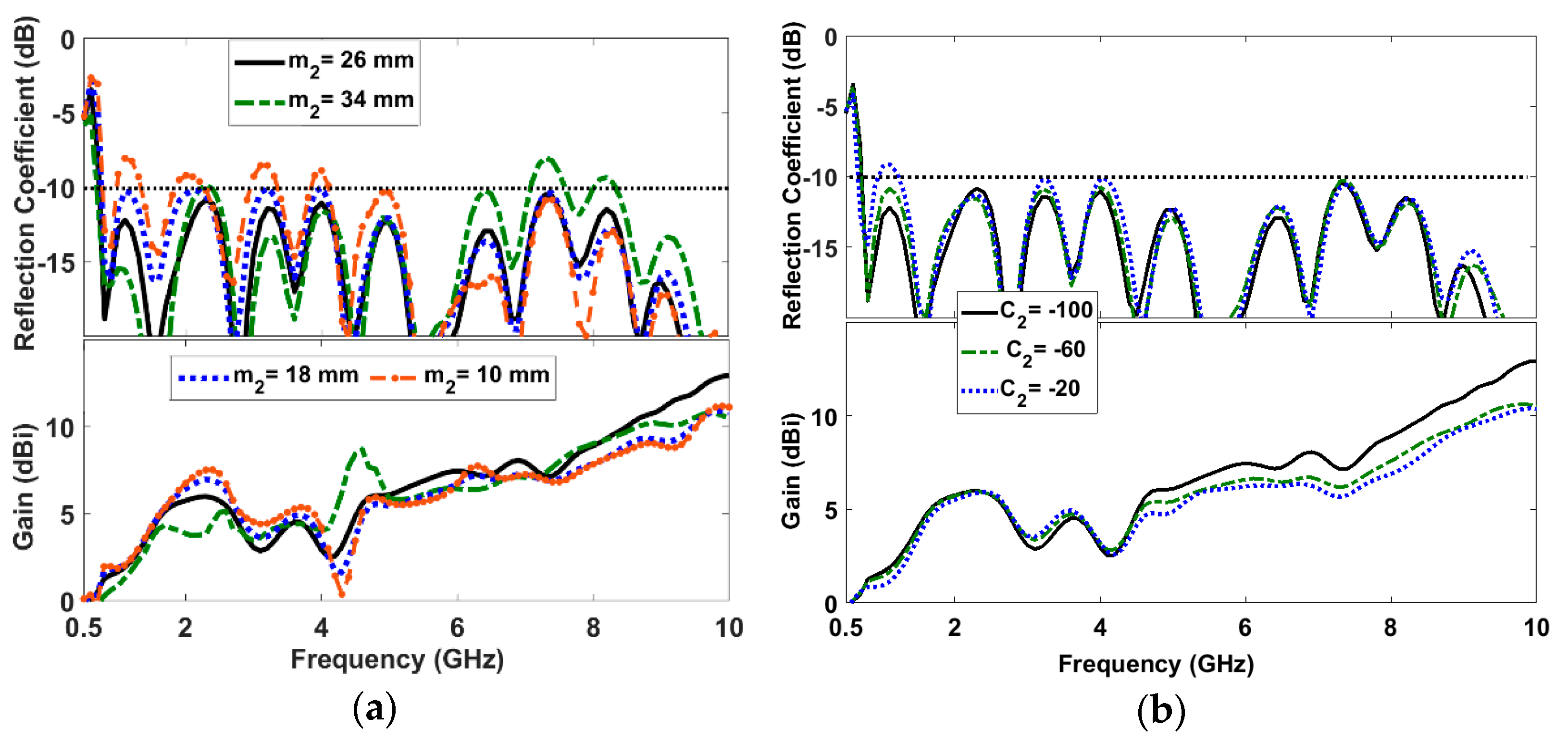
As shown in Figure 8, a parametric study on the size and degree of the exponential curves of the additional arms shows that reflection coefficient and antenna gain can be optimized by the features of the arms. This is due to the fact that the dimensions of the additional arms affect the amplitude and phase of current distribution. The size of the additional arms, as expected, has more effect at the lower edge frequency band. As shown in Figure 8a, to have a good reflection coefficient and antenna gain, the width of the additional arms need to be m2 = 26 mm. For lower values such as m2 = 10 mm, the antenna gain drops at 4.3 GHz, and the reflection gets higher values. For higher values such as m2 = 34 mm, the reflection coefficient gets worse around 7.5 GHz. Furthermore, the degree of exponential curve of the arms affects the antenna reflection at low frequencies and antenna gain at higher frequency. According to Figure 8b, this parameter needs to be set at C2 = −100 for the best performance.
3. Results and Discussion
Figure 9 shows a prototype of the fabricated AVA antenna. The proposed antenna has very simple configuration which leads to the fabrication without any complexities. Figure 10 shows the reflection coefficient of the proposed AVA antenna. Due to antenna’s simple configuration, an acceptable agreement between the simulated and measured reflection coefficient can be observed. The maximum measured reflection happens at 2.3 GHz, where a reflection coefficient of −9.4 dB is measured. The measured impedance bandwidth of 185% has been achieved over 0.72–17 GHz with acceptable radiation characteristics such as antenna gain. The gain of the proposed antenna is drawn in Figure 11. Over the measured impedance bandwidth (0.72–17 GHz), the measured antenna gain varies between 1 dBi and 12.5 dBi with the maximum gain around 10 GHz. In Figure 11, there are some discrepancies between simulation and measurement results at higher frequencies, which may be due to the measurement errors/tolerance of the measurement devices. The measured antenna gain confirms the great reliability and performance of the proposed antenna especially at the lower edge of the bandwidth.
The simulated and measured radiation patterns of the proposed antenna in both orthogonal planes ZoY (H-plane) and XoY (E-plane) at 0.7, 2.4, 5.8 and 10 GHz are shown in Figure 12. As shown, there is a good agreement between simulated and measured results in all four frequencies. At lower frequencies, the antenna has a bidirectional behavior with smooth variations. As the operating frequency increases, due to the higher order mode excitations, the unwanted ripples appear in the peripheries of the radiation patterns. The proposed antenna has the maximum gain at the main lobe in the axial direction (+Y-direction) of the tapered exponential arms. Moreover, the half-power beamwidth (HPBW) of the proposed antenna decreases as the frequency increases which results in a higher antenna gain. As seen in Figure 12, the measured cross-polarization levels of the H- and E-planes within the HPBW are at least 20 dB below the corresponding co-polarizations which indicates the extreme linearity of polarization of the fabricated AVA. This lightweight and compact antenna design provides excellent matching over a broad frequency range which makes the antenna most attractive for ultra-wideband applications. The small size of the proposed antenna makes it even more appealing for low frequency applications such as sub-six measurement setups.
The group delay is another important characteristic for an ultra-wideband antenna application which shows how the signal in time domain is distorted by the proposed AVA antenna. In this paper, two identical AVAs were placed face to face over a distance of 50 cm and the measured result in Figure 13 shows that the group delay of the proposed design is around 2 ns in the whole frequency band of interest with the variation less than ±1 ns in the most frequencies. In other words, the result demonstrates that a transmitted signal will not be harmfully affected by the proposed antenna.
Table 2 compares the proposed AVA antenna with some recent published works in the literature. As indicated, the performance of the proposed antenna in this paper is comparable with other works. The proposed antenna offers an acceptable gain all over the operating frequency band. Besides, the impedance bandwidth (0.72–17 GHz) of the proposed antenna is wider than other referred structures. The maximum gain (12.5 dBi) of the proposed antenna at X-band is higher than its counterparts. Except for the designed antenna in [19], the proposed antenna is smaller than any of other structures listed in Table 2 which are fabricated on substrates with almost higher permittivity values. It should be noted that the antenna reported in [16] has a very complicated configuration and design procedure compared to the proposed antenna structure which makes it undesirable. In addition, the fractal structures used in [16] deteriorate the linearity of the antenna due to increasing the cross-polarization.
There are several techniques to increase the Vivaldi antenna gain. Several researchers have introduced different methods to increase the antenna directivity [20,21,22,23]. Various lens structures such as metamaterial-loaded [21], fractal inspired [22], and phase adjusted [23] structures were proposed to be placed in front of the radiating area to improve the antenna directivity and radiation characteristics of Vivaldi antennas. Using one of these techniques could increase the directivity of the proposed antenna if higher gain is required.
4. Conclusions
The presented AVA antenna employs extra exponential strip arms with elliptical- shape termination, to reduce the lower edge of the operating frequency bandwidth. The decrease in the low-end operating band demonstrates that the proposed structure can effectively miniaturize the size of the Vivaldi antennas. It provides an impedance frequency bandwidth of around 185%. Moreover, the modified AVA presents an appreciable gain all over the band of interest. A good agreement between simulated and measured results illustrates that the proposed antenna is a good candidate for ultra-wideband measuring systems or other communication applications.
Author Contributions
M.M.H. has designed and fabricated the antenna structure. M.M.H. and M.S.G. have measured the antenna and wrote the manuscript. R.M. supervised the project, contributed to discussion, and reviewed the manuscript. All authors have read and agreed to the published version of the manuscript.
Funding
This work was supported by the Testforce Systems Inc., Alberta Innovative Technology Futures (AITF) and the Canadian National Science and Engineering Research Council (NSERC) under the NSERC-AITF Industrial Chair Program.
Conflicts of Interest
The authors declare no conflict of interest.
References
- Honari, M.M.; Abdipour, A.; Moradi, G. Aperture-coupled multi-layer broadband ring-patch antenna array. IEICE Electron. Expr. 2012, 9, 250–255. [Google Scholar] [CrossRef] [Green Version]
- Honari, M.M.; Mirzavand, R.; Saghlatoon, H.; Mousavi, P. Two-Layered Substrate Integrated Waveguide Filter for UWB Applications. IEEE Microw. Wirel. Compon. Lett. 2017, 27, 633–635. [Google Scholar] [CrossRef]
- Zhuge, X.; Yarovoy, A.G. A sparse aperture MIMO-SAR based UWB imaging system for concealed weapon detection. IEEE Trans. Geosci. Remote Sens. 2011, 49, 509–518. [Google Scholar] [CrossRef]
- Gibson, P.J. The Vivaldi aerial. In Proceedings of the 9th European Microwave Conference, Brighton, UK, 17–20 September 1979; pp. 101–105. [Google Scholar]
- Gazit, E. Improved design of the Vivaldi antenna. IEEE Microw. Antennas Propag. 1988, 135, 89–92. [Google Scholar] [CrossRef]
- Moosazadeh, M. Sidelobe level reduction using Teflon for a microwave and millimetre-wave antipodal Vivaldi antenna. IET Microw. Antennas Propag. 2020, 14, 474–478. [Google Scholar] [CrossRef]
- Seo, J.; Kim, J.H.; Oh, J. Semicircular Patch-Embedded Vivaldi Antenna for Miniaturized UWB Radar Sensors. Sensors 2020, 20, 5988. [Google Scholar] [CrossRef]
- Nikolaou, S.; Ponchak, G.E.; Papapolymerou, J.; Tentzeris, M.M. Conformal double exponentially tapered slot antenna (DETSA) of LCP for UWB application. IEEE Trans. Antennas Propag. 2006, 54, 1663–1669. [Google Scholar] [CrossRef]
- Eichenberger, J.; Yetisir, E.; Ghalichechian, N. High-Gain Antipodal Vivaldi Antenna with Pseudoelement and Notched Tapered Slot Operating at (2.5 to 57) GHz. IEEE Trans. Antennas Propag. 2019, 67, 4357–4366. [Google Scholar] [CrossRef]
- Yin, Z.; He, G.; Yang, X.; Gao, S. Miniaturized Ultrawideband Half-Mode Vivaldi Antenna Based on Mirror Image Theory. IEEE Antennas Wirel. Propag. Lett. 2020, 19, 695–699. [Google Scholar] [CrossRef]
- Wang, N.B.; Jian, Y.C.; Song, Y.; Zhang, L.; Zhang, F.S. A microstrip-fed logarithmically tapered slot antenna for wideband application. J. Electromagn. Waves Appl. 2009, 23, 1335–1344. [Google Scholar] [CrossRef]
- Abbosh, A.M. Miniaturized microstrip-fed tapered-slot antenna with ultrawideband performance. IEEE Antennas Propag. Lett. 2009, 8, 690–692. [Google Scholar] [CrossRef] [Green Version]
- Li, T.; Rao, Y.; Niu, Z. Analysis and design of UWB Vivaldi antenna. In Proceedings of the International Symposium on Microwave, Antenna, Propagation and EMC Technologies for Wireless Communications, Hangzhou, China, 16–17 August 2007; pp. 579–581. [Google Scholar]
- Dastranj, A. Wideband antipodal Vivaldi antenna with enhanced radiation parameters. IET Microw. Antennas Propag. 2015, 9, 1755–1760. [Google Scholar] [CrossRef]
- Nassar, I.T.; Weller, T.M. A novel method for improving antipodal Vivaldi antenna performance. IEEE Trans. Antenna Propag. 2015, 63, 3321–3324. [Google Scholar] [CrossRef]
- Teni, G.; Zhang, N.; Qiu, J.; Zhang, P. Research on a Novel Miniaturized Antipodal Vivaldi Antenna with Improved Radiation. IEEE Antennas Wirel. Propag. Lett. 2013, 12, 417–420. [Google Scholar] [CrossRef]
- Wang, Z.; Yin, Y.; Wu, J.; Lian, R. A miniaturized CPW-fed antipodal Vivaldi antenna with enhanced radiation performance for wideband applications. IEEE Antennas Wirel. Propag. Lett. 2016, 15, 16–19. [Google Scholar] [CrossRef]
- Fei, P.; Jiao, Y.C.; Hu, W.; Zhang, F.S. A miniaturized antipodal Vivaldi antenna with improved radiation characteristics. IEEE Antennas Wirel. Propag. Lett. 2011, 10, 127–130. [Google Scholar]
- Siddiqui, J.Y.; Antar, Y.M.M.; Freundorfer, A.P.; Smith, E.C.; Morin, G.A.; Thayaparan, T. Design of an ultrawideband antipodal tapered slot antenna using elliptical strip conductors. IEEE Antennas Wirel. Propag. Lett. 2011, 10, 251–254. [Google Scholar] [CrossRef]
- Biswas, B.; Ghatak, R.; Poddar, D.R. A Fern Fractal Leaf Inspired Wideband Antipodal Vivaldi Antenna for Microwave Imaging System. IEEE Trans. Antenna Propag. 2017, 65, 6126–6129. [Google Scholar] [CrossRef]
- Cheng, H.; Yang, H.; Li, Y.; Chen, Y. A Compact Vivaldi Antenna with Artificial Material Lens and Sidelobe Suppressor for GPR Applications. IEEE Access 2020, 8, 64056–64063. [Google Scholar] [CrossRef]
- Karmakar, A.; Bhattacharjee, A.; Saha, A.; Bhawal, A. Design of a fractal inspired antipodal vivaldi antenna with enhanced radiation characteristics for wideband applications. IET Microw. Antennas Propag. 2019, 13, 892–897. [Google Scholar] [CrossRef]
- Sang, L.; Wu, S.; Liu, G.; Wang, J.; Huang, W. High-Gain UWB Vivaldi Antenna Loaded With Reconfigurable 3-D Phase Adjusting Unit Lens. IEEE Antennas Wirel. Propag. Lett. 2020, 19, 322–326. [Google Scholar] [CrossRef]
Figure 1.
Antipodal Vivaldi antenna configuration with (a) different widths of tapered strips, and (b) their reflection coefficient and gain.
Figure 1.
Antipodal Vivaldi antenna configuration with (a) different widths of tapered strips, and (b) their reflection coefficient and gain.

Figure 2.
The proposed Vivaldi antenna configuration.

Figure 3.
(a) Surface current distribution on the proposed antenna structure with/without additional strip arms at the frequency of (a) 1.6 GHz, and (b) 0.8 GHz.
Figure 3.
(a) Surface current distribution on the proposed antenna structure with/without additional strip arms at the frequency of (a) 1.6 GHz, and (b) 0.8 GHz.

Figure 4.
Reflection coefficient of the AVA (Antipodal Vivaldi antenna) structure with arms (proposed antenna) and without arms (conventional antenna).
Figure 4.
Reflection coefficient of the AVA (Antipodal Vivaldi antenna) structure with arms (proposed antenna) and without arms (conventional antenna).

Figure 5.
Reflection coefficient of the AVA structure with arms (proposed antenna) and without arms (conventional antenna), and only strip arms.
Figure 5.
Reflection coefficient of the AVA structure with arms (proposed antenna) and without arms (conventional antenna), and only strip arms.

Figure 6.
Electric field distribution above the top layer of the proposed antenna structure at (a) 0.8 GHz, (b) 1.6 GHz, and (c) 4 GHz.
Figure 6.
Electric field distribution above the top layer of the proposed antenna structure at (a) 0.8 GHz, (b) 1.6 GHz, and (c) 4 GHz.

Figure 7.
Gain of the AVA structure with arms (proposed antenna) and without arms (conventional antenna).
Figure 7.
Gain of the AVA structure with arms (proposed antenna) and without arms (conventional antenna).

Figure 8.
Reflection coefficient and antenna gain for (other parameters are constant) (a) different width and (b) the degree of exponential curve of the additional arms.
Figure 8.
Reflection coefficient and antenna gain for (other parameters are constant) (a) different width and (b) the degree of exponential curve of the additional arms.

Figure 9.
Photograph of fabricated antenna: (a) top layer and (b) bottom layer.

Figure 10.
Reflection coefficient of the proposed antenna.

Figure 11.
Gain of the proposed antenna.

Figure 12.
Simulated and measured radiation patterns of the designed antenna in ZY (H-plane) and XY (E-plane) at (a) 0.7 GHz, (b) 2.4 GHz, (c) 5.8 GHz and (d) 10 GHz.
Figure 12.
Simulated and measured radiation patterns of the designed antenna in ZY (H-plane) and XY (E-plane) at (a) 0.7 GHz, (b) 2.4 GHz, (c) 5.8 GHz and (d) 10 GHz.


Figure 13.
Measured group delay of the proposed antenna.


Table 1.
Final optimum parameter values of the proposed antenna.
| Parameter | Value | Parameter | Value |
|---|---|---|---|
| Ws | 158 mm | m1 | 22 mm |
| Ls | 125 mm | m2 | 26 mm |
| Wstrip | 66 mm | n1 | 7 mm |
| Wt | 2 mm | n2 | 11 mm |
| Wg | 32 mm | a2 | −80 mm |
| Lg | 10 mm | b2 | −80 mm |
| s | 59 mm | c2 | −100 mm |
| d | 16 mm | d2 | −100 mm |
| P | 7 mm | ||
Table 2.
Comparison between some AVAs and TSAs (tapered slot antennas) in literature and the proposed antipodal Vivaldi antenna.
Table 2.
Comparison between some AVAs and TSAs (tapered slot antennas) in literature and the proposed antipodal Vivaldi antenna.
| Ref No. | ɛr | Operating Frequency (GHz) | Impedance BW (%) | Min and MaxGain (dBi) | |
|---|---|---|---|---|---|
| [15] | 4.5 | 0.67 × 0.89 | 4–30 | 152 | 5&7 |
| [16] | 2.6 | 0.39 × 0.4 | 1.3–17 | 171 | 3.5&9.3 |
| [17] | 4.4 | 0.39 × 0.48 | 2.4–14 | 141 | 3.7&10 |
| [18] | 3.5 | 0.37 × 0.43 | 0.8–9.8 | 170 | 0&10.5 |
| [19] | 4.4 | 0.22 × 0.27 | 1.3–20 | 176 | −2&10 |
| This work | 2.5 | 0.3 × 0.38 | 0.72–17 | 184 | 1&12.5 |
λ0: Free space wavelength at the lowest operating frequency.
Publisher’s Note: MDPI stays neutral with regard to jurisdictional claims in published maps and institutional affiliations. |
© 2021 by the authors. Licensee MDPI, Basel, Switzerland. This article is an open access article distributed under the terms and conditions of the Creative Commons Attribution (CC BY) license (http://creativecommons.org/licenses/by/4.0/).
Share and Cite
MDPI and ACS Style
Honari, M.M.; Ghaffarian, M.S.; Mirzavand, R. Miniaturized Antipodal Vivaldi Antenna with Improved Bandwidth Using Exponential Strip Arms. Electronics 2021, 10, 83. https://doi.org/10.3390/electronics10010083
AMA Style
Honari MM, Ghaffarian MS, Mirzavand R. Miniaturized Antipodal Vivaldi Antenna with Improved Bandwidth Using Exponential Strip Arms. Electronics. 2021; 10(1):83. https://doi.org/10.3390/electronics10010083
Chicago/Turabian StyleHonari, Mohammad Mahdi, Mohammad Saeid Ghaffarian, and Rashid Mirzavand. 2021. "Miniaturized Antipodal Vivaldi Antenna with Improved Bandwidth Using Exponential Strip Arms" Electronics 10, no. 1: 83. https://doi.org/10.3390/electronics10010083
Note that from the first issue of 2016, this journal uses article numbers instead of page numbers. See further details here.