
A Wireless Covert Channel Based on Dirty Constellation with Phase Drift


Institute of Communications Systems, Faculty of Electronics, Military University of Technology, 00-908 Warsaw, Poland
*
Author to whom correspondence should be addressed.
Electronics 2021, 10(6), 647; https://doi.org/10.3390/electronics10060647
Submission received: 31 December 2020
/
Revised: 2 March 2021
/
Accepted: 8 March 2021
/
Published: 11 March 2021
(This article belongs to the Special Issue Cybersecurity and Data Science)
Abstract
:Modern telecommunications systems require the use of various transmission techniques, which are either open or hidden. The open transmission system uses various security techniques against its unauthorized reception, and cryptographic solutions ensure the highest security. In the case of hidden transmissions, steganographic techniques are used, which are based on the so-called covert channels. In this case, the transparency and stealth of the transmission ensure its security against being picked up by an unauthorized user. These covert channels can be implemented in multimedia content, network protocols, or physical layer transmissions. This paper focuses on wireless covert channels. We present a novel method of steganographic transmission which is based on phase drift in phase-shift keying or quadrature amplitude modulation (QAM) and is included in the so-called dirty constellation techniques. The proposed approach is based on the drift correction modulation method, which was previously used in the watermarking of audio-signals. The developed solution is characterized by a variable bit rate, which can be adapted to the used modulation type and transmission conditions occurring in radio channels. In the paper, we present the method of generating and receiving hidden information, simulation research, and practical implementation of the proposed solution using the software-defined radio platform for selected QAM.
1. Introduction
The increase in capacity is one feature of emerging communication systems, including the fifth (5G) and sixth generation (6G) systems. This is due to the use of wider radio channels, their aggregation, or the use of higher frequency bands, i.e., millimeter, terahertz, or optical waves. A wider band of transmitted signals also gives greater possibilities to implement covert data transmission. Hence, the greater interest in searching for new steganographic methods is more evident [1].
Steganography consists in transmitting information to make the act of transmission undetectable. Unlike cryptographic information, whose content is encrypted, the very existence of steganographic information is concealed. Steganographic information, which is also known as covert information, requires a carrier—or, in other words, a cover. The simplest carrier scenario uses photos [2], audio [3] or video signals [4] (multimedia steganography) to hide additional information. One of the important steganography applications includes creating covert channels. The term “covert channel” was coined by Butler W. Lampson as: “… any communication channel that can be exploited by a process to transfer information in a manner that violates the systems security policy …” [5]. B.W. Lampson focused on the exchange of data between programs. Nowadays, it is assumed that any method of communication used to illegally transmit information, which violates the system security policy, is a covert channel.
Data security is generally ensured by the flow control between the sender and authorized recipient. Though wired networks commonly use firewalls, security can be violated by covert channels. In this case, the information can be embedded by manipulating the packet timing information (i.e., covert timing channel) [6,7,8,9,10] or putting some bits into the packet headers (i.e., covert storage channel) [11,12]. So-called network steganography understood in a broad sense can be applied to both physical layer symbol frames [13], protocols of medium access control (MAC) [14], routing [15], networks [16], or higher layers, e.g., Transmission Control Protocol/Internet Protocol (TCP/IP) [11], Hypertext Transfer Protocol (HTTP) [17], and Domain Name System (DNS) [18]. These methods can be applied in homogeneous wired and wireless networks (e.g., accordant with the IEEE 802.11 standard [12,13]) as well as in heterogeneous ad hoc networks (e.g., [15]). Along with the development of network steganography techniques, we may notice novel solutions of network steganalysis, e.g., [19].
Contrary to the wired network, the wireless physical layer gives further possibilities for implementing the covert communication. In general, the wireless covert channel has its advantages and disadvantages [20]. In wired communications, it must be ensured that the channel is not distorted by network devices on either side of the covert channel. In wireless communication, the range between two points is limited by the transmitter power and the parameters of the receiver, e.g., its sensitivity. In this case, the steganography can relate to both radio and optical (e.g., [21,22]) wired and wireless communications. The further analysis focuses on wireless radio communication steganography.
In wireless communications, we deal with noise, interference, and fading that can seriously degrade transmission capabilities. In this case, it is worth introducing the terms “premodulation” and “postmodulation” steganography [23]. Pemodulation steganography is related to the bit structure change of the transmitted cover information. In contrast, postmodulation steganography refers directly to the physical parameter change of the transmitted waveforms. The proposed method presented in this paper is included in the category of wireless postmodulation steganography.
In the literature, we can find many ways to implement covert channels based on the physical layer. For N-ary frequency-shift keying (FSK) signals, E. Szczepaniak et al. proposed hiding information in a frequency drift and offset [24]. For orthogonal frequency-division multiplexing (OFDM) signals, different methods may be used, e.g., virtual carriers [25], the modification of training sequences, the covert-data-dependent shift of the signal carrier frequency, or using changes in the cyclic prefix [26]. The disadvantage of all these solutions is the low bit rates obtained. In contrast, theoretical approaches for the direct sequence spread spectrum (DSSS) and frequency-hopping spread spectrum (FHSS) techniques are shown in [27]. The DSSS and FHSS techniques are used primarily in military communication systems due to the low probability of detection/intercept (LPD/LPI) [28]. However, in [27], B.A. Bash et al. do not show the practical implementation of the proposed solutions. In the literature, we can also find steganographic solutions based on spatial multiplexing. P. Cao et al. propose to use multiple-input multiple-output (MIMO) technologies to create covert channels [29]. In this case, artificial noise modulated from secret messages is distributed as Gaussian channel noise, which increases the undetectability of a hidden transmission. Additionally, to improve its transparency, P. Cao et al. propose to modify the channel state information (CSI) parameters to reduce their correlation [29].
For modulations with constant points in their constellations, such as N-ary phase-shift keying (PSK) or quadrature amplitude modulation (QAM), dedicated steganography techniques are applicable. These methods are based on hiding information around the core points of the modulation constellation, and they seem more practical and convenient. For example, [30] describes the embedding of points in a constellation offset from the original points and adopts the term “dirty constellation”. A similar solution defined as “constellation shaping modulation” is proposed in [31], although it focuses more on increasing covertness. In comparison to [30], the approach of [31] improves nondetectability at the expense of reliability degradation measured by bit error rate (BER). Creating a covert channel by superimposing pseudonoise asymmetric shift keying (PN-ASK) modulation was proposed in [32]. In this case, covert symbols are mapped by shifting the amplitude of primary symbols to a high order amplitude-phase modulation on a carrier constellation. The main drawback of this solution is limitations to the only phase-modulated cover signals. Moreover, multilevel amplitude modulation of the covert signal causes decreasing security (increasing detectability). Considering the high concentration of radio emissions in the available radio spectrum and the ever-growing number of used transceiver devices, this type of steganographic technique seems to be worth attention, research, and development. Considering the fact that [31] and [32] basically made a comparative analysis of [30], in this paper, we similarly focused on developing a novel idea of dirty modulation.
In this paper, we present a novel dirty modulation that is based on a phase drift and dedicated to the N-ary PSK or QAM signals. A similar solution, but based on the frequency drift in the N-ary FSK signals, is presented in [24]. The idea of hiding information in the drift of radio signal parameters is based on the drift correction modulation (DCM) method [33], which was used to hide information in audio signals. In this case, Z, Piotrowski also used the phase drift in the OFDM signal, which was then psychoacoustic corrected and added to the audio cover [33]. In the developed solution, we hide the information in a determined phase drift around the current constellation point of the transmitted radio signal. The phase difference constituting the drift step and the centroid distance from the constellation points are the parameters of the developed method. These parameters may be selected adaptive to the modulation type or transmission conditions. The modulation choice has a significant impact on the number of points (i.e., transmitted symbols) in its constellation, which translates into the distances of neighboring points on it. The influence of the transmission conditions, i.e., a signal-to-noise ratio (SNR), translates into a detection interference of the symbols and hidden subsymbols in the received signal. During the transmission, the received symbols (i.e., constellation points) change. Hence, phase drift detection, and thus steganalysis of the developed method, is more difficult than other dirty modulations. This is due to the fact that we do not set constant points in the constellation as the place of reading the subsymbol of covert transmission, but we hide the information in the drift step, i.e., the phase difference of the consecutive constellation points. This proves the originality of the proposed solution in comparison with other dirty modulation or wireless postmodulation steganography methods available in the literature.
In the paper, we present a methodology for generating and receiving the covert channels based on the dirty constellation with the phase drift and compare it with [30] as others have done. We want to emphasize that in addition to the simulation analysis typical for this kind of paper, we also present the first lab tests. In this practical implementation, we conducted tests using hardware and covert transmission over a real radio channel. To increase the SNR of the covert signal, multiple repetitions of the hidden subsymbols on the transmitting side and coherent averaging [34] of the successive drift phase differences on the receiving side shall be applied. This reduces the resulting bit rate of the covert transmission in the proposed method. However, this approach allows adaptation to the transmission conditions occurring in the radio channel. The proposed method will be used in future radio communication systems, including 5G networks dedicated to military applications. We plan to use it in the upcoming European Defense Agency (EDA) project, codenamed SOFTANET, for the hidden data layer in the wireless part of a software-defined network (SDN) [35,36,37]. It is in line with the trend, visible in the literature, of using steganography in 5G systems and networks, e.g., [21,38].
Analyzing the security system trends, including those based on cryptography and steganography, we see numerous threats to the existing techniques. They result from the increasing use of artificial intelligence (AI) algorithms [39,40] and quantum technologies [41,42] in security breach systems. On the other hand, these technologies may also be potential development directions of the security systems. Currently, the literature offers numerous solutions, including steganographic ones, which are based on modern AI (such as machine learning (ML) [43,44]) and quantum technologies [45,46] increasing the robustness, undetectability, and efficiency of emerging security and data transmission systems. In the case of the developed method, in the near future we want to use these ML techniques for a time-varying selection of the DCM parameters, which may increase its robustness, transparency, and the bitrate of the covert transmission.
Based on an approach presented in [47], we want to summarize the contribution of this paper. This research possesses various contributions in the domain of wireless steganography, watermarking, and wide-sense security of future wireless systems.
- First, a DCM-based novel dirty constellation has been proposed, which can be used in N-ary PSK and QAM signals. The previous DCM solution [33] was dedicated to watermarking audio signals using the OFDM.
- Second, based on simulation studies, the impact of the parameter variability of the developed method on its detection possibility using statistical analysis techniques has been shown.
- Third, the efficiency of the developed method and its comparison with another dirty constellation technique [30] have been presented.
- Lastly, the possibility of the practical implementation of the proposed solution has been shown, which gives a premise for its practical use in hidden data layer creation in SDN for the SOFTANET project and in future wireless systems and networks.
The remainder of the paper is as follows. Section 2 describes the idea of dirty constellation based on [30]. Our solution based on phase drift is presented in Section 3. In Section 4, we introduce the evaluation criteria of the covert channels. Using them, we analyze the developed dirty constellation based on the simulation and measurement approaches in Section 5 and Section 6, respectively. Section 7 contains the paper summary.
2. Concept of Dirty Constellation
The main idea for creating covert channels based on the dirty modulation results from the fact that the received signals do not have an ideal constellation. Instead, we see a radio channel and parameter imperfection caused by both the transmitting and receiving devices’ influence on blurring (spreading) the received-signal constellations. This effect translates to phase and amplitude distortions and ultimately to an increase in BER.
To increase the bandwidth efficiency, the N-ary PSK or QAM modulations are commonly used in telecommunications together with OFDM access. A time-frequency structure (waveform) of the OFDM signal provides a lot of space and possibilities for creating the covert channel, e.g., [26]. The suggested solutions include the use of the OFDM symbol waveform. When analyzing the QAM signal, the covert channel is provided based on the errors, which are the differences between the theoretical and the real points of the constellation. This results from environmental noise and hardware impairments. The theoretical, finite M number of constellation points corresponding to the N-ary PSK or QAM, in practice, has the form of the finite number of constellation point sets concentrated around the theoretical values without any distortions. Therefore, the channel will remain “hidden” as long as it is perceived as a noisy version of the carrier signal (i.e., the PSK or QAM signal) by the third uninformed party. It is important that after applying the covert information, the carrier remains distorted as little as possible so that the reception of the primary signal should be error-free.
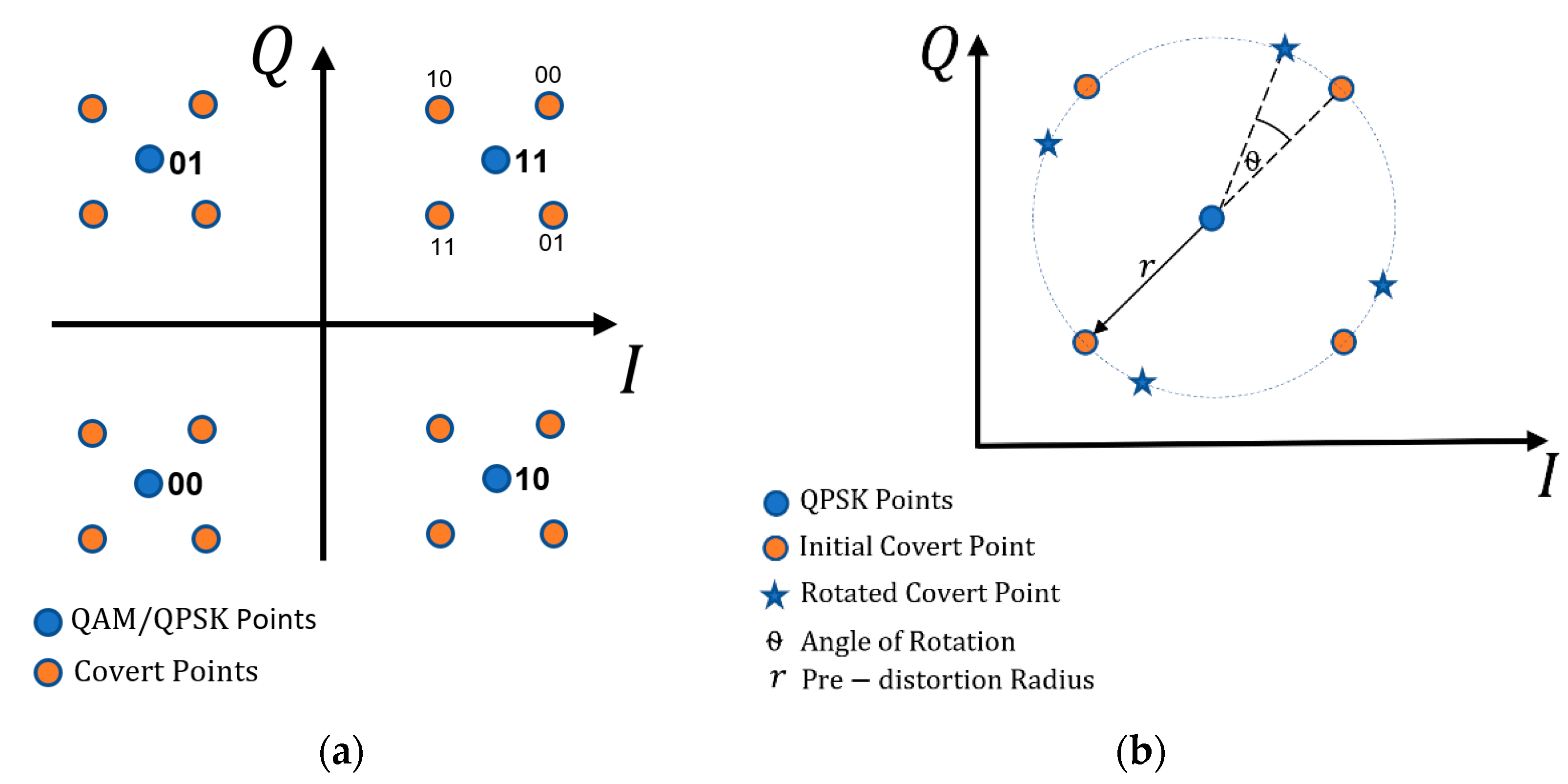
It is the idea of using the dirty constellation proposed in [30]. The bits of covert information are mapped into additional constellation points placed around the base (i.e., carrier) constellation points, which is illustrated in Figure 1. According to the assumption, these additional constellation points are perceived as noise/error by the uninformed user. The value of the covert information symbol is defined in relation to the carrier constellation point.
The carrier constellation is marked with blue circles, while the constellation related to the covert subsymbols (i.e., covert message bits) is marked with red ones. The probability of detection by adversaries is limited by reducing the predistortion radius, r. In addition, r can be changed (e.g., randomly) within a preset range. A. Dutta et al. for masking purposes used the fact that the QAM signal is transmitted by using the OFDM [30]. Therefore, each unused OFDM subcarrier may be a masking element providing more random (noiselike) in relation to the general character of the covert transmission. Additionally, A. Dutta et al. propose inserting angle rotation, θ, for successive OFDM harmonics, to increase the number of the received QAM constellation states for the subcarrier set. However, it does not change the number of constellation points if only one of the OFDM subcarriers is analyzed.
3. Phase Drift-Based Dirty Constellation
The developed dirty constellation with the phase drift is based on the DCM [33]. The DCM solution was used to create a watermark in audio files. The covert information is represented in monotonic phase changes of the selected signal harmonics. The mth harmonic selected for steganography is expressed by the following formula [33]
where and represent amplitude and frequency of the mth signal, respectively, is an initial phase and is the preset phase drift carrying covert information.
In the DCM detector, the signal is subjected to the phase angle scanning procedure, which results in finding the maximum of the virtual fringe module As shown in [33], the DCM demonstrates good steganographic properties.
In our approach, we adopted the DCM for creating the dirty constellation of the steganographic channel. For further considerations, we assume that the QAM signal (without the use of the OFDM) is the carrier (cover) of the hidden transmission. The proposed method uses a covert symbol represented by the K ≥ 2 phase drifts of the successive cover constellation points. Therefore, the symbols of the QAM can carry P/K covert symbols.
For the N-ary QAM, the single constellation point is defined in the complex form:
where and are the amplitude and phase of the nth constellation point.
A single M-ary covert message adopts the form of a K-component complex vector:
where and are the centroid distance and phase drift step for the proposed dirty constellation, respectively, and is a random initial phase, which does not change when the covert symbol is in progress.
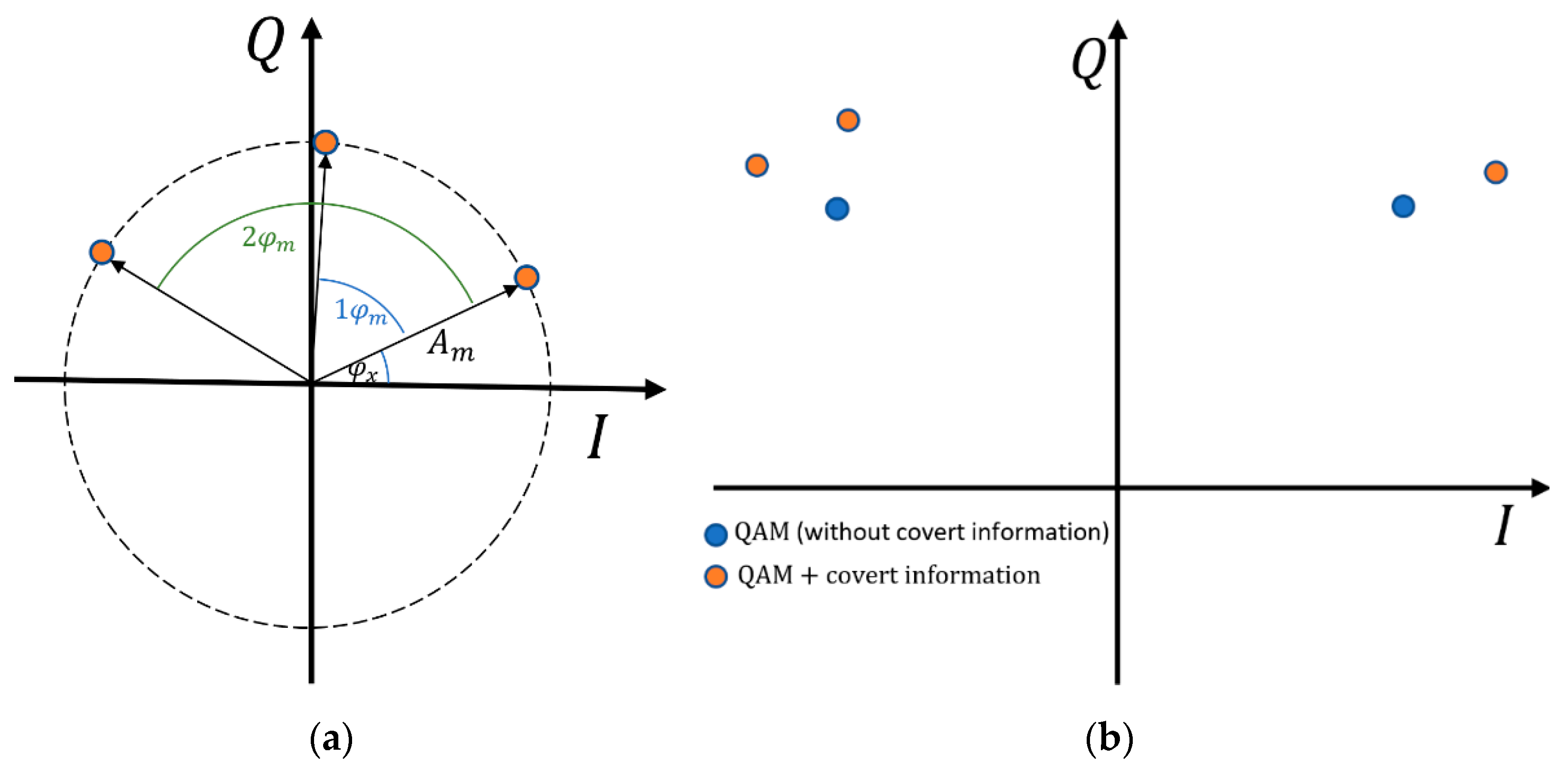
Steganographic information is created by combining (adding) two successive K cover symbols with successive covert message symbols (i.e., vectors ). An example of creating hidden information for a single covert symbol and is presented in Figure 2.
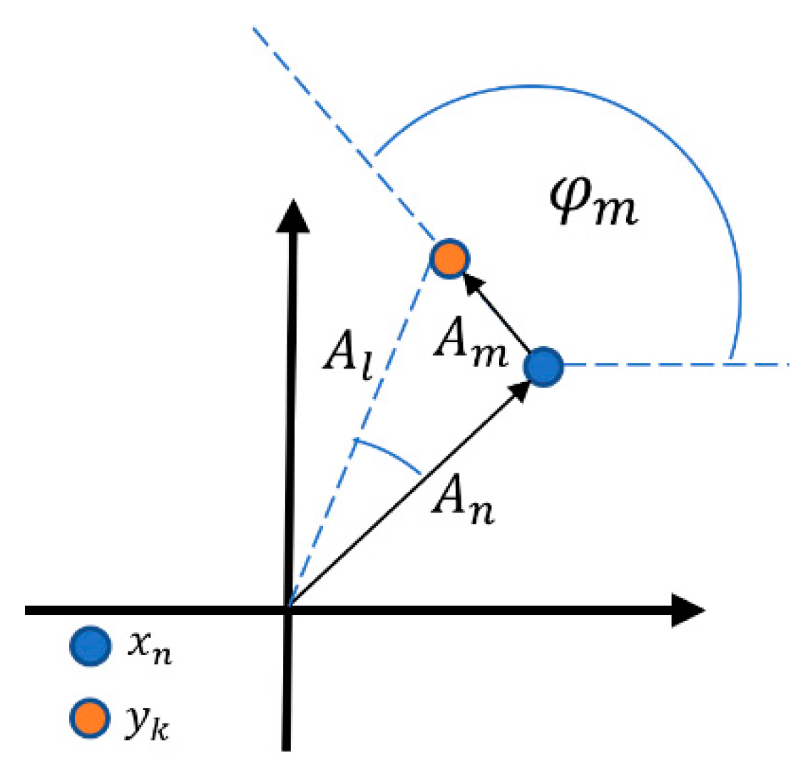
Possible phase increments correspond to the M-ary DCM. As a result, we receive new constellation points in the following form:
where and mean the amplitude and phase of the new point in the constellation relative to the origin of the IQ coordinate system, respectively, which is depicted in Figure 3.
The parameters and are limited by the following relationships:
Equations (5) and (6) mean that the maximum distortions of module and phase of carrier symbols might be and , respectively. These values describe the degradation level of the original signal by the DCM. On the one hand, it handicaps the recreation of the cover information. On the other hand, it shows the possibility of detecting stenographic transmission.
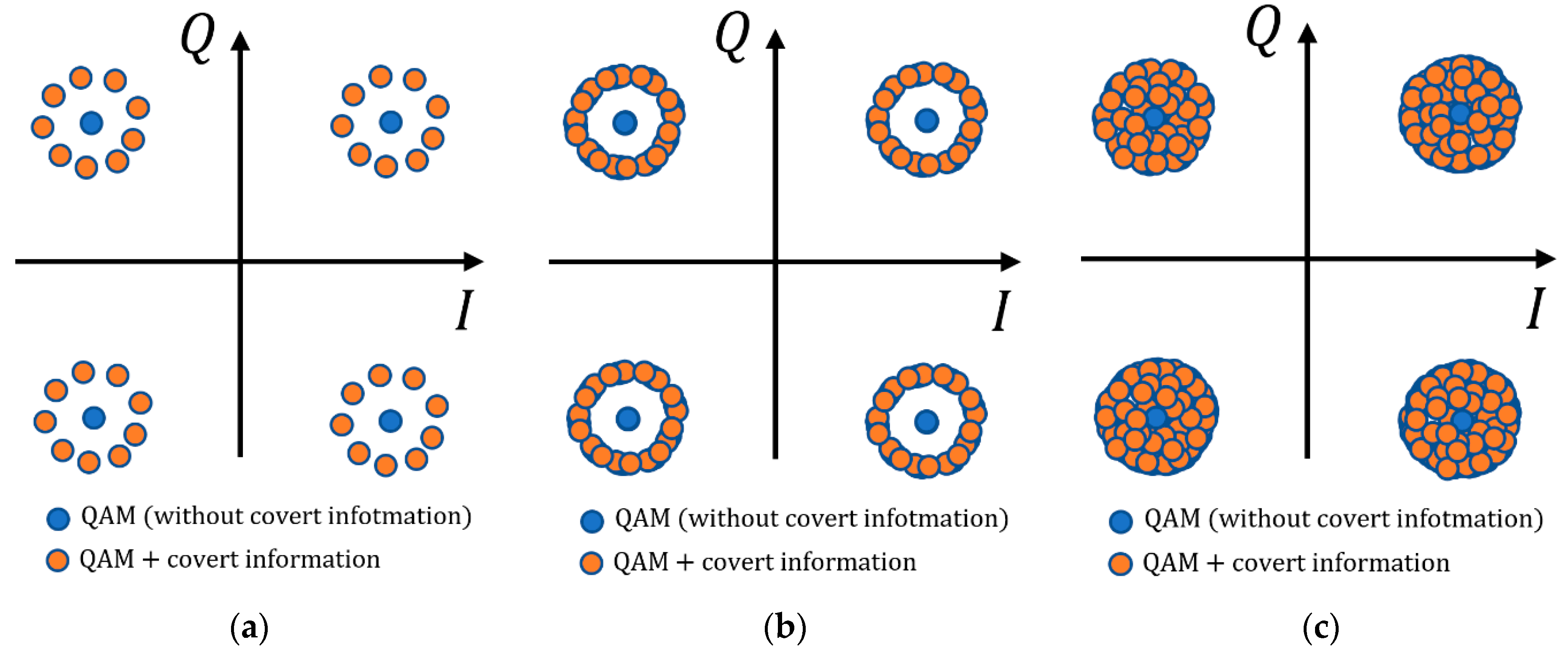
The proposed approach allows us to better hide the steganographic channel than the method based on the dirty constellation shown in [30]. This is possible thanks to the random initial phase the adaptive selection of the centroid distance and the phase drift step . In the general case, the parameters and could also be random within defined ranges. An example of the phase drift-based dirty constellation for long bit strings is presented in Figure 4.
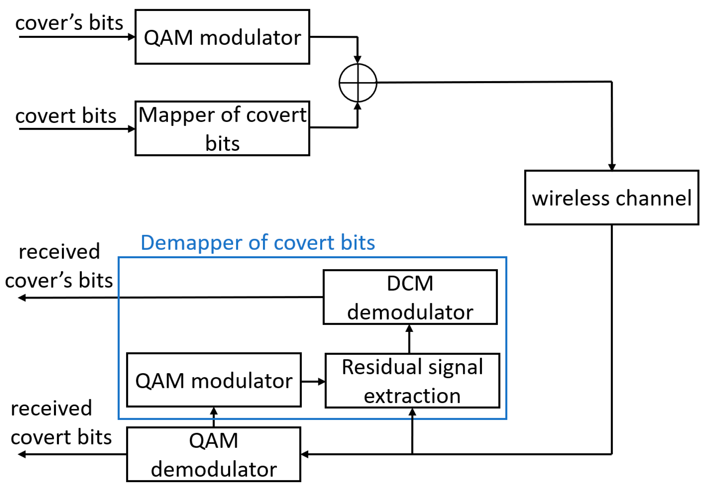
The transceiver (transmitter–receiver) system is shown in Figure 5. This approach is similar to the framework of wireless covert channel proposed in [31] (Figure 4, p. 5).
In the transmitter system, the fixed phase drift is added to the cover constellation obtained at the output of the QAM modulator. The DCM mapper is used to assign vector After putting together vector with carrier constellation points the transmission adopts the steganographic form.
In the receiver system, if necessary, the detection of the overt signal (cover) is performed using a traditional QAM demodulator. By contrast, information from the covert channel is received by using the so-called DCM demapper. In the first instance, this system determines the residual signal, which is the difference between the constellation points of the carrier and the received signal, In more detail, it is an assigned complex vector with error caused by the signal transmission through the radio channel
where and are the amplitude and phase of the covert symbols in the received signal.
The DCM demodulator performs the phase angle scanning procedure. In this case, based on the knowledge of the possible angle values used in the steganographic transmitter, it calculates the values for each as follows
The maximum value of the module for a given corresponds to the assigned symbol of the covert information. It is worth noting that according to Equation (8), the value can be treated as the number of averages performed for a single covert symbol. By providing coherent averaging [34] of the hidden subsymbols, we obtain an increase in the detection gain of covert transmissions according to [33]. The multiplexing use of the hidden symbols may increase the effectiveness of its correct detection. In a similar way, the oversampling application of various credit-related datasets significantly improves the performance of a credit default prediction model presented in [47].
4. Evaluation Criteria for Covert Channels
To evaluate the covert channel efficiency, we may use the following parameters:
- Covert channel detectability defined by the detection probability,
- Cost understood as the carrier signal distortion,
- Transmission rate and BER in the covert channel.
In steganography, the most important parameter is its transparency, understood as the undetectability of the transmission existence by outside users (i.e., third parties). It should be highlighted that an easily detectable covert channel is completely irrelevant, even if it provides a high transmission rate.
The limit values of the cost function are usually defined for a given cover transmission standard by an error vector magnitude (EVM). The EVM for a signal with a covert channel is the cumulative result of influencing the transmitter systems and distortions introduced by the covert channel. For example, Table 1 contains the EVMs for quadrature PSK (QPSK) and N-ary QAM in the 5G systems [48] (Table 6.5.2.2-1, p. 48).
There are no clear criteria defining the channel detectability. The presence of a covert channel can be indicated when an exceedingly high EVM level is observed or the high level is more frequent (i.e., higher than assumed). This was detected in the statistical studies, including signal histograms.
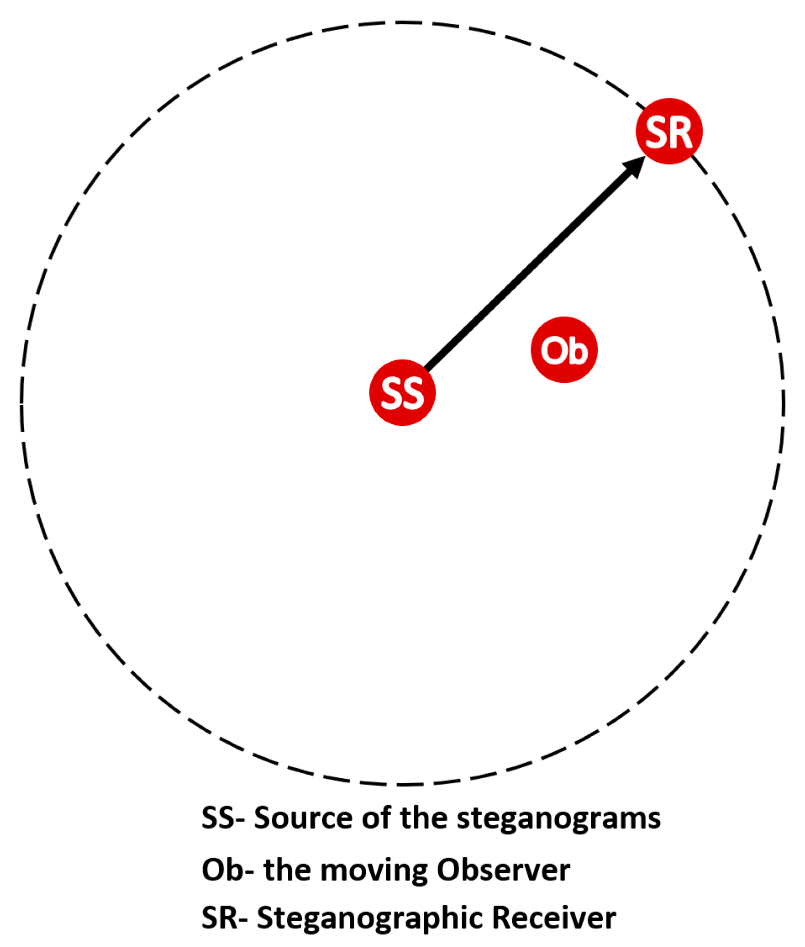
Instead of determining the statistical values of the signal at the receiver input by using the classic prisoner problem proposed by Simmons [49] we may use the scheme of a moving observer [50] to assess the detection. In this model, Alice, Wendy, and Bob correspond to the steganographic source (SS), observer (Ob), and steganographic receiver (SR), respectively. Figure 6 illustrates the analyzed scenario.
In this model, detecting the covert channel depends on the distance from the SS. As the distance increases, the influence of the radio channel intensifies. However, in the case of postmodulation steganography, there is a situation in which the mobile Ob, being near the SR, is able to detect steganographic emission with a high probability. With the increase in SNR, it is easier to identify the regularity of covert information constellation. By moving away from the SS, noise and other propagation phenomena occurring in the real channel make it difficult to detect the emission, as well as its reception, understood as the reproduction of the bitstream [50].
When considering the detectability of the covert channel as a priority, the proposed solution offers several basic properties:
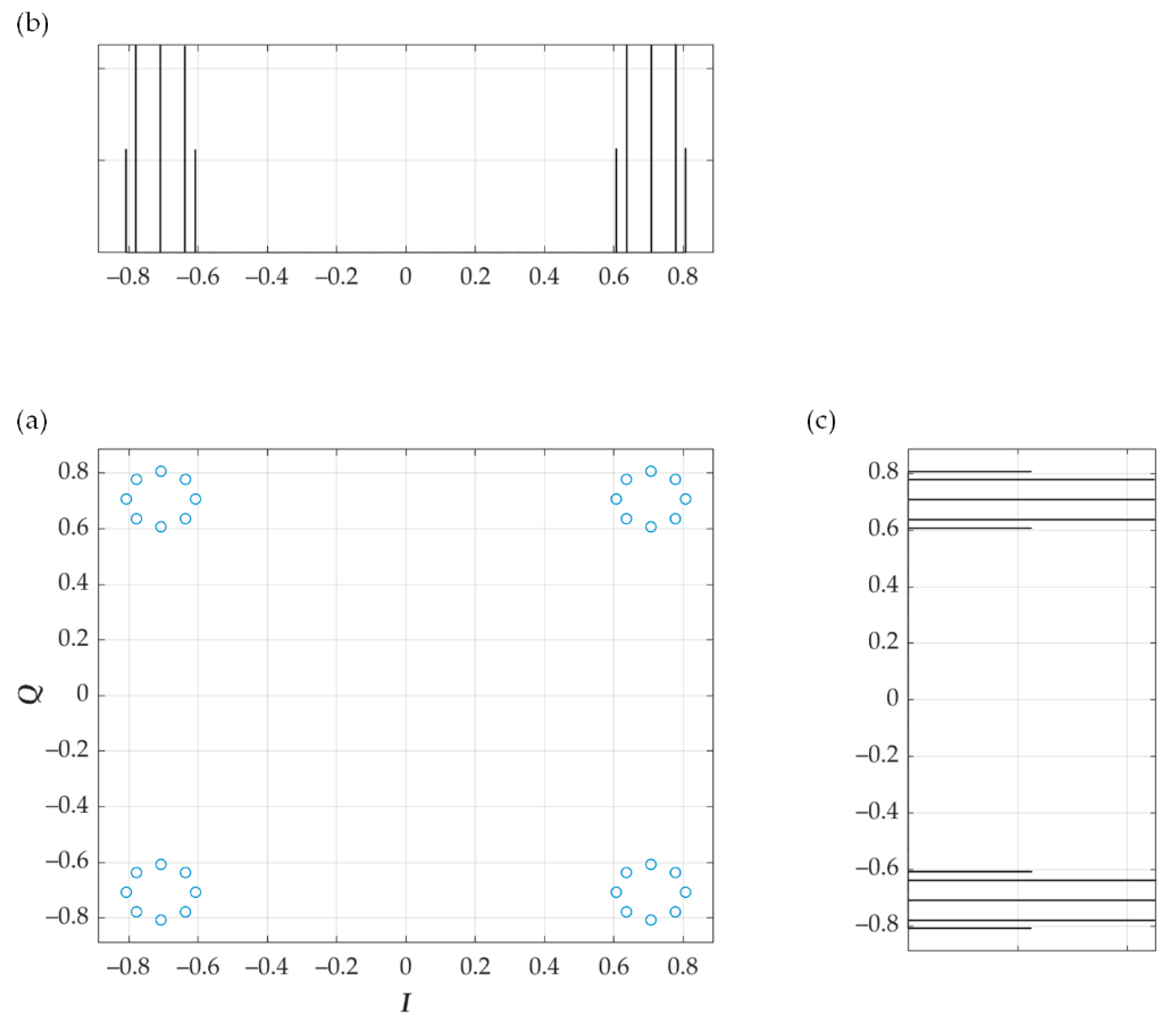
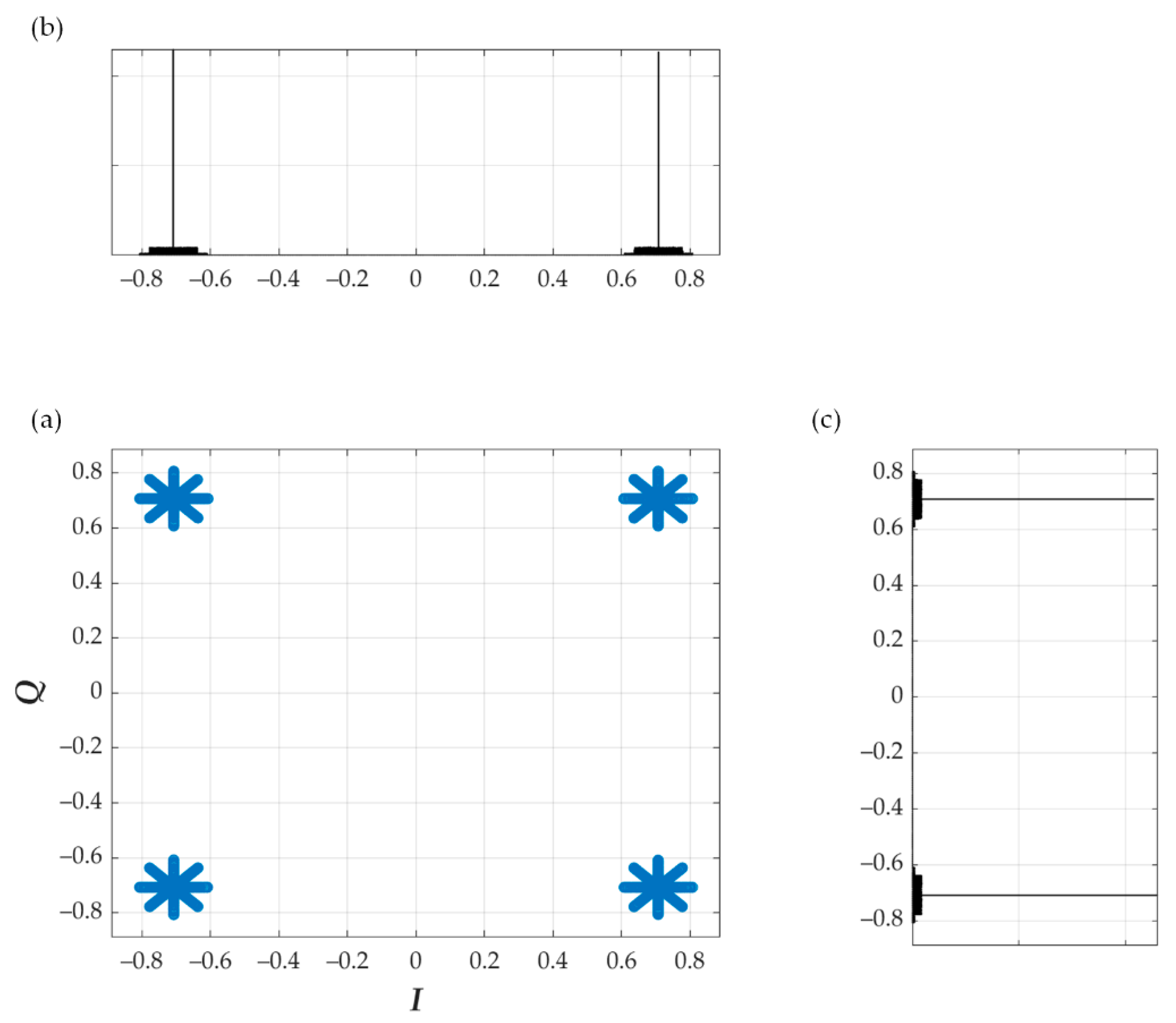
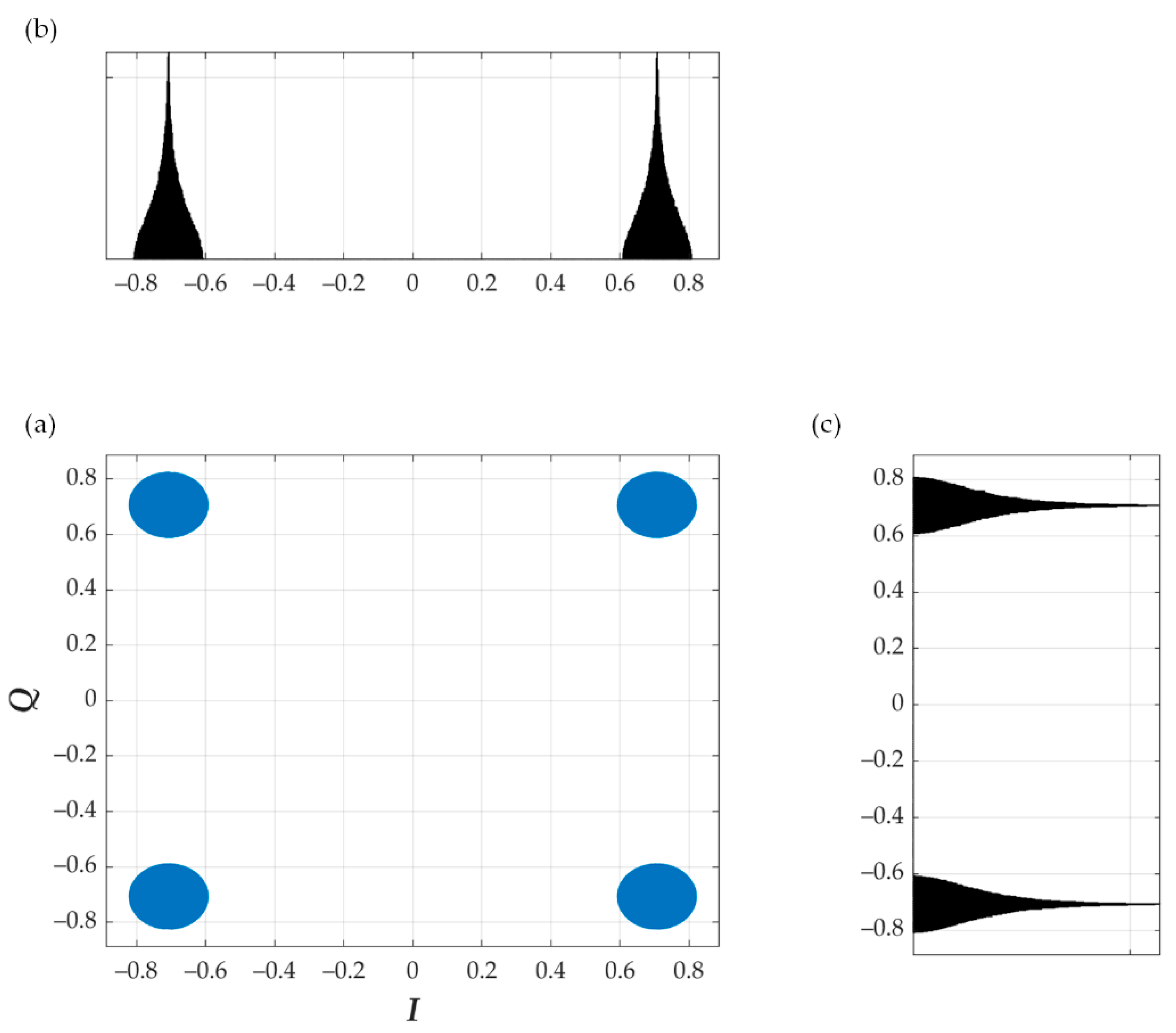
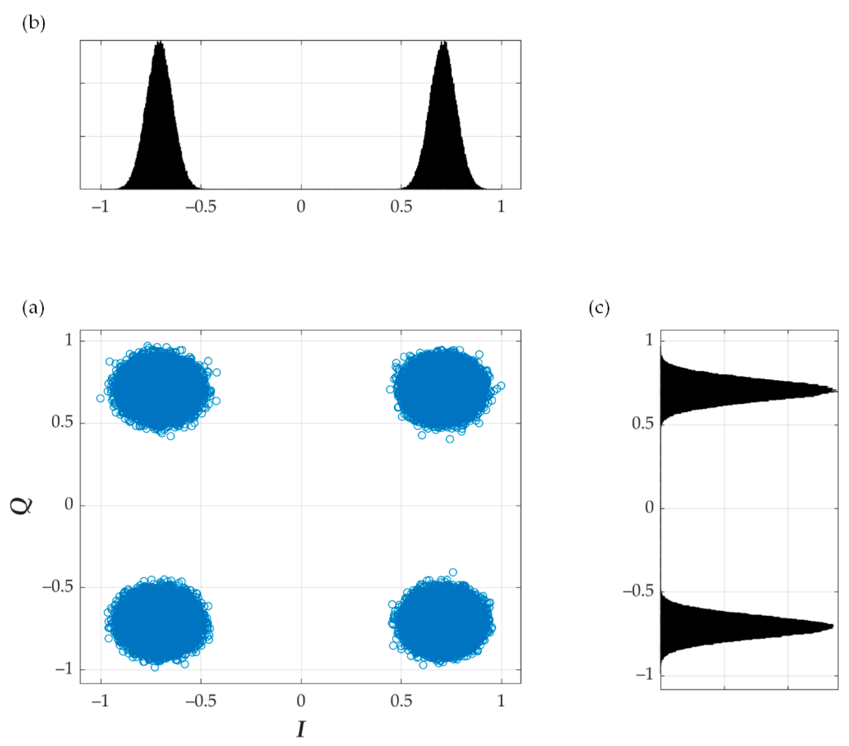
In steganographic signals, the lower EVM provides a lower probability of detecting the covert channel. On the other hand, the lack of fixed constellation points makes the histograms more random. Therefore, it is worth carrying out statistical analysis based on histograms and illustrating the covert channel implementation. In this simple example, we assumed that the cover is the 4 QAM signal, for i.e., takes four values according to Equation (3). Figure 7, Figure 8, Figure 9, Figure 10 and Figure 11 show the impact of random and on the obtained constellations and histograms.
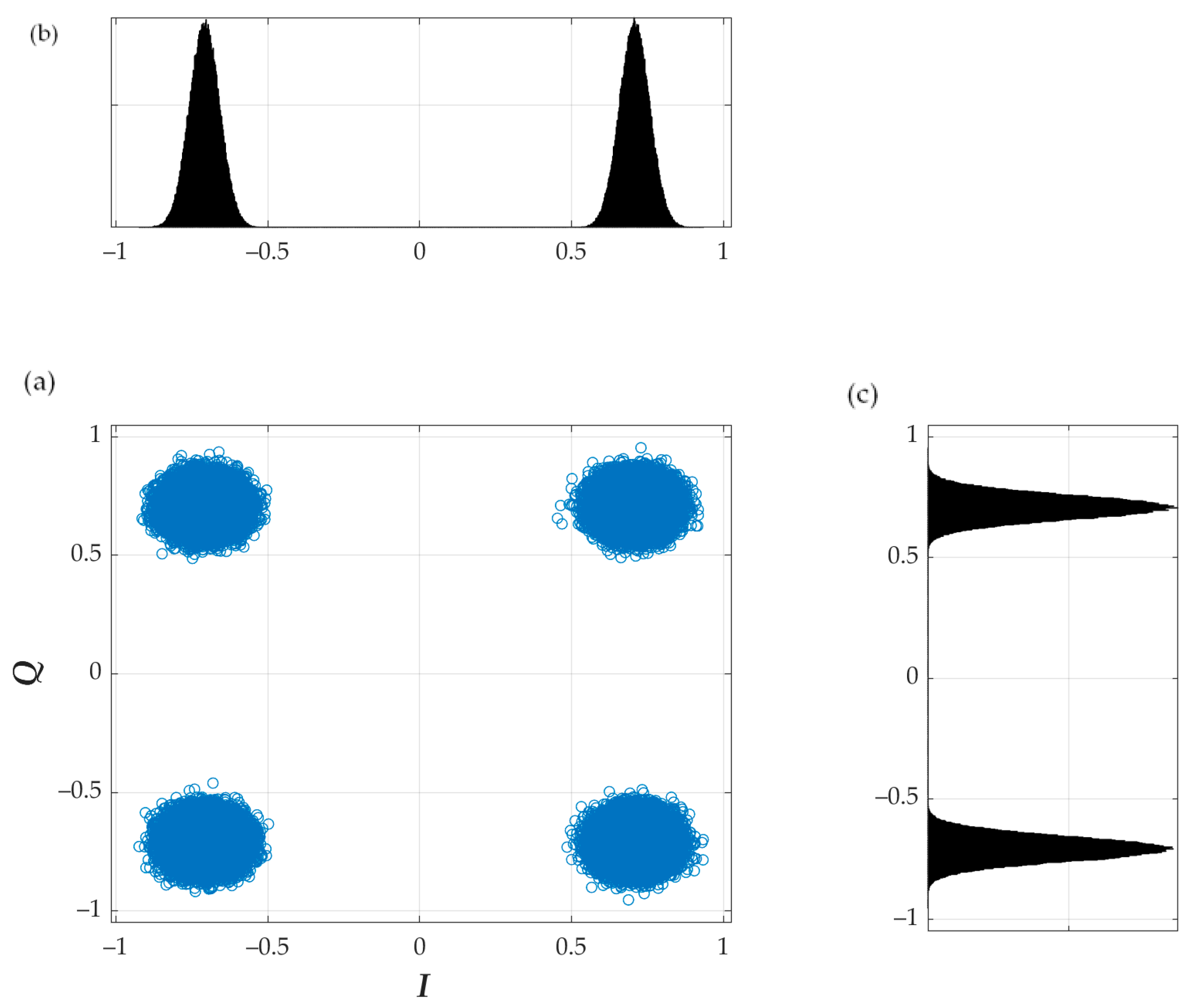
In Figure 7, Figure 8 and Figure 9, channel interference impact was not considered. On the other hand, we assumed that the transmitter system did not introduce any impairments, i.e., transmitter EVM is equal to 0%. In real conditions, i.e., EVM > 0, masking the steganographic information is increasing. So, we can see that thanks to the random parameters and the distributions of the constellation points in the planes of the IQ quadrature components converge to the Gaussian distributions. Additionally, a real radio channel masks the presence of a covert channel, which is well illustrated by Figure 10 and Figure 11. In these cases, we assume that the energy per bit to noise power spectral density ratio, for the signal cover is equal to 20 dB. It is worth emphasizing that the initial phase has no influence on the resulting bit rate of the covert channel and the obtained BER, but it has a masking function.
5. Simulation Analysis of Dirty Constellations
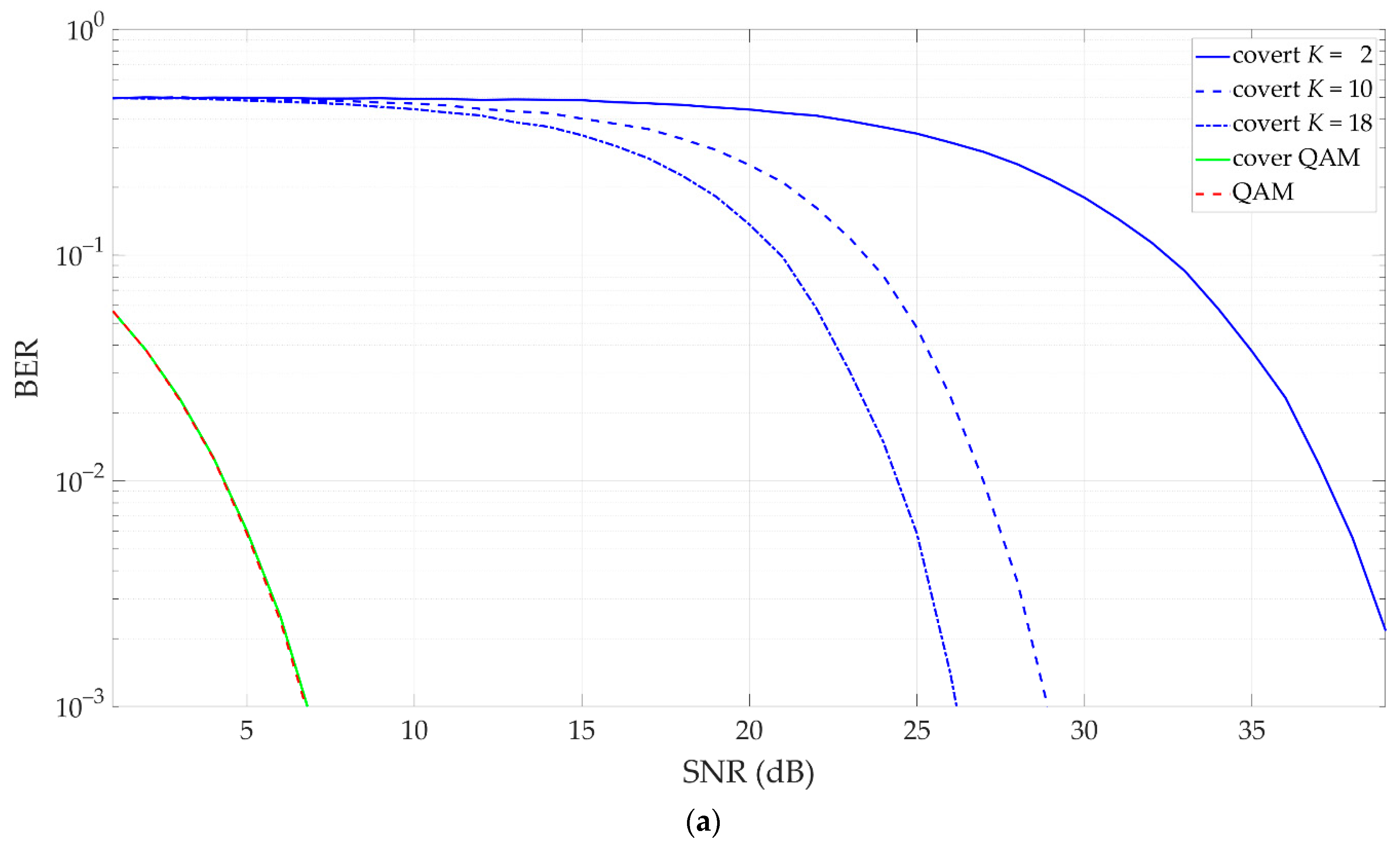
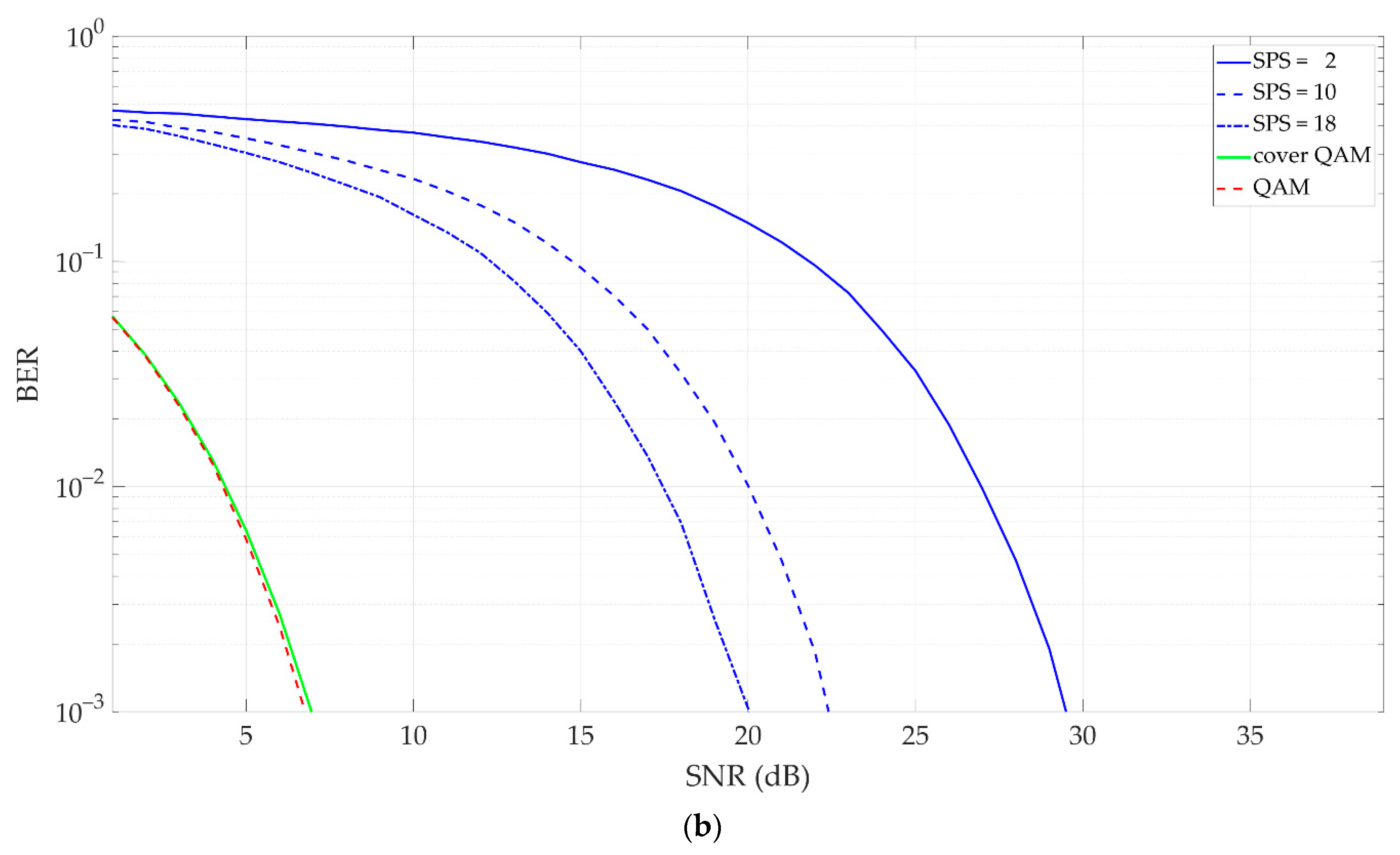
Based on simulation studies, we compared our solution with the dirty constellation method presented in [30]. In this case, we assumed that the number of averaging in the DCM modulator corresponds to the number of covert symbols per carrier symbol (SPS) in [30], the cover is the 4 QAM signal, and . For easier comparison, we additionally assumed that the centroid distance and the radius of covert information dispersion in [30] remain constant. Figure 12 depicts the obtained comparison results of the transmission capabilities of the covert channels and the effect of the covert channels on the carrier QAM signals for EVM = 3%.
The transmission rate obtained for the covert channel is directly related to the number of symbols transmitted by the cover. Assuming the same value of the cover and steganographic information, K-fold averaging or given SPS brings about a K-fold reduction in the number of symbols transmitted over the covert channel. EVM at the level of 3% does not cause any noticeable deterioration of cover properties. In the proposed solution, compared to [30] higher numbers of averages need to be used to obtain similar BER levels for a covert channel.
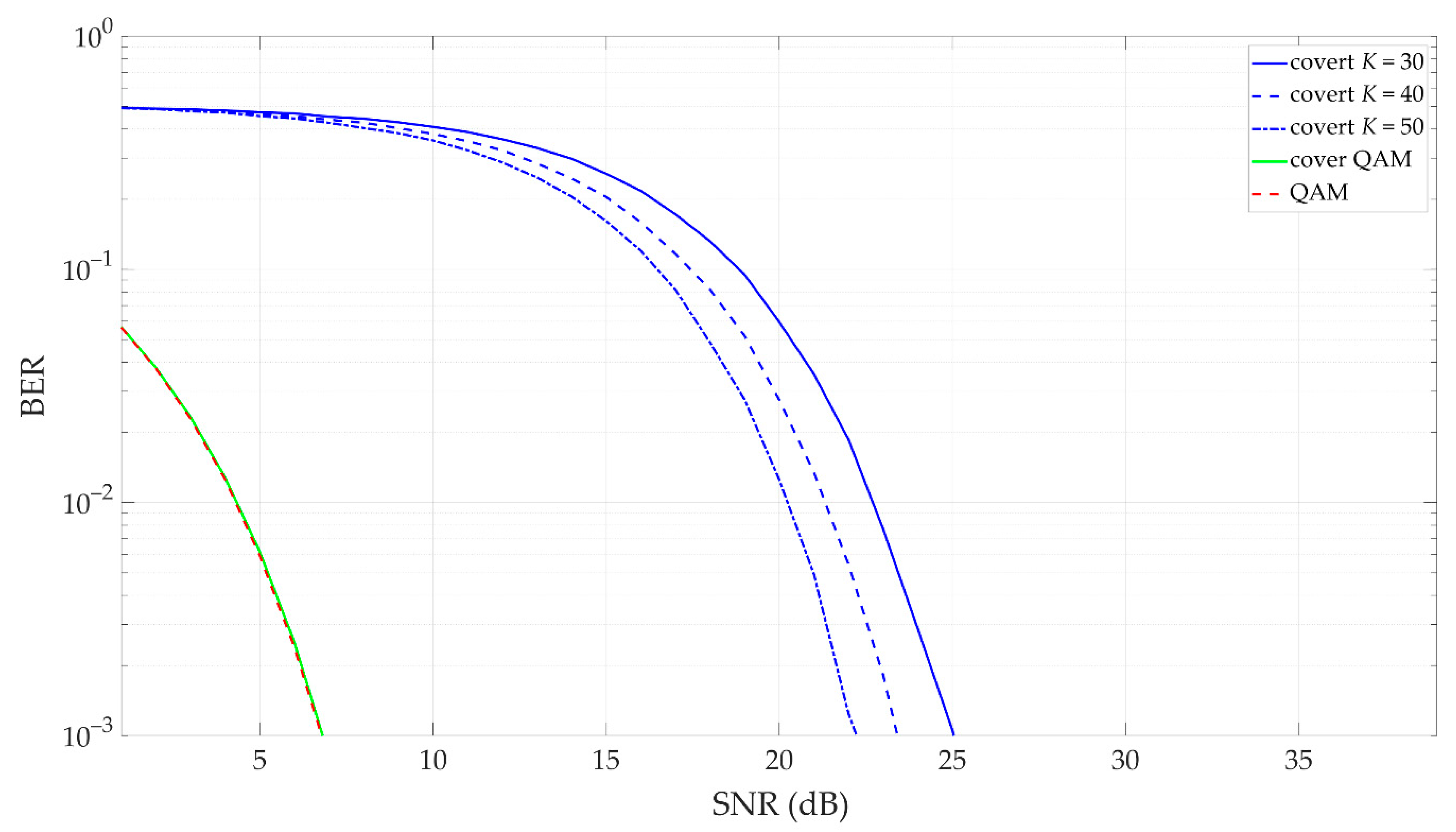
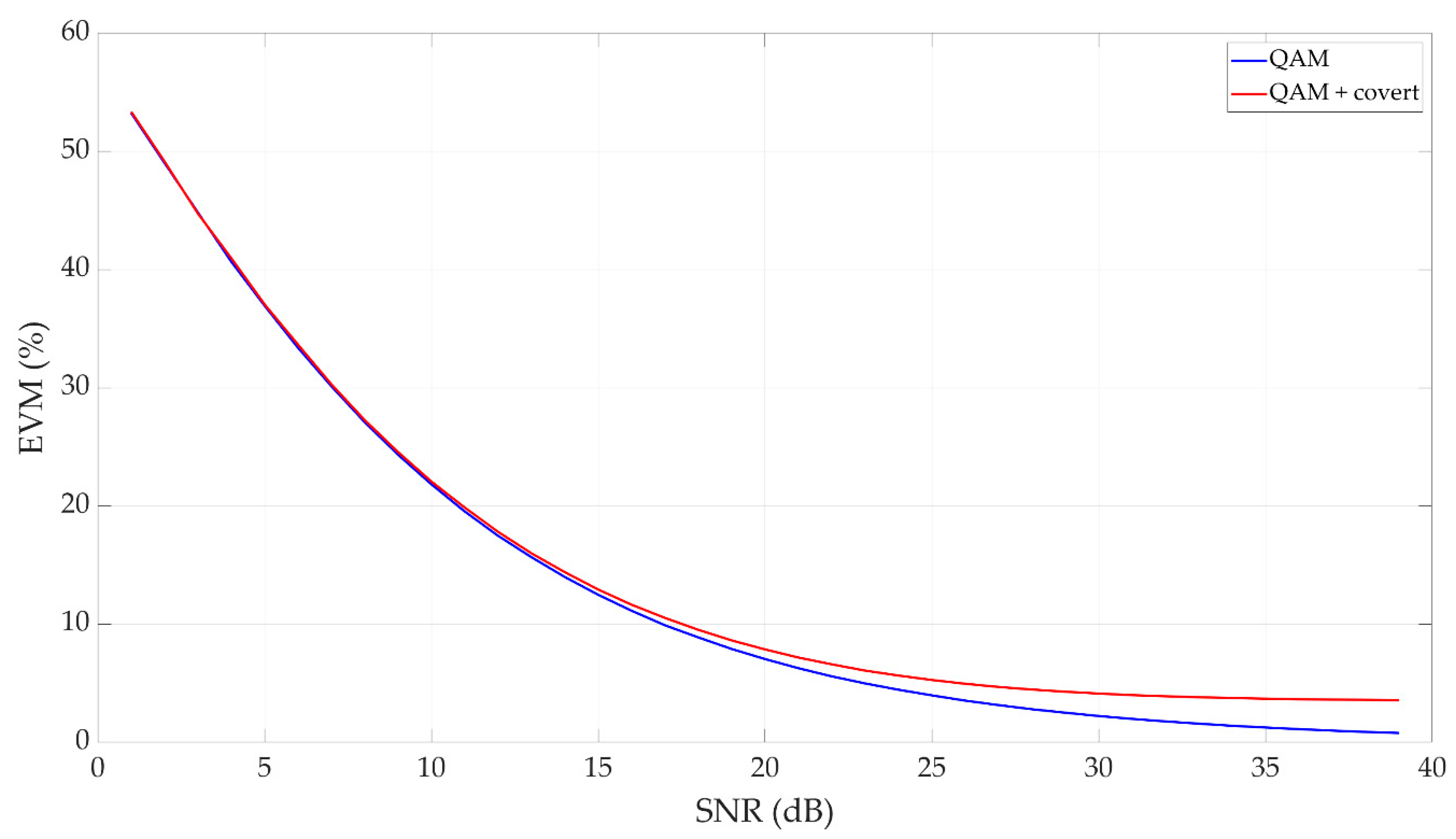
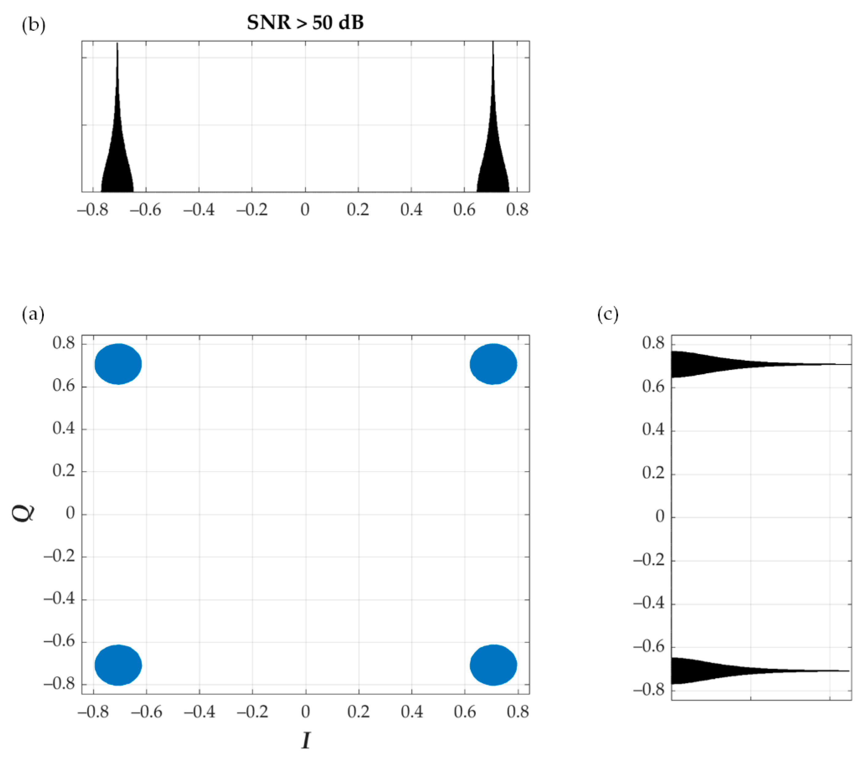
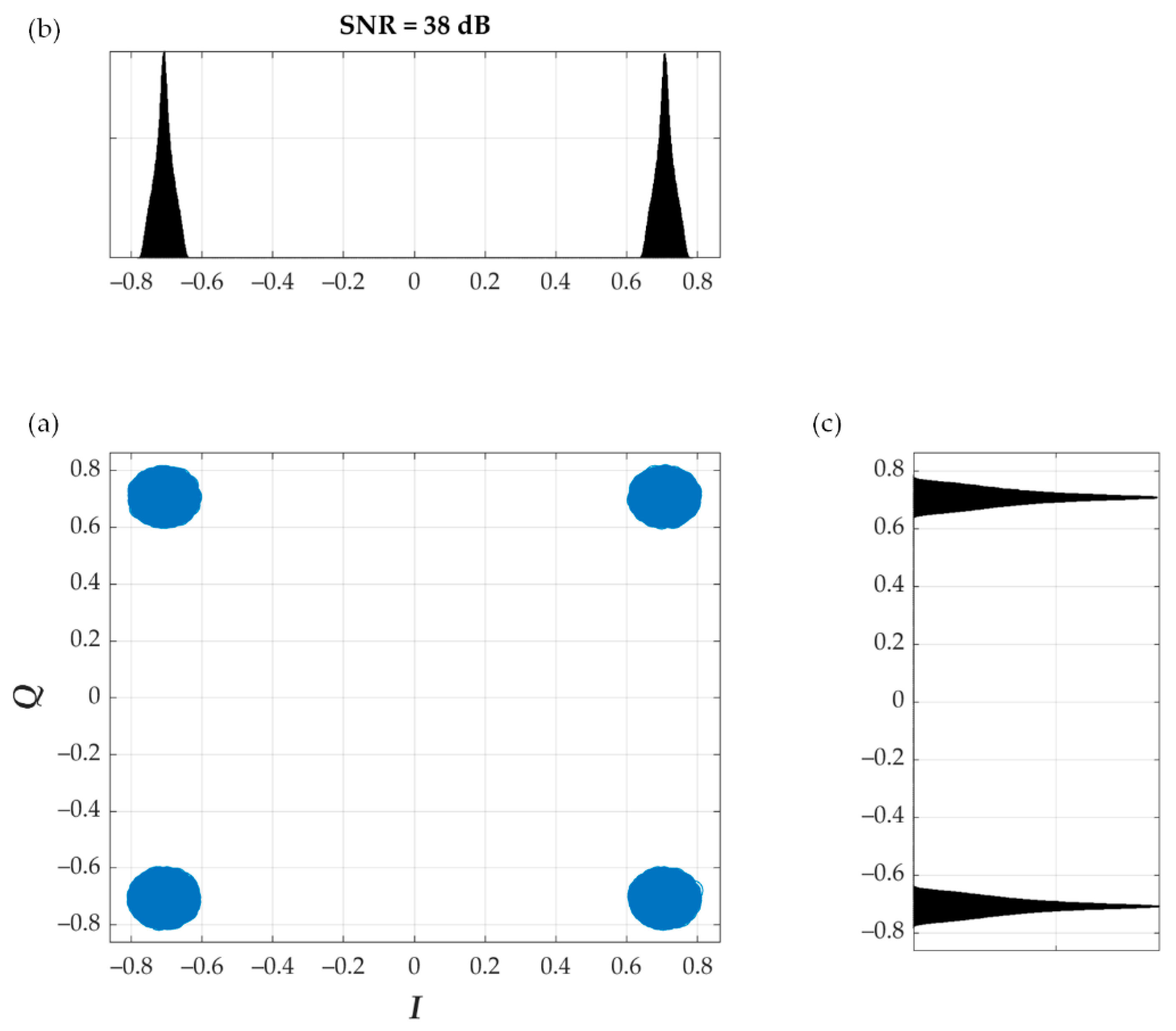
Introducing random reduces the level of energy per symbol of transmitted covert information, which means that it is necessary to increase the number of averages to provide the assumed BER level. An example for such a case (i.e., random ) was presented in Figure 13, Figure 14, Figure 15 and Figure 16. The cover is provided by 4 QAM, and . In Figure 13, we show BER versus SNR for different K and EVM = 3%. Figure 14 illustrates EVM versus SNR for the carrier signal and covert channel (), whereas Figure 15 and Figure 16 depict the constellations and histograms for EVM = 3%, SNR > 50 dB and SNR = 38 dB, respectively.
The simulation studies carried out showed that the increase in the number of averages ensures the BER reduction for a given SNR. On the other hand, introducing the covert information using the proposed approach did not significantly increase the EVM. The difference of a few percent is visible only for SNR > 20 dB. However, in this case, EVM < 8%. The obtained constellations and histograms show that for good transmission quality (i.e., SNR = 38 dB and SNR > 50 dB), the randomness of the centroid distance ensures the undetectability of the proposed method using statistical steganalysis.
6. Hardware Implementation
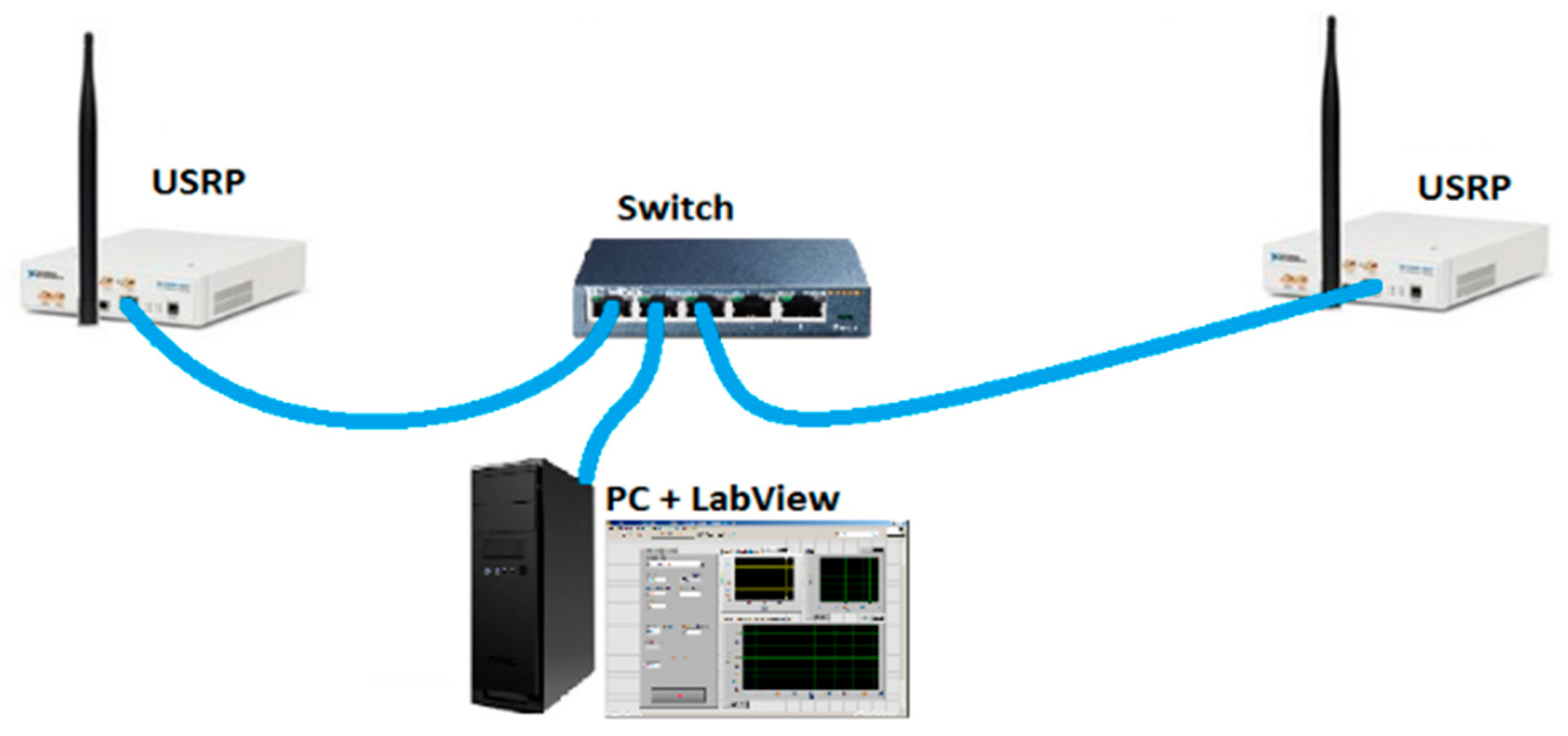
The concept of the phase drift-based dirty constellation was implemented by using the Universal Software Radio Peripheral (USRP) hardware platform manufactured by National Instruments (NI, Austin, TX, USA). In this case, we used the USRP-2920 model. USRP was the essential hardware part for generating a radio signal, while the software part was provided by the LabView software with MATLAB scripts installed on a personal computer (PC). An Ethernet network adapter with a bit rate of 1 Gb/s was used to provide communication between the USRP platforms and PC via a switch. Two USRP-2920 were used to implement a test-bed for detectors in the transmitter–receiver system. The prepared test-bed was placed in an office room. The distance between the transmitter and receiver was 5 m. This configuration is illustrated in Figure 17. The parameters of the carrier signal and covert information are presented in Table 2.
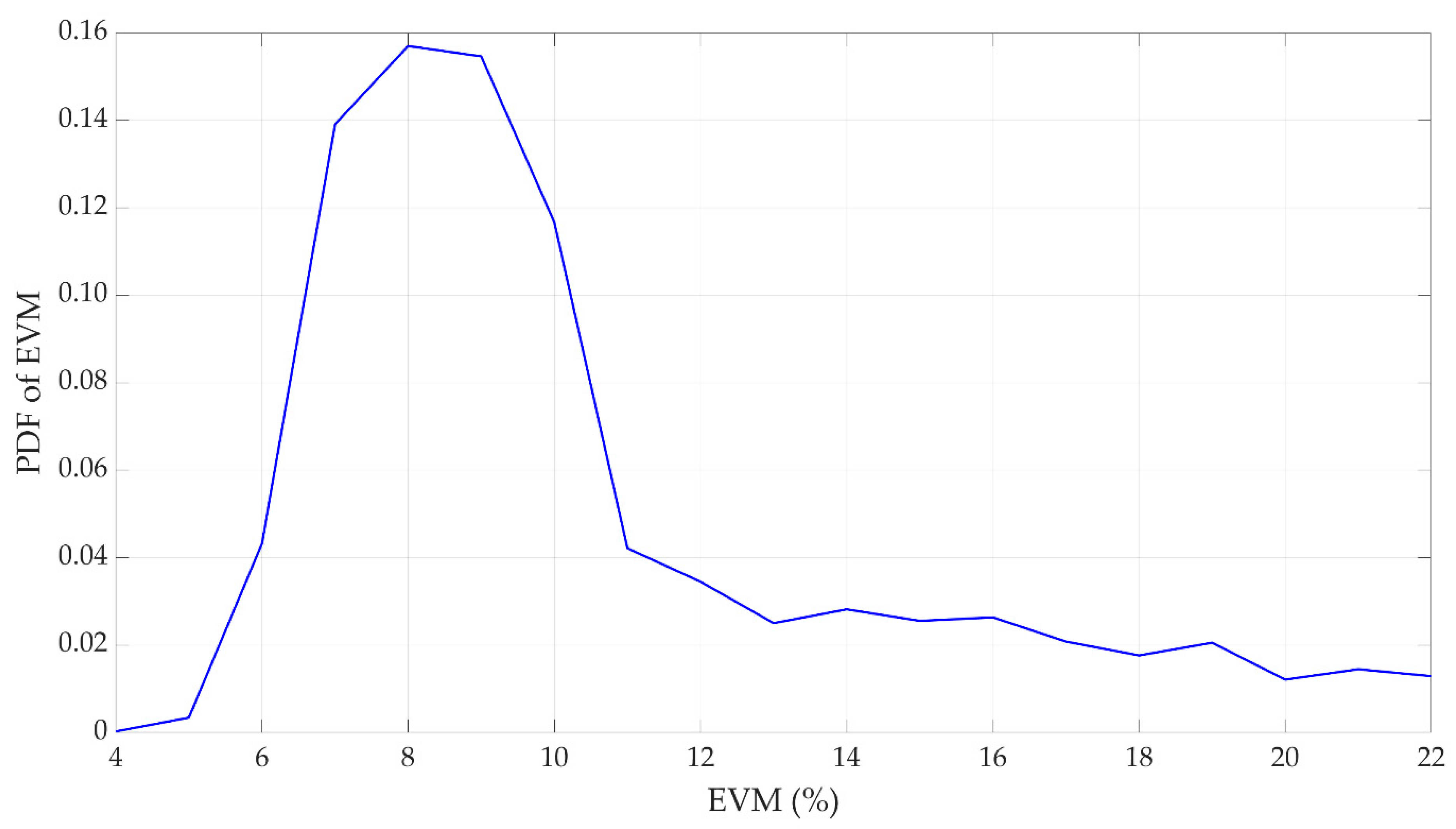
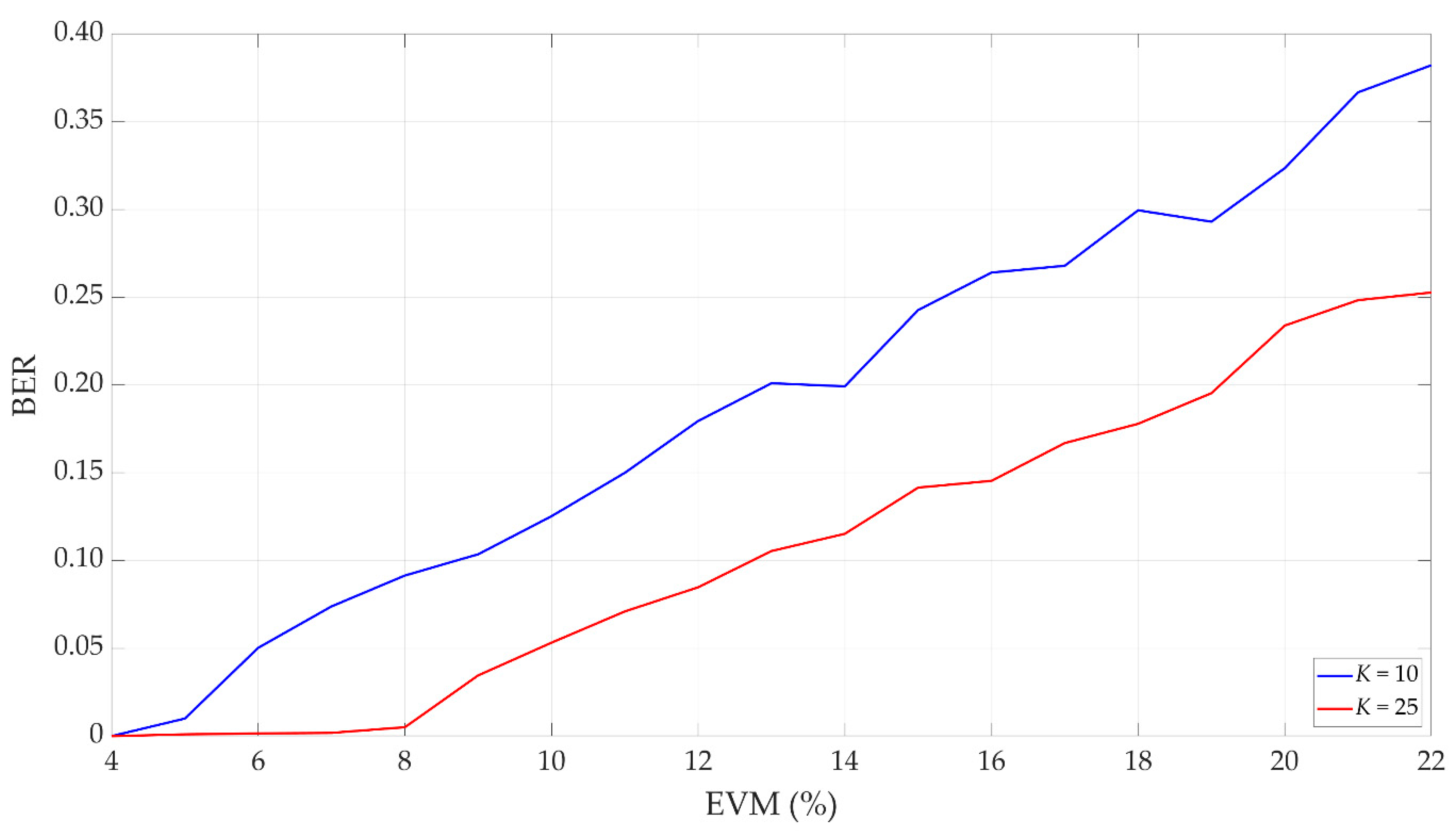
The results of the experimental research are presented in Figure 18 and Figure 19. In this case, we determined a probability density function (PDF) of EVM and BER versus EVM graphs for two considered values (see Figure 18). The distribution of the EVM was estimated by using a normalized histogram (see Figure 19).
The carrier constellation is subject to distortions caused by propagation phenomena and impairments introduced by the transceiver systems. We may see that the covert signal detectability reduces if the carrier distortion (i.e., EVM) increases. Tests were performed for two average values: and . As expected, increasing the number of averages provides the increase in the covert signal detectability. On the other hand, the transmission rate decreases.
Based on the PDF of EVM, we can conclude that for the analyzed 4 QAM and the average EVM oscillates between 8–12%. Comparing this value with Table 1, we can expect good transmission quality. On the other hand, increasing the distance between the transmitter and receiver will degrade the transmission quality due to the influence of the propagation conditions occurring in the radio channel. Hence, the adaptive selection of the parameters of the developed method depending on the propagation conditions will determine its future usefulness.
7. Conclusions
In this paper, we presented the novel dirty modulation method based on the phase drift, which is intended to create covert channels in radio transmissions using the N-ary PSK or QAM modulations. The method is based on the DCM approach that was previously used to watermark audio signals. In the proposed solution, a random change of the dirty constellation parameters is possible. It ensures its greater resistance to detection. On the other hand, it is possible to adapt these parameters to the modulation type and propagation conditions in the current radio channel.
In the paper, we described the idea of dirty modulation and developed a solution. Next, we introduced the criteria of the covert channel evaluation. Based on BER and EVM, we analyzed the proposed method using simulation studies and practical implementation, including comparison with other solutions. The obtained results showed that our dirty modulation method could be a valuable supplement to the existing steganographic methods.
In the near future, we want to focus on developing an adaptive method of selecting dirty modulation parameters, including the centroid distance and phase drift step, as well as multiple repetitions, i.e., averaging of secret transmission subsymbols. This will increase the undetectability of the proposed method. We also consider the effectiveness of this method in the case of additional use of the OFDM signal. Additionally, practical implementation of the method in the wireless part of the SDN within the aforementioned SOFTANET project is planned. In the near future, we want to implement ML algorithms (e.g., [39,40,47]) to increase the detection correctness of secret transmissions. These algorithms can be also used for time-variant selection of the developed dirty constellation parameters to improve their undetectability via various steganalysis techniques.
Author Contributions
Conceptualization, Z.P. and J.M.K.; methodology, K.G., Z.P. and J.M.K.; software, K.G.; validation, K.G.; formal analysis, K.G., Z.P. and J.M.K.; investigation, K.G.; resources, Z.P.; data curation, K.G. and Z.P.; writing—original draft preparation, K.G., Z.P. and J.M.K.; writing—review and editing, K.G. and J.M.K.; visualization, K.G.; supervision, Z.P. and J.M.K.; project administration, Z.P.; funding acquisition, Z.P. All authors have read and agreed to the published version of the manuscript.
Funding
This research was funded by the National Centre for Research and Development, grant number CYBERSECIDENT/381319/II/NCBR/2018 on “The federal cyberspace threat detection and response system” (acronym DET-RES) as part of the second competition of the CyberSecIdent Research and Development Program—Cybersecurity and e-Identity.
Data Availability Statement
The data presented in this study are available on request from the corresponding author. The data are not publicly available due to project restrictions.
Acknowledgments
The authors would like to express their great appreciation to the Electronics journal editors and anonymous reviewers for their valuable suggestions, which have improved the manuscript quality.
Conflicts of Interest
The authors declare no conflict of interest.
Abbreviations
| 5G | fifth generation |
| 6G | sixth generation |
| AI | artificial intelligence |
| BER | bit error rate |
| CSI | channel state information |
| DCM | drift correction modulation |
| DNS | Domain Name System |
| DSSS | direct sequence spread spectrum |
| EDA | European Defense Agency |
| EVM | error vector magnitude |
| FHSS | frequency-hopping spread spectrum |
| FSK | frequency-shift keying |
| HTTP | Hypertext Transfer Protocol |
| IEEE | Institute of Electrical and Electronics Engineers |
| IP | Internet Protocol |
| LPD | low probability of detection |
| LPI | low probability of intercept |
| MAC | medium access control |
| MIMO | multiple-input multiple-output |
| ML | machine learning |
| Ob | observer |
| OFDM | orthogonal frequency-division multiplexing |
| PC | personal computer |
| probability density function | |
| PDSCH | physical downlink shared channel |
| PN-ASK | pseudo-noise asymmetric shift keying |
| PSK | phase-shift keying |
| QAM | quadrature amplitude modulation |
| QPSK | quadrature phase-shift keying |
| SDN | software-defined network |
| SNR | signal-to-noise ratio |
| SPS | covert symbols per carrier symbol |
| SR | steganographic receiver |
| SS | steganographic source |
| TCP | Transmission Control Protocol |
| USRP | Universal Software Radio Peripheral |
References
- Zielińska, E.; Mazurczyk, W.; Szczypiorski, K. Trends in steganography. Commun. ACM 2014, 57, 86–95. [Google Scholar] [CrossRef]
- Duan, X.; Gou, M.; Liu, N.; Wang, W.; Qin, C. High-Capacity Image Steganography Based on Improved Xception. Sensors 2020, 20, 7253. [Google Scholar] [CrossRef]
- Järpe, E.; Weckstén, M. Velody 2—Resilient High-Capacity MIDI Steganography for Organ and Harpsichord Music. Appl. Sci. 2021, 11, 39. [Google Scholar] [CrossRef]
- Cao, M.; Tian, L.; Li, C. A Secure Video Steganography Based on the Intra-Prediction Mode (IPM) for H264. Sensors 2020, 20, 5242. [Google Scholar] [CrossRef] [PubMed]
- Lampson, B.W. A note on the confinement problem. Commun. ACM 1973, 16, 613–615. [Google Scholar] [CrossRef]
- Gianvecchio, S.; Wang, H.; Wijesekera, D.; Jajodia, S. Model-based covert timing channels: Automated modeling and evasion. In Proceedings of the Recent Advances in Intrusion Detection; Lippmann, R., Kirda, E., Trachtenberg, A., Eds.; Springer: Cambridge, MA, USA, 2008; Volume RAID 2008, pp. 211–230. [Google Scholar]
- Kothari, K.; Wright, M. Mimic: An active covert channel that evades regularity-based detection. Comput. Netw. 2013, 57, 647–657. [Google Scholar] [CrossRef] [Green Version]
- Walls, R.J.; Kothari, K.; Wright, M. Liquid: A detection-resistant covert timing channel based on IPD shaping. Comput. Netw. 2011, 55, 1217–1228. [Google Scholar] [CrossRef] [Green Version]
- Liu, G.; Zhai, J.; Dai, Y. Network covert timing channel with distribution matching. Telecommun. Syst. 2012, 49, 199–205. [Google Scholar] [CrossRef]
- Li, Y.; Zhang, X.; Xu, X.; Tan, Y. A Robust Packet-Dropout Covert Channel over Wireless Networks. IEEE Wirel. Commun. 2020, 27, 60–65. [Google Scholar] [CrossRef]
- Mileva, A.; Panajotov, B. Covert channels in TCP/IP protocol stack—Extended version. Cent. Eur. J. Comput. Sci. 2014, 4, 45–66. [Google Scholar] [CrossRef] [Green Version]
- Frikha, L.; Trabelsi, Z.; El-Hajj, W. Implementation of a covert channel in the 802.11 header. In Proceedings of the 2008 6th International Wireless Communications and Mobile Computing Conference (IWCMC), Crete Island, Greece, 6–8 August 2008; pp. 594–599. [Google Scholar]
- Szczypiorski, K.; Mazurczyk, W. Steganography in IEEE 802.11 OFDM symbols. Secur. Commun. Netw. 2011, 9, 118–129. [Google Scholar] [CrossRef]
- Shaukat, K.; Iqbal, F.; Hameed, I.A.; Hassan, M.U.; Luo, S.; Hassan, R.; Younas, A.; Ali, S.; Adeem, G.; Rubab, A.; et al. MAC protocols 802.11: A comparative study of throughput analysis and improved LEACH. In Proceedings of the 2020 17th International Conference on Electrical Engineering/Electronics, Computer, Telecommunications and Information Technology (ECTI-CON), Phuket, Thailand, 24–27 June 2020; pp. 421–426. [Google Scholar]
- Hassan, M.U.; Shahzaib, M.; Shaukat, K.; Hussain, S.N.; Mubashir, M.; Karim, S.; Shabir, M.A. DEAR-2: An energy-aware routing protocol with guaranteed delivery in wireless ad-hoc networks. In Recent Trends and Advances in Wireless and IoT-Enabled Networks; Jan, M.A., Khan, F., Alam, M., Eds.; EAI/Springer Innovations in Communication and Computing; Springer International Publishing: Cham, Germany, 2019; pp. 215–224. ISBN 978-3-319-99966-1. [Google Scholar]
- Frączek, W.; Szczypiorski, K. Perfect undetectability of network steganography. Secur. Commun. Netw. 2016, 9, 2998–3010. [Google Scholar] [CrossRef] [Green Version]
- Graniszewski, W.; Krupski, J.; Szczypiorski, K. The covert channel over HTTP protocol. In Proceedings of the Photonics Applications in Astronomy, Communications, Industry, and High-Energy Physics Experiments 2016, Wilga, Poland, 29 May–6 June 2016; SPIE: Washington, DC, USA, 2016; Volume 10031, p. 100314Z. [Google Scholar]
- Szczypiorski, K.; Drzymała, M.; Urbański, M.Ł. Network Steganography in the DNS Protocol. Int. J. Electron. Telecommun. 2016, 62, 343–346. [Google Scholar] [CrossRef]
- Smolarczyk, M.; Szczypiorski, K.; Pawluk, J. Multilayer Detection of Network Steganography. Electronics 2020, 9, 2128. [Google Scholar] [CrossRef]
- Chen, O.; Meadows, C.; Trivedi, G. Stealthy protocols: Metrics and open problems. In Concurrency, Security, and Puzzles; Lecture Notes in Computer Science; Springer: Cham, Germany, 2017; pp. 1–17. ISBN 978-3-319-51045-3. [Google Scholar]
- Bordel Sánchez, B.; Alcarria, R.; Robles, T.; Jara, A. Protecting Physical Communications in 5G C-RAN Architectures through Resonant Mechanisms in Optical Media. Sensors 2020, 20, 4104. [Google Scholar] [CrossRef] [PubMed]
- Yen, C.-T.; Huang, J.-F.; Zhang, W.-Z. Hiding Stealth Optical CDMA Signals in Public BPSK Channels for Optical Wireless Communication. Appl. Sci. 2018, 8, 1731. [Google Scholar] [CrossRef] [Green Version]
- Moskowitz, I.S.; Safier, P.N.; Cotae, P. Pre-Nodulation Physical Layer Steganography 2013. U.S. Patent Application 13/573,671, 25 April 2013. [Google Scholar]
- Szczepaniak, E.; Piotrowski, Z. Radio transmission masking on the example of FSK modulation. In Proceedings of the 2017 21st International Conference on Signal Processing Algorithms, Architectures, Arrangements, and Applications (SPA), Poznan, Poland, 20–22 September 2017; pp. 394–399. [Google Scholar]
- Hijaz, Z.; Frost, V.S. Exploiting OFDM systems for covert communication. In Proceedings of the 2010 Military Communications Conference (MILCOM), San Jose, CA, USA, 31 October–3 November 2010; pp. 2149–2155. [Google Scholar]
- Classen, J.; Schulz, M.; Hollick, M. Practical covert channels for WiFi systems. In Proceedings of the 2015 IEEE Conference on Communications and Network Security (CNS), Florence, Italy, 28–30 September 2015; pp. 209–217. [Google Scholar]
- Bash, B.A.; Goeckel, D.; Towsley, D.; Guha, S. Hiding information in noise: Fundamental limits of covert wireless communication. IEEE Commun. Mag. 2015, 53, 26–31. [Google Scholar] [CrossRef] [Green Version]
- Hero, A.O. Secure space-time communication. IEEE Trans. Inf. Theory 2003, 49, 3235–3249. [Google Scholar] [CrossRef]
- Cao, P.; Liu, W.; Liu, G.; Zhai, J.; Ji, X.; Dai, Y. A novel wireless covert channel for MIMO system. In Proceedings of the 2020 6th International Conference on Artificial Intelligence and Security (ICAIS), Hohhot, China, 17–20 July 2020; Sun, X., Wang, J., Bertino, E., Eds.; Springer: Berlin/Heidelberg, Germany, 2020; Volume 3, pp. 351–362. [Google Scholar]
- Dutta, A.; Saha, D.; Grunwald, D.; Sicker, D. Secret agent radio: Covert communication through dirty constellations. In Proceedings of the Information Hiding, Berkeley, CA, USA, 15–18 May 2012; Kirchner, M., Ghosal, D., Eds.; Springer: Berlin/Heidelberg, Germany, 2012; Volume IH 2012, pp. 160–175. [Google Scholar]
- Cao, P.; Liu, W.; Liu, G.; Ji, X.; Zhai, J.; Dai, Y. A Wireless Covert Channel Based on Constellation Shaping Modulation. Secur. Commun. Netw. 2018, 2018, 1–15. [Google Scholar] [CrossRef] [Green Version]
- D’Oro, S.; Restuccia, F.; Melodia, T. Hiding data in plain sight: Undetectable wireless communications through pseudo-noise asymmetric shift keying. In Proceedings of the 2019 38th IEEE Conference on Computer Communications (INFOCOM), Paris, France, 29 April–2 May 2019; IEEE: New York, NY, USA; pp. 1585–1593. [Google Scholar]
- Piotrowski, Z. Drift Correction Modulation scheme for digital signal processing. Math. Comput. Model. 2013, 57, 2660–2670. [Google Scholar] [CrossRef]
- Lyons, R.G. Understanding Digital Signal Processing, 3rd ed.; Prentice Hall: Upper Saddle River, NJ, USA, 2010; ISBN 978-0-13-702741-5. [Google Scholar]
- Zaidi, Z.; Friderikos, V.; Yousaf, Z.; Fletcher, S.; Dohler, M.; Aghvami, H. Will SDN Be Part of 5G? IEEE Commun. Surv. Tutor. 2018, 20, 3220–3258. [Google Scholar] [CrossRef] [Green Version]
- Leonardi, L.; Lo Bello, L.; Aglianò, S. Priority-based bandwidth management in virtualized software-defined networks. Electronics 2020, 9, 1009. [Google Scholar] [CrossRef]
- Semong, T.; Maupong, T.; Anokye, S.; Kehulakae, K.; Dimakatso, S.; Boipelo, G.; Sarefo, S. Intelligent Load Balancing Techniques in Software Defined Networks: A Survey. Electronics 2020, 9, 1091. [Google Scholar] [CrossRef]
- Alhaddad, M.J.; Alkinani, M.H.; Atoum, M.S.; Alarood, A.A. Evolutionary Detection Accuracy of Secret Data in Audio Steganography for Securing 5G-Enabled Internet of Things. Symmetry 2020, 12, 2071. [Google Scholar] [CrossRef]
- Shaukat, K.; Luo, S.; Varadharajan, V.; Hameed, I.A.; Xu, M. A Survey on Machine Learning Techniques for Cyber Security in the Last Decade. IEEE Access 2020, 8, 222310–222354. [Google Scholar] [CrossRef]
- Shaukat, K.; Luo, S.; Varadharajan, V.; Hameed, I.A.; Chen, S.; Liu, D.; Li, J. Performance Comparison and Current Challenges of Using Machine Learning Techniques in Cybersecurity. Energies 2020, 13, 2509. [Google Scholar] [CrossRef]
- Roetteler, M.; Svore, K.M. Quantum Computing: Codebreaking and Beyond. IEEE Secur. Priv. 2018, 16, 22–36. [Google Scholar] [CrossRef]
- Zhang, H.; Ji, Z.; Wang, H.; Wu, W. Survey on quantum information security. China Commun. 2019, 16, 1–36. [Google Scholar] [CrossRef]
- Chaumont, M. Deep learning in steganography and steganalysis. In Digital Media Steganography; Hassaballah, M., Ed.; Academic Press: Cambridge, MA, USA, 2020; pp. 321–349. ISBN 978-0-12-819438-6. [Google Scholar]
- Li, F.; Tang, H.; Zou, Y.; Huang, Y.; Feng, Y.; Peng, L. Research on information security in text emotional steganography based on machine learning. Enterp. Inf. Syst. 2020, 1–18. [Google Scholar] [CrossRef]
- Sutherland, C.; Brun, T.A. Quantum steganography over noiseless channels: Achievability and bounds. Phys. Rev. A 2020, 101, 052319. [Google Scholar] [CrossRef]
- Chaharlang, J.; Mosleh, M.; Rasouli-Heikalabad, S. A novel quantum steganography-Steganalysis system for audio signals. Multimed. Tools Appl. 2020, 79, 17551–17577. [Google Scholar] [CrossRef]
- Alam, T.M.; Shaukat, K.; Hameed, I.A.; Luo, S.; Sarwar, M.U.; Shabbir, S.; Li, J.; Khushi, M. An Investigation of Credit Card Default Prediction in the Imbalanced Datasets. IEEE Access 2020, 8, 201173–201198. [Google Scholar] [CrossRef]
- ETSI. NR; Base Station (BS) Radio Transmission and Reception (3GPP TS 38.104 Version 15.5.0 Release 15); European Telecommunications Standards Institute (ETSI), 3rd Generation Partnership Project (3GPP): Sophia-Antipolis, France, 2019. [Google Scholar]
- Simmons, G.J. The prisoners’ problem and the subliminal channel. In Proceedings of the Advances in Cryptology, Santa Barbara, CA, USA, 22–24 August 1983; Chaum, D., Ed.; Springer: Berlin/Heidelberg, Germany, 1984; pp. 51–67. [Google Scholar]
- Szczypiorski, K.; Janicki, A.; Wendzel, S.; Wendzel, S. “The Good, the Bad and The Ugly”: Evaluation of Wi-Fi steganography. J. Commun. 2015, 10, 747–752. [Google Scholar] [CrossRef] [Green Version]
Figure 1.
Dirty constellation: (a) assigning bits to constellation points; (b) chosen constellation point.
Figure 1.
Dirty constellation: (a) assigning bits to constellation points; (b) chosen constellation point.

Figure 2.
Example of constellation with drift phase: (a) vector yk for K = 3; (b) quadrature amplitude modulation (QAM) cover (transmitted overt sequence of symbols: 1 + j, 1 − j, 1 − j) and resultant constellation with drift phase applied for preset vector yk.
Figure 2.
Example of constellation with drift phase: (a) vector yk for K = 3; (b) quadrature amplitude modulation (QAM) cover (transmitted overt sequence of symbols: 1 + j, 1 − j, 1 − j) and resultant constellation with drift phase applied for preset vector yk.

Figure 3.
Additional yk and carrier xn constellation points.

Figure 4.
Constellations of carrier and the covert channels applied with: (a) fixed initial phase φx; (b) random φx; and (c) random φx and Am.
Figure 4.
Constellations of carrier and the covert channels applied with: (a) fixed initial phase φx; (b) random φx; and (c) random φx and Am.

Figure 5.
Receiver and transmitter (framework) of phase drift-based covert channel.

Figure 6.
Concept of mobile observer for assessing steganographic method.

Figure 7.
(a) Constellation (b) in-phase and (c) quadrature histograms for 4 quadrature amplitude modulation (QAM) cover and drift correction modulation (DCM) covert channel with M = 4 and for fixed parameters.
Figure 7.
(a) Constellation (b) in-phase and (c) quadrature histograms for 4 quadrature amplitude modulation (QAM) cover and drift correction modulation (DCM) covert channel with M = 4 and for fixed parameters.

Figure 8.
(a) Constellation (b) in-phase and (c) quadrature histograms for 4 QAM cover and DCM covert channel with M = 4 and for random Am.
Figure 8.
(a) Constellation (b) in-phase and (c) quadrature histograms for 4 QAM cover and DCM covert channel with M = 4 and for random Am.

Figure 9.
(a) Constellation (b) in-phase and (c) quadrature histograms for 4 QAM cover and DCM covert channel with M = 4 and for random Am and φx.
Figure 9.
(a) Constellation (b) in-phase and (c) quadrature histograms for 4 QAM cover and DCM covert channel with M = 4 and for random Am and φx.

Figure 10.
(a) Constellation, (b) in-phase and (c) quadrature histograms for 4 QAM cover and DCM covert channel with M = 4 and for random Am and φx, Eb/N0 = 20 dB for cover.
Figure 10.
(a) Constellation, (b) in-phase and (c) quadrature histograms for 4 QAM cover and DCM covert channel with M = 4 and for random Am and φx, Eb/N0 = 20 dB for cover.

Figure 11.
(a) Constellation, (b) in-phase and (c) quadrature histograms for 4 QAM cover and Eb/N0 = 20 dB, and without DCM covert channel.
Figure 11.
(a) Constellation, (b) in-phase and (c) quadrature histograms for 4 QAM cover and Eb/N0 = 20 dB, and without DCM covert channel.

Figure 12.
Comparison of dirty constellation methods based on bit error rate (BER) versus signal-to-noise ratio (SNR) graphs for EVM = 3%: (a) proposed solution; (b) solution presented in [30].
Figure 12.
Comparison of dirty constellation methods based on bit error rate (BER) versus signal-to-noise ratio (SNR) graphs for EVM = 3%: (a) proposed solution; (b) solution presented in [30].


Figure 13.
BER versus SNR for different K, random Am, and error vector magnitude (EVM) = 3%.

Figure 14.
Error vector magnitude (EVM) versus SNR for cover and covert channel (K = 30), and random Am.
Figure 14.
Error vector magnitude (EVM) versus SNR for cover and covert channel (K = 30), and random Am.

Figure 15.
(a) Constellation, (b) in-phase and (c) quadrature histogram for SNR > 50 dB, K = 30, random Am, and EVM = 3%.
Figure 15.
(a) Constellation, (b) in-phase and (c) quadrature histogram for SNR > 50 dB, K = 30, random Am, and EVM = 3%.

Figure 16.
(a) Constellation, (b) in-phase and (c) quadrature histogram for SNR = 38 dB, K = 30, random Am, and EVM = 3%.
Figure 16.
(a) Constellation, (b) in-phase and (c) quadrature histogram for SNR = 38 dB, K = 30, random Am, and EVM = 3%.

Figure 17.
Test-bed based on USRP-2920 used for practical verification.

Figure 18.
Covert signal detection results: probability density function (PDF) of EVM.

Figure 19.
Covert signal detection results: BER versus EVM for selected K.


Table 1.
Error vector magnitudes (EVMs) in 5G standard.
| Modulation Scheme for Physical Downlink Shared Channel (PDSCH) | Required EVM (%) |
|---|---|
| QPSK | 17.5 |
| 16 QAM | 12.5 |
| 64 QAM | 8.0 |
| 256 QAM | 3.5 |
Table 2.
Parameters of radio signal.
| Signal | Parameters | Value |
|---|---|---|
| Cover (carrier) | Modulation type | 4 QAM |
| Carrier frequency | 850 MHz | |
| Bandwidth | 1 MHz | |
| Transmission rate | 4 MHz | |
| Covert information | M | 4 |
| Am | 0.05·An | |
| φm | ±π/4, ±3π/4 | |
| K | 10 and 25 | |
| Transmission rate | 400 kb/s (for K = 10) | |
| 160 kb/s (for K = 25) |
Publisher’s Note: MDPI stays neutral with regard to jurisdictional claims in published maps and institutional affiliations. |
© 2021 by the authors. Licensee MDPI, Basel, Switzerland. This article is an open access article distributed under the terms and conditions of the Creative Commons Attribution (CC BY) license (http://creativecommons.org/licenses/by/4.0/).
Share and Cite
MDPI and ACS Style
Grzesiak, K.; Piotrowski, Z.; Kelner, J.M. A Wireless Covert Channel Based on Dirty Constellation with Phase Drift. Electronics 2021, 10, 647. https://doi.org/10.3390/electronics10060647
AMA Style
Grzesiak K, Piotrowski Z, Kelner JM. A Wireless Covert Channel Based on Dirty Constellation with Phase Drift. Electronics. 2021; 10(6):647. https://doi.org/10.3390/electronics10060647
Chicago/Turabian StyleGrzesiak, Krystian, Zbigniew Piotrowski, and Jan M. Kelner. 2021. "A Wireless Covert Channel Based on Dirty Constellation with Phase Drift" Electronics 10, no. 6: 647. https://doi.org/10.3390/electronics10060647
Note that from the first issue of 2016, this journal uses article numbers instead of page numbers. See further details here.