
Design Considerations and Selection of Cost-Effective Switched Reluctance Drive for Radiator Cooling Fans

Department of Mechatronics Engineering, Kyungsung University, Busan 48434, Korea
*
Author to whom correspondence should be addressed.
Electronics 2021, 10(8), 917; https://doi.org/10.3390/electronics10080917
Submission received: 22 March 2021
/
Revised: 5 April 2021
/
Accepted: 8 April 2021
/
Published: 12 April 2021
(This article belongs to the Special Issue Recent Issues on Motors and Motor Drives)
Abstract
:Switched reluctance motors (SRMs) are simple in structure, easy to manufacture, magnet-less, brushless, and highly robust compared to other AC motors which makes them a good option for applications that operate in harsh environment. However, the motor has non-linear magnetic characteristics, and it comes with various pole-phase combinations and circuit topologies that causes many difficulties in deciding on which type to choose. In this paper, the viability of SRM as a low-cost, rugged machine for vehicle radiator cooling fan is considered. First, necessary design considerations are presented, then three commonly use types of SRM are analyzed: A 3-phase 6/4, 3-phase 12/8, and a 4-phase 8/6 to find their static and dynamic characteristics so the most suitable type can be selected. Simulation results show that the 8/6 SRM produces the highest efficiency with less phase current which reduces the converter burden. However, with asymmetric half bridge converter, eight power switches are required for 8/6 SRM and thus put a burden on the overall drive cost. As a solution, the Miller converter with only six switches for four phase SRM. To verify the proposed idea, the 8/6 SRM was manufactured and tested. The results show that Miller converter can be used for the proposed SRM with slightly reduced efficiency at 80.4%.
1. Introduction
The cooling system is essential in all kinds of vehicle. Coolant is distributed around the engine to regulate its temperature. Radiator cooling fan plays the role of dissipating the heat of the coolant in the radiator before the cycle goes again. These days, in the era of vehicle electrification, cooling fans are powered with electric motors. Despite the advance systems, the low-cost DC motors are still commonly used in low-cost vehicles [1]. However, DC motors have commutator and brush. The contact between the two is the operating principle the motor, but it also creates some disadvantages such as carbon dust and high maintenance requirement. Moreover, even though structurally DC motors are simple, the mechanical connection between motor, commutator, and brush reduce the robustness and increases chance of spark during commutation.
This problem can be solved easily by implementing brushless DC (BLDC) motors [2,3]. BLDC motors have been reported to replace DC motors in a lot of applications. It has good control performance, high efficiency, and is relatively small-sized. However, BLDC motors use permanent magnets (PMs). Literatures have proven that rare-earth PMs improve power density and dynamic performance [4]. The problem with PMs, other than the availability concerns, is that there is a change of demagnetization in very high-temperature environment [5]. Moreover, the structure is less rugged, if compared to non-PM motors.
Switched reluctance motors (SRMs) are magnet-less and brush-less. The windings are wound in a concentrated manner only around the stator poles. The remaining structure is merely a stack of core laminations for stator and rotor. Generally, SRM is easy to manufacture so its production costs are comparatively low which becomes its main selling point [6]. Because of this simple construction, structurally it is rugged and required little-to-no maintenance. This is a good feature for radiator cooling fan. However, it possesses some drawbacks such as high torque ripple and acoustic noise which is inherent from its operating principle: Switching the phase on and off repeatedly [7,8].
Three conventional types of SRM are analyzed and compared in this paper. Two 3-phase, 6/4 and 12/8, and one 4-phase, 8/6 SRMs are designed with the same size and rated performance for fair comparison. The design parameters are set to satisfy the cooling fan requirements. The characteristics of each motor are observed with a finite element analysis (FEA) software and explained in a comparative manner to provide a better understanding in SRM and how to choose the appropriate type for a particular application.
Asymmetric half bridge (AHB) converter is mainly used to operate SRMs [9,10]. By using two power switches for each phase, it provides great control flexibility since each switch can be independently turned on and off. Furthermore, it is also reliable because if one switch breaks down, the motor can still run though with reduced performance. However, with the increasing number of phase, the total number of switches also increases which elevates the overall drive cost. To solve this problem, various converter topologies have been suggested over the years. Literature in [11,12] summed up some of them. In this paper, the Miller converter is used to reduce the number of switches in the 4-phase 8/6 SRM to that of a 3-phase SRM, which is from 8 to 6. Dynamic simulation was performed to compare the performance when using the regular AHB and Miller topology.
A prototype motor was manufactured according to the result of FEA simulation and tested to verify the performance. The experiment was performed by using both AHB and Miller and the results were compared. It is confirmed through simulations and experiments that SRM is a viable actuator for radiator cooling fans.
2. Design of Proposed SRM
2.1. Design Considerations
The selection of phase and pole numbers are important to design the proper motor for a given application. Despite the advantages, SRM is also known for the drawbacks such as high torque ripple and acoustic noise, which is why torque ripple is considered as one of the most important parameters in implementing the motor. Similar to other AC machines, more pole number equals lower torque ripple, but it also causes the speed limit to drop. Lower rotor pole number such as a 4/2 SRM is considered to be more viable for high-speed applications. The operation of conventional SRMs relies heavily on the power switches, but they are relatively costly. SRM does not have any magnets, so its power density and efficiency are lower than BLDC motors and PM synchronous motors (PMSMs). Increasing the number of phases raises the efficiency, but this approach requires more power switches which may increase the converter price. Therefore, some trade-offs are required. Table 1 gives the characteristics of some configurations of SRM. One phase in SRM generally requires a set of electronics consisting of two switches and at least one current sensor [13]. Converter price is based on the number of phase. With single-phase SRM, which has the lowest cost [14], as a standard, the price of other phases can be calculated by multiplication considering AHB as the selected converter and the ability to control each phase independently.
The target application is important when designing a motor for a specific purpose. Generally, there are some required torque and power values that need to be satisfied. The formula below puts the torque as a function of bore diameter and stack length , where is a constant depending on the application as shown in Table 2. and the outer stator diameter which determine the outer volume of the motor are usually predetermined by the customer. Therefore, after the selection of , the range of can be find accordingly. More poles for the same outer diameter also means less space for the phase winding.
Another consideration from the electrical point of view is the switching frequency. The switching frequency is linear to the mechanical rotating speed in rad/s and the number of rotor poles . The higher this value, the higher the switching loss and core loss will be. The relationship can be expressed as follows,
2.2. Design Parameters
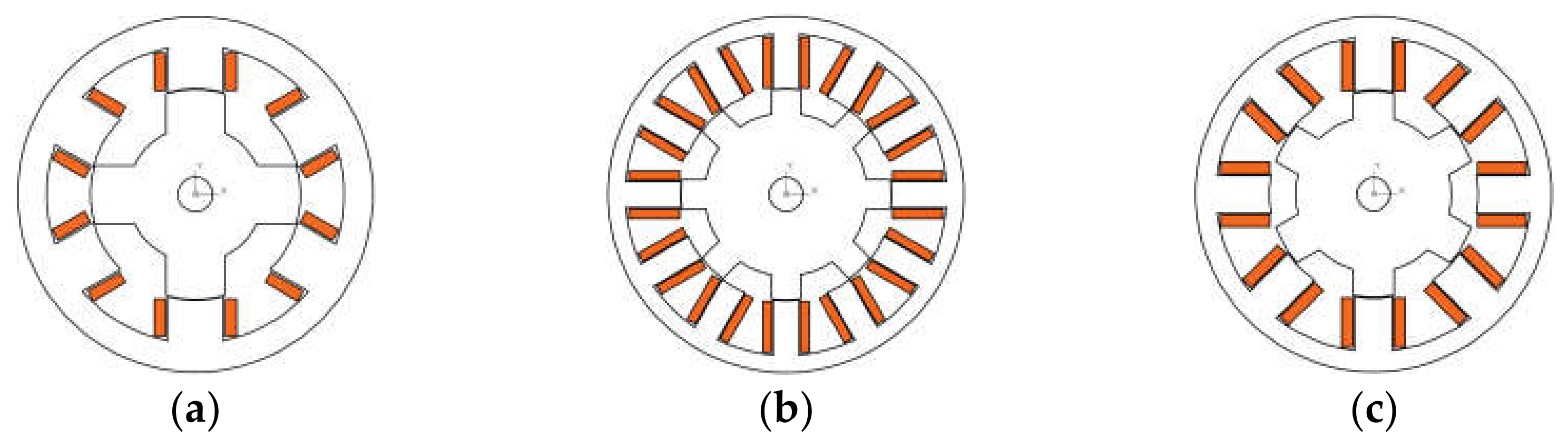
For fair comparison, the three motors, 3-phase 6/4 and 12/8, and 4-phase 8/6 SRMs are designed with the same dimensional restrictions. The stator outer diameter is fixed at 105 mm and stack length at 35 mm, so they roughly have the same outer volume considering the end-winding length will slightly vary. The shaft diameter is set to 10 mm. Since SRM has no permanent magnet, it is better to shorten the air-gap length as much as possible. Due to manufacturing limitations, it is set to 0.25 mm. The rated parameters are presented in Table 3 below and Figure 1 shows the topology of each motor.
In SRM, the generated electromagnetic torque is proportional to the number of phase , number of rotor poles, and the energy conversion area as shown in the equation below.
Judging by (3) alone, if more phase is used, less area of is required. is related to the current vs. flux characteristic, and thus less current is needed to produce the required torque. For the same phase and , the higher pole number will result in higher generated torque as well, so in order to produce the desired torque, less current can flow to the windings. This eventually may lead to higher efficiency because of smaller copper loss. However, as explained before, higher pole number may result in higher switching loss, and thus core loss and higher phase number means more power switched required that increases the size and price of the drive.
2.3. Characteristics Analysis of Proposed Motors
SRM relies on reluctance torque for its operation. In other words, rotor position is crucial in the operation. The torque in SRM can be expressed as follows,
The phase torque is proportional to the square of phase current and the change of phase inductance which can be calculated as,
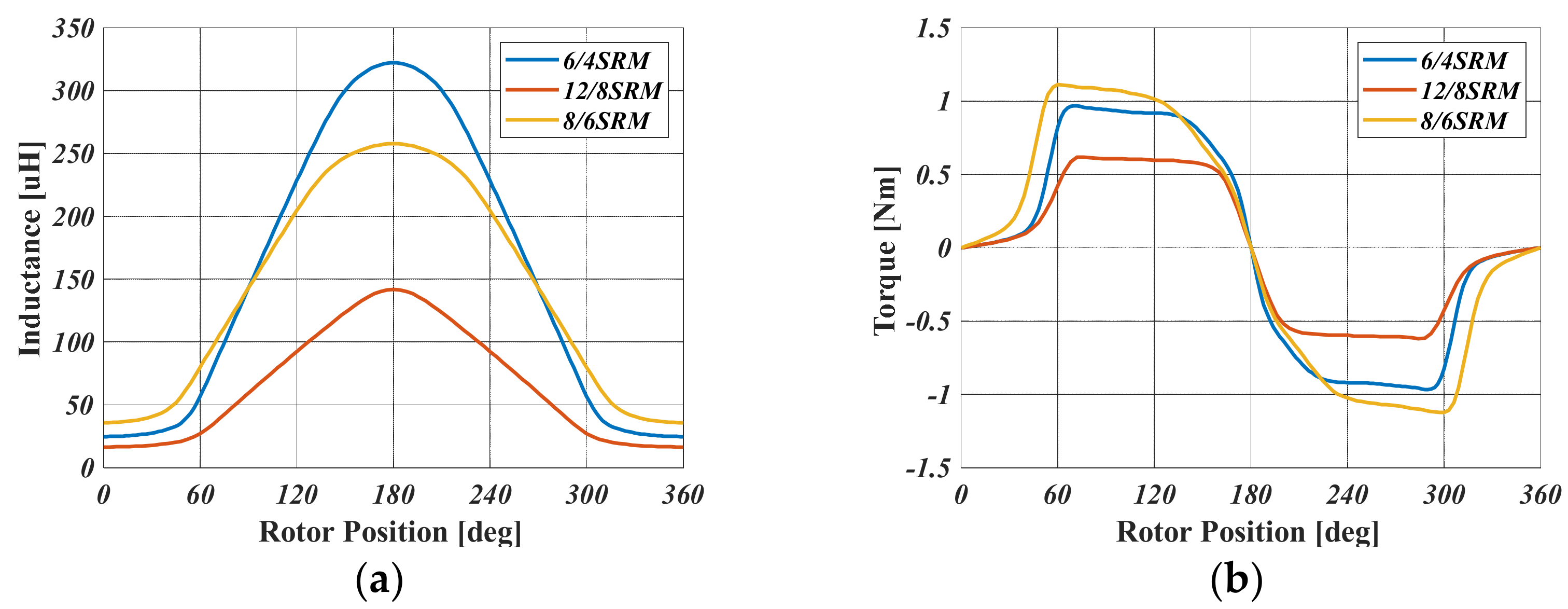
where is the phase flux linkage. Figure 2 shows the comparison of inductance and torque for the same current value at 50 A. The max/min ratio for 6/4, 12/8, and 8/6 SRMs are 13.0, 8.6, and 7.2, respectively. It can be confirmed that the value of inductance itself does not contribute to the torque generation. It is the slope that holds the important role. The higher the instantaneous gradient for inductance change per rotor position, the higher the torque will be. In this static simulation, the torque for 12/8 SRM is lower because the windings are connected in parallel (two poles each) and therefore for the same current, the torque is less. This result only states the phase torque generation capability for a given current and does not reflect the actual torque during operation since other phases are not considered. Later this can be seen in 12/8 SRM having similar RMS current magnitude as 6/4 type and still produces the same output torque.
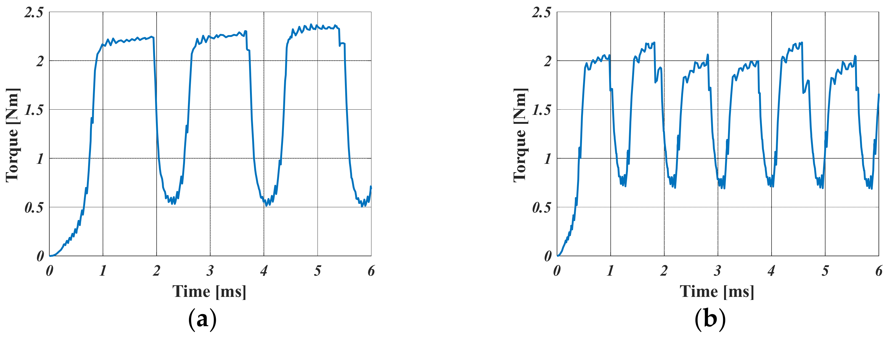
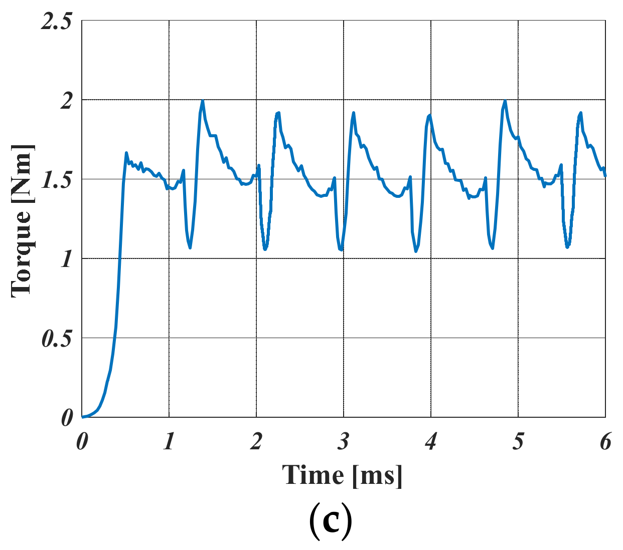
To reflect the actual torque profile, dynamic simulation in which switching on and off the phase periodically was performed. The resulting performance for each motor is showed in Figure 3. Unlike before, the profiles shown here is matched to have the same average torque at 1.7 Nm. It can be seen that the torque ripple is inherent due to the commutation between phases. As shown in the figure, more pole number means less torque ripple. It can be seen that the 8/6 SRM has the lowest torque ripple and 12/8 SRM produces less ripple than 6/4 SRM. More detail is presented in Table 4 below. The torque ripple is calculated as follows,
Based on the observations made in the design stage, the 4-phase 8/6 SRM is selected to be the actuator for the cooling fan because it has the highest efficiency and less current is required which reduces the burden on converter. It also has the lowest torque ripple, but in this particular application in which torque and speed ripples are not too important, this characteristic is ignored. However, if AHB which is the conventional converter for SRM is used, a total of eight power switches are required to operate the motor. Since the aim of this study is to develop a low-cost drive for the cooling fan, a modification to AHB is necessary which is explained in the next section.
3. Miller Converter for The Proposed 8/6 SRM
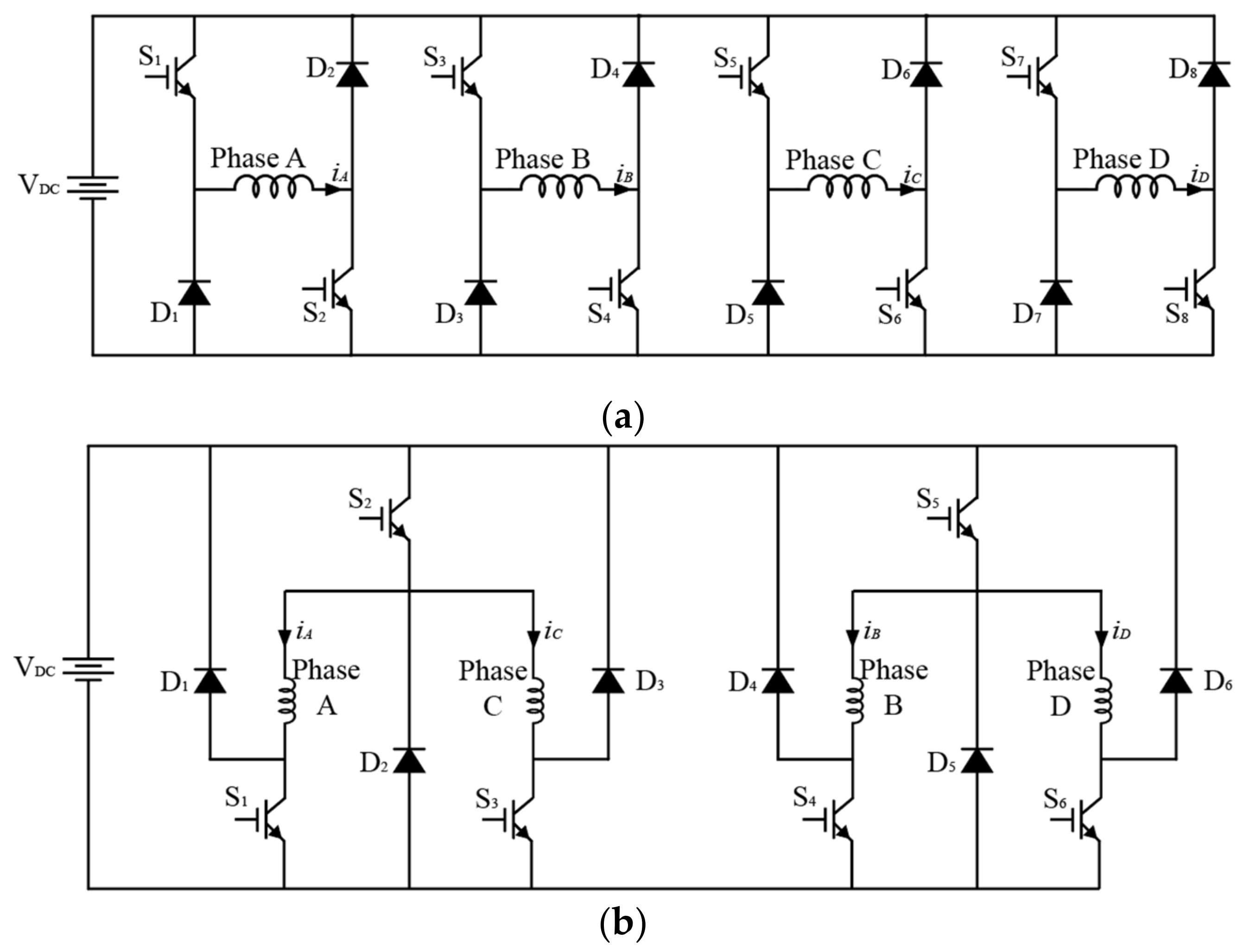
Miller converter or shared-switch topology was first introduced in [11]. The idea is to share the same switch and diode set between more than one phase and there are many configurations according to the number of phase (even or odd) as shown in [12,13]. The change only affects the upper switch, leaving the lower switches the same as AHB configuration and thus independent phase control is still possible. Figure 4 below shows the comparison of AHB and Miller converter for four-phase SRM.
As shown in the figure above, two phases can share the same upper switch so therefore only six switches are required. The control method for both converters is still the same, which is to give PWM (pulse width modulation) signal to the upper switch and simple on and off for the lower switches. Radiator cooling fan does not require precise control method for speed or torque. When the temperature rises, the fan operates to the rated speed and stays on until temperature drops. Therefore, only speed is controlled, and ripple can be ignored. The load type used in this simulation is fan load which can be calculated as follows,
where is the load that varies non-linearly with the speed, is the rated load set at 1.67 (Nm), is the actual speed, and is the rated speed set at 2800 (RPM). A simple PI (proportional–integral) gain is used to get the required speed.
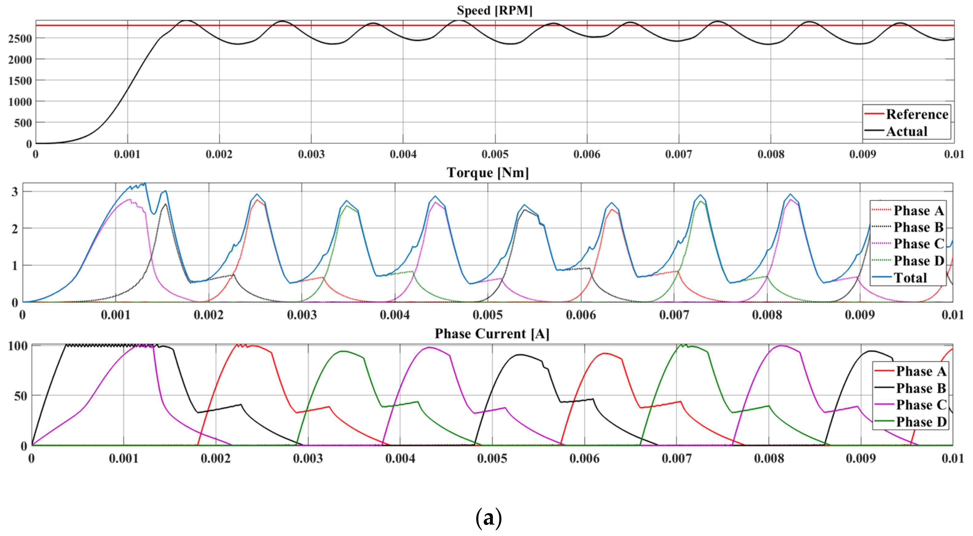
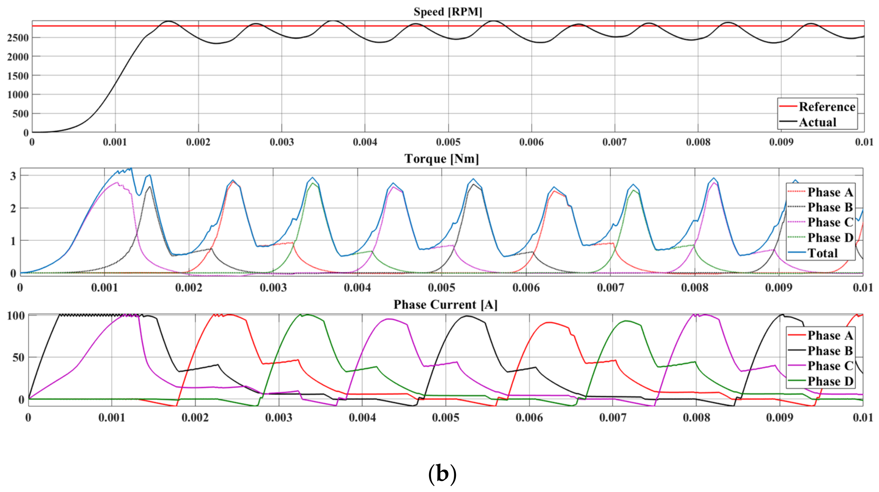
The result of changing AHB to Miller converter is shown in Figure 5. It can be seen that the speed and torque for both are the same. One big difference is when Miller converter is used, negative current flows on each phase which indicates that there is a small amount of current flowing in the opposite direction even though the phase has not been turned on yet. However, based on SRM torque principles in which torque is not affected by the polarity of the current, this small amount of “leak” generates positive torque which lowers the total instantaneous torque where it happens. Also, it can be observed that the negative current flows just before the corresponding phase is turned on, which means it happens near the commutation region. As was presented in (6), the negative current reduces the and thus increases the torque ripple. However, since in the proposed application ripple is not the main focus, we can safely change AHB to Miller converter since similar performance can be achieved.
4. Experimental Results
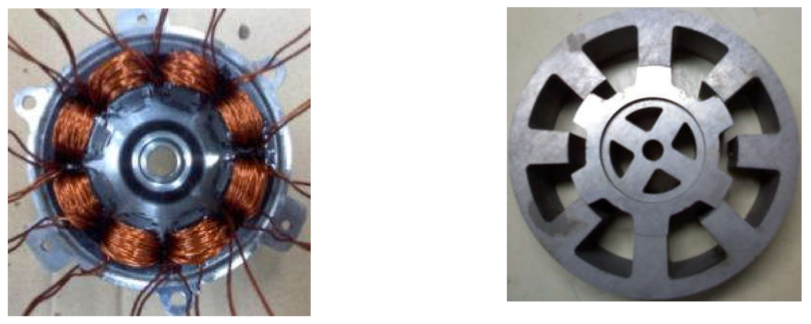
To verify the performance of the proposed motor, the 4-phase 8/6 SRM was manufactured and tested. Figure 6 shows the inside of the motor. As previously mentioned, SRM structure is very simple and easy to manufacture.
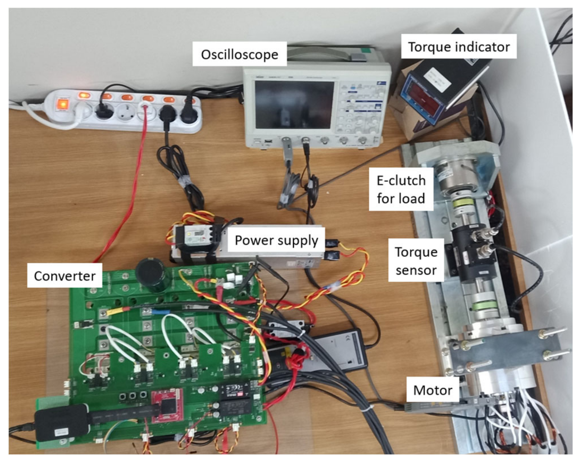
Experiments were carried with conventional AHB and Miller converter. For both, TMS320 F28335 from Texas Instrument is used as the DSP (Digital Signal Processor). Switching frequency to drive the IGBT is set to 20 (kHz). Power supply of 12 [V] is connected to supply the power to the motor. Figure 7 shows the experimental setup. A simple PI speed control is used to operate the motor to rated speed of 2800 [RPM]. Then the e-clutch (e for electronic) that acts as a brake is operated using another DC power supply so that the output torque of the motor is 1.67 (Nm). To be noted, this is our general experimental configuration available in lab. For fan application, much cheaper MOSFET switches can be used and a more compact converter can be manufactured. However, the point in this paper is to show the viability of switch reduction to reduce cost and the performance of proposed SRM regardless of switch type since the price reduction will be accordingly proportional.
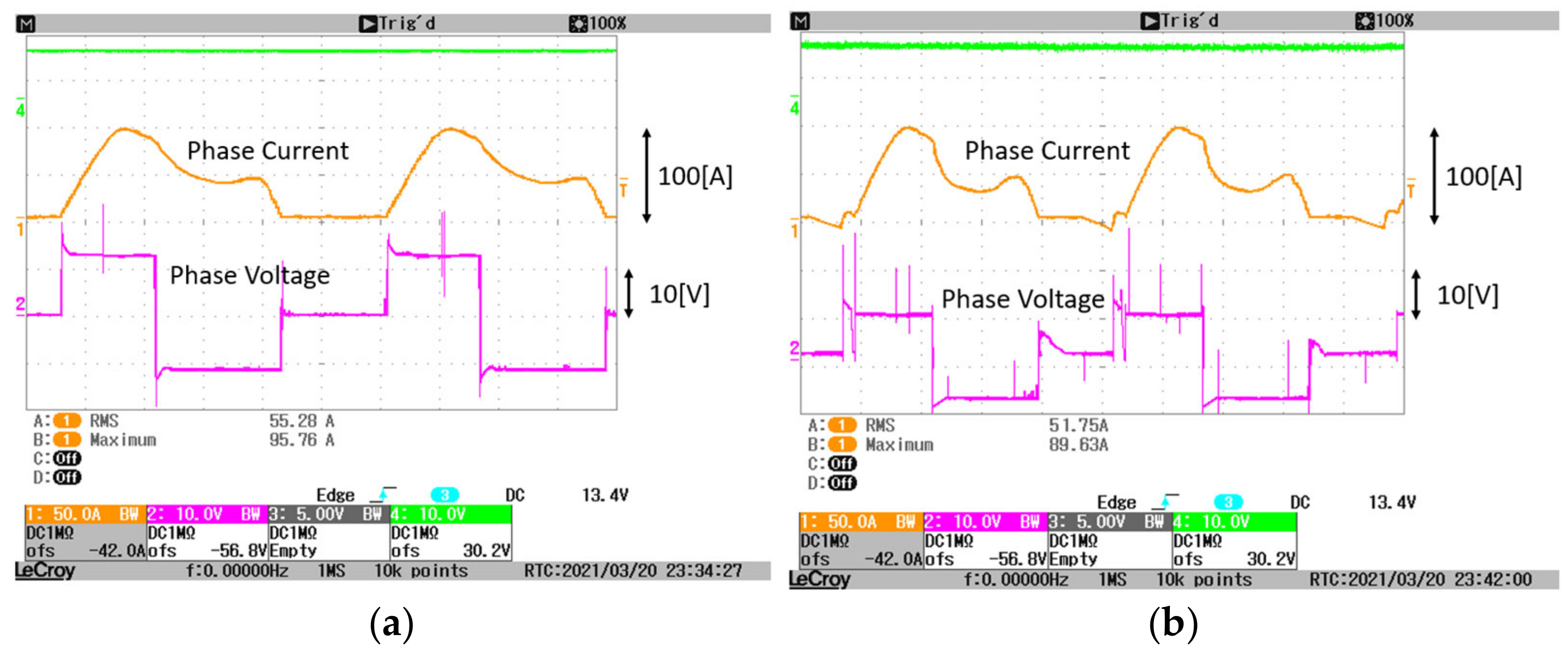
The experimental result is presented in Figure 8 below. It can be seen from the current waveform that they quite match the simulation. When Miller converter is used, the negative current exists before the current for the corresponding phase rises. This slightly reduces torque and thus more current is required to produce the same output power. The efficiency for AHB and Miller is 82.5% and 80.4%, respectively. Another thing that can be observed is the electric noise. Compared to AHB, Miller converter produces much higher EMF and thus is not suitable in EMF-sensitive environments.
5. Conclusions
In this paper, the design consideration and selection process of a cost-effective switched reluctance drive for vehicle radiator cooling fan are presented. The aim is to reduce the overall cost down while still maintaining performance. SRM is well-known for its high ripple, but since the target application is not sensitive to ripple, the selection is based on efficiency and current rating to reduce the burden on converter. The study can be summarized as follows:
- Three general SRM, 3-phase 6/4, 3-phase 12/8, and 4-phase 8/6 types were initially designed to satisfy the output requirements.
- The 4-phase 8/6 SRM was selected because it satisfies the requirement with the highest efficiency and lowest current rating.
- A problem with the selected motor is that it requires eight power switches if SRM conventional converter is used and thus this adds to the cost.
- In Miller converter, one upper switch can be shared among two phases.
- Therefore, the designed 8/6 SRM is then paired with Miller converter as the low-cost solution.
- Simulation and experiments were performed to verify the proposed idea.
- The result shows that Miller converter is interchangeable with conventional AHB as an alternative in this application with slightly reduced efficiency from 82.5% to 80.4%.
Author Contributions
Conceptualization, I.S. and K.-I.J.; methodology, K.-I.J.; validation, I.S. and M.H.S.; formal analysis, G.F.L.; investigation, G.F.L. and M.H.S.; resources, I.S.; writing, G.F.L.; visualization, G.F.L.; supervision, J.-W.A.; project administration, J.-W.A.; All authors have read and agreed to the published version of the manuscript.
Funding
This work was partially supported by “Human Resources Program in Energy Technology” of the Korea Institute of Energy Technology Evaluation and Planning (KETEP), granted financial re-source from the. Ministry of Trade, Industry & Energy, Republic of Korea. (No. 20184010201700) and “National Research Foundation of Korea” of Republic of Korea. (No. NRF-2020R1G1A1012756).
Conflicts of Interest
The authors declare no conflict of interest.
References
- Pop, F.P.; Popa, D.; Marţiş, R.; Marţiş, C.; Pop, A. Comparative Analysis of Rare Earth-Less Electrical Machines for 48 V Automotive Cooling Fan Applications. In Proceedings of the 14th International Conference on Engineering of Modern Electric Systems (EMES), Oradea, Romania, 1–2 June 2017; pp. 180–183. [Google Scholar] [CrossRef]
- Gieras, J.F. Permanent Magnet Motor Technology: Design and Applications, 3rd ed.; CRC Press: Boca Raton, FL, USA, 2009. [Google Scholar]
- Ye, J.; Huang, Z. Design and Realization of Control System of Brushless DC Motor Based on ARM. J. Phys. Conf. Ser. 2018, 1087, 042070. [Google Scholar] [CrossRef]
- Cui, J.; Kramer, M.; Zhou, L.; Liu, F.; Gabay, A.; Hadjipanayis, G.; Balasubramanian, B.; Sellmyer, D. Current Progress and Future Challenges in Rare-Earth-Free Permanent Magnets. Acta Mater. 2018, 158, 118–137. [Google Scholar] [CrossRef]
- Adly, A.A.; Huzayyin, A. The Impact of Demagnetization on the Feasibility of Permanent Magnet Synchronous Motors in Industry Applications. J. Adv. Res. 2019, 17, 103–108. [Google Scholar] [CrossRef] [PubMed]
- Bilgin, B.; Jiang, J.W.; Emadi, A. (Eds.) Switched Reluctance Motor Drives: Fundamentals to Applications; CRC Press: Boca Raton, FL, USA, 2019. [Google Scholar]
- Cheng, H.; Chen, H.; Xu, S.; Yang, S. Adaptive Variable Angle Control in Switched Reluctance Motor Drives for Electric Vehicle Applications. J. Power Electron. 2017, 17, 1512–1522. [Google Scholar] [CrossRef]
- Chaple, M.; Bodkhe, S.B.; Daigavane, P. Four Phase (8/6) SRM with DTC for Minimization of Torque Ripple. Int. J. Electr. Eng. Educ. 2019, 1–14. [Google Scholar] [CrossRef]
- Hu, Y.; Gan, C.; Cao, W.; Zhang, J.; Li, W.; Finney, S.J. Flexible Fault-Tolerant Topology for Switched Reluctance Motor Drives. IEEE Trans. Power Electron. 2016, 31, 4654–4668. [Google Scholar] [CrossRef] [Green Version]
- Ahn, J.-W.; Lukman, G.F. Switched Reluctance Motor Drives. Modeling Simul. Control Electr. Drives 2019, 275–324. [Google Scholar] [CrossRef]
- Kumar, V.M.; Vinoth Kumar, K.; Saravanakumar, R. Switched Reluctance Motor Converter Topologies: A Review. In Innovations in Electrical and Electronics Engineering; Saini, H.S., Srinivas, T., Vinod Kumar, D.M., Chandragupta Mauryan, K.S., Eds.; Springer: Singapore, 2020; pp. 55–63. [Google Scholar] [CrossRef]
- Pires, V.F.; Pires, A.J.; Cordeiro, A.; Foito, D. A Review of the Power Converter Interfaces for Switched Reluctance Machines. Energies 2020, 13, 3490. [Google Scholar] [CrossRef]
- Peng, W.; Gyselinck, J.; Ahn, J.; Lee, D. Torque Sharing Function Control of Switched Reluctance Machines with Reduced Current Sensors. CES Trans. Electr. Mach. Syst. 2018, 2, 355–362. [Google Scholar] [CrossRef]
- Krishnan, R.; Park, S.-Y.; Ha, K. Theory and Operation of a Four-Quadrant Switched Reluctance Motor Drive with a Single Controllable Switch-the Lowest Cost Four-Quadrant Brushless Motor Drive. IEEE Trans. Ind. Appl. 2005, 41, 1047–1055. [Google Scholar] [CrossRef]
Figure 1.
Topology of considered motors: (a) 3-phase 6/4, (b) 3-phase 12/8, and (c) 4-phase 8/6.

Figure 2.
Static characteristic comparison of proposed motors: (a) Inductance, (b) Torque a.

Figure 3.
Dynamic torque comparison: (a) 6/4, (b) 12/8, (c) 8/6 SRMs.


Figure 4.
Converter topology for 4-phase SRM: (a) Asymmetric half bridge (AHB), (b) Miller.

Figure 5.
Simulation result: (a) Asymmetric half bridge (AHB), (b) Miller.


Figure 6.
Proposed 4-phase 8/6 SRM.

Figure 7.
Experimental setup.

Figure 8.
Experiment result at rated condition: (a) Asymmetric half bridge (AHB), (b) Miller.


Table 1.
Conventional phase and pole combinations.
| Phase | Structure | Characteristics | Torque Ripple | Converter Price |
|---|---|---|---|---|
| Single | 4/4 | High speed, no self-start | Very high | Very low |
| Two | 4/2 | High speed, compact | High | Low |
| Three | 6/4 | All-around performance | Medium | Medium |
| 12/8 | High torque | Low | ||
| Four | 8/6 | High efficiency, high torque | Very low | High |
Table 2.
Value based on applications.
| Applications | [kNm/m3] |
|---|---|
| Small, total-enclosed | 2~5.5 |
| Common industrial | 5.5~20 |
| High performance servo | 10~40 |
| Aerospace | 20~60 |
| Large, liquid-cooled | 80~200 |
Table 3.
Design Target.
| Parameters | Value |
|---|---|
| DC-link voltage [V] | 12 |
| Rated speed [RPM] | 2800 |
| Rated torque [Nm] | 1.68 |
| Minimum efficiency [%] | 80 |
Table 4.
Dynamic performance comparison.
| Parameters | 6/4 SRM | 12/8 SRM | 8/6 SRM |
|---|---|---|---|
| Average torque [Nm] | 1.7 | ← | ← |
| RMS phase current [A] | 54.5 | 59.3 | 35.8 |
| Copper loss [W] | 106.32 | 55.8 | 61.7 |
| Core loss [W] | 20.7 | 37.6 | 33.0 |
| Efficiency [%] | 78.0 | 80.1 | 82.5 |
| Torque ripple [%] | 109.5 | 95.9 | 62.2 |
Publisher’s Note: MDPI stays neutral with regard to jurisdictional claims in published maps and institutional affiliations. |
© 2021 by the authors. Licensee MDPI, Basel, Switzerland. This article is an open access article distributed under the terms and conditions of the Creative Commons Attribution (CC BY) license (https://creativecommons.org/licenses/by/4.0/).
Share and Cite
MDPI and ACS Style
Son, I.; Lukman, G.F.; Shah, M.H.; Jeong, K.-I.; Ahn, J.-W. Design Considerations and Selection of Cost-Effective Switched Reluctance Drive for Radiator Cooling Fans. Electronics 2021, 10, 917. https://doi.org/10.3390/electronics10080917
AMA Style
Son I, Lukman GF, Shah MH, Jeong K-I, Ahn J-W. Design Considerations and Selection of Cost-Effective Switched Reluctance Drive for Radiator Cooling Fans. Electronics. 2021; 10(8):917. https://doi.org/10.3390/electronics10080917
Chicago/Turabian StyleSon, Ickjin, Grace Firsta Lukman, Mazahir Hussain Shah, Kwang-Il Jeong, and Jin-Woo Ahn. 2021. "Design Considerations and Selection of Cost-Effective Switched Reluctance Drive for Radiator Cooling Fans" Electronics 10, no. 8: 917. https://doi.org/10.3390/electronics10080917
Note that from the first issue of 2016, this journal uses article numbers instead of page numbers. See further details here.