Article

An Autonomous Grape-Harvester Robot: Integrated System Architecture

by
Eleni Vrochidou
1,
Konstantinos Tziridis
1,
Alexandros Nikolaou
1,
Theofanis Kalampokas
1,
George A. Papakostas
1,*,
Theodore P. Pachidis
1,
Spyridon Mamalis
2,
Stefanos Koundouras
3 and
Vassilis G. Kaburlasos
1
1
HUMAIN-Lab, Department of Computer Science, School of Sciences, International Hellenic University (IHU), 65404 Kavala, Greece
2
Department of Agricultural Biotechnology and Oenology, School of Geosciences, International Hellenic University (IHU), 66100 Drama, Greece
3
Laboratory of Viticulture, Faculty of Agriculture, Forestry and Natural Environment, School of Agriculture, Aristotle University of Thessaloniki (AUTh), 54124 Thessaloniki, Greece
*
Author to whom correspondence should be addressed.
Electronics 2021, 10(9), 1056; https://doi.org/10.3390/electronics10091056
Submission received: 1 April 2021 / Revised: 23 April 2021 / Accepted: 26 April 2021 / Published: 29 April 2021
(This article belongs to the Special Issue Control of Mobile Robots)

Abstract

:
This work pursues the potential of extending “Industry 4.0” practices to farming toward achieving “Agriculture 4.0”. Our interest is in fruit harvesting, motivated by the problem of addressing the shortage of seasonal labor. In particular, here we present an integrated system architecture of an Autonomous Robot for Grape harvesting (ARG). The overall system consists of three interdependent units: (1) an aerial unit, (2) a remote-control unit and (3) the ARG ground unit. Special attention is paid to the ARG; the latter is designed and built to carry out three viticultural operations, namely harvest, green harvest and defoliation. We present an overview of the multi-purpose overall system, the specific design of each unit of the system and the integration of all subsystems. In addition, the fully sensory-based sensing system architecture and the underlying vision system are analyzed. Due to its modular design, the proposed system can be extended to a variety of different crops and/or orchards.

1. Introduction

Agriculture technologies keep evolving in the recently introduced paradigm of Agriculture 4.0 [1]. The latter can be regarded as an extension of the Industry 4.0 paradigm to farming. Within Agriculture 4.0, emerging technologies such as robotics, Internet of Things (IoT), artificial intelligence and machine vision are combined with a common focus on sustainable crop management [2]. Furthermore, the advent of autonomous intelligent systems has led to the development of robust agricultural robots, namely agrobots [3,4,5]. Agrobots can better handle the variability of crops and hence reduce environmental impacts while increasing food supply and improving economic sustainability [2,3].
Research often focuses on interactive agrobots that can operate on a crop scale especially with dexterous tactile skills. Toward this end, agrobots have been introduced for precision agriculture tasks such as weeding, harvesting, spraying, pruning, watering, etc. The design of a harvesting cherry tomato robot was presented in [6]; the robotic system consists of a stereo-vision unit, an end-effector, a manipulator, a fruit collector and a railed vehicle. The design concept of an autonomous kiwifruit-picking robot was reported in [7]; the robot follows instructions transmitted via a radio link and navigates autonomously combining Global-Positioning System (GPS) and machine vision; the system was equipped with four picking arms controlled by one processing core. In [8] a micro-dosing system for the precise application of herbicides was developed; the overall system includes an autonomous ground robot, a camera and a micro-dosing system. Another work [9] described an autonomous apple-picking robot; the main parts of the system are a traveling device, a vision system and a robotic arm with a gripper. The development of a strawberry-harvesting robot was presented in [10]; the system consists of a red-green-blue depth (RGB-D) camera, a gripper and a robotic arm, mounted on an autonomous wheeled robot. An autonomous weeding mobile platform, namely AgBot II, offers three different mechanical implements depending on the detected weed namely an arrow hoe, a tine and a cutting tool [11]. Most of the reported mobile robots in the literature are task-specific. Task-specific agricultural robots are also commercially available, including Harvest CROO for strawberries harvest [12], GUSS for orchard spraying [13], Oz, Ted and Dino for weeding [14]. Commercial multi-purpose robotic platforms, designed for more than one particular agricultural operation, have also been reported, including Digital Farmhand [15], Farmdroid [16] and Husky [17].
Our special interest here is in grapes. It is well-known that the quality of produced grapes is highly affected by viticultural practices such as defoliation, lateral shoot removal and green harvest [18,19]. Regarding high-value crops like wine grapes, canopy management, pre-harvest, post-harvest and harvest operations are considered to have a considerable effect on wine quality. Agrobots are expected to support viniculture by saving human labor by performing viticultural operations with the dexterity of an experienced worker. Toward this end, this work presents a crop-scale multi-purpose autonomous grape harvester robot, or ARG for short, designed to carry out the viticultural tasks of harvest, green harvest and defoliation instead of a skillful worker. All operations are designed to allow personalization depending on the user preferences and are performed by custom-made end-effectors. Moreover, harvest is carried out homogeneously, in the sense that only grapes of a similar degree of maturity are harvested. The overall system includes three interdependent units: (1) an aerial unit, (2) a remote-control unit and (3) the ARG ground unit. The use of heterogeneous multi-modal units provides opportunities for targeted vineyard management and control of the overall system. The aerial unit provides images of the vineyards. The remote-control unit uses the images to build the vineyard maps and define all possible navigation paths. The remote-control unit allows the user to design an operation plan for the ARG ground unit to execute. The user can select between three different viticulture operations that may personalize and sends the operation plan to the ARG ground unit. The ARG navigates in the vineyard corridors, collects sensory data displayed to the remote-control unit and performs the selected viticultural operation in areas specified by the user. The objectives of this study are to describe the developed ARG harvester robot regarding (i) hardware design, referring to system architecture, interoperability and integration of hardware components, as well as (ii) software design referring to procedural flows, functionalities, integrated algorithms and personalization parameters. Due to its modular design, the proposed system can easily be adapted to similar agricultural operations regarding alternative crops.
The rest of the paper is structured as follows: Section 2 presents related work regarding viniculture agrobots. Section 3 details all system components, ARG design and workflows of the agricultural tasks. Section 4 describes ARG system integration. Discussion and future work are presented in Section 5. Finally, Section 6 concludes by summarizing the contributions of this work.

2. Related Work

Viniculture agrobots are rather scarce in the literature. The GRAPE project [20] is an autonomous ground robot with a robotic arm for plant health monitoring and targeted pheromone dispenser distribution; the robot operates by a user-friendly interface. In [21] a terrestrial robot is presented that can determine plant health, monitor the path in the vineyard and apply micronutrients to grapes. An earlier multi-purpose agrobot [22] was developed for harvesting, berry thinning, spraying and bagging; the system consisted of a manipulator, a visual sensor, a traveling device and alternating end-effectors. A cost-effective robot for crop monitoring tasks in mountain vineyards was presented in [23]. An updated version of the latter robot was reported in [24] able to navigate and carry out monitoring and harvesting tasks in steep slope vineyards. The design aspects of a semi-autonomous spraying robot were presented in [25]. The work in [26] describes an autonomous robot system for the automatic pruning of grapevines; a stereo-vision system extracts the three-dimensional (3D) model of the grape trees and a robotic arm carries out pruning. The VINBOT robot [27] was designed to optimize yield management and perform vineyard yield estimation. A multi-purpose robotic platform was developed for vineyard management using an autonomous vineyard scouting robot, namely VineRobot [28]. Table 1 includes the functionalities and basic features of all aforementioned related works regarding viniculture agrobots.
The aim of Table 1 is to highlight the main gap in viniculture agrobots that this work aims to fill. The proposed agrobot can deal with three different viticultural operations, introducing personalization parameters for all tasks. Green harvest and defoliation have not been implemented before by any other agrobota, as can be seen in Table 1, and none of the existing methods allows for the personalization of tasks. This is the main gap that this work aims to fill. In the proposed system, for harvest, personalization refers to the degree of maturity toward homogeneously harvested grapes. For the green harvest, the user can select the percentage of grapes bunches to be left in each vine tree, while for defoliation the user can define the percentage of leaves to be removed (see Section 3.2.1). At this point, it is worth mentioning that this work is the main concept of an ongoing project namely Personalized Optimal Grape Harvest by Autonomous Robot (POGHAR) [29]. Additionally, this work combines hardware design, interoperability and integration of devices along with procedural flows for all three viticultural operations, whereas none of the related work covers similar content. All machine vision algorithms that support these operations are referenced, leading to implementations that have already been done and their accuracy has been demonstrated at simulation level (see Section 3.2.1).

3. Materials and Methods

An overview of the proposed system is detailed in this section. More specifically, all units of the main system are analyzed. Particular importance is given to the ARG ground unit. The basic elements of ARG, which are the wheeled mobile robot and the manipulator, are described thoroughly; hardware, system design, interoperability of devices, procedural flows of all tasks, methodologies, machine vision algorithms and parametrization of agricultural tasks are presented.

3.1. System Overview

The overall system mainly consists of three units: (1) an aerial unit, (2) a remote-control unit and (3) the ARG ground unit. Figure 1 conceptually shows the system architecture, as well as the manner the three units interact with one another. Table 2 includes analytically the bill of materials (BOM) used per unit.
The aerial unit concerns an octocopter drone with an RGB camera mounted on it. Aerial surveillance provides intelligence to the ground unit regarding the field observation toward customized mission planning. More specifically, the drone flies on request over vineyards with favorable weather conditions and acquires images. The latter are used to derive the 3D micro-structure maps of the vineyards in order to calculate robot navigation paths along grapevine corridors. Details regarding this step of the implementation can be found in [30]. The evaluation of the proposed algorithm for navigation paths extraction reported average accuracy in terms of mean percentage error (MPE) for eight tested fields of 0.99%.
The remote-control unit is the information management and monitoring system presented in [31]. The remote-control unit is the communication channel between the human user and the ARG ground unit that receives and transmits data from and to the ARG ground unit. This unit enables for personalization of agricultural practices. Note that applied practices depend on the user’s intention, as well as the grape variety. In conclusion, adjustable grape management is enabled by the remote-control unit. Through this unit, the user designs the operation plan and transmits it to the ARG, while at the same time ARG transmits real-time sensory data notifying the user for both the environment and its functional status. Therefore, the user provides ARG with a personalized navigation plan that consists of selections of routes between all possible vineyard navigation paths that have been extracted [30].
The ARG ground unit is the autonomous multi-purpose agrobot that works in the field. It comprises two main hardware components, namely a manipulator and a wheeled mobile robot. Each aforementioned hardware component includes several specialized devices as shown in Table 2.
In particular, on the manipulator are mounted customized end-effectors, a 3D camera and artificial lighting, whereas on the wheeled mobile robot are mounted a 3D camera, several sensor devices, artificial intelligence (AI) computing devices and system power batteries. In-field sensory data, collected by the ARG, ground unit provide information regarding the robot’s status, e.g., battery level, connectivity, as well as working environment information regarding humidity, temperature, live streaming, etc. Machine vision and data analysis algorithms process the aforementioned data toward a sensible decision making.
The design architecture proposed here is in-line with the technological requirements of ARG for supporting harvest, green harvest and defoliation, as identified in [32]. It should be mentioned that all selected hardware components included in Table 2 have resulted after extensive research between the most up-to-date and efficient materials that can meet the specifications set in [32]. For the ARG ground unit, a crucial limitation for the choice of the mounted hardware was the maximum allowable load, which could not exceed 65 kg. This latter feature determined the selection of the particular manipulator. In what follows, the ARG ground unit, as well as its operation are further detailed.

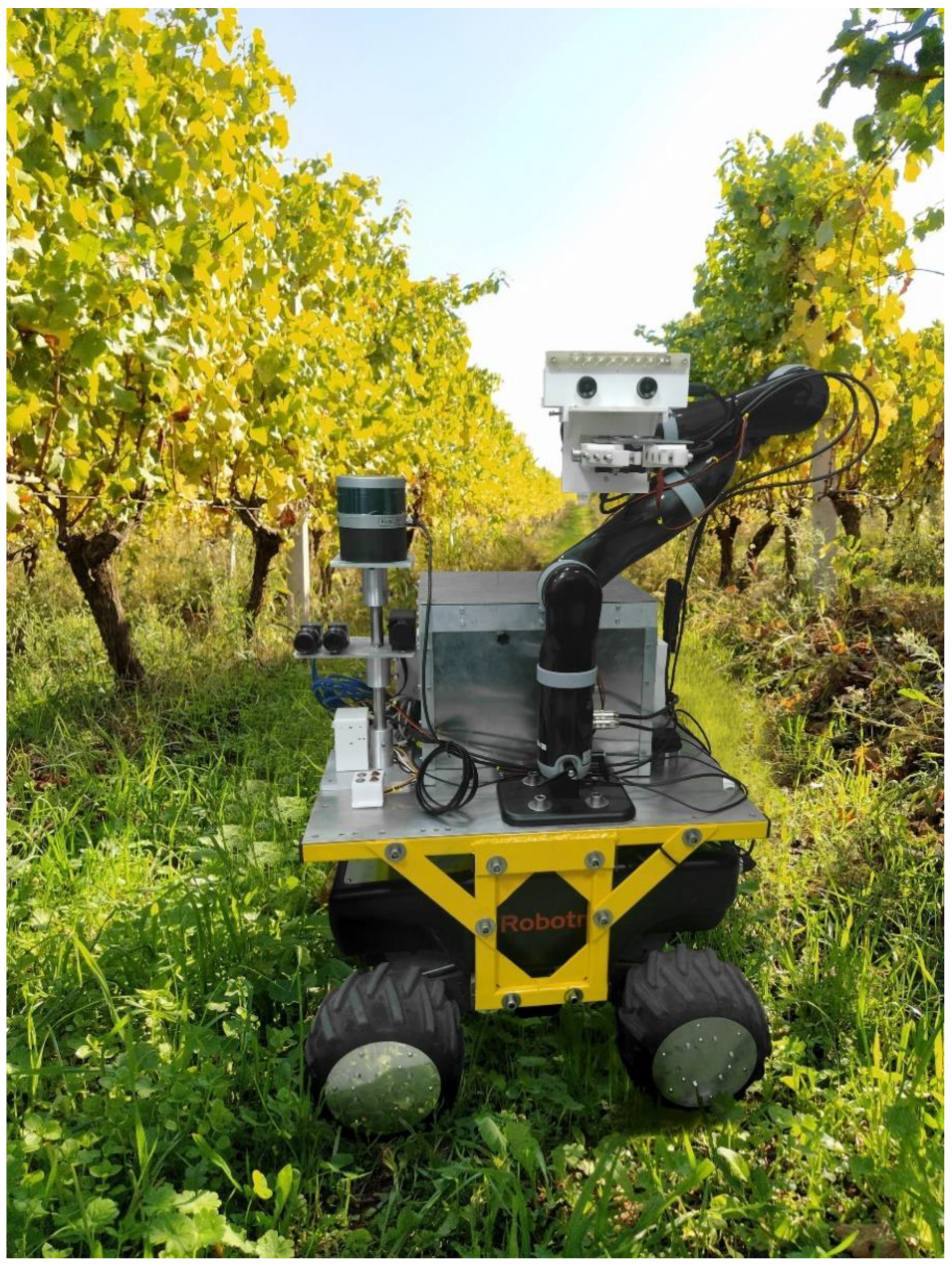
3.2. The ARG Ground Unit

The prototype hardware-assembled ARG ground unit is shown in Figure 2. The manipulator is mounted on the wheeled mobile robot vertically and on its left side. On the right side of the wheeled mobile robot, there is an insulated box containing two Jetson TX2 boards, a battery (LiFePO4 50 Ah @ 24 V DC) and all necessary electronic devices. The box keeps the equipment protected from external conditions, e.g., from the dust that rises with the movement of the vehicle in the field. The above box placement allows the manipulator to work only on the left side of the vineyard. Therefore, in case ARG needs to work on the right side of the vineyard, then it has to navigate along the vineyard corridor in the opposite direction.
The data acquisition system consists of the following parts:
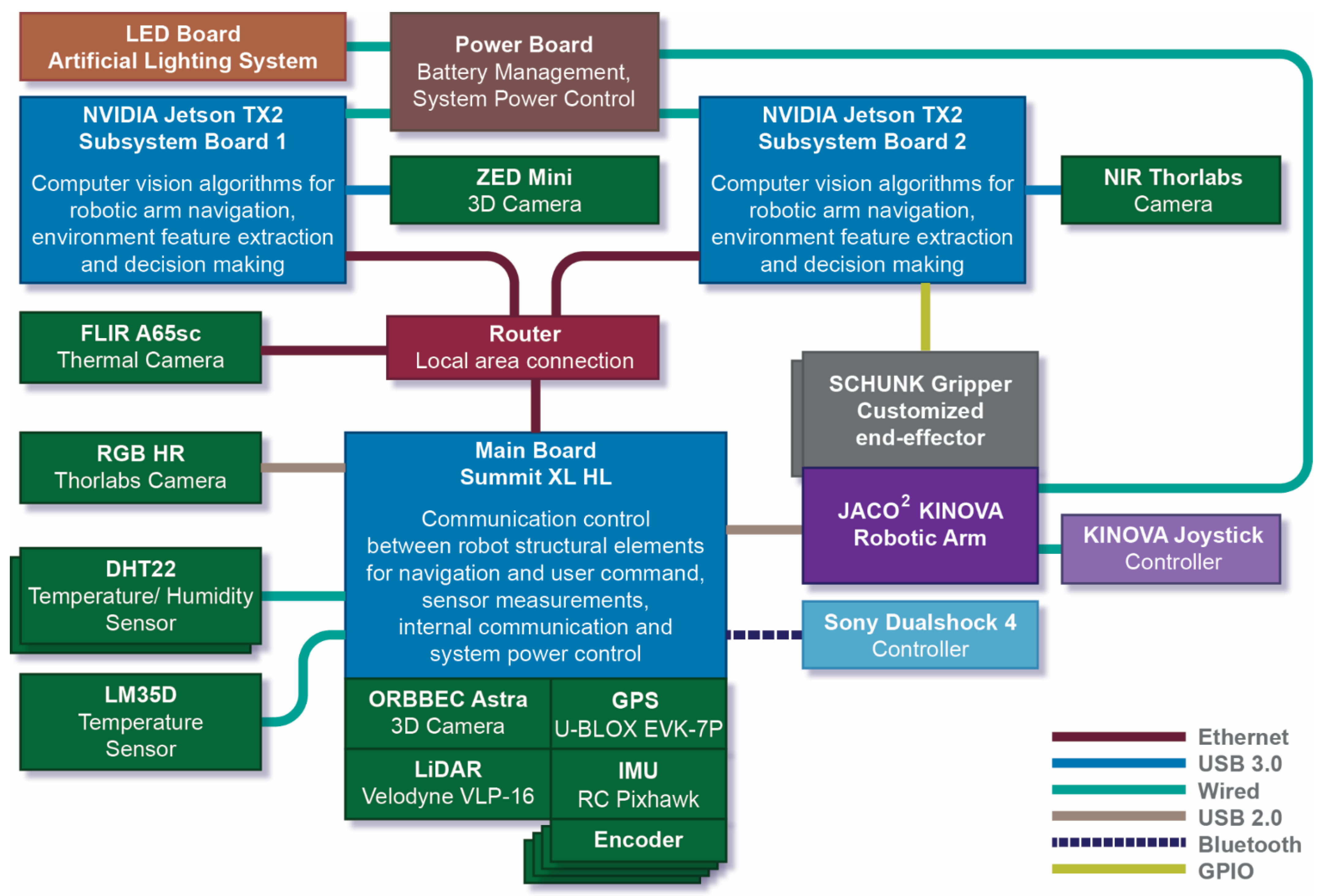
  • Environmental sensors, which include two DHT22 temperature and humidity sensors as well as one LM35D temperature sensor. More specifically, one DHT22 is placed inside the box containing electronic circuits, batteries and connections, for malfunction overheating monitoring, whereas the other DHT22 is placed externally on the robot vehicle for environmental measurements. Note that a DHT22 sensor measures humidity in the range from 0% to 100% with 2–5% accuracy and temperature in the range from 40 to +80 degrees Celsius with ±0.5 degrees accuracy. The LM35D sensor enhances the accuracy of external temperature measurements.
  • A ZED Mini 3D camera mounted on the robotic arm. This is the main visual sensor of the system. ZED Mini provides a streaming video sequence that can be monitored from the remote-control unit. Frames are used for: (1) grape cluster and leaves detection [33], (2) grape stem detection [34], (3) harvest crate detection [35], (4) grapevine trunk detection [36], (5) ripeness estimation and yield time prediction [37] and (6) grapes defect detection.
  • Three auxiliary cameras are mounted on the left side of the wheeled mobile robot on a fixed basis. The high resolution RGB and NIR cameras are placed on one side, whereas on the other side is placed the FLIR camera. The two synchronized NIR and RGB cameras are placed at a fixed distance of 3.5 cm from one another. These cameras are used to capture images from the vineyard rows in order to calculate vegetation and temperature indices. Vegetation indices are used to characterize areas in terms of vegetation density, allowing the user to have an overview of the vineyard and, from there, locate possible working areas. More specifically, FLIR provides thermal images and NIR provides spectral images to determine the density of green. FLIR camera is a high-cost equipment, therefore underexplored. However, studies reveal the correlation between FLIR thermal images with vegetation indices [38]. All measurements are displayed on the remote-control unit on the vineyard maps [29]. The user can consult on equipotential measurements maps in order to drive the robot to areas of his/her choice, according to the values of indicators related to ripeness and/or vegetation [39].
  • An ORBBEC Astra 3D camera, embedded on the wheeled mobile robot. This camera is used for navigation and it is embedded on the front of the wheeled robot. The camera recognizes harvest crates [35] as well as vine trunks [36] and uses them as markers. The ARG pauses in front of either a harvest crate or a vine trunk and carries out a specific agricultural task. In addition, the camera provides an RGB-D map of the field used for obstacle detection. Due to the 65 cm width of the ARG ground unit, combined with the 220 cm standard width of vineyard corridors, it is dangerous for the crops and fruits and difficult for the robot to navigate performing obstacle avoidance in the corridors. Therefore, in case the robot senses an obstacle, it stops navigation and informs the user of its exact location and the status, through the remote-control unit. In general, vineyards are considered semi-structured environments. The challenge for ARG is to move dynamically along the pre-defined vine corridors on uneven, heterogeneous, or muddy soil at a fixed safe distance from the crops line. Obstacles inside the vineyard corridors are considered non-existing and rare, therefore, were not assumed in the context of this work.
  • A GPS sensor, to locate the ARG and display in real-time its position on vineyard maps through the remote-control unit. Accurate location is not confirmed with the GPS. For this reason, GPS is not used for localization purposes, but only for the approximate visualization of ARG on the computer interface. To ensure the safe operation of ARG and minimize damage risks to both ARG and crops, additional sensory information is used for ARG’s localization, as explained next. The GPS sensor is mounted on top of the wheeled mobile robot on its back.
  • A fusion of four encoders for odometry, an internal measurement unit (IMU) and a LiDAR for ARG localization [40]. A fusion of encoder data with IMU data results in an initial state estimation for ARG. Localization is further optimized by using the LiDAR. It is well known that multi-modal systems based on a combination of sensors provide more accurate and robust state estimation. LiDAR uses two algorithms to achieve optimal localization: (1) the iterative closest points (ICP) algorithm [41] to registrate the 3D point cloud data of 16 laser beam layers; thus, it builds a map tracking the robot pose in six full degrees of freedom (DoF) simultaneous localization [42], and (2) an algorithm for wall-following, based on the information of one LiDAR laser beam; this algorithm provides the robot with a fixed distance from the working side. In order to maximize its viewing angle and scanning area, the LiDAR is adjusted on the wheeled robot on an elevated aluminum base. Thus, the interference of the LiDAR with the robotic arm or the box is avoided. The IMU sensor is located inside the wheeled mobile robot.
The GPS, LiDAR, IMU, encoders and the ORBBEC Astra camera are embedded on the wheeled mobile robot summit XL HL made by Robotnik and therefore it is powered by its battery LiFePO4 15 Ah @ 48 V DC. Α LiFePO4 50 Ah @ 24V DC battery supplies the manipulator and outputs various voltages through specialized voltage converters in order to power all the remaining sensors, ensuring approximately 5 h of autonomy. The system operation has been developed in Robot Operating System (ROS).
In addition to sensors, the basic elements that control the system are the main board of the wheeled robot and the two NVIDIA Jetson TX2 boards. Tasks of the main elements are listed below.
  • Main Board: The main board (motherboard) controls the wheeled robot regarding navigation and user commands. It assumes the internal communication between robot structure build in devices (IMU, GPS, LiDAR, Encoders, ORBBEC Astra) and all additional connected devices via three available USB 2.0 ports (JACO2 and RGB camera) or wire connection (DHT22 and LM35D sensors). The main board collects all data from the linked sensors and runs the algorithms listed in Table 3. The board provides its own power supply (LiFePO4 15 Ah @ 48 V DC battery) supporting all connected devices, apart from JACO2 which is powered by an additional power supporting board (Battery LiFePO4 50Ah@24V DC).
  • NVIDIA Jetson TX2: The main task of these two processing boards is to ensure high level autonomy of the system, communication tasks and machine vision algorithms along with feature extraction towards decision making, as shown in Table 3. Each board provides one USB 3.0 port. Board 1 is connected to ZED Mini, whereas board 2 is connected to the NIR camera; board 2 also controls the end-effector gripper. Both boards are connected via a Wi-Fi network with the remote-control unit as described in [31]. Data are communicated via the database, i.e., a MongoDB, that runs on the host computer of the remote-control unit to ARG and vice-versa. All information is transmitted inside JavaScript Object Notation (JSON) packets as JSON arrays. Both boards and all linked devices are powered by the power board (LiFePO4 50 Ah @ 24 V DC battery).

3.2.1. Manipulator

Depending on the agricultural operation, two different customized end-effectors (patent pending) are available and can be mounted on the 7-DoF robotic arm: one for harvest and green harvest and another for defoliation. The Kinova JACO2 is the robotic arm used due to its light weight and low power consumption. The modeling of JACO2 was presented in [43]. The analytic kinematic model was calculated and implemented in ROS for cross-validation. On the manipulator are mounted the ZED Mini 3D camera, as well as, an artificial lighting system in order to eliminate natural uncontrolled illumination or shadowing that affect the accuracy of machine vision algorithms and, additionally, to enable working during the night. The placement of the ZED Mini camera on the end-effector enhances surrounding sensing and improves target object identification and, ultimately, operation precision. Note that the Kinova JACO2 comes with a standard wired controller with a three-axis joystick mounted on a support. The latter controller is used in emergency cases such as entanglement of the arm inside the branches.
The workflow of the manipulator for the harvesting task is presented in Figure 3. During harvest, the objective is to collect grape clusters of a specific degree of maturity. Note that the degree of maturity is a conventional concept that varies for every grape variety and depends on the desired quality of the produced wine [44]. Therefore, for an accurate estimation of the harvest time, it is essential to monitor the grape ripening level. The harvesting task is accomplished by three machine vision algorithms executed in a row; grape cluster detection, ripeness estimation and grape stem detection. All the employed machine vision algorithms, as well as, the AI computing device on which they run are listed in Table 3. Table 3 also includes simulation performance results of the algorithms by mean pixel intersection over union (IU) or mean average precision (mAP). For the ripeness estimation algorithm, the error is computed as the distance between the calculated and predicted ripeness level. Methodologies referenced in Table 3 have been developed in previous works toward the implementation of the functionalities of the three agricultural tasks of harvest, green harvest and defoliation. Therefore, machine vision algorithms have already been proven to be of sufficient accuracy at simulation level. In order to connect the proposed system to the implemented algorithms, a description of the used model and the related task each algorithm is deployed to, are also provided in Table 3. More details on the parameters of the algorithms can be found in the corresponding references.
Table 3. Hardware computing devices and machine vision algorithms.
Computing
Device
Machine Vision
Algorithm
Description (Method, Model)Related TaskPerformance
NVIDIA
Jetson TX2
Board 1
Grape cluster
detection [33]
Semantic segmentation model
(Convolutional Neural Networks,
ResNet50_FRRN)
Harvest,
Green harvest
87.89%
IU
Ripeness
estimation [37]
Regression model
(Lattice Computing Modeling,
Intervals Numbers (INs) technique)
Harvest5.36%
Average
error
Defect
Detection [45]
Classification model
(Random Forest (RF) Classifier)
Harvest,
Green harvest
87% Classification accuracy
Leaves
detection [33]
Semantic segmentation model
(Convolutional Neural Networks,
MobileNetV2_PSPNet)
Defoliation83.45%
IU
NVIDIA
Jetson TX2
Board 2
Stem
detection [34]
Semantic segmentation model with regression
(Convolutional Neural Networks, UNET_MobileNetV2)
Harvest,
Green harvest
98.90%
IU
Main Board
Summit
Harvest crates
detection [35]
Object detection model
(You-Only-Look-Once version 3—YOLOv3)
Harvest,
Green harvest
99.74%
mAP
Vine trunk
detection [36]
Object detection model
(You-Only-Look-Once version 5—YOLOv5)
Defoliation73.2%
mAP
During harvesting, first, the model for the grape cluster detection is loaded. The model is supplied with frames taken with 8 frames per second (fps) from ZED Mini, it detects the grape clusters and starts the process from the nearest cluster. If no cluster is detected, the manipulator moves from the home position and covers a horizontal distance of 50 cm left and right, seeking for clusters. The selected scanning area is within a safe range according to the design specification i.e., opening angles of the robotic arm. This check is done twice and if no cluster is detected the robot moves to the next vine plant. In order to harvest a detected cluster, ripeness is estimated. Only clusters of a similar degree of maturity are harvested. If the cluster is fully ripened, the algorithm defines the center of its mass (CoMcluster) (x0,y0,z0), converts these coordinates from image points to space points and calculates the relative distance of the CoMcluster from preset reference points. These reference points are the edges of the cutting tool on the end-effector that are always evident in every frame. The manipulator moves towards the CoMcluster only on X and Y axes, until the CoMcluster is placed on the center of the image, between the reference points. When the cluster is centered on both X and Y axes, then the manipulator approaches the cluster by moving vertically on Z axis, and stops 2 cm from the target. From that distance, the stem of the cluster can be identified. At that point, information regarding the region of interest (ROI) is collected, such as extreme points (upper, left and right). The same process described for the grape cluster is repeated for the grape stem. After cutting the cluster from the stem, the manipulator returns to its home position and releases the cluster in a harvest crate placed underneath. Harvest crates are used as visual landmarks for navigation. More specifically ARG carries out all tasks after stopping in parallel with the harvest crates placed in front of vine trunks so as the home position of the manipulator is above the center of the harvest crate in order to straightforward place a collected cluster inside the crate. The aforementioned setup saves time from additional visual identification of harvest crates as well as from navigation of the manipulator toward it.
The workflow of the green harvesting task is illustrated in Figure 4. For green harvest and defoliation, vine trunks are used as visual landmarks for navigation. The ARG performs all tasks after stopping in parallel with the vine trunks. All removed leaves or clusters in those tasks are left to fall on the ground and outside any crate.
In green harvest, a percentage of the detected grape clusters is removed towards reducing grape load and, thus, improving the product quality [46]. The percentage is a requirement defined by the user on the personalization tab on the remote-control unit. First, the defected clusters are removed, i.e., rotten, sick, dry, damaged, and then the clusters are located on the outer edges of the vine tree. Removed clusters are thrown on the ground. The workflow for the green harvest is similar to that of harvest. The main difference is that the ripeness detection algorithm is now replaced with the defect detection algorithm. The “remove cluster” block in Figure 4 includes the grape cluster localization and stem detection as defined in the harvesting task (green blocks of Figure 3), the motion of the robotic arm and the cutting of the clusters by activating open/close of the scissor without returning the arm to its home position. In the beginning, all detected clusters are subjected to defect detection. Detected defected bunches are removed until the percentage selected by the user is achieved. If after this check the percentage of clusters to remove has not been achieved, then more distant clusters are removed until the user’s requirement is met.
On one hand, both the harvesting and the green harvesting task are implemented by a customized end-effector consisting of a robotic gripper, a specialized cutting tool (scissors) and 3D printed fingers, designed for cutting and holding the grape cluster from the stem without harming it. On the other hand, for the defoliation task, a custom-made specialized tool consisting of a robotic gripper replaces the harvesting end-effector and 3D printed specially shaped fingers with a rubber-coated internal surface, able to crumple and hold the leaf to remove it.
The workflow for the defoliation task is illustrated in Figure 5. Recall that defoliation is leaf removal from the base of the shoots towards enhancing the exposure of the grapes to the sun [47]. The defoliation task can be customized by the user from the remote-control unit. In particular, the user can define the percentage of the detected mass of leaves to remove. Note that defoliation calls for the removal of fewer leaves for white varieties to avoid loss of aromatic potential, and more leaves for red varieties to increase color and restrict plant aromas [48]. Thus, the ability of the proposed system to personalize the defoliation task is considered a novelty of great importance.
During defoliation, the ARG locates the first trunk next to the start point where defoliation will initiate and moves forward to the goal point by covering small parts of a predefined length (90 cm). The latter length is computed by considering the working area the robotic arm can cover according to specifications, i.e., opening angles, and applied torques, so the ARG can move forward and apply defoliation in marginally overlapping areas along the vineyard row until the end of the selected path. The percentage of leaves to be removed is a specification defined by the user on the personalization tab on the remote-control unit. The leaves detection algorithm defines the area of leaves in an image frame. The resulting images are 224 × 224 pixels size. Initially, the ROI where defoliation will be performed is defined; it is the area covering the lower half part of the image (112 × 224). Then, the ROI is divided into a grid, consisting of 4 rows and 8 columns, resulting in 32 equal square areas of 28 × 28 pixels size. The area of leaves is calculated for each square, and the 32 squares are sorted from the fullest to the emptiest. From this sorted set, we start summing up the leaves area, until α squares that include 80% of leaves in the ROI are defined. The remaining squares are excluded. This step is performed in order to exclude the boxes with only a few leaves and deal only with the full ones in order to avoid sending the robotic arm to defoliate in areas empty or almost empty. From the α selected boxes, we then try to define the ones with the most foliage where defoliation needs to be performed to remove the percentage of leaves set by the user. For this reason, we start summing up the leaves area of the α squares from the fullest to the emptiest, until we end up with the b squares that include the percentage (P%) of leaves of the total leaves area detected in the ROI. The CoM of the b squares is calculated and the robotic arm visits each CoM to remove the enclosed leaves. Every time the gripper closes, it moves back along the z-axis by 10 cm to detach the leaf from the stem. All decisions regarding the ROI size, grid size and distance values are defined by extensive trial-and-error procedures and depend on the position of the camera, which is fixed and remains stable every time it supplies the inference model with frames. The aforementioned camera is the ZED Mini camera that is mounted on the robotic arm. The camera is located constantly in the arm home position at a fixed distance from the vine trees foliage. Ιn this way we ensure consistency in the result. Figure 6 illustrates step-by-step the results of the proposed defoliation algorithm.
All agricultural tasks described in the procedural flows allow for customization. The user can select certain parameters from the remote-control unit to customize each task depending on individual applied practices. Table 4 includes the parameters that the user can define for all three tasks. All parameters have been extracted by a multidisciplinary team of experts including engineers, viticulturists and agronomists [32] and have been tested in the laboratory. At a simulation level, all methodologies and algorithms are sufficiently accurate. However, fine-tuning of both algorithms and parameters will be done in the field. Of course, failures are expected in the field, since in real conditions the performance of the methodologies depends on the setting of the parameters (fine-tuning), which can only be done in the field. At this point, it should be highlighted that all agricultural tasks produce wastes. Each wine producer manages wastes differently; some throw the defected grape clusters on the ground; others collect them in harvest crates; others leave them on the vine tree. Leaves removed from the defoliation are always left on the ground and recycled as fertilizer. As can be seen from Table 4, the proposed system allows the user to choose how to manage the waste generated by each agricultural task.
One challenge regarding the motion of the manipulator is to avoid collisions with both the equipment on the wheeled mobile robot and the natural environment. The vineyard is considered a semi-structured environment, but this has to do more with ARG navigation along vineyard corridors than with moving the manipulator. More specifically, branches, support wires, grown vegetation can potentially obstruct the movement of the manipulator. Therefore, in order to avoid collisions in this complex work environment, an algorithm was applied that runs continuously during all agricultural tasks. The aforementioned algorithm is a torque-based collision avoidance strategy [49]. The forces being exerted on each joint are checked at any time and a repulsive potential repels the robot away from obstacles, returning it to a safe position i.e., the home position. The repulsion potential field is also active for self-collision, along with joint limits that define a priori the safe working space for the manipulator. When working in unstructured fields, robotic systems need robust schemes, for safely interacting with the environment. The proposed scheme does not stand out for its robustness nevertheless, it is an acceptable choice for navigating safely in complex environments.

3.2.2. Wheeled Mobile Robot

The four-wheel mobile robot Summit XL HL by Robotnik was the basic mobile robot used in this project. It should be noted that the Summit can carry a payload of up to 65 kg, which is enough for the manipulator together with all the embedded systems, and can navigate on uneven terrain with safety. Two operating modes are available for the wheeled mobile robot, namely manual and autonomous. On one hand, a Dualshock 4 controller by Sony provides manual control via a Bluetooth connection; this mode is used in order to navigate the ARG to the starting point of the navigation path and back to the base in case of emergency. On the other hand, autonomous navigation is based on feedback from the wheel encoders, IMU and mainly from LiDAR; the robot navigates on predetermined paths in vineyard maps that are illustrated in the software application running in the remote-control unit, selected by the user. The selected paths are then transformed from GPS coordinates to robot poses and they are sent from the remote-control unit to the ARG. ARG is placed at the starting point of the path and then navigates from one pose to the next one with the help of the LiDAR using a wall-follower algorithm to keep a safe constant distance from the vine trees.
The embedded vision system of Summit, i.e., 3D ORBBEC Astra camera, is used to provide navigation cues that define the exact working area where ARG should stop and start working. More specifically, harvest crates [35], as well as, vine trunks [36] are used as visual cues. Note that harvest crates are located in front of each vine tree in order to collect the harvested clusters. However, harvest crates are not stable landmarks. Therefore, a vine trunk detection algorithm provides additional information regarding the exact stopping points. The aforementioned setup is functional and it permits ARG to navigate inside the vineyard corridors, turn when it reaches a corridor end, return along the same corridor or near it and stops in front of each vine tree on its way. The 3D camera can perceive obstacles and the system takes appropriate actions by informing the user through the remote-control unit. Navigation is effected with 0.5 m/s linear velocity and 0.2 rad/sec angular velocity. The flow regarding the movement of the wheeled mobile robot is shown in Figure 7.
All the tasks implemented in this work were developed in Python code using the Kinetic distribution of ROS installed on Ubuntu 16.04. ROS serves as a communication channel between software and hardware components of the robot via ROS messages. The robot uses a linear–quadratic regulator (LQR) controller [50]. Five main packages run on ROS, namely vision perception system, state estimation which includes localization and mapping, obstacle detection, task execution and navigation (Figure 8). The user personalizes the tasks on the interface of the remote-control unit and stores the task data on the database through which the robot receives all necessary task data. The robot obtains the navigation operational plan, extracted from the vineyard maps, and moves relatively from its current position to the received goal. The current pose and final goal are described by three variables: (x, y, θ); x and y describe the displacement of the robot from its current position in X and Y axes, and θ denotes the offset angle.
The task executor accepts the defined tasks regarding the motion and sends a task.
The task executor accepts the defined tasks regarding the motion and sends a task in the form of a string to the navigation package, which includes motion planning. The task executor also receives input from the visual perception system. Obstacle detection is performed using feedback from the ORBBEC Astra camera and LiDAR. State estimation includes the fusion of multiple sensors towards correcting the navigation trajectory.

4. System Integration

Figure 9 illustrates the integration and connectivity of ARG main structural elements. Τhe different color in lines represents the different ways of connecting the elements, according to the corresponding element tag. Sensors are represented by small boxes in green, while main elements are presented by big boxes in blue. The main elements communicate via a router local area Ethernet connection. The tasks of the main elements are described briefly in the figure.
The autonomous operation of ARG is defined by all previous workflows that describe how machine vision algorithms, the motion control of the wheeled robot and the manipulator are combined in order to implement three agricultural tasks.
System integration enables the ARG to employ the selected agricultural task all the time during navigating along the vineyard rows. The hardware and software architecture of ARG is presented in Figure 10. Surrounding boxes in green represent hardware modules, whereas inner boxes in deep blue represent software functions. The Ground Robot Node is the basic node that coordinates the system by synchronizing the information flow between all modules; it is responsible for the navigation tasks and performs image analysis. Navigation uses information from odometry as well as sensor streams and sends velocity commands to the wheeled robot. Image analysis includes machine-vision models, as well as, data processing algorithms. The Arm Motion Control Node is in charge of the motion of the robotic arm. The Subsystem Node calculates the target of the robotic arm, communicates with the wheeled mobile robot and it performs image analysis; besides, it links the robotic arm, the end-effector and the image analysis resulting from the ZED Mini camera, it handles sensory data from the camera, the robotic arm position status and the end-effector actions. Finally, the database refers to the MongoDB database where all data are stored from the remote-control unit to ARG and vice-versa.

5. Discussion

The engagement of agrobots promises operation cost-savings as well as reduction of both the required material resources and the yield losses in agriculture [3,51]. Furthermore, an imperative demand in agriculture is “manual dexterity” whose automation by machines can result in substantial benefits. For instance, in certain parts of the world such as in Europe, labor shortages of seasonal workers, unable to travel between regions, have caused fresh products accumulation as well as huge food losses. Therefore, automation of the harvest, as well as, of alternative tasks in agriculture that call for manual dexterity is expected to have a massive impact.
The advent of technology is directly related to software/hardware systems, leading to the simultaneous worldwide adaptation of robotics to an extended range of applications. Therefore, technological progress concerning power autonomy, machine vision algorithms, intelligence modeling, autonomous navigation and precise manipulation are expected to improve the functionality of agrobots at all levels.
According to the above, agrobots are still in their early stages and further applications will emerge gradually as an extension of breakthrough technologies. Presentation of detailed design principles and system architecture of agrobots aims at addressing potential problems to be solved by researchers working in the field. Challenges, problems, different designs and approaches need to be highlighted to gradually achieve successful adaption of innovative techniques and transfer knowledge to numerous tasks and different crops. Toward this end, the present work investigated the robotic design aspects of a multi-purpose vineyard agrobot, aiming at providing generic design guidelines.
A limitation of the proposed system is the need for a human controller of the remote-control unit. At this point, the user designs an operation plan for ARG, by selecting navigation paths and specific agricultural operations. Future work includes the investigation of replacing the human user with an optimization model that will be trained to design the optimal operation plan considering sensory data, available paths, etc. combined with additional features such as weather reports. However, even if the human controller is replaced with intelligent algorithms, still the human presence is considered necessary to monitor that the system responds properly and that both yield and ARG are not compromised in any way.
Typically, robots are employed in predictable, structured industrial environments, e.g., assembly lines. However, a typical agricultural environment is neither predictable nor structured. Therefore, a novel agrobot design should be sought, especially regarding its “intelligence modeling”. Note that it can be thought of as a cyber-physical system (CPSs). The latter is defined as mechanical devices endowed with both sensing and reasoning capacities toward a certain degree of autonomy. Toward this end, future work also includes intelligence modeling. Based on their advantages the potential of lattice computer (LC) models emerges especially promising for supporting integrated software/hardware systems [52] such as the one presented in this work, therefore, will be further investigated.
Another limitation of this work is the absence of an obstacle avoidance policy. Vineyard corridors are narrow enough for ARG to perform maneuvers, considering its size and heavy loads. In case an obstacle is sensed in its way, the ARG stops and informs the user through the remote-control station. The user then performs any necessary manual corrections to the ARG trajectory. This is time-consuming since the system needs to start over. Future work includes obstacle avoidance investigation, toward a more robust system.
An additional limitation of the proposed system is the power autonomy. At this point the system is powered by battery supplies, ensuring a finite working time. Future work includes the investigation of alternative energy sources such as solar panels.
In the context of this work, overall system performance results are not reported. However, this work references results of individual methodologies that implement basic tasks of the proposed system, such as the remote-control unit function [31], the navigation route mapping [30], the kinematic analysis of the robotic arm [43] and machine vision algorithms for detection of grape clusters and leaves [33], stems [34], harvest crates [35], vine trunks [36] and grape ripeness level [37]. These results will be validated in real scenarios covering a predefined range of vineyards of three well-known Northern Greece wine producers as part of a national research program [29]. Future work will also include the application of the overall system to alternative crops to investigate possibilities of adaptability of the proposed system and definition of possible limitations.

6. Conclusions

This work has presented a system architecture design aspects, development and integration regarding an autonomous agrobot for viticultural operations. The main characteristics of the proposed system are: (1) the crop scale application ability; (2) the multi-modal design based on three interdependent units (aerial, remote-control and ground unit); (3) the multi-purpose operational design allowing for harvest, green harvest and defoliation automation; note that green harvest and defoliation have not been investigated previously by other existing robotic systems; (4) the innovative personalization ability for all agricultural tasks toward personalized vineyard practices.
The aim of this work is to present the hardware design of the aforementioned overall system combined with the procedural workflows for all the applied tasks. More specifically, this work includes: (i) hardware specifications such as bill of materials, interoperability of devices, system architecture and system integration, and (ii) software specifications such as procedural flows, list of integrated algorithms, simulation results and personalization parameters. The limitations of the proposed system are also discussed.
Future work includes in-lab and in-field application of the integrated system, evaluation of all subsystems and fine-tuning. The proposed system design can be adapted to similar agricultural operations regarding alternative crops. Therefore, future applications will be investigated to evaluate the adaptability of the proposed system and to broaden the scope of this research. Future work also includes automated mission configuration based on sensory data, intelligent modeling for decision making, obstacle avoidance investigation and sustainable power supply, toward complete autonomy of the proposed system.

Author Contributions

Conceptualization, G.A.P., V.G.K. and T.P.P.; investigation, E.V., K.T., A.N. and T.K.; writing—original draft preparation, E.V., K.T., A.N. and T.K.; writing—review and editing, E.V., G.A.P., V.G.K., S.M., S.K. and T.P.P.; visualization, G.A.P., V.G.K. and T.P.P.; supervision, G.A.P.; project administration, G.A.P. All authors have read and agreed to the published version of the manuscript.

Funding

This research has been co-financed by the European Regional Development Fund of the European Union and Greek national funds through the Operational Program Competitiveness, Entrepreneurship and Innovation, under the call RESEARCH—CREATE—INNOVATE (project code: T1EDK-00300).

Conflicts of Interest

The authors declare no conflict of interest. The funders had no role in the design of the study; in the collection, analyses, or interpretation of data; in the writing of the manuscript, or in the decision to publish the results.

References

  1. Rose, D.C.; Wheeler, R.; Winter, M.; Lobley, M.; Chivers, C.-A. Agriculture 4.0: Making it work for people, production, and the planet. Land Use Policy 2021, 100, 104933. [Google Scholar] [CrossRef]
  2. Duckett, T.; Pearson, S.; Blackmore, S.; Grieve, B.; Chen, W.-H.; Cielniak, G.; Cleaversmith, J.; Dai, J.; Davis, S.; Fox, C.; et al. Agricultural Robotics: The Future of Robotic Agriculture. arXiv 2018, arXiv:1806.06762. [Google Scholar]
  3. Sparrow, R.; Howard, M. Robots in agriculture: Prospects, impacts, ethics, and policy. Precis. Agric. 2020, 1, 1–16. [Google Scholar] [CrossRef]
  4. Bechar, A.; Vigneault, C. Agricultural robots for field operations. Part 2: Operations and systems. Biosyst. Eng. 2017, 153, 110–128. [Google Scholar] [CrossRef]
  5. Bechar, A.; Vigneault, C. Agricultural robots for field operations: Concepts and components. Biosyst. Eng. 2016, 149, 94–111. [Google Scholar] [CrossRef]
  6. Feng, Q.; Zou, W.; Fan, P.; Zhang, C.; Wang, X. Design and test of robotic harvesting system for cherry tomato. Int. J. Agric. Biol. Eng. 2018, 11, 96–100. [Google Scholar] [CrossRef]
  7. Scarfe, A.J.; Flemmer, R.C.; Bakker, H.H.; Flemmer, C.L. Development of an autonomous kiwifruit picking robot. In Proceedings of the 2009 4th International Conference on Autonomous Robots and Agents, Wellington, New Zealand, 10–12 February 2009; pp. 380–384. [Google Scholar]
  8. Søgaard, H.T.; Lund, I. Application Accuracy of a Machine Vision-controlled Robotic Micro-dosing System. Biosyst. Eng. 2007, 96, 315–322. [Google Scholar] [CrossRef]
  9. He, B.; Liu, G.; Ji, Y.; Si, Y.; Gao, R. Auto Recognition of Navigation Path for Harvest Robot Based on Machine Vision. In IFIP Advances in Information and Communication Technology; Springer: Berlin/Heidelberg, Germany, 2011; pp. 138–148. ISBN 9783642183324. [Google Scholar]
  10. Xiong, Y.; Ge, Y.; Grimstad, L.; From, P.J. An autonomous strawberry-harvesting robot: Design, development, integration, and field evaluation. J. Field Robot. 2020, 37, 202–224. [Google Scholar] [CrossRef] [Green Version]
  11. McCool, C.S.; Beattie, J.; Firn, J.; Lehnert, C.; Kulk, J.; Bawden, O.; Russell, R.; Perez, T. Efficacy of Mechanical Weeding Tools: A study into alternative weed management strategies enabled by robotics. IEEE Robot. Autom. Lett. 2018, 32, 1184–1190. [Google Scholar] [CrossRef]
  12. Harvest CROO. Robotics. Available online: https://harvestcroo.com/ (accessed on 30 January 2021).
  13. GUSS. Autonomous Orchard Sprayers. Available online: https://gussag.com/ (accessed on 30 January 2021).
  14. Naïo Technologies. Automated Robots and Farming Tools. Available online: https://www.naio-technologies.com/en/agricultural-equipment/ (accessed on 30 January 2021).
  15. AGERRIS. The Digital Farmhand. Available online: https://agerris.com/the-digital-farmhand/ (accessed on 30 January 2021).
  16. FARMDROID. Available online: http://farmdroid.dk/ (accessed on 30 January 2021).
  17. CLEARPATH Robotics. Husky. Available online: https://clearpathrobotics.com/husky-unmanned-ground-vehicle-robot/ (accessed on 30 January 2021).
  18. Drenjančević, M.; Jukić, V.; Zmaić, K.; Kujundžić, T.; Rastija, V. Effects of early leaf removal on grape yield, chemical characteristics, and antioxidant activity of grape variety Cabernet Sauvignon and wine from eastern Croatia. Acta Agric. Scand. Sect. B Soil Plant Sci. 2017, 67, 705–711. [Google Scholar] [CrossRef]
  19. Martin, D.; Grose, C.; Fedrizzi, B.; Stuart, L.; Albright, A.; McLachlan, A. Grape cluster microclimate influences the aroma composition of Sauvignon blanc wine. Food Chem. 2016, 210, 640–647. [Google Scholar] [CrossRef] [PubMed]
  20. Roure, F.; Moreno, G.; Soler, M.; Faconti, D.; Serrano, D.; Astolfi, P.; Bardaro, G.; Gabrielli, A.; Bascetta, L.; Matteucci, M. GRAPE: Ground Robot for vineyArd Monitoring and ProtEction. In Advances in Intelligent Systems and Computing; Springer: Cham, Switzerland, 2018; pp. 249–260. [Google Scholar]
  21. Lopez-Castro, A.; Marroquin-Jacobo, A.; Soto-Amador, A.; Padilla-Davila, E.; Lopez-Leyva, J.A.; Castaneda-Ramos, M.O. Design of a Vineyard Terrestrial Robot for Multiple Applications as Part of the Innovation of Process and Product: Preliminary Results. In Proceedings of the 2020 IEEE International Conference on Engineering Veracruz (ICEV), Boca del Rio, Mexico, 26–29 October 2020; pp. 1–4. [Google Scholar]
  22. Monta, M.; Kondo, N.; Shibano, Y. Agricultural robot in grape production system. In Proceedings of the 1995 IEEE International Conference on Robotics and Automation, Nagoya, Japan, 21–27 May 1995; Volume 3, pp. 2504–2509. [Google Scholar]
  23. Neves Dos Santos, F.; Sobreira, H.M.P.; Campos, D.F.B.; Morais, R.; Moreira, A.P.G.M.; Contente, O.M.S. Towards a Reliable Monitoring Robot for Mountain Vineyards. In Proceedings of the 2015 IEEE International Conference on Autonomous Robot Systems and Competitions, Vila Real, Portugal, 8–10 April 2015; pp. 37–43. [Google Scholar]
  24. dos Santos, F.N.; Sobreira, H.; Campos, D.; Morais, R.; Paulo Moreira, A.; Contente, O. Towards a Reliable Robot for Steep Slope Vineyards Monitoring. J. Intell. Robot. Syst. 2016, 83, 429–444. [Google Scholar] [CrossRef]
  25. Adamides, G.; Katsanos, C.; Constantinou, I.; Christou, G.; Xenos, M.; Hadzilacos, T.; Edan, Y. Design and development of a semi-autonomous agricultural vineyard sprayer: Human-robot interaction aspects. J. Field Robot. 2017, 34, 1407–1426. [Google Scholar] [CrossRef]
  26. Botterill, T.; Paulin, S.; Green, R.; Williams, S.; Lin, J.; Saxton, V.; Mills, S.; Chen, X.; Corbett-Davies, S. A Robot System for Pruning Grape Vines. J. Field Robot. 2017, 34, 1100–1122. [Google Scholar] [CrossRef]
  27. Lopes, C.; Torres, A.; Guzman, R.; Graca, J.; Reyes, M.; Victorino, G.; Braga, R.; Monteiro, A.; Barriguinha, A. Using an unmanned ground vehicle to scout vineyards for non-intrusive estimation of canopy features and grape yield. In Proceedings of the GiESCO International Meeting, 20th, Sustainable Viticulture and Wine Making in Climate Chenge Sce-narios, Mendoza, Argentina, 5–10 November 2017. [Google Scholar]
  28. VineRobot. Available online: http://www.vinerobot.eu/ (accessed on 31 January 2021).
  29. Personalized Optimal Grape Harvest by Autonomous Robot (POGHAR). Available online: http://evtar.eu/ (accessed on 18 April 2020).
  30. Badeka, E.; Vrochidou, E.; Tziridis, K.; Nicolaou, A.; Papakostas, G.A.; Pachidis, T.; Kaburlasos, V.G. Navigation Route Mapping for Harvesting Robots in Vineyards Using UAV-based Remote Sensing. In Proceedings of the 2020 IEEE 10th International Conference on Intelligent Systems (IS), Varna, Bulgaria, 28–30 August 2020; pp. 171–177. [Google Scholar]
  31. Tziridis, K.; Nikolaou, A.; Kalampokas, T.; Vrochidou, E.; Pachidis, T.; Papakostas, G.A.; Kaburlasos, V.G. Information management and monitoring system for a grapes harvesting robot. IOP Conf. Ser. Mater. Sci. Eng. 2021, 1032, 012051. [Google Scholar] [CrossRef]
  32. Vrochidou, E.; Pachidis, T.; Manios, M.; Papakostas, G.A.; Kaburlasos, V.G.; Theocharis, S.; Koundouras, S.; Karabatea, K.; Bouloumpasi, E.; Pavlidis, S.; et al. Identifying the technological needs for developing a grapes harvesting robot: Operations and systems. In Proceedings of the CEUR Workshop Proceedings, Thessaloniki, Greece, 24–27 September 2020; pp. 105–113. [Google Scholar]
  33. Kalampokas, T.; Tziridis, K.; Nikolaou, A.; Vrochidou, E.; Papakostas, G.A.; Pachidis, T.; Kaburlasos, V.G. Semantic Segmentation of Vineyard Images Using Convolutional Neural Networks. In 21st International Conference on Engineering Applications of Neural Networks (EANN 2020); Springer: Berlin, Germany, 2020; pp. 292–303. [Google Scholar]
  34. Kalampokas, Τ.; Vrochidou, Ε.; Papakostas, G.; Pachidis, T.; Kaburlasos, V.G. Grape Stem Detection Using Regression Convolutional Neural Networks. submitted.
  35. Badeka, E.; Vrochidou, E.; Papakostas, G.A.; Pachidis, T.; Kaburlasos, V.G. Harvest Crate Detection for Grapes Harvesting Robot Based on YOLOv3 Model. In Proceedings of the 2020 Fourth International Conference on Intelligent Computing in Data Sciences (ICDS), Fez, Morocco, 21–23 October 2020; pp. 1–5. [Google Scholar]
  36. Badeka, E.; Kalampokas, T.; Vrochidou, E.; Tziridis, K.; Papakostas, G.; Pachidis, T.; Kaburlasos, V. Real-time vineyard trunk detection for a grapes harvesting robot via deep learning. In Proceedings of the Thirteenth International Conference on Machine Vision, Rome, Italy, 4 January 2021; Osten, W., Zhou, J., Nikolaev, D.P., Eds.; SPIE: Rome, Italy, 2021; p. 5. [Google Scholar]
  37. Kaburlasos, V.G.; Vrochidou, E.; Lytridis, C.; Papakostas, G.A.; Pachidis, T.; Manios, M.; Mamalis, S.; Merou, T.; Koundouras, S.; Theocharis, S.; et al. Toward Big Data Manipulation for Grape Harvest Time Prediction by Intervals’ Numbers Techniques. In Proceedings of the 2020 International Joint Conference on Neural Networks (IJCNN), Glasgow, UK, 19–24 July 2020; pp. 1–6. [Google Scholar]
  38. Espinoza, C.Z.; Khot, L.R.; Sankaran, S.; Jacoby, P.W. High resolution multispectral and thermal remote sensing-based water stress assessment in subsurface irrigated grapevines. Remote Sens. 2017, 9, 961. [Google Scholar] [CrossRef] [Green Version]
  39. Bourgeon, M.A.; Gée, C.; Debuisson, S.; Villette, S.; Jones, G.; Paoli, J.N. «On-the-go» multispectral imaging system to characterize the development of vineyard foliage with quantitative and qualitative vegetation indices. Precis. Agric. 2017, 18, 293–308. [Google Scholar] [CrossRef]
  40. Moore, T.; Stouch, D. A Generalized Extended Kalman Filter Implementation for the Robot Operating System. In Advances in Intelligent Systems and Computing; Springer: Cham, Switzerland, 2016; pp. 335–348. ISBN 9783319083377. [Google Scholar]
  41. Wang, Y.-T.; Peng, C.-C.; Ravankar, A.; Ravankar, A. A Single LiDAR-Based Feature Fusion Indoor Localization Algorithm. Sensors 2018, 18, 1294. [Google Scholar] [CrossRef] [PubMed] [Green Version]
  42. Zhang, J.; Singh, S. LOAM: Lidar Odometry and Mapping in Real-time. In Proceedings of the Robotics: Science and Systems; Robotics: Science and Systems Foundation: Berkeley, CA, USA, 2014; Volume 2, pp. 1–9. [Google Scholar]
  43. Pachidis, T.; Sgouros, C.; Kaburlasos, V.G.; Vrochidou, E.; Kalampokas, T.; Tziridis, K.; Nikolaou, A.; Papakostas, G.A. Forward Kinematic Analysis of JACO 2 Robotic Arm Towards Implementing a Grapes Harvesting Robot. In Proceedings of the 2020 International Conference on Software, Telecommunications and Computer Networks (SoftCOM), Split, Croatia, 1–19 September 2020; pp. 1–6. [Google Scholar]
  44. Fernandes, A.M.; Franco, C.; Mendes-Ferreira, A.; Mendes-Faia, A.; da Costa, P.L.; Melo-Pinto, P. Brix, pH and anthocyanin content determination in whole Port wine grape berries by hyperspectral imaging and neural networks. Comput. Electron. Agric. 2015, 115, 88–96. [Google Scholar] [CrossRef]
  45. Knauer, U.; Matros, A.; Petrovic, T.; Zanker, T.; Scott, E.S.; Seiffert, U. Improved classification accuracy of powdery mildew infection levels of wine grapes by spatial-spectral analysis of hyperspectral images. Plant Methods 2017, 13, 47. [Google Scholar] [CrossRef] [PubMed]
  46. Pellegrino, A.; Clingeleffer, P.; Cooley, N.; Walker, R. Management practices impact vine carbohydrate status to a greater extent than vine productivity. Front. Plant Sci. 2014, 5, 283. [Google Scholar] [CrossRef] [PubMed] [Green Version]
  47. Poni, S.; Casalini, L.; Bernizzoni, F.; Civardi, S.; Intrieri, C. Effects of early defoliation on shoot photosynthesis, yield components, and grape composition. Am. J. Enol. Vitic. 2006, 57, 397–407. [Google Scholar]
  48. Sivilotti, P.; Falchi, R.; Herrera, J.C.; Škvarč, B.; Butinar, L.; Sternad Lemut, M.; Bubola, M.; Sabbatini, P.; Lisjak, K.; Vanzo, A. Combined Effects of Early Season Leaf Removal and Climatic Conditions on Aroma Precursors in Sauvignon Blanc Grapes. J. Agric. Food Chem. 2017, 65, 8426–8434. [Google Scholar] [CrossRef] [PubMed]
  49. Patel, R.V.; Shadpey, F.; Ranjbaran, F.; Angeles, J. A collision-avoidance scheme for redundant manipulators: Theory and experiments. J. Robot. Syst. 2005, 22, 737–757. [Google Scholar] [CrossRef]
  50. Lin, F.; Lin, Z.; Qiu, X. LQR controller for car-like robot. In Proceedings of the 2016 35th Chinese Control Conference (CCC), Chengdu, China, 27–29 July 2016; pp. 2515–2518. [Google Scholar]
  51. Saiful Azimi Mahmud, M.; Shukri Zainal Abidin, M.; Abiodun Emmanuel, A.; Sahib Hasan, H. Robotics and Automation in Agriculture: Present and Future Applications. Appl. Model. Simul. 2020, 4, 130–140. [Google Scholar]
  52. Kaburlasos, V.G. The Lattice Computing (LC) Paradigm. In Proceedings of the 15th International Conference on Concept Lattices and Their Applications, Tallinn, Estonia, 29 June–1 July 2020; CLA: Tallinn, Estonia, 2020; pp. 1–8. [Google Scholar]
Figure 1. Conceptual system architecture and interoperability of the system units.
Electronics 10 01056 g001
Figure 2. ARG ground unit prototype.
Electronics 10 01056 g002
Figure 3. Workflow of the harvesting task.
Electronics 10 01056 g003
Figure 4. Workflow of the green harvesting task.
Electronics 10 01056 g004
Figure 5. Workflow of the defoliation task.
Electronics 10 01056 g005
Figure 6. Results of the processing steps regarding defoliation: (a) RGB image; (b) Leaves detection result; (c) Definition of ROI and applied grid. Blue squares refer to the selected set of α squares, red boxes refer to the defoliation set of b squares and white dots inside red squares indicate the CoMs. Result for P = 30%; (d) Result for P = 50%.
Electronics 10 01056 g006
Figure 7. Flow diagram of ARG navigation.
Electronics 10 01056 g007
Figure 8. Wheeled mobile robot five main ROS packages and information flow.
Electronics 10 01056 g008
Figure 9. Integration and connectivity of ARG main structure elements.
Electronics 10 01056 g009
Figure 10. Hardware and software architecture of the ARG.
Electronics 10 01056 g010
Table 1. Comparative table of characteristics of related work in viniculture agrobots.
CharacteristicsViniculture Agrobots
[20][21][22][23][24][25][26][27][28]ARG
GeneralCrop-scale applicationxxxxx
Multi-modalxxxx
◦ Aerialxxxxxxxxx
◦ Remote-controlxxxx
◦ Ground robot
Multi -purposexxxxxx
FunctionalitiesHarvestxxxxxxxx
Green Harvestxxxxxxxxx
Defoliationxxxxxxxxx
Sprayingxxxxxx
Berry thinningxxxxxxxxx
Baggingxxxxxxxxx
Pruningxxxxxxxxx
Monitoringxxxx
Navigationx
Personalization abilityxxx x xxxxx
Hardware
specifications
Bill of materialsxxxxx
System designxxxxxxx
Interoperabilityxxxxxxx
Integrationxxxxxxx
Software
specifications
Procedural flowsxxxxxxxxx
Machine-vision algorithmsxxxxx
Simulation resultsxx
Main
hardware
components
Mobile robot
◦ Summit XL HLxxxxxxx
◦ Huskyxxxxxxxxx
◦ Traxxas E-Maxxxxxxxxxx
◦ Customizedxxxxxx
Robotic armxxxxx
◦ JACO2 7-DoFxxxxxxxxx
◦ JACO2 6-DoFxxxxxxxxx
◦ OUR-1xxxxxxxxx
◦ UR5 xxxxxxxxx
◦ Customizedxxxxxxxxx
Customized end-effectorsxxxxxx
Table 2. Multi-Level Bill of Materials (BOM) of the Proposed ARG.
UnitHardware ComponentQuantity
Aerial UnitOctocopter SkyHawk, 3Dsurvey1
RGB Samsung NX500 Mirrorless Camera1
Remote-Control UnitLaptop (Windows 10, 64bit operating system,
8GB RAM, CPU, i5-2540M, Wi-Fi)
1
ARG Ground UnitManipulator

JACO2 KINOVA Robotic Arm 7-DoF
Two-finger SCHUNK Gripper,
Customized End-Effectors
2
ZED Mini 3D IMU Camera 1
LED Board Artificial Lighting 1
KINOVA Joystick controller1
Wheeled Mobile Robot

Summit XL HL Robotnik
Sony Dualshock 4 controller 1
ORBBEC Astra 3D Camera1
LiDAR Velodyne VLP-161
GPS U-BLOX EVK-7P1
IMU RC Pixhawk1
Encoder4
LM35D Temperature Sensor1
DHT22 Temperature and Humidity Sensor2
NVIDIA Jetson TX22
FLIR A65sc Thermal Camera1
RGB USB 3.0 Thorlabs Camera1
NIR USB 3.0 Thorlabs Camera1
Battery LiFePO4 15Ah@48V DC1
Battery LiFePO4 50Ah@24V DC1
Table 4. Parametrization of agricultural operations.
HarvestGreen HarvestDefoliation
Ripeness level
(Define a threshold)
Define percentage of grape clusters to be removedDefine percentage of leaves area to be removed
Grape clusters with ripeness level above/below threshold (Define if cut and thrown on the ground or left on the vine tree)Removed grape clusters (Define if collected in crates or thrown on the ground) Define working side
(East-West)
Define working area
(path(s) selection)
Define working area
(path(s) selection)
Define working area (path(s) selection)
Publisher’s Note: MDPI stays neutral with regard to jurisdictional claims in published maps and institutional affiliations.

