1. Introduction
Degenerative muscle disorder is portrayed by weakness in the human hand that altogether influences the physical activities of affected people. A physiotherapy rehabilitation program, endorsed by physiotherapists, is often an essential step for inactive people hoping to achieve better joint movement or muscular strength, calm joint pain, or rehabilitate from dynamic disease [
1]. Monoplegia is the weakness or incomplete paralysis of one limb, which can be one arm or one leg on any side of the body. Common symptoms of monoplegia are lack of sensation and nerve damage in the affected limb. Monoparesis is paresis affecting a single limb or part of a limb. It can be in the upper limb or lower limb; paresis is slight or incomplete paralysis [
2]. The most common causes of monoparesis are cerebral artery infarction and stroke. Monoparesis is more common in the upper extremities than the lower extremities. Physical therapy is most beneficial for the treatment of monoplegia to help patients regain muscle tone and strength. Effective monoparesis rehabilitation depends on repeated limb practice with voluntary efforts [
3,
4,
5]. A person suffering from monoparesis has to attend physiotherapy sessions. The treatment plan developed by the therapist, which includes exercises and movements, should be carried out effectively and regularly for recovery [
6,
7]. However, patients with monoparesis usually cannot regain their full capacity and need an assistive device.
An exoskeleton, a type of assistive device, is designed and presented in this paper that will assist the patient in performing exercises and movements, thus facilitating more prompt and efficient recovery during the rehabilitation process and can be worn later for assistance in daily tasks. The aiding hand and forearm exoskeleton for patients suffering from monoparesis may also serve as a device to improve strength and support the elderly by assisting in pinching and gripping movements in their everyday activities. The exoskeleton is a type of external skeleton that supports and protects the body. The exoskeleton will assist patients by extending requisite support using servo motors. Patients have the control of exoskeleton’s actuation through the tendon flexion mechanism. This helps patients to undergo physical therapy without paying tedious visits to rehabilitation facilities. The subject system is handy in a way that patients can undergo physical therapy at home or per their convenience. In a nutshell, patients will benefit physically from its convenient use. In previous related works, robotics, particularly exoskeletons in the field of medical sciences, have proved to be a successful way of assisting patients during rehabilitation. In addition, it also shares and reduces the workload of the medical staff [
8,
9,
10,
11,
12]. The use of exoskeleton robots has improved the rehabilitation efficacy in clinical practices due to the active participation of patients [
13,
14].
The Hand of Hope, the first commercially available robotic hand for rehabilitation, is a mechanically sound device, but has a limited range of motion due to weight and metal construction. Moreover, the non-customizable design leaves no room for improvement [
15]. The Festo Exohand, the next commercially available robotic hand for rehabilitation, has 3D scanning capability for acquiring user-specific dimensions, improving the range of motion and degrees of freedom. However, this is an expensive solution as it employs eight proprietary pneumatic actuators. Additionally, the user has to connect to a compressed air source, which is bulky and restricts the overall mobility of the device [
16].
The academic research group of Rudd and Grant et al. [
17] proposed a low-cost, customizable, and 3D-printed robotic hand exoskeleton for hand-motor function. A tendon flexion mechanism was used to achieve hand-motor function for actuation of the exoskeleton. Though the design is customizable as ring attachments were used, it lacks support for the fingers. Wood’s group [
18] presented technology for embedding sensors in soft robotic gloves and laid the foundation for incorporating flex sensors in the designs to achieve hand movement of the user. This work also introduced methods for assembling soft robotic gloves from modular and individually fabricated pressure and strain sensors. Although the inclusion of strain sensors on the upper side of each finger and pressure sensors on the lower side provides a massive data to the control system, it requires cutting-edge fabrication technology.
Al Bakri, Anas, et al. [
19] proposed a training robot that is an electromyography (EMG)-based exoskeleton primarily used for the rehabilitation training of patients who suffered strokes. This robot enabled the use of EMG of the patient’s body to control the opening and closing of the hand. The advantage of this device was that it could fit to any type of hand and fingers. Bian, Hui, et al. [
20] developed a hybrid exoskeleton named EFW Exo II for rehabilitation of the forearm. The device was based on a parallel 2-URR/RRS mechanism and a serial R mechanism which could fit on both the left and right arm, with an adjustable design for different arm lengths. The main benefit of EFW Exo II was enabling rehabilitation exercises for joints. Sahadev et al. [
21] reviewed the hand exoskeleton exercises and deduced that an exoskeleton hand can improve the therapy results and also reduce the cost of rehabilitation.
Yahya, Y.Z. and Al-Sawaff, Z.H. [
22,
23] presented a design model of powered elbow exoskeleton that assisted the elbow joint movement for weak or disabled people by controlling the assistive torque, whose direction was determined through EMG signals from the biceps and triceps. However, the calibration of EMG signals was required for every user. Dudley, Drew R. et al. [
24] performed a case study testing a 3D-printed hand exoskeleton with and without a 3D-printed exoskeleton. The paper aimed to assess the functional and neuromuscular changes in a stroke patient using a passive exoskeleton. The design of the passive exoskeleton employed elastic and tension control of the non-elastic components. In short, multiple designs of exoskeletons are studied, reviewed, and assessed in terms of functionalities, mobility, and cost. However, an exoskeleton with combined forearm and hand motions is missing in literature. In addition, none of these studies address the needs of monoplegics.
This research proposes the design of an exoskeleton that fulfills the requirements of monoplegics. Motivated by the designs and technologies of the exoskeletons with different capabilities available in literature, as discussed earlier, a unique design of exoskeleton for monoparesis patients with both forearm and hand motion assistance is presented. This includes not only the mechanical structure but the complete electronic and control designs. This complete mechatronic design is realized with the objectives of being a portable and easy to manufacture structure, and generating controlled and automated motion for the care of monoparesis patients.
The manuscript is organized as follows.
Section 2 describes the client needs and overall exoskeletal system for monoplegics, the human upper limb measurement method, and the mechanism design for tendons, along with their mathematical modeling.
Section 3 discusses a detailed design of the exoskeleton structure, electrical circuits, and the control method. The control algorithm, sensors for feedback, and their implementation in hardware is also presented in same section.
Section 4 describes forearm and hand motion experiments in simulations as well as in practice to evaluate both the exoskeleton and the flex sensing design and the forearm and hand model. The experimental results are presented and discussed. Finally,
Section 5 provides the conclusions and discusses future work.
3. Exoskeleton Structure Design
According to the research, the design for the exoskeleton should have the following features:
Bidirectional: The exoskeleton should help both finger extension and bending, and each finger should also be able to be powered separately.
High weight-to-power patio: The exoskeleton should be lightweight, while being able to produce sufficient output force to allow the user to move about freely while wearing the tool.
Free palm and wrist: The exoskeleton should allow holding of objects and should not pose obstacles when moving the other arm joints, such as the wrist and shoulder.
Comfort and safety: The device should be comfortable and safe for the wearer.
Durable: The device should be durable so it can be used without any worries of breaking easily.
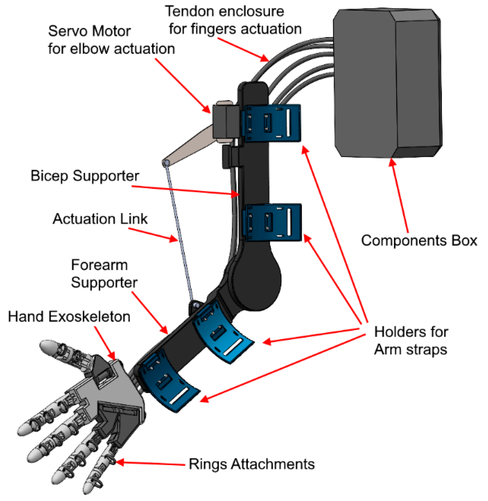
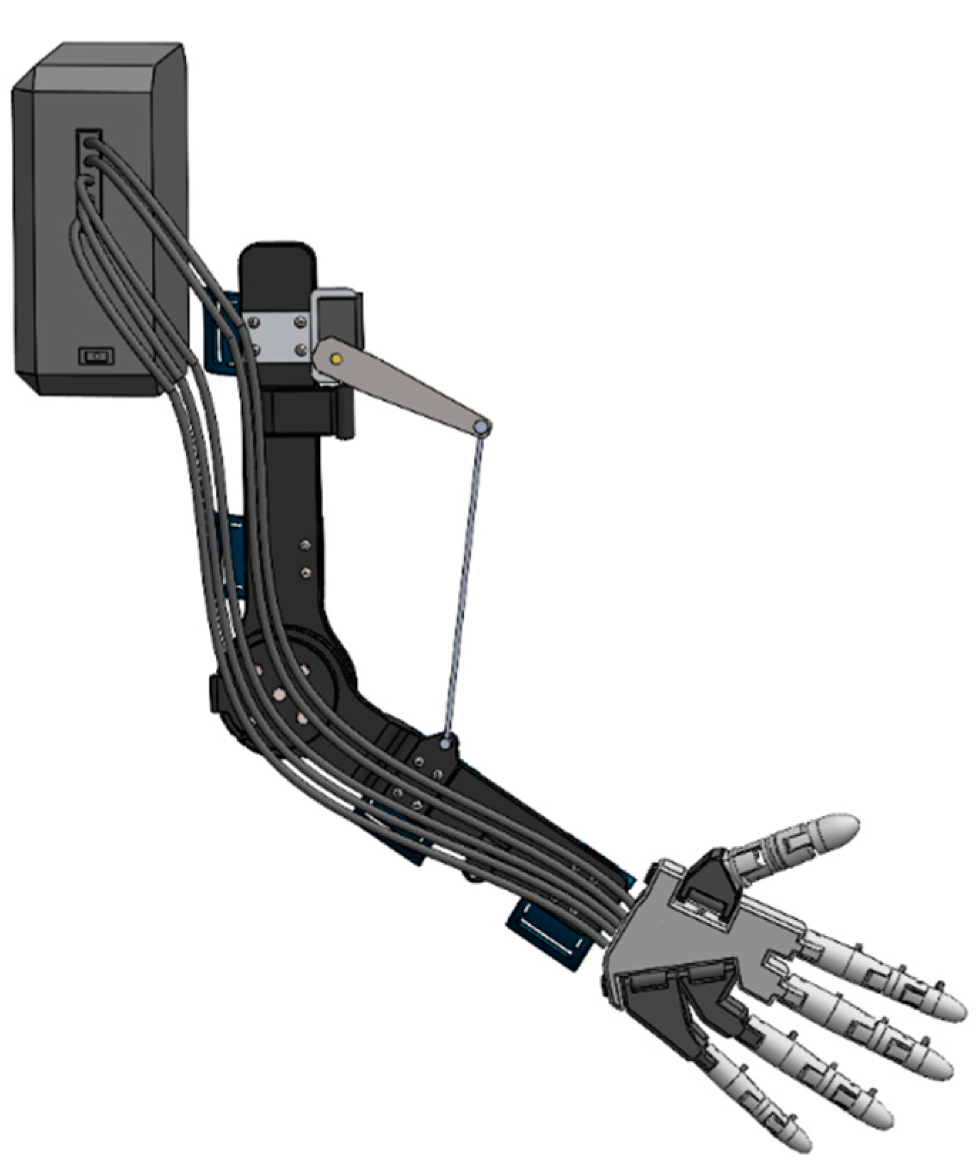
It is a difficult task to fulfill all of the requirements in an exoskeleton system, with the major difficulties being limited space and the trade-off between compactness, positioning accuracy, and weight, as well as the requirement of efficient and easy to maintain actuators. Firstly, the degrees of freedom of the human hand are high and there is very limited space for hardware to be installed. Hence, the actuators of the exoskeleton were placed in a backpack (components box) away from the hand and forearm, so there is no extra weight on the patient’s limb. After many revisions, the CAD model was developed, keeping in mind all the design constraints and improving the final design overall. The design of the exoskeleton is shown in the
Figure 8 and
Figure 9.
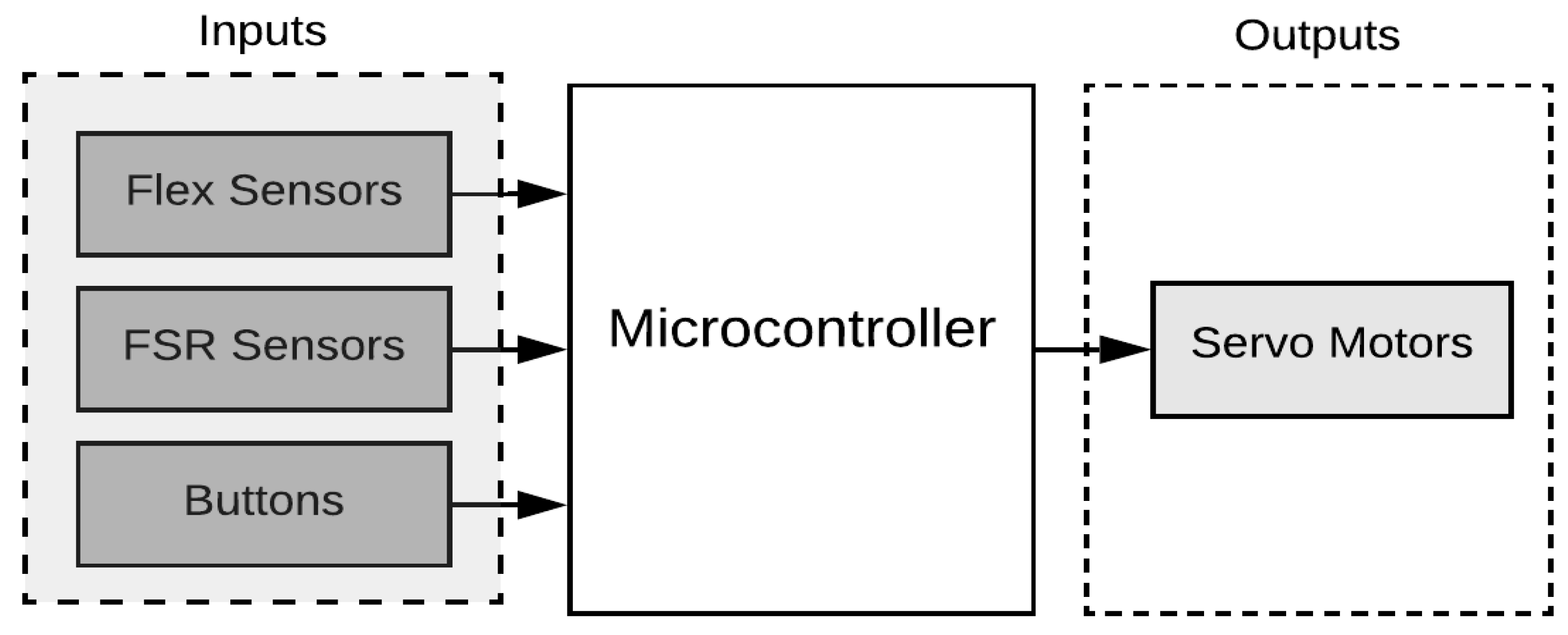
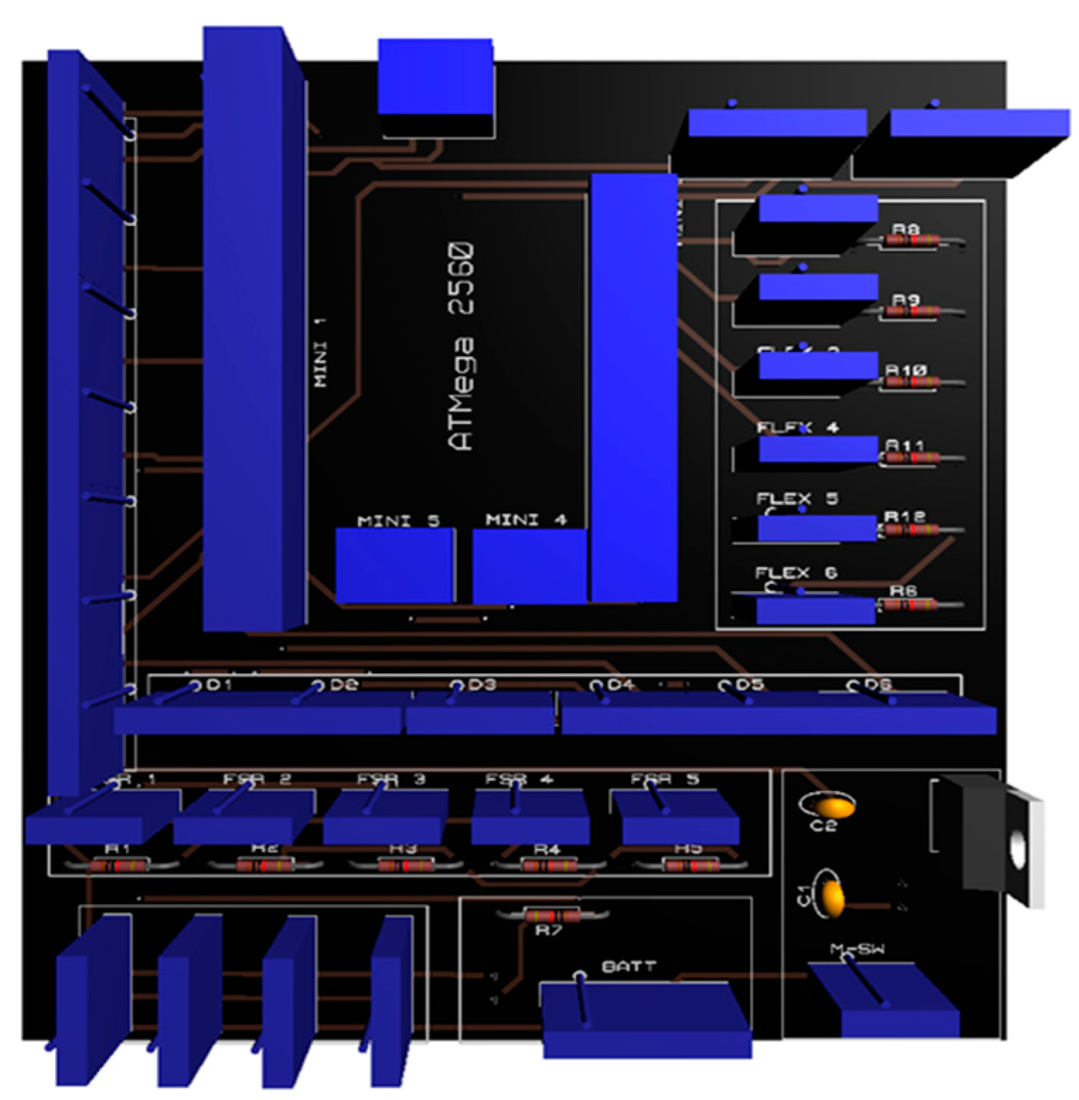
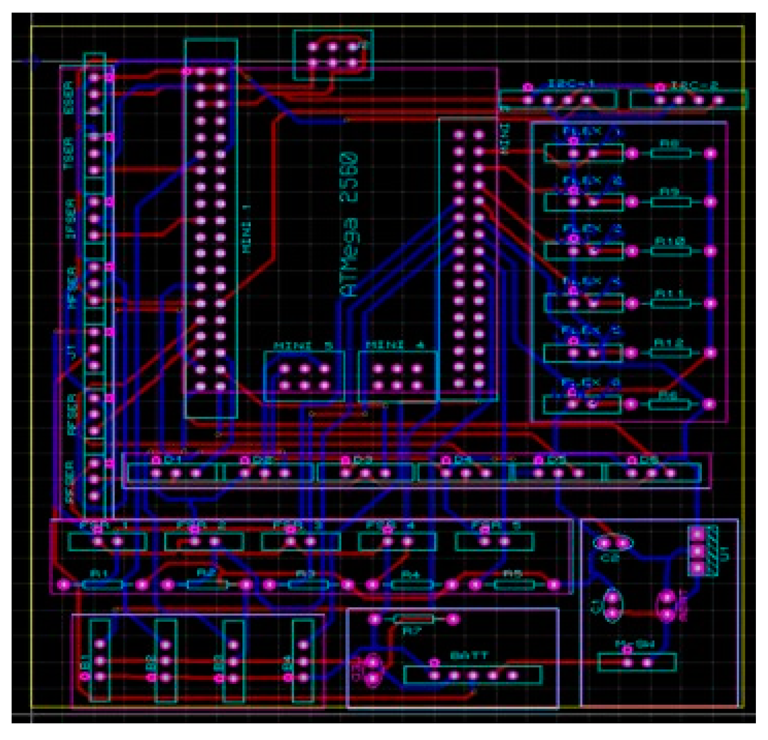
The exoskeleton’s design is divided into two parts, the hand exoskeleton and the arm exoskeleton. The hand exoskeleton is designed for the actuation of fingers; each finger is controlled by a separate servo motor, giving the advantage that each finger is controlled individually by the user. In total, five servo motors were incorporated into the design to control all five fingers of the hand exoskeleton. Ring-like attachments were included so that the user can easily wear the hand exoskeleton. For the actuation of the elbow joint, the arm exoskeleton was designed and only one servo motor is used for the actuation of the elbow joint. In this section, the electrical design of the exoskeleton is explained. The electrical design is divided into three parts. The first part is the microcontroller portion where the circuits were developed to integrate the sensors with the microcontroller. The second part is the battery and power connection, and the last part is the connections for the buttons to operate the exoskeleton. The Mega Pro Mini 2560 microcontroller was used for all the coding and the algorithm implementation. The microcontroller is mounted on top of the PCB, and all the sensors and the actuators are connected via the JST connectors. The PCB design is shown in the
Figure 10 and the 3D model of the PCB is depicted in
Figure 11. In
Figure 10, the blue blocks are the connectors for the actuators, buttons, and sensors.
3.1. Control Mechanism
In the exoskeleton, the PI controller implemented on the AT Mega 2560 is used to obtain the accurate and desired force, flex sensor and angle values for the exoskeleton. The aims were to control the force generated for gripping and augmentation purposes. When force is initially applied, the FSR sensor sends a signal to the microcontroller, which directs servos to move and achieve the desired value of force, as shown in
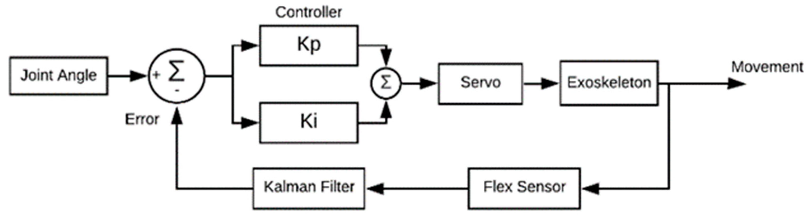
Figure 12. The proportional control (Kp) and integral constant (Ki) are most accurate for this case so that control runs well between input and output. The control loop repeats itself until the error becomes zero. Similarly, in the case of achieving the desired angle, the same control design is used for the exoskeleton, as shown in
Figure 13. The desired input angle is given as input and with a flex sensor value that directs the microcontroller, which in turn operates servos to obtain that input value. The error is subtracted and the setpoint value is achieved through the PI controller. In the case of a joint angle control algorithm, the Kalman filter is used, as shown in
Figure 13. The Kalman filter is an iterative mathematical process to quickly estimate the true value of an input. The data inputs we obtained consist of unpredictable random errors and uncertainty, which created a lot of difficulty for the system to obtain the exact/true value. Another way to reduce the noise and get close to the actual value is to take the average of the input, but this is a very slow process and not very accurate, which makes it hard for the system to determine the actual value. Due to this reason, we used the Kalman filter because it is faster and more accurate than other methods.
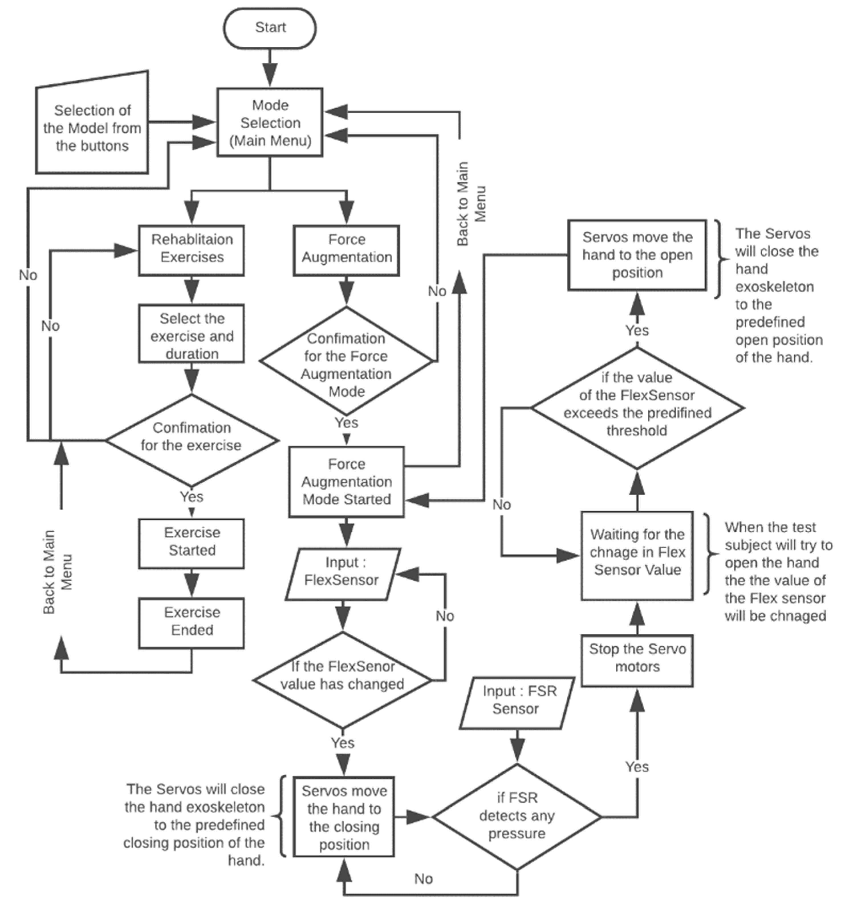
The programming was carried out on AT Mega 2560. The flow chart for the control algorithm is given in
Figure 14. The program starts with waiting for the user input for the selection of the mode. There are two modes programmed: force augmentation and rehabilitation. When the user selects a mode, confirmation is needed to start that mode. For example, when the force augmentation mode is selected, the program will wait for any increase in the value of the flex sensor. If the value has increased, the servo motors will start to close the hand exoskeleton and move until the preprogramed closing position. Meanwhile, the hand is closing. The FSR sensor placed at the tip of each finger detects if there is any object grasped by the user. If FSR detects any force feedback due to the wearer picking up an object, the servo motors will stop and wait for the user to open their hand. This mode stays in the loop until the user decides to end the mode or turn off the exoskeleton.
3.2. Sensors
The FSR (Force Sensing Resistor) was used to determine when the patient firmly grasped the object. For example, when the test subject tries to close their hand, the flex sensor will take the input and send the value to the microcontroller; then as an output, the servos will start to close the hand until there is a reading from the FSR. When the reading from the FSR is obtained, it means that now the object is firmly grasped and then the servos will stop. Later on, when the test subject tries to open their hand, the servos will move in the opening direction, and the hand opens.
3.2.1. Flex Sensor
The flex sensor is used measure the amount of deflection or bending. The sensor is usually placed on the surface, and when deflection occurs, it changes its resistance. Sensor resistance is proportional to the amount of bending, so it is also called a flexible potentiometer. Whenever the patient tries to move the hand to perform any task, the flex sensor will change its resistance and it will change its value up to the specified limit. After reaching that value, the flex sensor triggers a microcontroller that will then direct the servos accordingly. The spectra symbol makes the flex sensors to bend. They are coated on one side with a polymer with little conductive bits inside. When the sensor is flat (unbent), we measured the resistance to be 5.3 K Ohms and when the flex sensor was bent 20.5 K Ohms. FSR was used to determine when the patient has firmly grasped the object. For example, when the test subject will try to close its hand, the flex sensor will take the input and send the value to the microcontroller; then, as an output, the servos will start to close the hand until there is reading from the FSR. When we obtain the reading from the FSR, it means that now the object is firmly grasped and then the servos will stop. Later on, when the test subject will try to open the hand, the servos will move in the opening direction, and the hand opens at the angle of 0 degrees.
3.2.2. Force Sensing Resistor (FSR)
The FSR sensor detects force or pressure. Depending on how much force is applied, it changes its resistance. They are accurate and low cost. The FSR is comprised of two layers separated by a spacer. The more one applies force, the more of those active element dots make contact with the semiconductor, decreasing the resistance. The FSR sensors are developed by Winsen Electronics Technology Co., Ltd., Zhengzhou, China. based on new-type nanometer-sensitive, pressure-sensitive materials, supplemented by Young’s modulus and disposable pater ultrathin film substrate. It has functions that are both waterproof and pressure-sensitive. The sensor’s resistance value changes as the sensor detects external pressures. The sensor we use is DF9-40 @1Kg, this sensor is chosen because it fits our specifications, as we do not need to use more force to pick up an item weighing 1 kg. The FSR is calibrated to remove errors. These errors arise due to some structural flaws in the sensor outputs. To achieve the best possible accuracy, a sensor should be calibrated in the system where it will be used. Thus, the FSR was calibrated to achieve the best possible results, as it does not give accurate results before calibration.
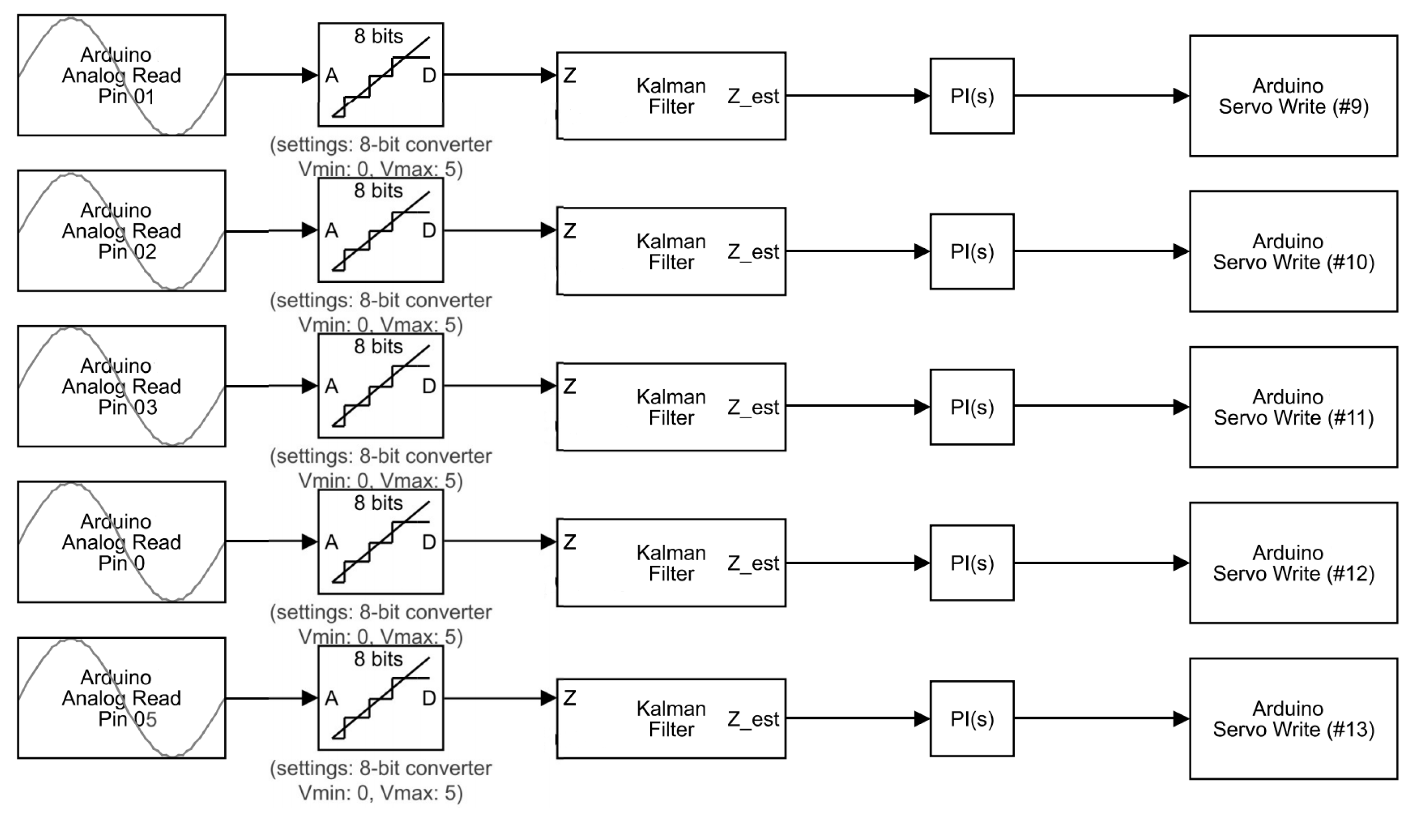
3.3. Control Algorithm
The data is acquired as input from the flex sensor, which is an analog signal. This signal then goes to a digital converter (ADC) analog, which transforms this analog signal into a digital signal. Arduino has an 8-bit ADC, which means 1024 discrete analog levels are detected. In this way, the analog signal coming from 0 to 5 volts is converted into 1024 discrete levels through ADC. This signal goes through the Kalman filter, which removes the noise and filter signal. The sample rate of the Kalman filter is set to 1 s. The Kalman filter is an iterative mathematical method for the rapid calculation of an input’s true value. The data inputs that we received consist of unpredicted random errors and uncertainty that generated a lot of difficulty in obtaining the exact/true value for the method. The Kalman filter helps us to predict and determine values that are very close to the actual value. The control parameters P and I determine the desired output. By setting the gain, we obtain the desired angle of the exoskeleton. The control algorithm of the flex sensors implemented on Mega Pro is shown in
Figure 15.
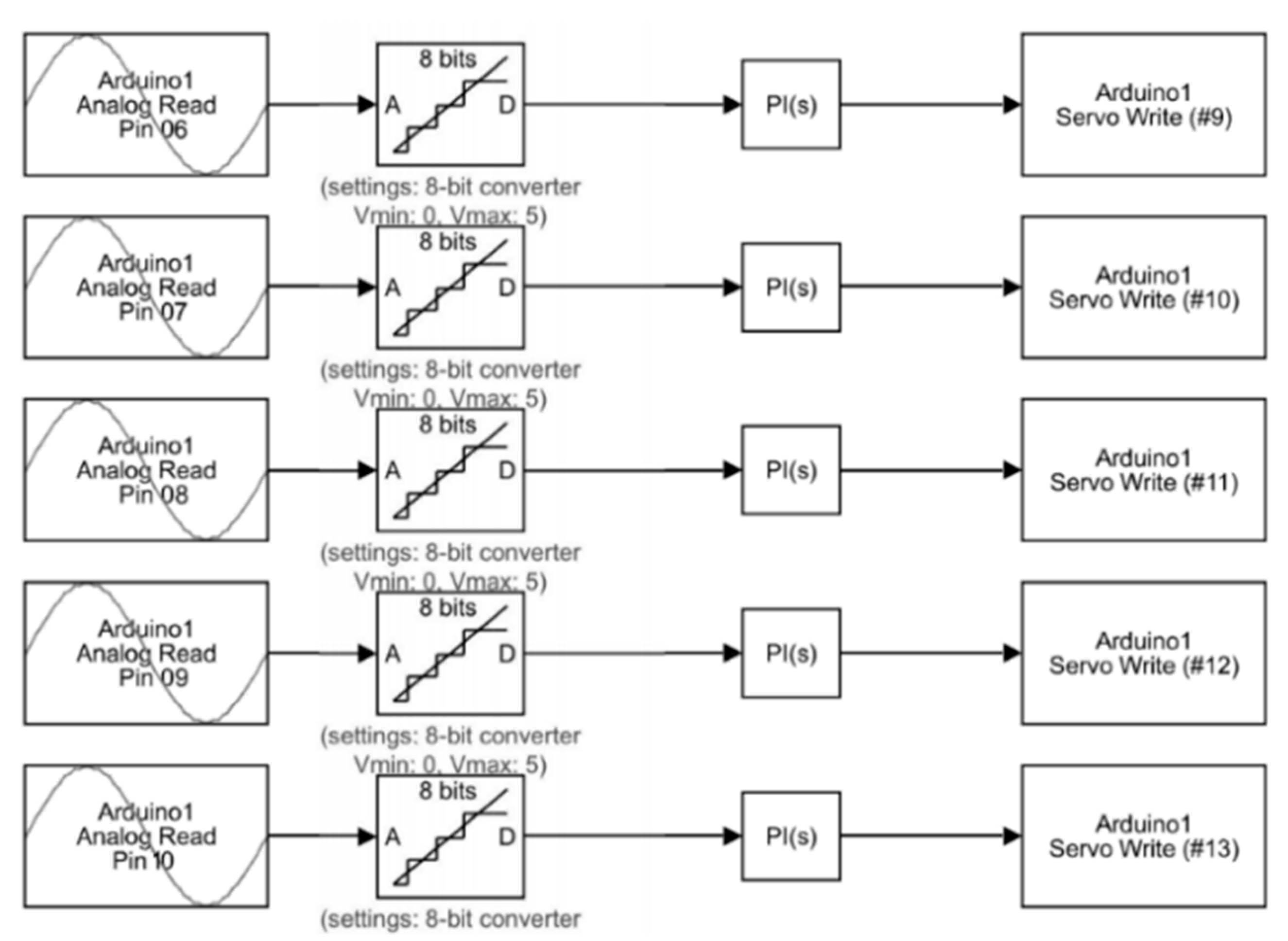
The control algorithm implementation of the FSR sensor is shown in
Figure 16. The FSR sensor is sending an analog signal to a microcontroller. The analog-to-digital converter on the microcontroller converts this analog signal into digital one. It has an eight-bit ADC which converts 0 to 5 volts of analog signal of FSR to 1024 discrete analog levels. In this process, we do not need any filter, as it works fine without one. The PI controller then sets the desired output for the plant. By changing the values of gains P and I, the exoskeleton gets the desired value of force. It then directs the actuator to move with desired output values.
4. Results and Discussion
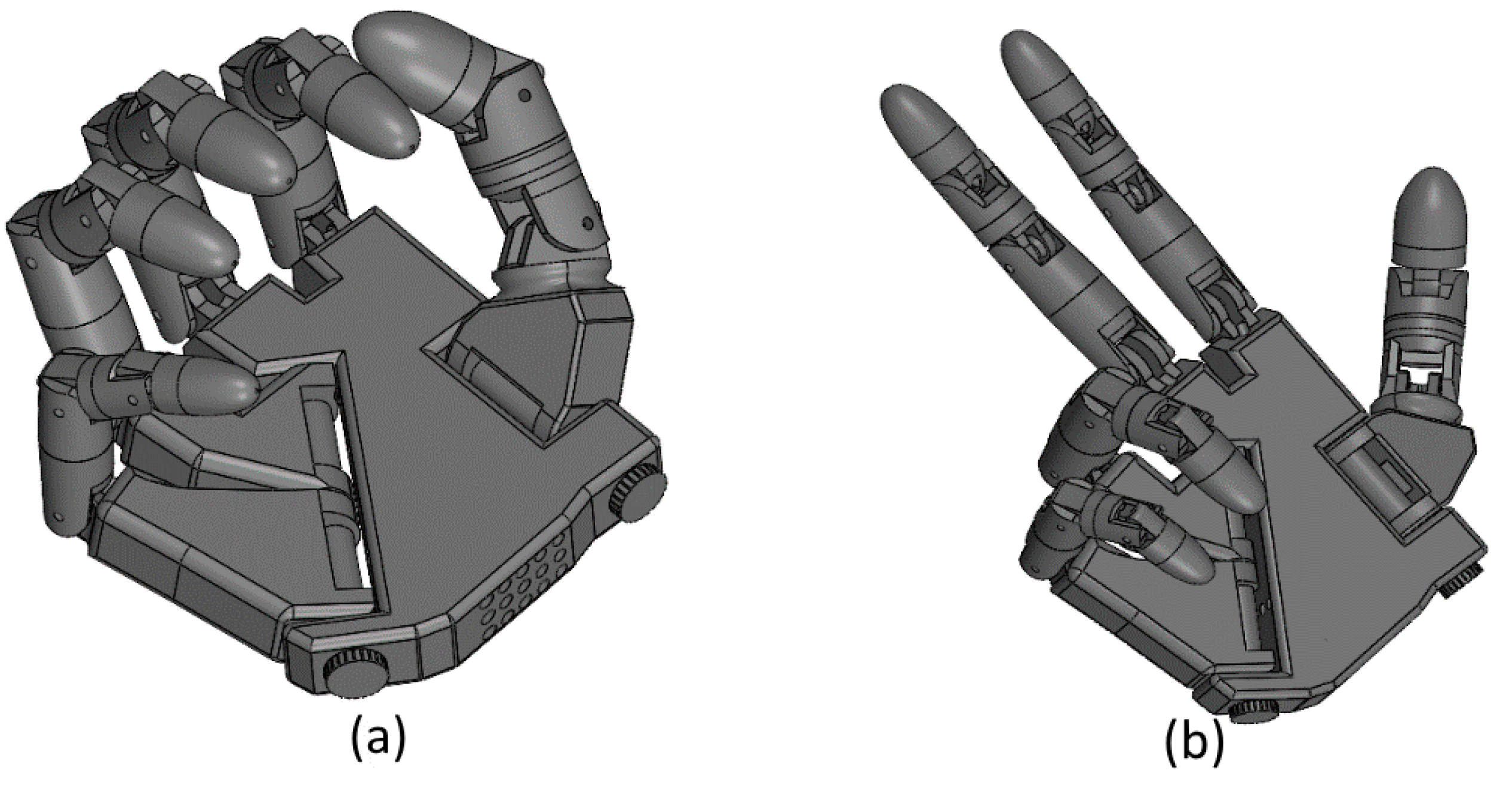
Prior to the development of the presented exoskeleton, the model was tested in simulation. Motion analysis was performed on SOLIDWORKS
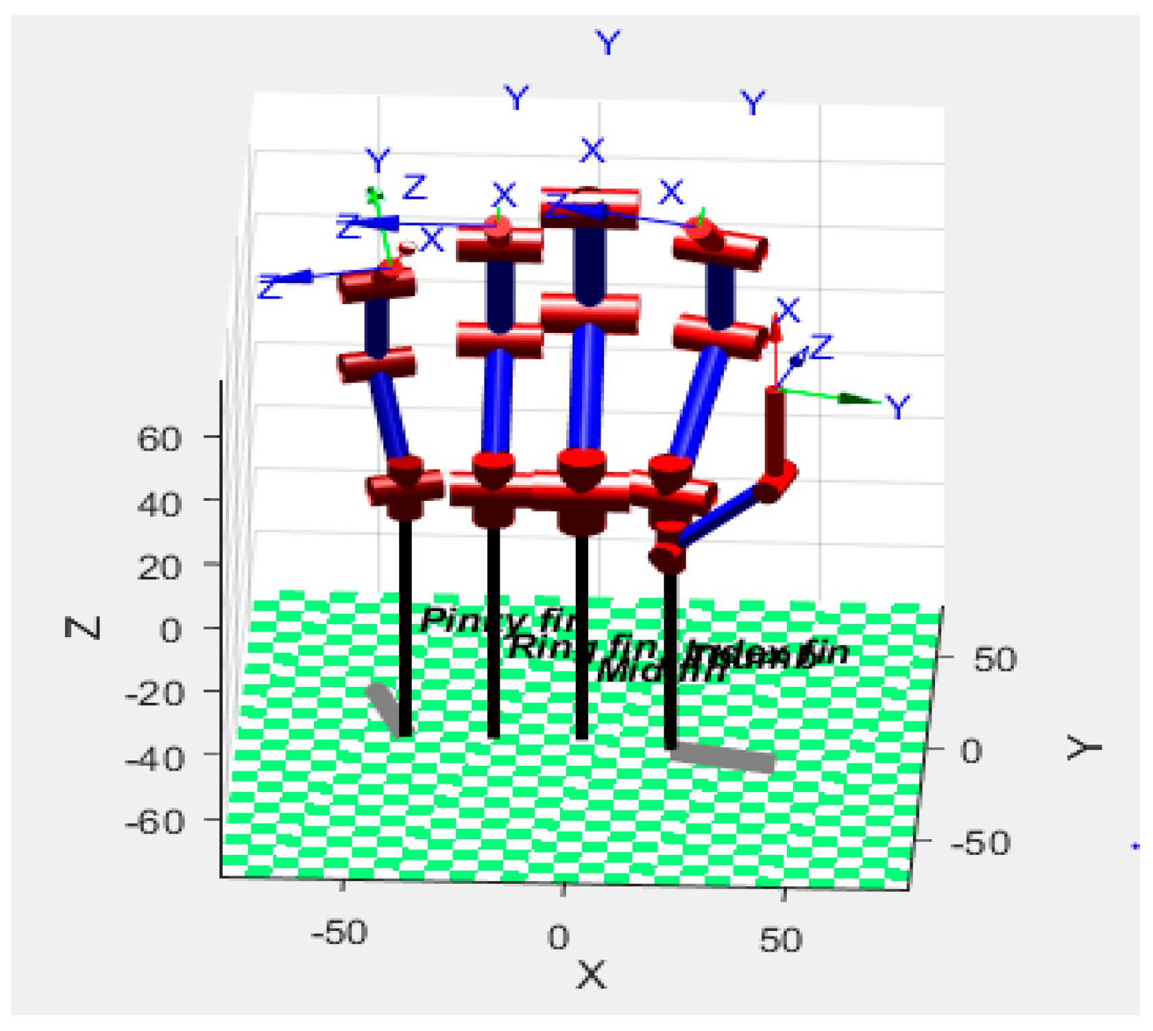
® for both the hand and arm exoskeleton in order to test the design for its functionality and range of motion. Selected experiments of motion study for grip (hand closed) and victory gestures were performed. In
Figure 17a, the closed position of the hand exoskeleton is shown and in
Figure 17b the victory gesture is made from the hand exoskeleton to demonstrate the ability to have individual finger control. In
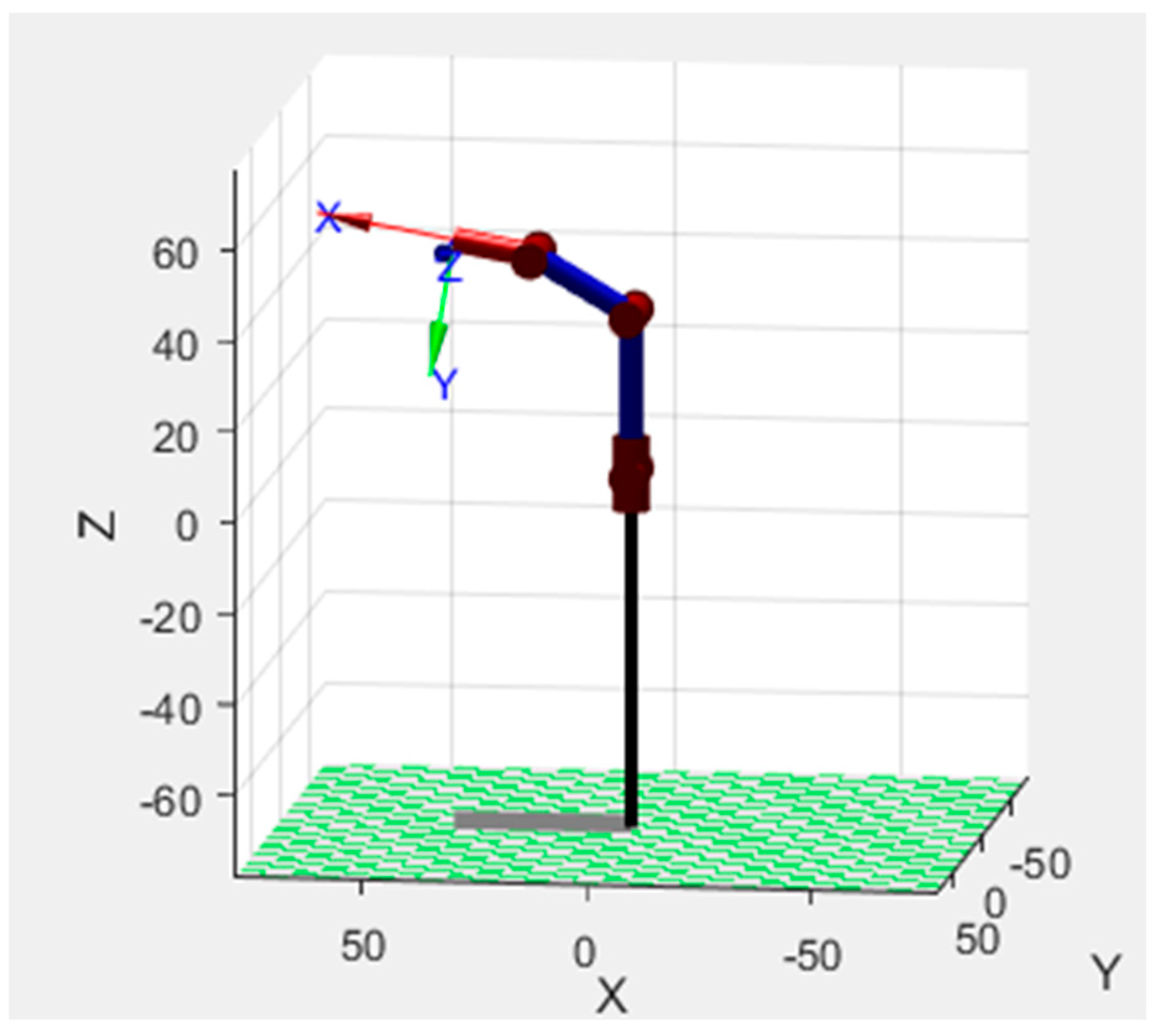
Figure 18, the motion analysis of the arm exoskeleton is shown.
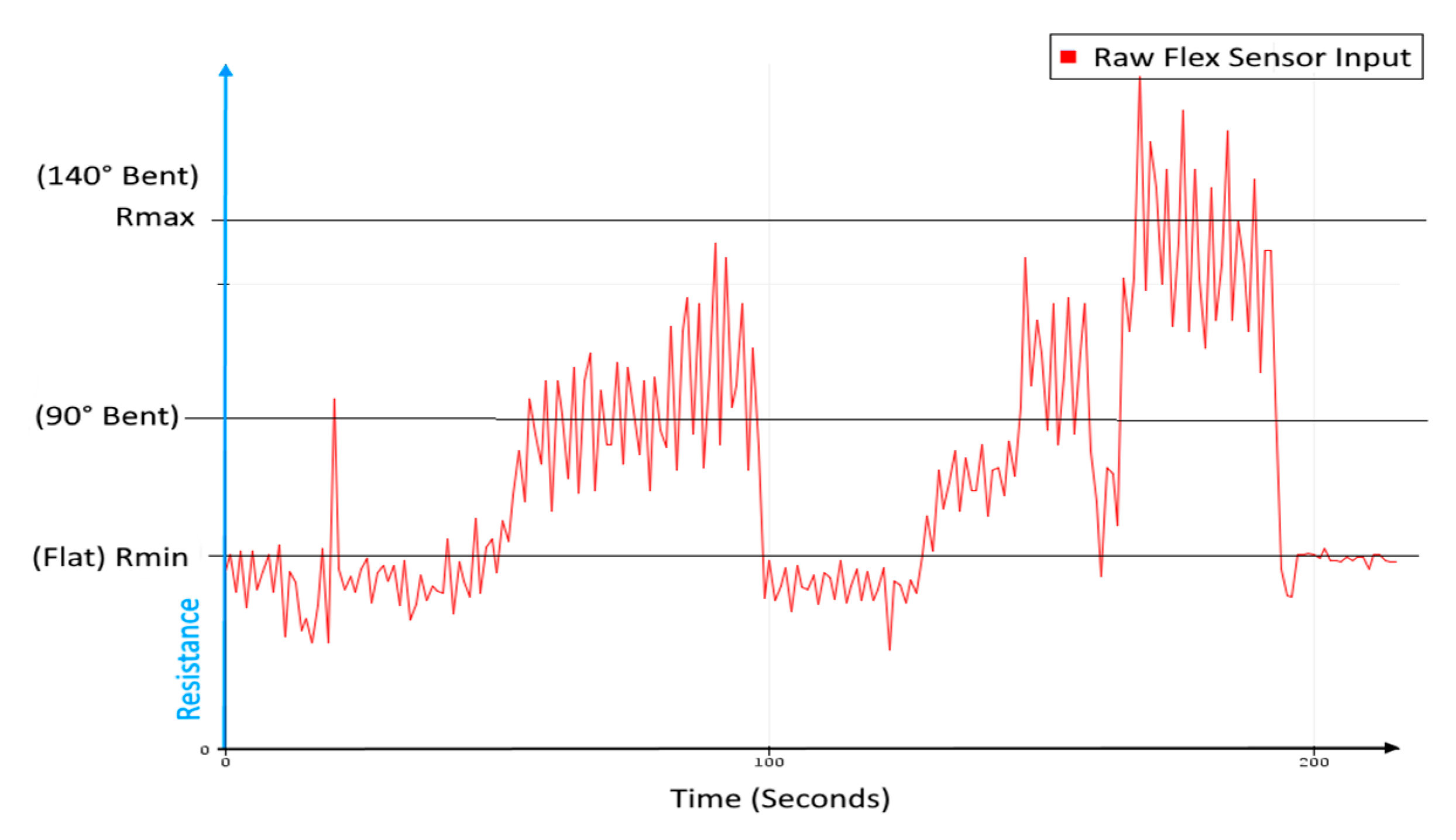
In order to acquire portability advantage of the proposed model of the exoskeleton, it was manufactured using 3D printing. The 3D printing made the exoskeleton cost effective and easy to manufacture. Prior to experiments for motion study on the hardware, the hardware and the algorithm were tested. The input from the flex sensor was non-uniform and quite noisy, so to overcome that problem, the Kalman filter was used. In
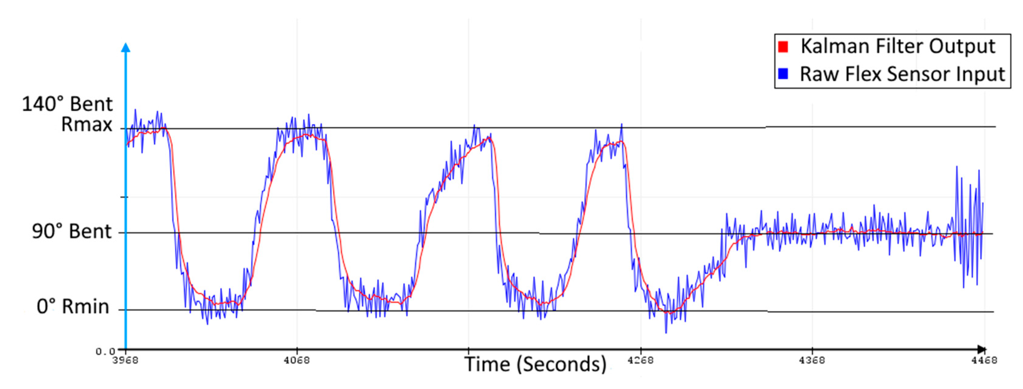
Figure 19, the raw signal from the flex sensor is shown. The raw signal shows the relationship between the change in resistance and the change in position (bent angle) with time. The raw signal is communicated to the microcontroller. A continuous signal variation due to noise is not acceptable for the control algorithm as it will demand high input energy. Hence, the Kalman filter is used. In
Figure 20, the Kalman filter is applied on the raw input from the flex sensor, making it smooth output for the actuation loop for the servo motors. Experiments for hand and elbow joint motion were performed to evaluate the effectiveness of the proposed exoskeleton. In the experiments, the participant was healthy and they were advised to apply little to no movement and force in order to test the capabilities of the exoskeleton for a monoparesis patient.
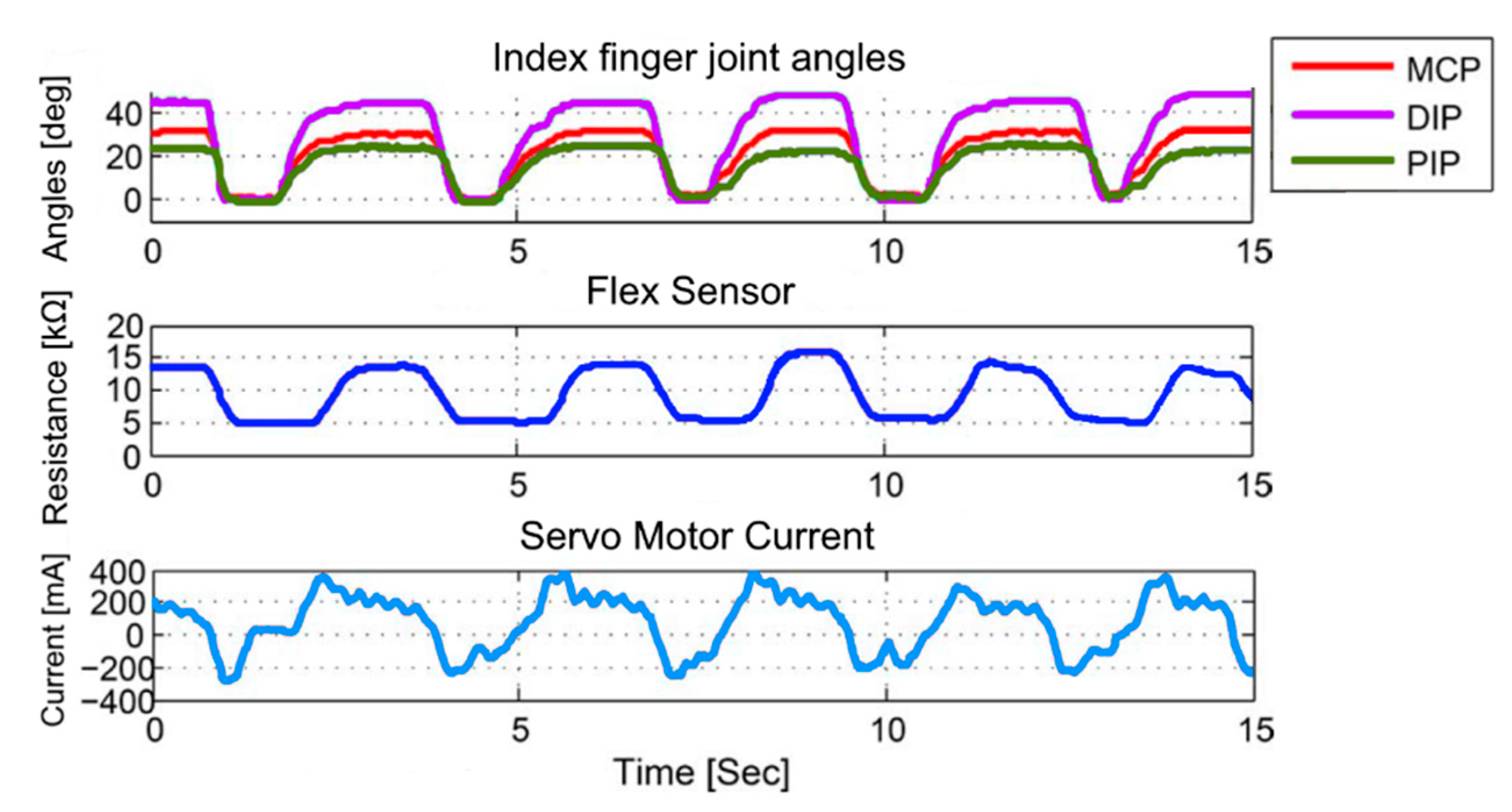
The first experiment was to record the motion of the hand’s fingers in a picking up and placing task. The task includes the procedure of picking up, lifting, holding, and releasing. A bottle of water was used in this experiment. In the experiment, the hand exoskeleton was controlled to follow the movement of the user’s hand with the help of flex sensors providing support and grip to the user’s hand. After getting used to wearing the exoskeleton, the participant was asked to perform the task five times for about 15 s, for a demonstrative example of the test results. The output motion of the index finger is shown along with the flex sensor input in
Figure 21. MCP (Meta Carpo Phalangeal), DIP (Distal Inter Phalangeal), and PIP (Proximal Inter Phalangeal) are the three joints of the index finger.
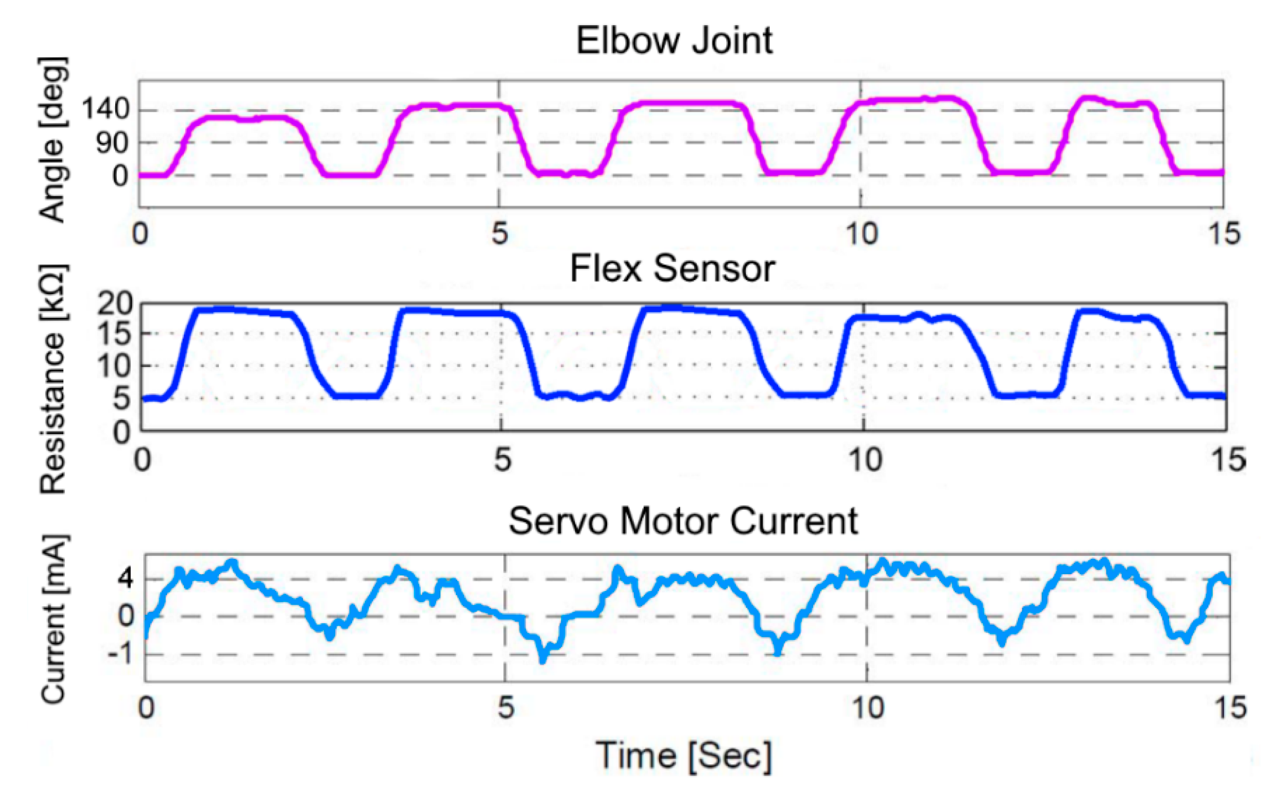
The second experiment was to record the motion of the elbow joint in a flexion and extension task. The task includes the flexion and extension of the elbow joint while wearing the exoskeleton. In the experiment, the forearm exoskeleton was controlled to follow the movement of the user’s elbow joint to provide support and strength. In this experiment, the participant was asked to perform the flexion and extension task five times in 15 s for the demonstration of test results. The output motion of the elbow joint and the flex sensor input is shown in
Figure 22.
The experiments showed that the motion of the finger joints of the hand exoskeleton proved to be satisfactory, with minor room for improvement in the control algorithm. However, the motion of the forearm exoskeleton is accurate. While designing the arm exoskeleton, it was kept in mind that it should have a range of motion of 140°, which is the range of motion of the elbow joint of an adult [
25]. The 140° range of motion of the arm exoskeleton is also validated in the experiment. The structure of the hand exoskeleton can be designed to be more ergonomic to further enhance the comfort for the user.


 ,
, 


