1. Introduction
A transformer plays a vital role in energy conversion and is at the heart of the electric power system. The transformer size decreases with increasing frequency, which allows for the building of smaller, less expensive, and compact portable electrical devices [
1,
2]. Therefore, high frequency power transformers are preferred over traditional frequency transformers (50–60 Hz) in the power electronic fields, such as switching power supplies; converters; and inverters, including medium voltage (MV) inverters, which offer a step-up transformer-less solution to interconnect photovoltaic (PV) arrays to the MV grid [
3,
4,
5,
6,
7,
8].
Green energy is a priority of many researchers because of population and industrial growth, which are leading the world towards an extensive rise of global warming threats and visible climate change. Therefore, renewable energy sources are in high demand, particularly solar and wind energy. These sources are projected to fulfill 50% of the energy requirement by the year 2050 [
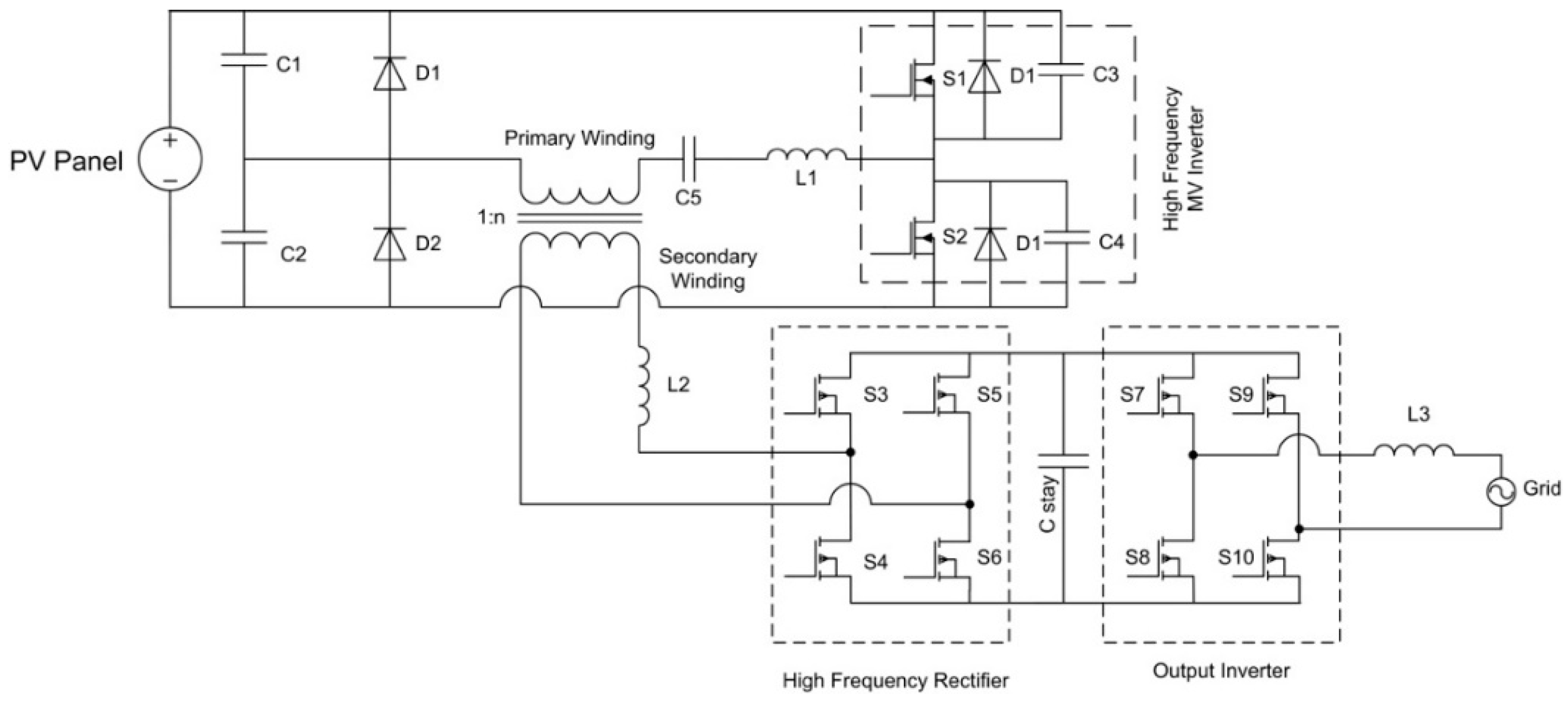
9]. On the other hand, the intermittent nature of these power sources is a major limitation to connecting them straight to electrical/electronic systems or national grids. This critical obstacle can be overcome using external devices, such as energy storage, converters, and inverters (see
Figure 1) [
10,
11,
12,
13]. As a result of the high penetration of these high-frequency-based MV inverters into the renewable energy power plants, energy demands could be fulfilled for industries and home power requirements. However, these high-frequency links, for example, high-frequency transformer, H-bridge inverter dead time, and non-linear load, generates high harmonic content. This can cause serious damage to the equipment including overheating, power supply failure, or electric shock hazards [
14,
15]. Consequently, to protect the component and the connected loads from overheating and to provide a power supply without any disturbances, the power quality of these MV inverters needs to be taken into consideration [
16,
17,
18,
19].
An electromagnetic interference (EMI) in inverters can affect the power quality of transients, both short time and longtime deviation, which can cause harmonics. In these devices, harmonics can be categorized into two classes: common and differential conduction modes (CCM and DCM) [
20,
21,
22]. The high-frequency transformer is one of the sources of EMI and contributes to the common mode harmonics because of the intrinsic coupling capacitance, and electric and magnetic fields [
23]. The duty cycle is inversely proportional to the harmonics. Therefore, DCM operations of pulse-width modulation (PWM) converters increase the harmonics, which adds power losses in transformer windings. Similarly, high-frequency operation causes skin and proximity effects that elevate the harmonic losses, winding power losses, and rapid growth in the operating temperature [
24,
25]. On the other hand, high frequency winding losses and lowering the leakage inductance has been a major research focus, while the winding capacitance requires equally serious attention during the design of transformers. Capacitive coupling is one of the paths that can carry high frequency noise; premature resonance; electrostatic coupling to other circuits; and fast transient voltages from primary to secondary circuitry, which produces common mode noise currents and an increase in transformer temperature in the device, resulting in a deterioration of the overall system operation, noise, health, and safety threats.
This capacitive coupling is an eruption effect of a transformer parasitic, rooted by a wide range of capacitance across the transformer, which circulates as a result of winding arrangements. Therefore, the key to overcoming this critical hurdle is lowering the inter-winding capacitance. Conventional methods to reduce the emergence of capacitive coupling at the transformer include increasing the insulation between the primary and secondary winding or increasing the distance between the primary and secondary winding by winding them on opposite sides of the toroidal core. These changes in the transformer will, however, cause other drawbacks, such as high leakage inductance, larger physical size, and poor inductive coupling. Accordingly, conventional methods are not completely effective in improving the power quality. On the other hand, previous studies [
26,
27,
28,
29,
30,
31,
32] examined the techniques on smart transformers fuzzy logic based transformers by winding using fiber optic sensors and certain oils for cooling the transformer. They, however, were arranged specifically for the coupling capacitance and temperature control and showed no significant difference when compared with the less expensive conventional solutions.
The leakage inductance and primary/secondary capacitance are mutually exclusive and are governed by the distance between the windings and the unwounded core. As a result of this, it is difficult to achieve both low capacitive coupling and a high degree of inductive coupling in a power transformer [
33,
34]. To circumvent this inherent tradeoff in this study, the conventional toroid ferrite core transformer was modified by an additional 3D printed polylactic acid (PLA) mold, which separates the primary and secondary windings, and helps to implement unique sector winding. Although the distance between windings will introduce leakage inductance, there is some gain in capacitance due to the dielectric constant of PLA. However, the magnetic core geometry and winding arrangements have a large influence on self-capacitance and leakage inductance of the transformer and because of the addition of a mold, it enables access to various types of winding arrangements. This paper reports a comparative analysis on the high frequency-link MV inverter for power-quality improvement by effective subtraction of capacitive coupling and reducing the temperature increase without using any extra circuitry or cooling agents.
4. Calculation of the Transformer Inter-Winding Capacitance
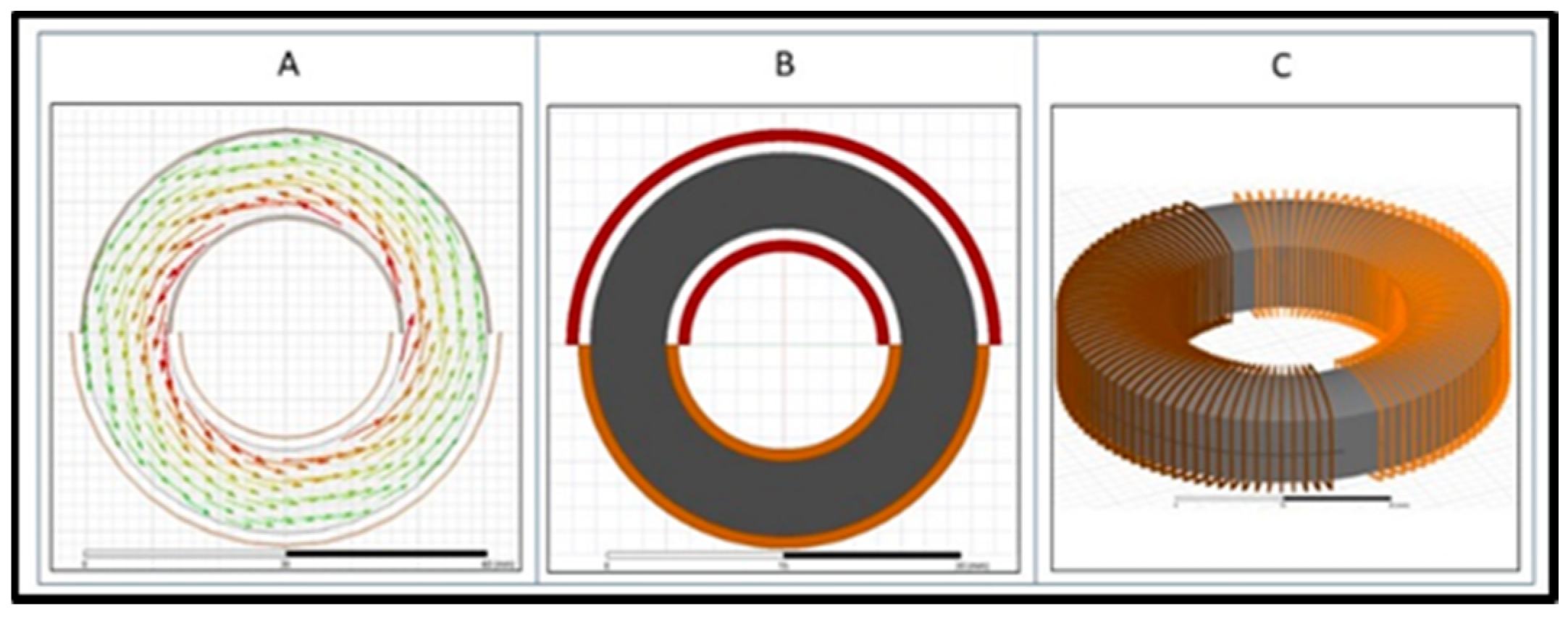
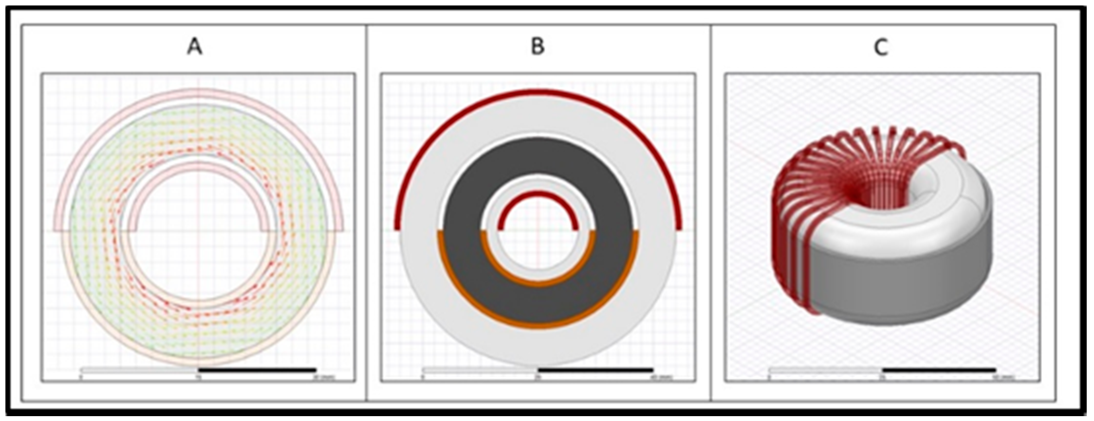
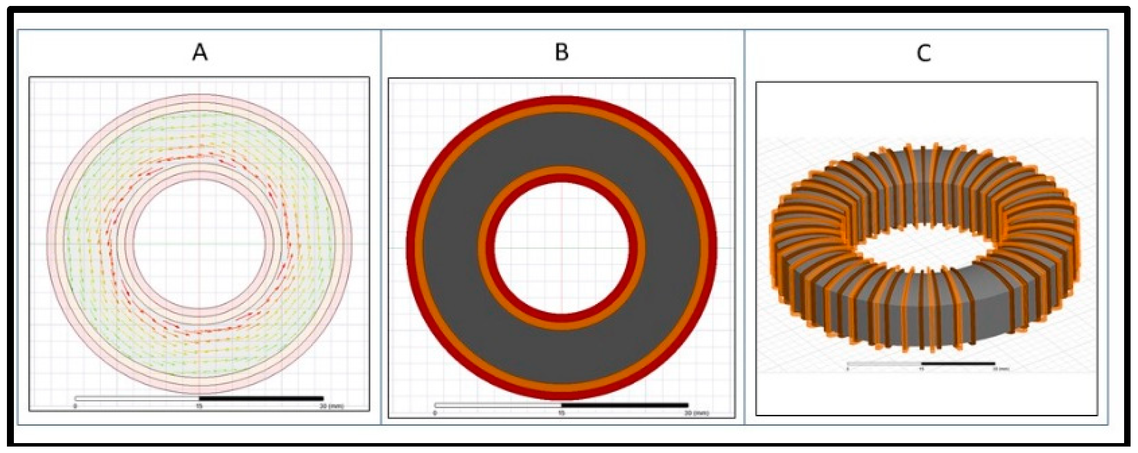
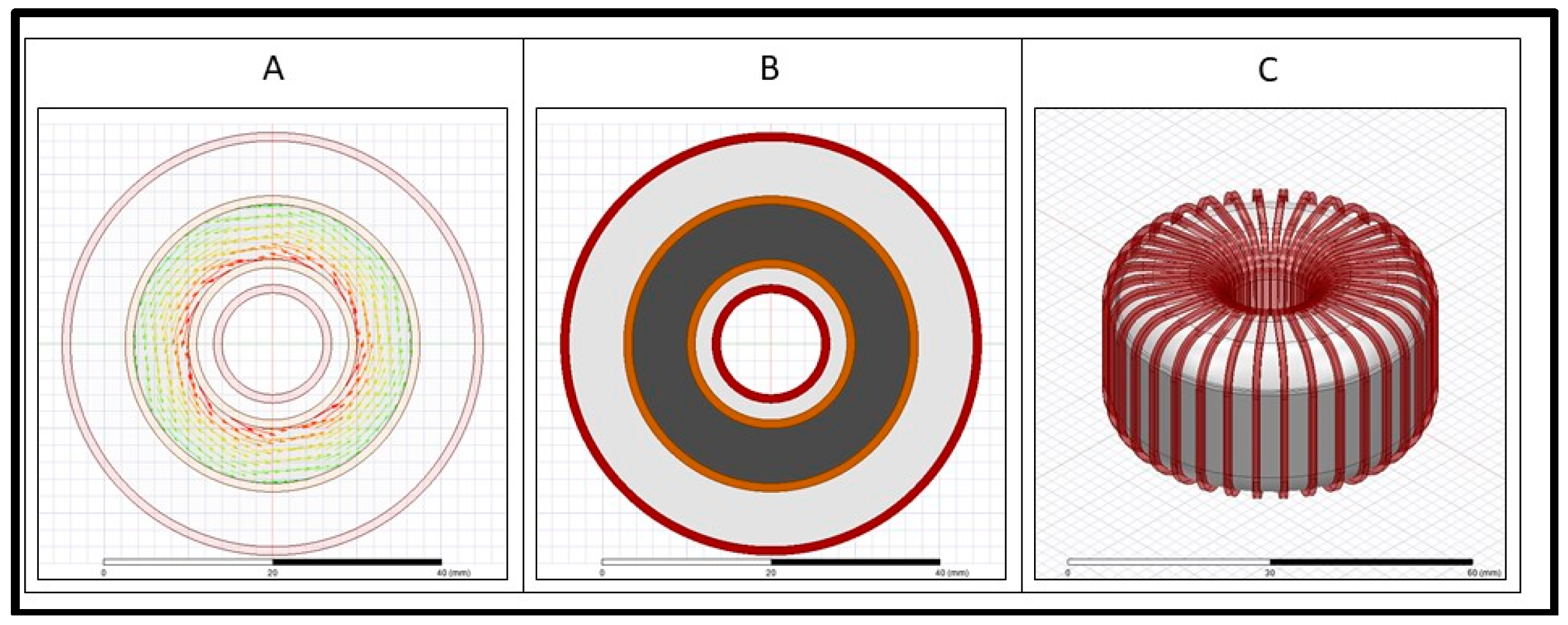
The general structure (2D, 3D, and flux flow in core) of the four designed transformer’s prototypes under test are illustrated in the fabrication section (3). In this section, prototype transformer calculations were carried out for inter-winding capacitance.
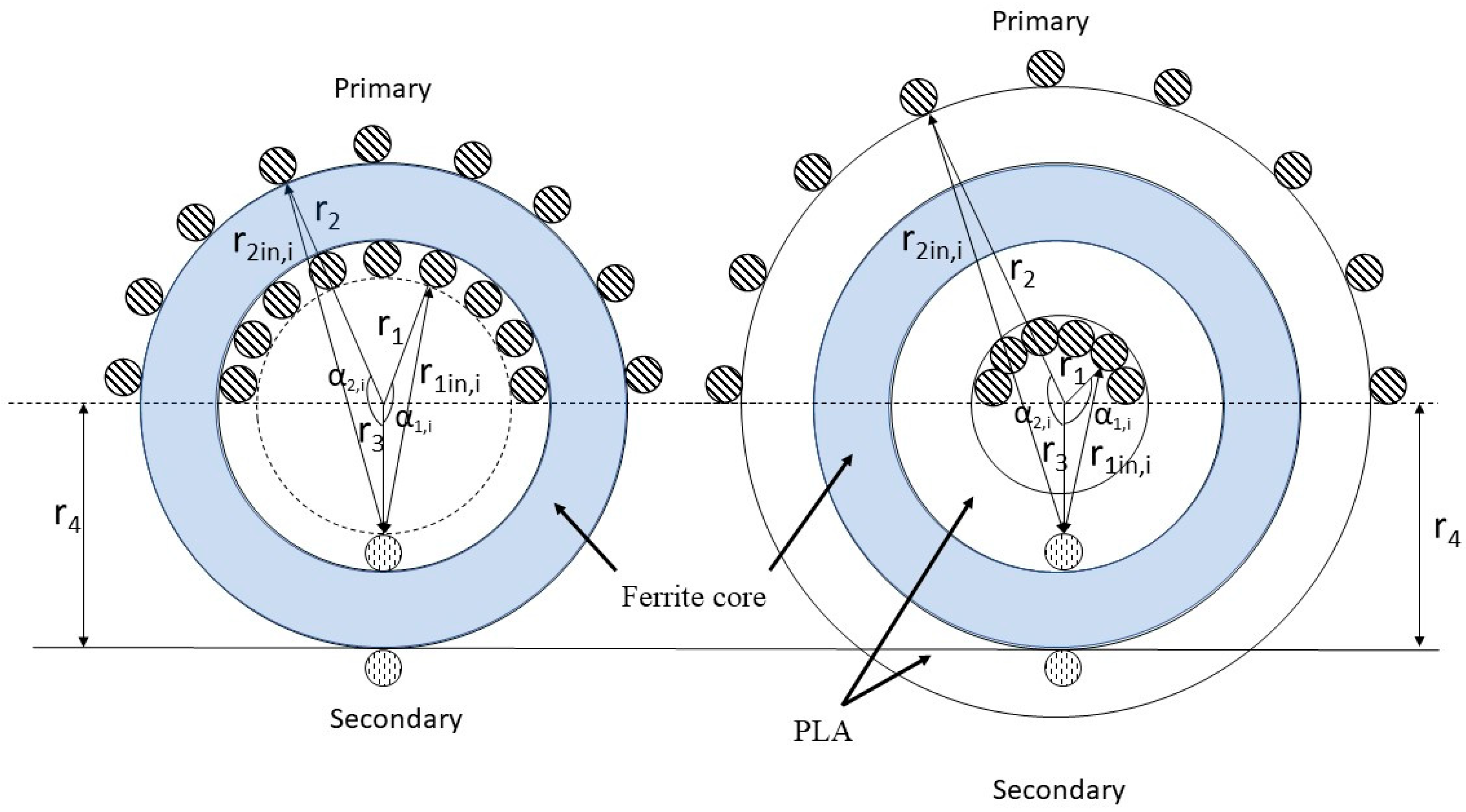
Figure 9 shows the conceptual structure of case 1 and case 2 transformer prototypes for inter-winding capacitance calculation. Likewise, the capacitance for other prototypes can be evaluated in a similar manner.
Ferrite core material 77 has a negligible effect on parasitic capacitance; therefore, only winding configurations were taken into account. For the sake of simplicity, only one winding of the secondary side, which is wound on the ferrite core, is considered for calculation of inter-winding capacitance. The same position of the secondary winding is considered for all four cases.
The distance between the inner secondary winding and inner primary windings can be expressed as follows:
where
r1 is the distance from the center of the core to the inner primary windings,
r2 is the distance from the center of the core to the outer primary windings,
r3 is the distance from the center of the core to the inner secondary windings,
r4 is the distance from the center of the core to the outer secondary windings (
Figure 9), and
np is the total number of primary turns. In all four cases,
and
values are the same, as secondary winding is wounded on the ferrite core and core dimension is same for all transformer prototypes. On the other hand,
and
values will vary with respect to each case, for example,
, for case 4 (
) and case 2 (
) will be same, but they are less than case 3 (
), which in turn is less than case 1 (
). The details of
,
,
,
for the four different configurations are given as follows:
The static capacitance between the inner primary and inner secondary is as follows:
where Є∘ is the permittivity of free space,
d is the diameter of the wire used for primary and secondary windings, and
l1 is the overlapped length.
Assuming that the voltage potential distribution along the primary turn varies linearly,
The total stored energy between the inner primary and secondary is as follows:
Similarly, the capacitance between the inner primary–outer secondary, outer primary–outer secondary, and outer primary–outer secondary can be calculated. Equations (4)–(7) can be used to find the capacitance and energy for the other three cases as well (
Table 4). The simulation was run on MATLAB to calculate the capacitance in all four cases. For the sake of simplicity and to ignore the repetitive process of inter-winding capacitance calculations, only one winding in the same position of the secondary side is considered for all four cases. To see the effect of inter-winding capacitance, we choose three primary winding for 180° conventional and modified configurations instead of 116, and 6 primary windings for 360° conventional and modified configurations instead of 220.
It can be seen from
Table 5 that the inter-winding capacitance would be highest for case 3, followed by that for case 1, case 4, and case 2. These analytical calculations hold well with the experimental data for inter-winding capacitance, which is shown in the next section.
5. Experimental Setup
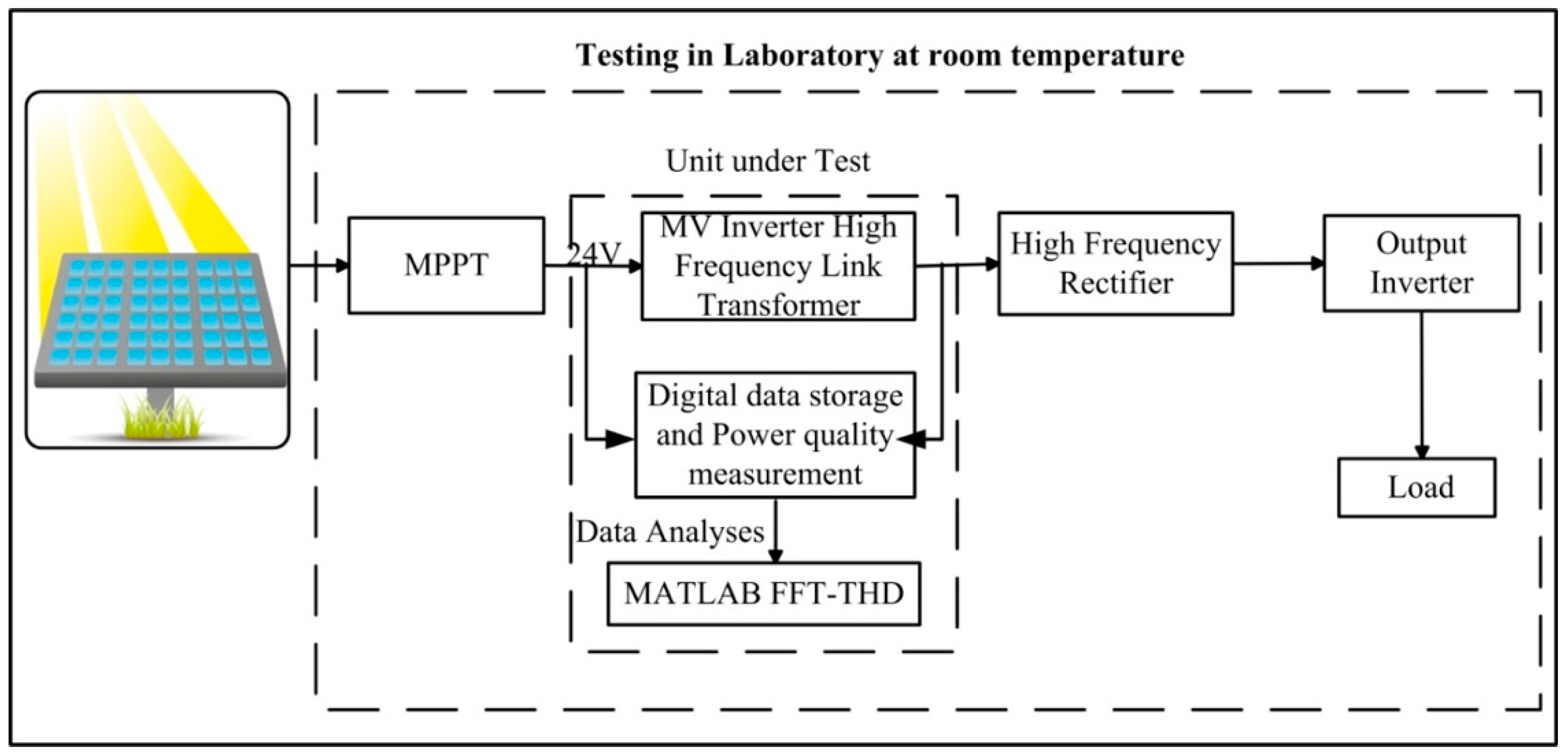
The high-frequency transformer temperature, capacitive coupling, and leakage inductance were measured using a Fluke VT04A (Fluke, Everett, WA, USA) Thermometer and GWInstek LCR (GWINSTEK, New Taipei City, Tucheng Dist., Taiwan) meter. The experiments were conducted at constant ambient room temperature, on the high-frequency link of a 1 kW half bridge MV inverter. Two 38 V, 350 W standalone solar modules connected in parallel served as input for the developed inverter. Owing to the addition of a 3D printed mold and sector winding, it was possible to have different winding arrangements. A number of modified toroid high-frequency transformers have been developed with different sector windings, such as 45°, 90°, 120°, 180°, 270°, and 360°.
Figure 10 presents a block diagram of the experimental setup. The input and output waveforms of the transformer were stored, and the harmonic contents present in the waveform were analyzed by Matlab-FFT (MathWorks, Natick, MA, USA).
6. Results and Discussion
For the comparative analysis, we designed a conventional toroid transformer with the same 180° and 360° sector windings and the same core dimension. The comparative experimental studies stated that the proposed modified design succeeded in lowering the inter-winding capacitance (approximately 87%) and controlling temperature increase issues (less than 30°) when compared with conventional designs; detailed discussion based on sectored winding is shown below.
Table 6 compares the THD of the aforementioned transformer prototypes. By comparative analysis of normative
Table 3 and experimental result
Table 6, it is clearly visible that all the prototypes have a minimum risk. Although, modified designs have registered more or less similar distortion compared with conventional designs.
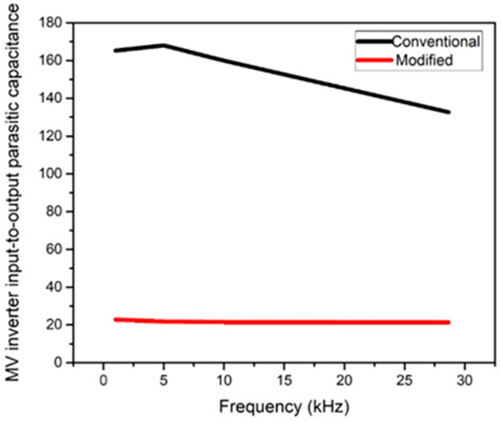
6.1. Toroidal Transformer with 180° Sectored Winding
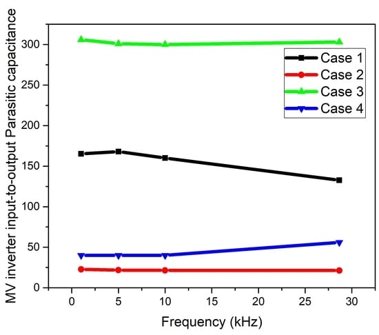
Inter-winding Capacitance: Large inter-winding capacitance causes a significant amount of common mode noise at high-frequency operations.
Figure 11 shows the comparison for parasitic capacitance from 1 to 30 kHz frequency at a high-frequency-based MV inverter. It is clearly visible that the proposed modified design has minimized the parasitic capacitance close to 20 pF, which is much lower than the conventional design. This was because of the mold, which helped increase the distance between the windings.
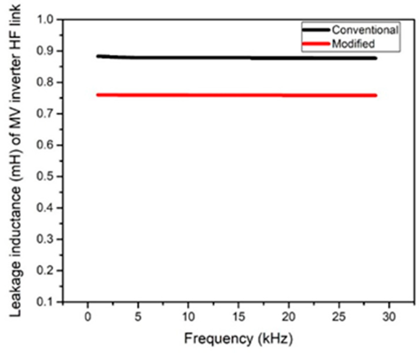
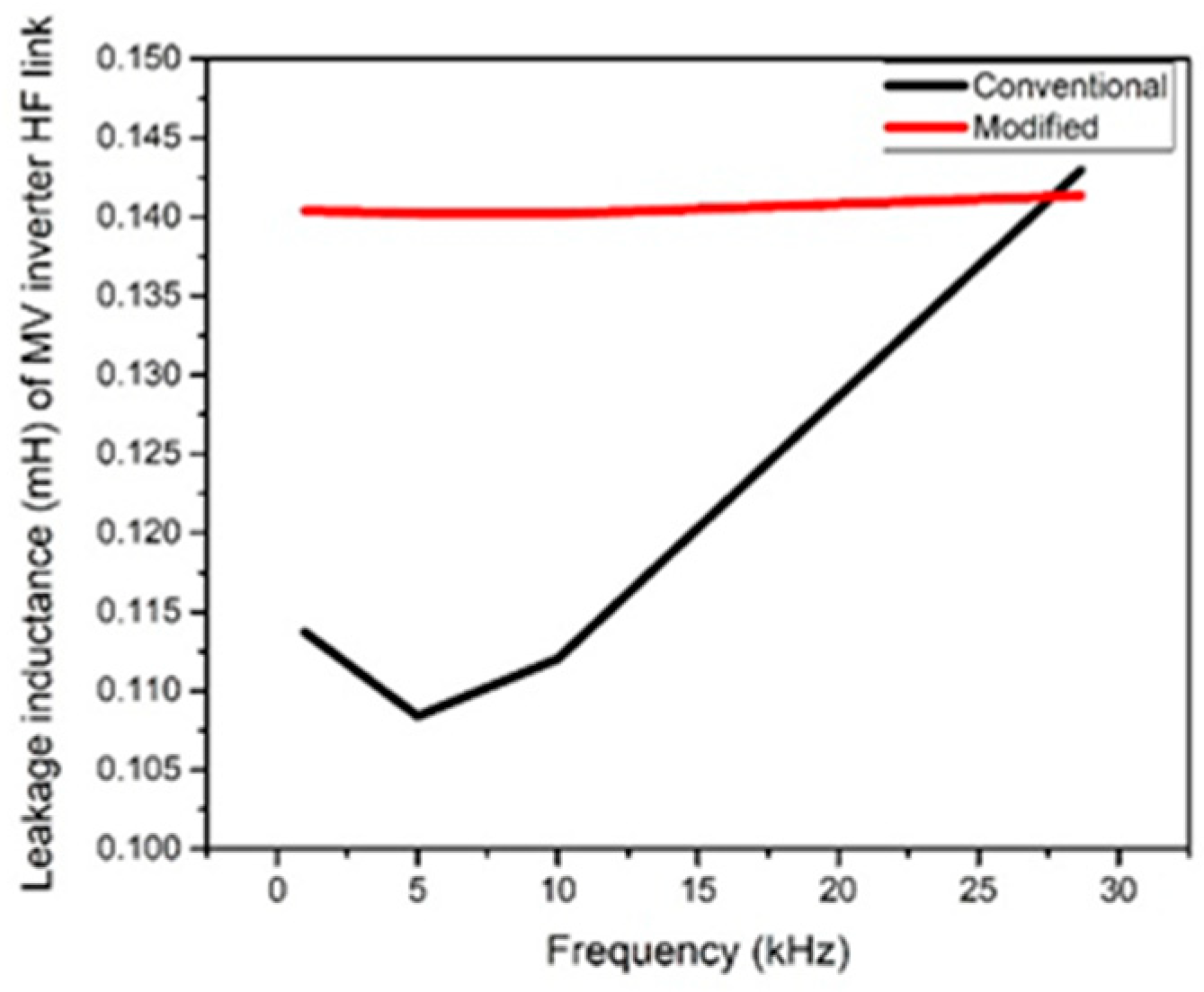
Leakage Inductance: In a sectored wound transformer, when the winding covers only 180°, leakage flux path changes in the core. According to theory, we expected the leakage inductance to be higher in modified design when compared with the conventional design because of the distance between windings created by the PLA mold. However, the 3D printed mold using PLA filament was mounted over the ferrite toroid core and secondary windings to completely encapsulate them and provided scope to increase the mean length turn of the primary winding, which is required to reduce the leakage inductance. This theory is supported by the experiment results [
37].
Figure 12 demonstrates that the modified design recorded less leakage inductance than the conventional design.
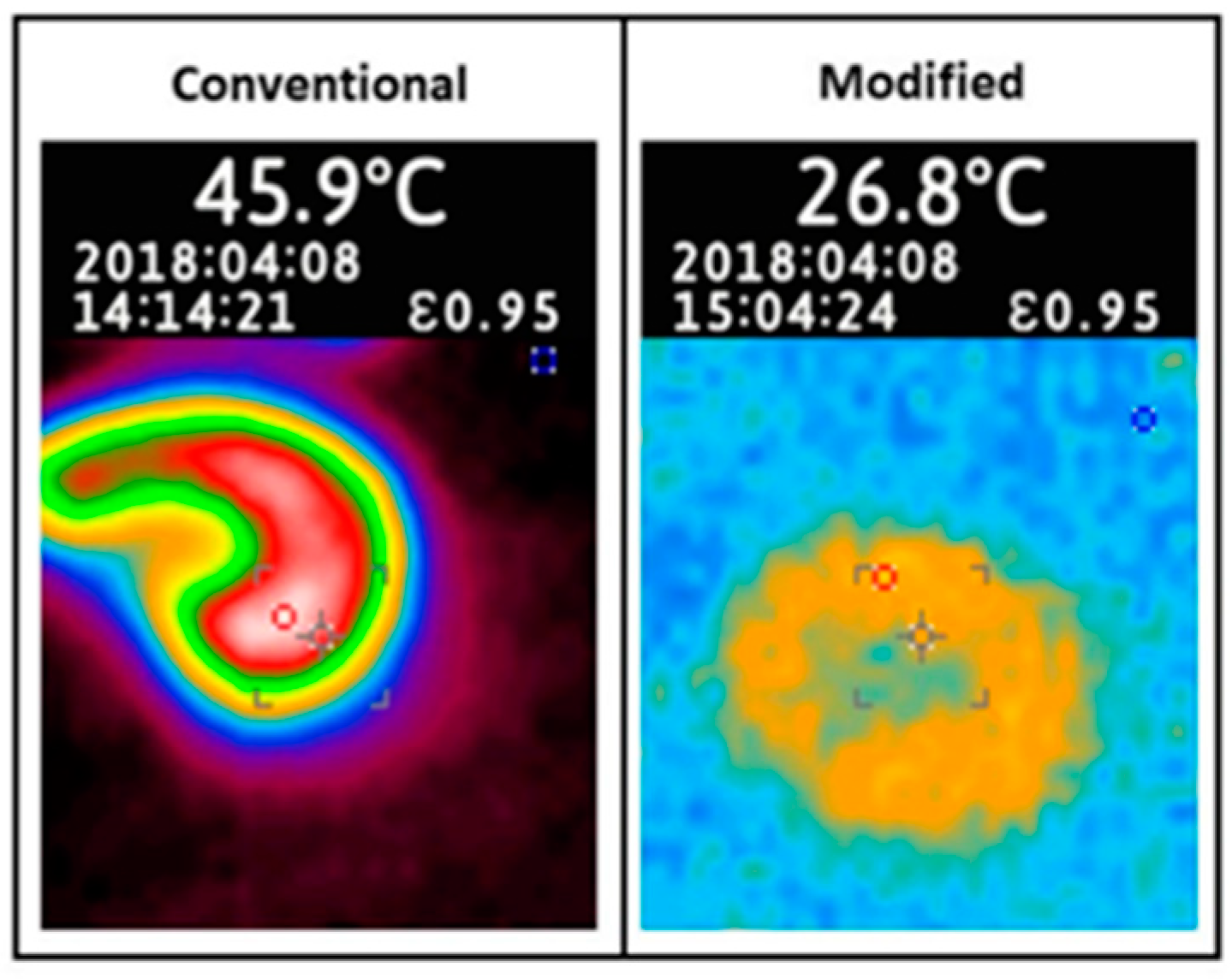
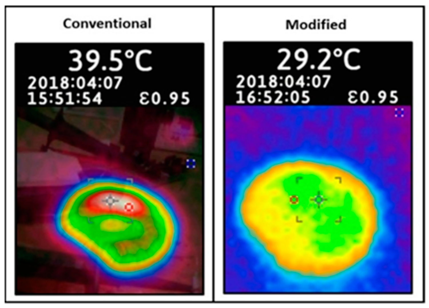
Temperature: By comparing modified and conventional transformers on full load, it is clearly visible that lowering the interwinding capacitance and harmonics distortion helped significantly in controlling the temperature rise issue in the transformer (
Figure 13).
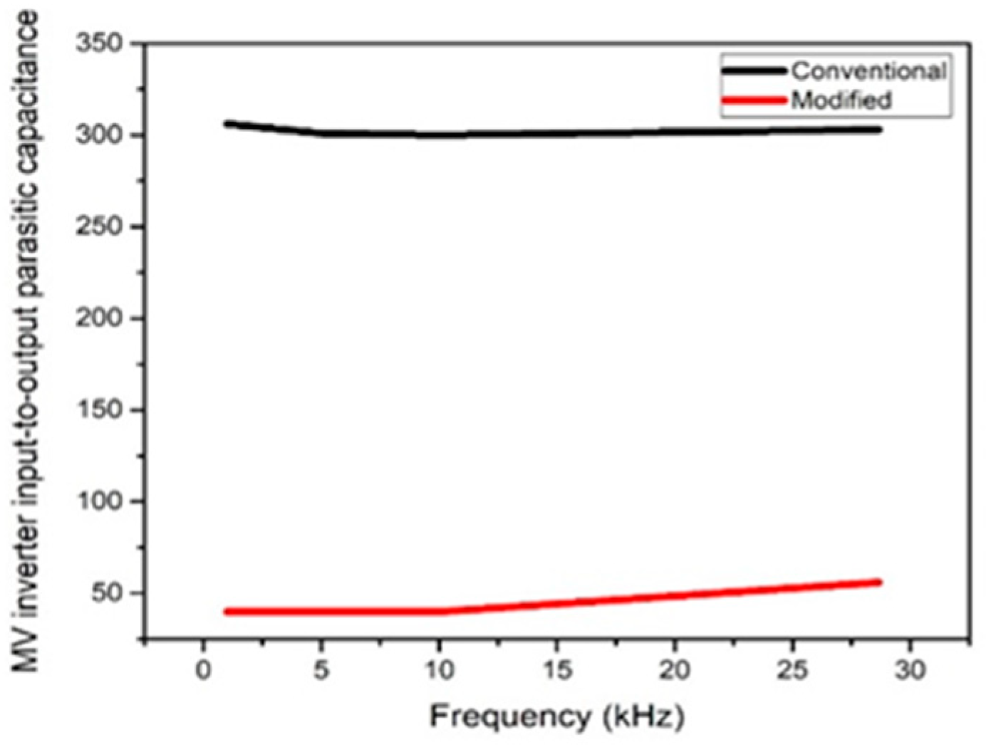
6.2. Toroidal Transformer with 360° Sectored Winding
The primary winding is on top of the secondary winding for the entire 360°, leakage flux is produced by the current in the windings, which are opposite in direction and equal in magnitude (), thus magnetizing or leakage flux cancels itself in the core.
Inter-winding Capacitance: Larger values of self-capacitance of the transformer, which occur between primary and secondary windings, play a vital role in large primary current distortions. Self-capacitance value of the proposed modified transformer prototype has been largely reduced (40 pF) with the help of 3D designed cover, spaces between windings, and proposed different winding arrangements compared with the conventional prototype. In
Figure 14, winding capacitance for both conventional and modified transformers were plotted. It is noted that the modified design succeeded in minimizing the transformer self-capacitance by approximately 87% compared with conventional designs.
Leakage Inductance: The leakage inductance and primary/secondary capacitance are mutually exclusive and are governed by the distance between the windings and unwounded core. Therefore, it is difficult to achieve both low capacitive coupling and a high degree of inductive coupling in a power transformer. However, the magnetic core geometry and winding arrangements have a large influence on self-capacitance and leakage inductance of the transformer and because of the addition of a mold, it enables access to various types of winding arrangements. Thus, the modified design has successfully lowered the inter-winding capacitance and achieves the minimum difference between leakage inductance. The experimental results are shown in
Figure 15.
Temperature: Modified design shows significant control in temperature rise by lowering the inter-winding capacitance and controlled leakage inductance over conventional designs (
Figure 16).
An MV inverter high-frequency link-modified toroid transformer was designed differently from the conventional toroid designs. Both modified prototypes, case 2 and 4, showed extremely low coupling capacitance, that is, 20 pF and 40 pF, respectively. The toroidal transformer at 180° sectored winding has registered higher leakage inductance, which can be utilized in other topologies, such as dual active bridge topologies. The experimental results matched the calculated analysis quite well. Thus, the feasibility of the converter was validated.
7. Conclusions
Overall, the MV inverter with the proposed modified transformer design has a minimized total circuit input–output capacitance to approximately 20 pF, while the temperature increase was kept below 29.5 °C, without using any extra circuitry or cooling agent. The modified design is certainly a powerful solution to reduce the distortion in the waveform. This leads to an improved power quality of renewable power sources and an increase in the operational lifetime of the devices and loads involved in power systems. Hence, the MV inverter with the modified design transformer is more robust than other available power inverters of the same power rate. These experimental measurements, which agree with the mathematical derivation, prove that the transformer shape and winding arrangements have a huge impact on the inter-winding capacitance, and cannot be ignored in power inverters when power quality improvement is of concern.
Finally, the overall result achieved with the prototype provides a very high resistance to the common mode noise current caused by rapid voltage transients, which makes the MV inverter feasible for renewable energy sources applications. For future research, a study of the optimal design method on advanced prototypes with higher inductive coupling with more controlled THD will be conducted.

 ,
, 


