Solid State Transformers Topologies, Controllers, and Applications: State-of-the-Art Literature Review


1
Department of Electrical and Computer Engineering, Curtin University, Bentley, WA6102, Australia
2
School of Engineering and Information Technology, University of New South Wales, Canberra, BC 2610 Australia
*
Author to whom correspondence should be addressed.
Electronics 2018, 7(11), 298; https://doi.org/10.3390/electronics7110298
Submission received: 16 October 2018
/
Revised: 30 October 2018
/
Accepted: 1 November 2018
/
Published: 5 November 2018
(This article belongs to the Special Issue Advanced Power Conversion Technologies)
Abstract
:With the global trend to produce clean electrical energy, the penetration of renewable energy sources in existing electricity infrastructure is expected to increase significantly within the next few years. The solid state transformer (SST) is expected to play an essential role in future smart grid topologies. Unlike traditional magnetic transformer, SST is flexible enough to be of modular construction, enabling bi-directional power flow and can be employed for AC and DC grids. Moreover, SSTs can control the voltage level and modulate both active and reactive power at the point of common coupling without the need to external flexible AC transmission system device as per the current practice in conventional electricity grids. The rapid advancement in power semiconductors switching speed and power handling capacity will soon allow for the commercialisation of grid-rated SSTs. This paper is aimed at introducing a state-of-the-art review for SST proposed topologies, controllers, and applications. Additionally, strengths, weaknesses, opportunities, and threats (SWOT) analysis along with a brief review of market drivers for prospective commercialisation are elaborated.
1. Introduction
Since the Kyoto agreement on global greenhouse-gas emissions was ratified by nearly all nations, individual countries have pledged to reduce conventional fossil fuel-based generation and integrate more renewable energy sources within electricity grids. With such enthusiasm, researchers have identified several challenges in achieving this goal. These challenges include the widespread mix of utility, individual investors and residential generation, employing cost-effective energy storage technology, adopting intelligent online monitoring and self-healing techniques, secured communication protocols, and smart control technologies. In developing future renewable system architectures, the International Renewable Energy Agency (IRENA) has identified four remarkable points in this ambitious transformation journey: enabling bi-directional energy flow, proposing improved grid interconnection, adopting enhanced technologies, and increasing energy storage capacity. To facilitate the inclusion of these features in future smart grids, a classical magnetic transformer has to be replaced with a solid state transformer (SST) that can enable bi-directional power flow. SSTs utilize a reduced-size high-frequency transformer to control the voltage level, and a range of switching devices to shape and control input and output power.
SSTs have the potential to provide extra benefits compared to a traditional transformer in terms of power quality and controllability such as output voltage control, reactive power compensation, voltage regulation (flicker compensation), and power factor correction [1,2,3,4]. With the use of advanced control strategies, other functions can be realised; for instance, SSTs can function as a unified power quality conditioner (UPQC) [5] or as an active filter [6,7].
The earliest AC–AC power electronic transformer was proposed by W. McMurray in 1970 [8], followed by the AC/AC buck converter developed by the United States Navy in 1980 [9,10]. However, due to slow switching and low power rating of semiconductors, application of SSTs in power systems could not be implemented during this era. With the latest breakthrough in power electronic industry, the Massachusetts Institute of Technology has listed SSTs as one of the ten breakthrough technologies that will influence the future of electricity grids [11]. The main advantage of SSTs over conventional transformers is the significant reduction in size due to the fact that at higher frequencies, the required size of the transformer core and windings drops dramatically [12,13]. The relation between the frequency f and overall transformer size can be approximated as [12]
where S is the output apparent power, Bm is the peak flux density, J is the current density of the conductor, Ac is the core area, and Aw is the window area. The reduced size and weight are vital for such applications as railway traction [14,15]. Size reduction at higher frequencies applies to other elements, such as capacitors and inductors. However, this reduction is counterbalanced by core hysteresis and eddy current losses, which increase with frequency [12,16]. Thus, an optimisation approach between size reduction (frequency) and efficiency was explored in [16], and optimum frequencies were determined for different core materials.
2. Solid State Transformer Topologies
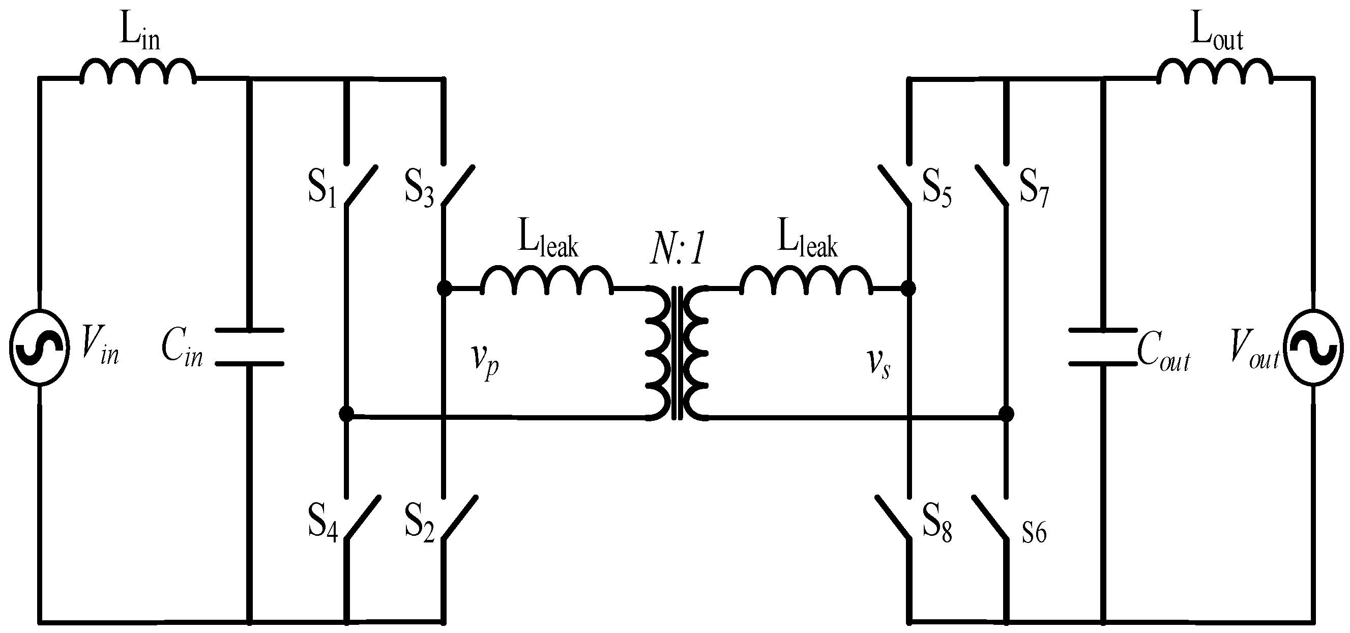
Fewer conversion stages lead to increased efficiency and improved reliability. Therefore, a single stage AC/AC conversion (as shown in Figure 1a) with a high-frequency transformer link was presented in [17,18,19]. Power transfer control in the single stage SST proposed in [17].
Figure 2 is similar to that of a typical DC/DC dual active bridge (DAB) in which the phase shift between the secondary and the primary bridges is used to control the direction and magnitude of power transfer. The proposed topology in [18] achieves bi-directional power flow by using four quadrant switches and suggests improving the control strategy to regulate harmonic content [20]. However, the single stage SST has low switching frequency and voltage conversion ratio, while the soft switching is achieved only for a limited range around the rated load. Thus, this design would be most suitable for constant load applications. The cascaded H-bridge topology is scalable to serve higher voltages, but the suggested scheme cannot provide power factor correction without additional active filters [17]. In [19], a minimal single and three phase topologies were presented. Most desired functions such as bidirectional power flow and power factor correction were achieved in this topology. The relatively high switching frequency and the low number of switching devices and absence of electrolytic capacitors make it suitable for size-critical applications.
Two stage conversion is also possible as reported in [21,22,23,24] as shown in Figure 1b. The absence of bulky capacitors in [21,22] resulted in increased power density and improved reliability. Although active rectifier was used in this topology, the control strategy was not effective in shaping the incoming current into a sinusoidal waveform. In addition, the used matrix converter requires a large number of switching devices and a complex switching scheme to achieve soft (low loss) switching [19,25]. Moreover, matrix converters have high semiconductor chip area due to the large number of active semiconductor devices [26]. Both [21,22] realize flexible power conversion and power factor correction. However, the topology presented in [22] was not able to facilitate frequency independence between the high-voltage (HV) and the low-voltage (LV) signals.
Two-stage conversion can also be attained with a DC link on the high voltage side instead of an LVDC link. This was attempted in [24] by including the high-frequency transformer in the second stage and using a cycloconverter for a direct AC–AC conversion. Soft switching was realised by a resonant converter consisting of small capacitors in parallel to each switching device that resonates with a series inductor to damp switching oscillations and achieve zero voltage switching. However, the simple control scheme does not accommodate the utilisation of the DC link as this arrangement is intended for low power applications.
The three-stage conversion topology shown in Figure 1c was presented in [1,27,28,29,30,31]. The first stage utilizes an AC/DC rectifier aimed at regulating the voltage across the HV DC link, shaping the input current [30,32], and achieving bi-directional power flow and reactive power compensation [33] as well as harmonic elimination [34,35,36]. While the second stage includes a high frequency, the DAB is required to regulate the active power flow, provide galvanic isolation, and control the voltage at the LV DC bus [33]. During this stage, the voltage is stepped up by a high-frequency transformer and transferred to an LV DC link. Finally, the voltage is shaped into a 50 Hz waveform on the load side.
Single- and multi-stage topologies were studied and compared in [37], and the three-stage configuration was found to be superior in terms of efficiency and overall power quality. Three-stage conversion topologies with proper control strategies provide maximum possible functions and controllability [3]. However, they require a large number of passive components [38].
A major advantage of multi-stage topologies is the inclusion of a low voltage DC link as reported in [30,33,39,40] in which DC loads, distributed generators, and energy storage devices can be directly connected to the SST without the need for an AC conversion stage. This is optimal for a multiport SST serving a mixture of AC devices and DC applications such as hybrid microgrids, solar PV, DC bus home, data centres [41,42,43], and optimised fast chargers of energy storage devices [3].
In a multiport multi-directional SST, active and reactive power flow control between ports is essential. In addition, multiport SSTs encompass most plug-and-play features as it accommodates different voltage levels and different loading conditions. Accordingly, the multiport SST reported in [5] can provide DC and AC at the input and output ports and regulate reactive power of each port independently, which can even be utilised to serve as a UPQC. One disadvantage of this proposed topology is that two high-frequency transformers are necessary for each phase, which may increase the imbalance between parallel modules due to inconsistencies between transformers, which causes circular currents between the modules.
3. High Voltage Solid State Transformers
SSTs with higher power rating can be achieved using three single-phase SSTs instead of the three phase matrix converters [30]. Another solution to accommodate higher voltages is by the series connection of low-voltage switching devices. The added cut-off voltages of series switching devices allow for the handling of higher voltage ratings. The drawback of these series arrangements is the high conduction loss due to the added conduction resistances [3]. Another way to serve higher power is using modular multi-level converters [40,44,45,46,47] in applications where size is not the main concern. In a modular arrangement, the HV side cells are connected in series while cells are connected in parallel on the LV side. This configuration facilitates the voltage dividing on the HV side and current dividing on the LV side. Moreover, the utilisation of multi-level converters reduces the switching losses [48]. The advantages of increasing the number of levels in the multilevel converter output voltage are reduced harmonic distortion, improved efficiency, and an ability to build fault tolerant arrangements. On the other side, the main disadvantage is the requirement of a large number of switching devices, which increases the cost and size of the SST.
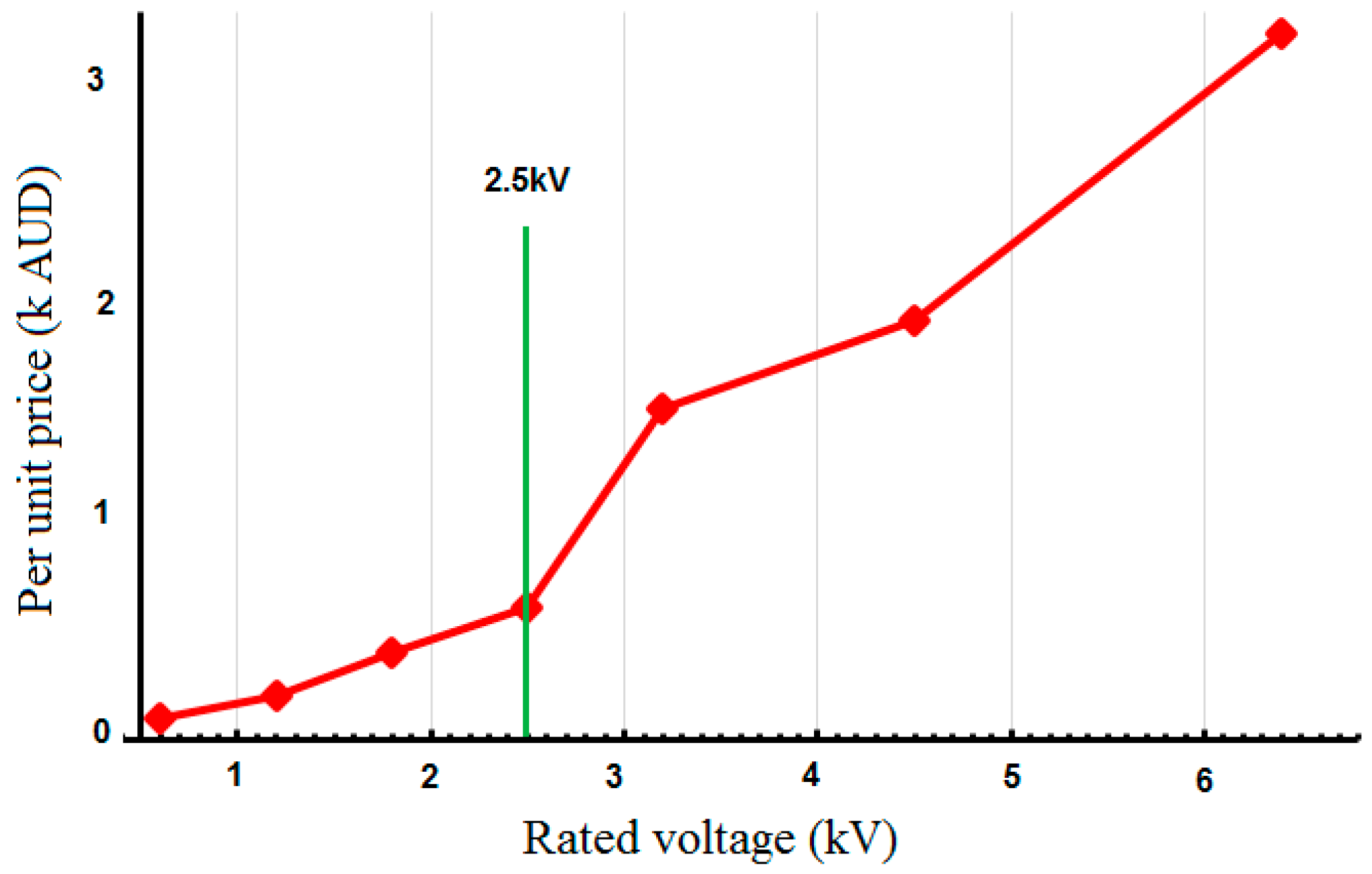
Adopting multi-level topologies to increase power rating, and equivalent switching frequency instead of using high power expensive switching devices may be more cost-efficient because below the 2.5 kV threshold the price of insulated gate bipolar transistors (IGBTs) drops drastically as shown in Figure 3 [49]. For example, in order to build an 11 kV SST using a modular topology, at least seven levels are required, as each will be supporting a DC link of 2.7 kV. The highest rating of the commercially available IGBT, which is 6.5 kV, can be used to create the 11 kV SST. Otherwise, if increased to 21 levels, the cost-effective 1.7 kV IGBT can be employed [49].
ABB adopted a multilevel three-stage arrangement for a 1.2 MVA, 15 kV SST prototype, which was field-tested on the Swiss railroad [27]. The first two stages in the arrangement were duplicated nine times and connected in series on the input side and paralleled on the output side. In pursuant of fault tolerant arrangement, N + 1 criterion was used in determining the number of modules, with the ninth module being redundant.
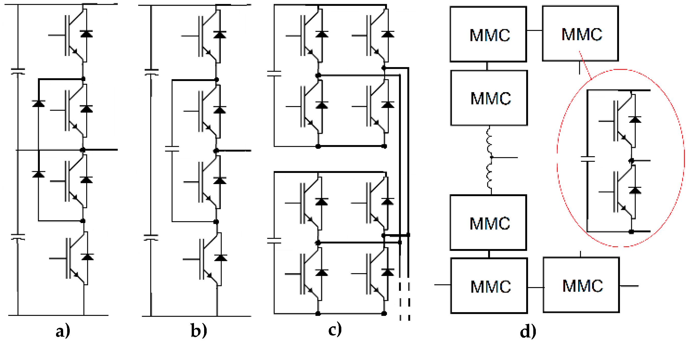
Four of the multi-level topologies proposed in the literature are shown in Figure 4. The a,b,c topologies were compared in [50], in which no major difference in terms of efficiency was reported. Cascaded H-bridge [40,51] converters and modular multi-level converters (MMCs) are the most common among recent publications because these topologies are expandable, so the power rating can be increased by adding more modules with the same architecture and control strategy [52]. They are also fault-tolerant, which guarantees fast recovery after internal faults and allows for redundant modules. Table 1 presents the four topologies. Despite the fact that flying capacitors topology require the largest number of capacitors, the MMCs and cascaded H-Bridges require the largest aluminum electrolytic capacitors to be used in the DC links as energy buffers. These capacitors are the most likely components to fail [53]. In addition, the large size capacitors undermine the size reduction prospects of SSTs [54].
In a comparison between MMCs and cascaded H-bridge converters, it was found that, at high voltages (>13.8 kV), MMC arrangement has better efficiency and semiconductor utilisation [55]. Furthermore, circulating currents [56] and voltage unbalance [57] between parallel MMCs and H-bridge modules compromise the reliability and cause voltage stress.
Instead of increasing switching levels, the rating of switching devices may be increased. There are a number of promising post-silicon technologies that can be utilised to achieve high power and high-frequency conversion. The more recent Silicon Carbide (SiC) IGBT is capable of handling 15–25 kV [59]. In addition, SiC devices can operate at higher temperatures with lower switching losses [24]. This will eventually allow the development of high-rating SSTs without the need for complex multilevel converter topologies [33,60]. Another advantage of SiC devices is the high switching frequency which can reach 10 kHz [59], while the 6.5 kV Si IGBT switching frequency is around 1 kHz at hard switching mode [59]; thus, when used in an SST, it cannot achieve the sought after reduction in core size.
When 15 kV SiC was adopted in [33], one neutral-point-clamped module was found to be sufficient to support 13.8 kV grid voltage, and a 22 kV DC link thus, achieving high power density (power/size ratio). In order to reduce cost, MOSFETs were used on the low voltage side [33], whereas the UNIFLEX 3.3 kV prototype required 12 modules using Si IGBTs [40], which undermines the size reduction achieved by using an HF transformer.
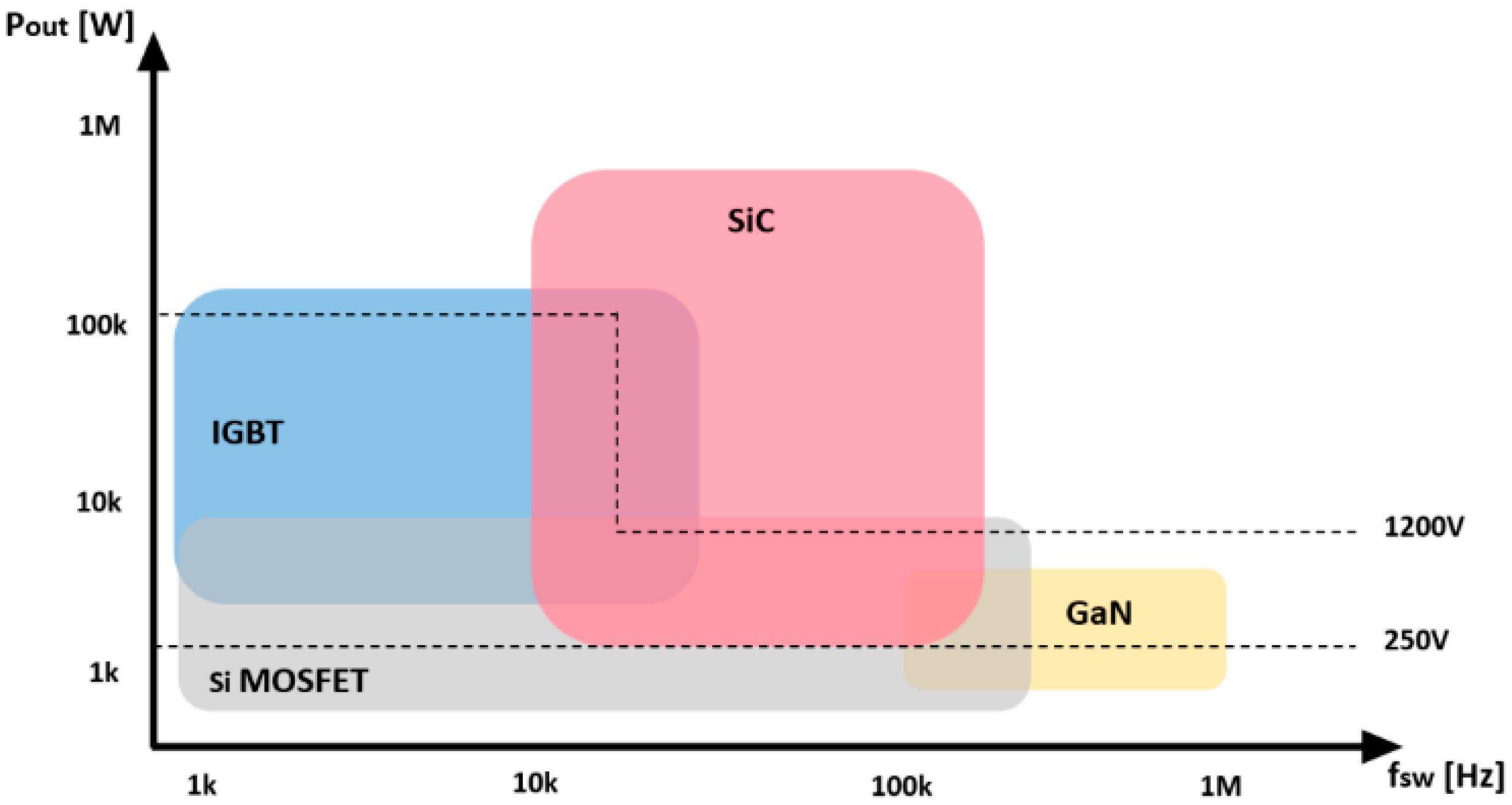
Gallium Nitride (GaN)-based power transistors are also a promising alternative to silicon-based IGBTs for applications that require fast efficient switching for up to 10 MHz [61]. Currently, breakdown voltages are limited to 1000 V. Therefore, GaN-based power transistors can be considered for SSTs serving high-end applications at a small voltage conversion range such as the tactical mobile microgrid power systems [62]. Meanwhile, SiC would be the most suitable choice for high voltage SSTs switching in the kHz frequency range. Figure 5 shows the voltage vs. frequency ratings of Si, SiC, and GaN devices.
Using a combination of different switching devices is also possible. Reference [64] suggested the use of GaN devices instead of MOSFET at the low voltage inverter stage, which increases the overall efficiency as GaN devices have lower conduction resistance. Alternatively, in [65], gate turn off thyristors (GTOs) were used for the HV rectifier for the sake of lower cost, but the disadvantage of using GTOs is the increased injected harmonics into the grid. Another way to reduce the cost of HV SSTs is by reducing the number of switching devices as in [19], but this usually leads to compromising performance or a loss of features.
4. Efficiency of Solid State Transformers
As per Australian standards, AS-2374.1.2 [66], the efficiency for high power distribution transformers must be above 98% for dry and oil immersed type rated at 100 kVA or more, which sets the bar high for SSTs to compete within the current time. It is projected that the efficiency of SSTs will continue to improve due to the use of new semiconductor technologies [9,67,68], advances in high-frequency transformers [69], and multi-objective optimisation [3]. The efficiency of SSTs depends on a number of factors such as loading, power factor, and topology. The efficiency of 50/60 Hz transformers does not vary much with loading conditions. On the contrary, efficient operation of SSTs is mostly in a limited range around the rated load, below which the efficiency drastically drops [70]. For example, in [18], at 30% of the rated load, the efficiency drops significantly as it operates outside the soft switching range. In addition, the efficiency of SSTs is affected by the power factor as feeding inductive loads interrupts inductive current, which leads to increased switching losses and may even cause over voltages and damage the switches [18].
Considering simpler topologies or the use of resonant converters were suggested to improve efficiency [71]. As expected, a comparison between single and three-stage transformers conducted in [38] proved that single-stage SSTs are more efficient. This is because soft switching techniques for a DC/DC dual active bridge in three-stage conversion schemes are well established [3]. However, hard switching is implemented in the inverter and rectifier sections [18,72].
A resonant converter such as the auxiliary snubber circuit resonant commutated pole (ARCP) although reducing switching loss, it may increase conduction losses [38]. Therefore, in order to avoid snubber circuits, multistep commutation schemes are considered with hard switching [18]. A multistep switching arrangement without a delay time or snubber circuits was suggested in [73], in which a single-stage 1 kHz SST was studied. However, other alternatives should be considered for multi-stage SSTs at higher switching frequencies.
New power semiconductor technologies may be the key to improving efficiency. Losses between 15 kV SiC IGBT and 10 kV SiC MOSFET in a three-stage arrangement were compared in [33], and the efficiency in rectifier stage only was found to be more than 99% at 10 kHz even when hard switched, and the overall measured efficiency was found to be 96.8%. Likewise, the SiC-based three-stage 2 kVA SST was presented in [68] and an efficiency of 96% during forward and reverse power flow was reported.
5. Solid State Transformers and Renewables
Typically, before transmitting electric power from a wind farm to the grid, the voltage needed to be stepped up to minimise transmission losses. Therefore, for an onshore wind turbine, the electric power flows down through high current flexible cables towards a step-up transformer at the foot of the tower. The cable needs to withstand harsh weather mechanical stress. Cable length needs to be up to three times the tower height. These cables are expensive and incur energy loss. On the other hand, for an offshore wind turbine, the step-up transformer is located in the nacelle. The bulky transformer increases mechanical loading on the tower [74]. Hence, both on- and off-shore wind generators can make use of small lightweight oil-free SSTs located in the nacelle.
Another solution suggested to reduce the size of the step-up transformer is the adoption of a transformerless MMC converter [74,75,76] that would integrate the generator to the grid and step up the voltage without the need for a step-up transformer. However, this approach requires special modular generators or multiple traditional generators to generate isolated multiple dc supplies for the MMC converter. Furthermore, it does not provide the galvanic isolation between the generator and the grid. Thus, a high-frequency link (i.e., SST) would be a more suitable solution [49].
Other benefits of SSTs is eliminating the need for an external FACTS device [29]. A FACTS device is usually connected at the point of common coupling to improve the fault-ride-through of the generator during faults and transient events as recommended in most of the publications in the literatures [29,77,78,79,80,81]. Conventional low frequency transformers are rigid, are reliable, have a long life expectancy, and can handle harsh environmental conditions. Moreover, they are expected to remain more cost-effective than SSTs in the near future. Hence, one way to justify the higher cost of the SST is the elimination of the need for other expensive devices such as FACTS [29] along with the elimination of two conventional coupling transformers and back-to-back converters, which are currently used in conventional wind energy conversion systems.
The same SST topologies suggested for distribution transformers can be adapted to integrate wind turbines to the grid. However, few SST topologies in the literature have been tailored to wind turbine integration. One of these is a 2009 paper by N. Mohan [54], which attempted to have the least number of switching devices on the HV side (Figure 6). The proposed topology presented a power electronic transformer to integrate a Type-D synchronous generator to the grid. A matrix converter was used to increase the frequency to the kHz range, and a three windings high-frequency transformer was then used to step up the voltage [82]. Two transistors connected to two windings on the grid-side were used to shape the output voltage. The advantage of this arrangement is the elimination of the bulky DC links capacitors. Moreover, only two HV switching devices are utilised. On the other hand, additional reactive power compensation is required for this topology.
A two stage matrix-based SST was presented in [21] for a variable speed constant frequency generator. The arrangement requires no capacitor in the DC link due to the high-frequency switching and the advanced modulation method used [83]. Nevertheless, the large number of switches required is a major disadvantage of this topology. Furthermore, most of these switches are located on the high voltage side. One other significant disadvantage is that this topology is not expandable to support high rating voltages. Thus, increasing the rating of switches is necessary to support higher voltages.
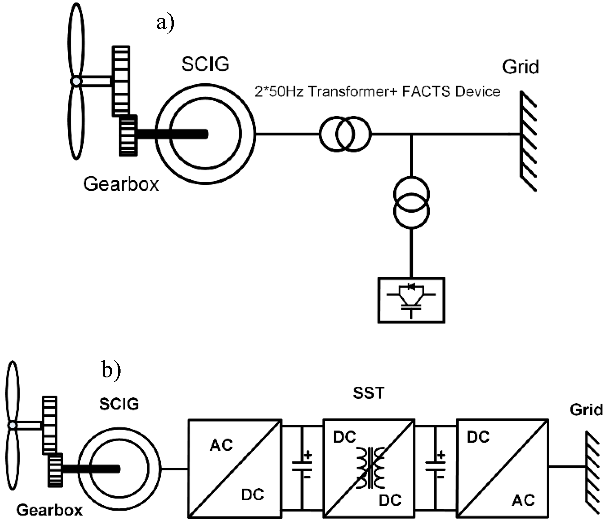
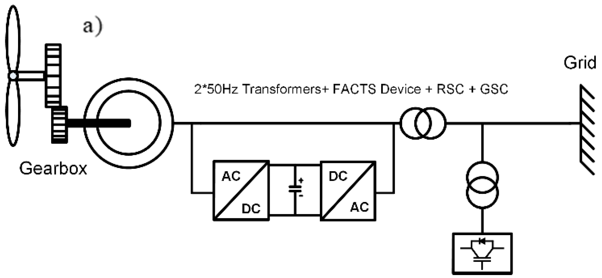
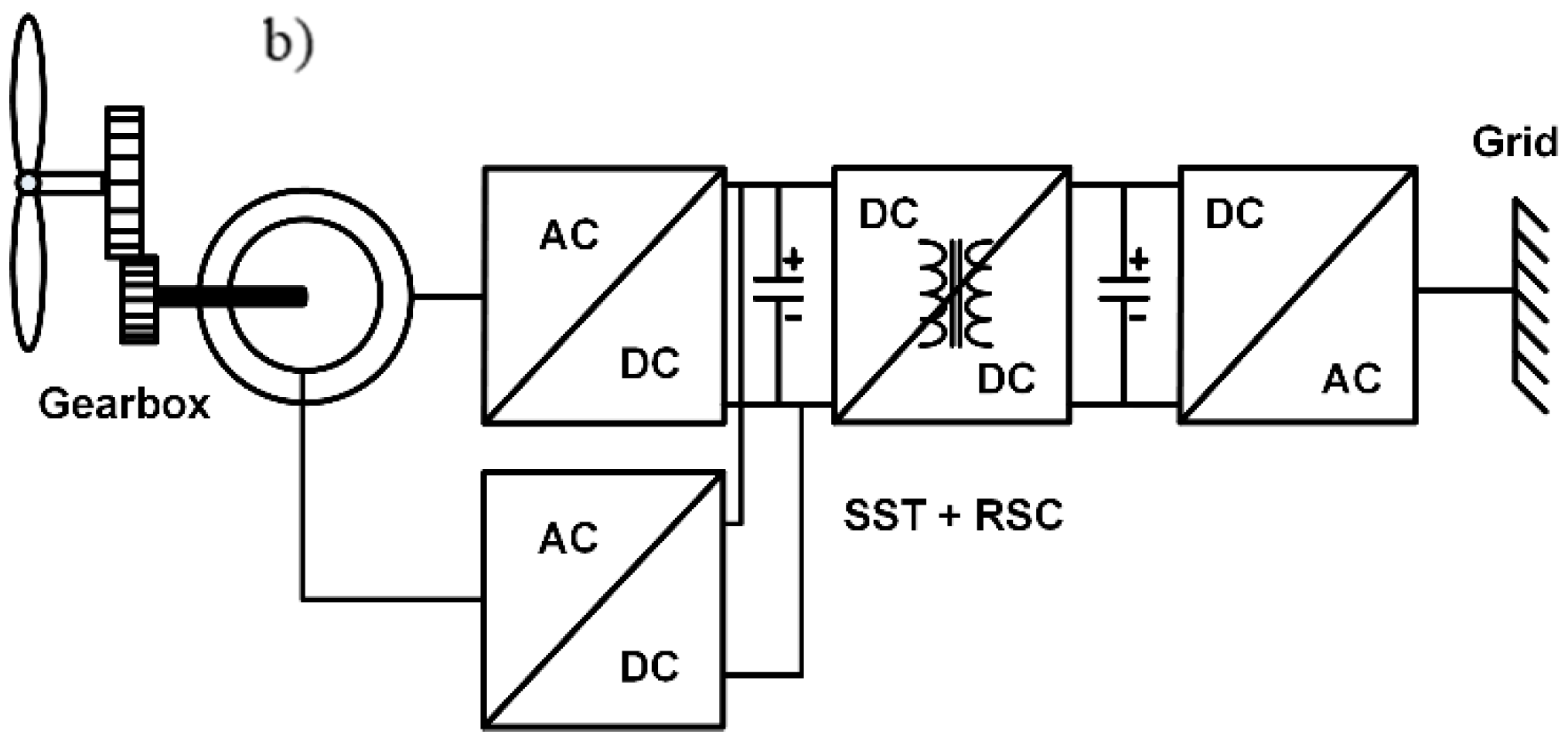
Figure 7 shows the SST arrangement proposed in [29] to integrate a squirrel cage induction generator (SCIG) to the grid. The SST successfully provided reactive power compensation for the sake of voltage regulation at sub-synchronous speeds. The work also included a modular converter arrangement for high power generators. In [28], the authors build on the work of [29] to integrate a doubly fed induction generator (DFIG) using an SST (Figure 8). The grid side converter (GSC) is eliminated by connecting the DFIG directly to the low voltage DC link. The rectifier stage is responsible for transferring active power to the DC stage, and the rotor side converter (RSC) is responsible for transferring active power from the rotor to the grid and vice versa depending on the rotor speed. At the final stage, the inverter provides reactive power support during faults and sub-synchronous speeds.
In [28,29], pitch control was omitted for simplicity. However, the same configuration with the pitch control mechanism was used in [86] to integrate a permanent magnet synchronous generator (PMSG) to the grid. The work also provides experimental results using a single-phase permanent magnet generator. Similar to [29], fault-ride-through was not discussed.
Fault Ride-Through (FRT) of Wind Turbines
With the increase in wind power penetration, grid codes became more stringent to ensure the stability and reliability of the grid is well maintained. The purpose of these codes is to make wind farms operate as closely to a conventional power plant as possible. These codes no longer allow for wind turbines to be disconnected from the grid during faults or severe voltage dips in addition, wind farms are expected to provide voltage support, reactive power regulation, and frequency response during fault events [87].
As an example, FRT requirements according to German grid code E.ON Netz [88] are classified depending on the severity of fault. In this code, wind generators are required to remain connected with a 55% voltage dip for 200 ms and withstand a 30% voltage dip for 800 ms. For the more severe faults, short-term disconnecting and reclosing is allowed within 2 s. Furthermore, the codes necessitate that the wind turbine providing voltage support by supplying reactive current during faults; for instance, 1 pu of reactive current is to be supplied when the voltage drop reaches 50%.
In case of over frequency, wind farms are required to respond by reducing the generated active power. In case of under frequency, the wind farm must respond either by changing the pitch angle to increase the power or resort to load shedding. Alternatively, wind turbines are required to keep a level of power reserve at normal operation mode [87].
For a typical DFIG at fault conditions, the grid voltage and the transferred electrical power drop, and the excess mechanical energy accelerates the rotor. Additionally, the dc voltage across the capacitor between the RSC and GSC reaches dangerous levels. There are a number of methods to limit the speed of the rotor and avoid damage without tripping the generator, such as changing the pitch angle to reduce mechanical power, increase the voltage by reactive power compensation using a STATCOM device, activate crowbar to short circuit the rotor [87], use a DC chopper to limit the DC link overcharge. [89], or connect a series breaking resistor [90].
In [29,54,86], wind turbines were integrated with the grid with an SST but fault-ride-through was not addressed. In [28], fault-ride-through capabilities of wind turbines were examined as per the German code E.ON Netz. A DC chopper at the high voltage side is used to consume generated active power while reactive fault current is injected to the grid. The inverter stage control method during faults depends on fault detection. In the case of fault, the control of the DC link voltage is ignored to supply reactive current. Without fault ride-through, the fault current and Vdc across the dc capacitor link will increase by two folds, which will cause failure to the dc link and may permanently damage the switching devices or the turbine.
It is important to note that different countries have different codes, for example, frequency response requirements are more strict in a weakly interconnected system (low inertia), such as Ireland, compared to a system belonging to the European interconnected grid. This makes it difficult for manufacturers as they struggle to interpret the latest code requirements and redesign the turbines accordingly for different markets [87].
Table 2 briefly lists the key published articles on SSTs in the last three years.
6. Future of Solid State Transformers
The commercialisation of SSTs will be driven by a set of market drivers that will encourage or restrain the demand. These market drivers are defined according to preferred features of SSTs for different applications. Figure 9 shows different market drivers for different applications on a timeline. These market drivers shall govern the development of SSTs from proof of concept to commercialisation. For instance, size reduction is crucial for wind applications, but having a DC connection is not. On the other hand, for the railway traction drive mentioned in [23], unidirectional power flow is enough [91]. While transformers serving a hybrid AC/DC grid require a multiport SST allowing power exchange between a number of branches. In military and high-end applications, the cost is not the underlining value and reliability is at most importance. For distribution transformers, size reduction will not be pushed to its limits, as it may compromise reliability because of extensive heat management requirements.
A SWOT (strengths, weaknesses, opportunities, and threats) analysis in Table 3 includes some of the inherent weaknesses that SSTs have to manage for successful commercialisation such as cost and power rating. The cost of manufacturing SSTs is expected to witness a reduction once the dynamics of economies are actuated by mass production [29]. The cost reduction will be related to the cost of semiconductors, substrate manufacturing, and the development of mass manufacturing method instead of building SSTs from discrete devices.
As shown in the SWOT (Table 3), stricter environmental legislation may represent an opportunity for the rise of SST applications. For instance, the introduction of a carbon tax is bound to boost renewables’ share in the wind energy by making them cost-competitive [92]. This increased penetration of renewables will necessitate stricter regulations, which means more power electronics are needed for voltage regulation and fault-ride-through [93]. Currently, the SST is transitioning from the domain of public research to entrepreneurial start-up companies [94,95]. Typically, the technology should start gaining patenting momentum and eventually attract larger companies, acquisitions, and more investments. However, utilities might be reluctant to make large capital expenditure (CAPEX) with unverified operational expenditure (OPEX) and life expectancy. Therefore, it is unlikely that unjustified capital investment will be made to replace distribution transformers with SSTs before a period of technology push and successful deployment by the early adopters.
The significance of the SST for utilities is that it is reflective of the future trends in the electricity grid with higher penetration of renewables and load side generators. According to the PricewaterhouseCoopers (PwC) recommendation in their 2014 “Utility of the Future” report [96] about the future of the Australian grid, those power distribution utilities shall transform into an “Energy Enablers.” The report argued that the main duty of the future distribution utilities would be to guarantee the transfer of power throughout the grid between “prosumers” in a proactive customer-oriented fashion. The latter is not far from a still conceptual view of future grid, the “Energy Internet,” in which the SST will be functioning as an energy router [97,98] with real time smart economic power dispatch [99], and the prospects of expandability and plug-and-play features [97].
Eventually, utilities will be considering SSTs as the technology matures. In addition, further deregulation and decentralisation will compel microgrids to participate in the energy market [100], and a smart multi-port SST is essential to guarantee efficient and real-time implementation of smart energy dispatch at the microgrid level [101], fast demand and frequency response, and power exchange between microgrids and the main grid [102].
7. Conclusions
The most significant challenges to current power grid models are the emergence of renewable sources, distributed generation, distributed storage, and bi-directional power flow. SSTs will play a significant role in future grid topologies. This paper presented a comprehensive review of popular SST topologies and discussed some of its applications. Papers suggesting HV SSTs using a mix of semiconductors and modular and multilevel topologies were summarised. The most recent published papers on the applications of SSTs to integrate wind turbines to the grid were reviewed. Market drivers governing the commercialisation of SSTs for different applications were defined and a SWOT analysis was presented. While SSTs are on the track of commercialisation, there are still a number of technical issues that need to be improved and managed such as efficiency, size, and reliability. Wind integration and locomotive applications are set to be the first to adopt SSTs due to many benefits and achievable high voltage levels. On the other hand, the future of SSTs in the electricity grid is driven by external and internal factors, among which are the penetration of renewables and further deregulation of the energy market.
Funding
This research received no external funding.
Conflicts of Interest
The authors declare no conflict of interest.
References
- Wrede, H.; Staudt, V.; Steimel, A. Design of an electronic power transformer. In Proceedings of the IEEE 2002 28th Annual Conference of the Industrial Electronics Society, IECON 02, Seville, Spain, 5–8 November 2002; Volume 1382, pp. 1380–1385. [Google Scholar]
- Al-Hafri, A.; Ali, H.; Ghias, A.; Nasir, Q. Transformer-less based solid state transformer for intelligent power management. In Proceedings of the 2016 5th International Conference on Electronic Devices, Systems and Applications (ICEDSA), Ras Al Khaimah, United Arab Emirates, 6–8 December 2016; pp. 1–4. [Google Scholar]
- She, X.; Huang, A.Q.; Burgos, R. Review of Solid-State Transformer Technologies and Their Application in Power Distribution Systems. IEEE J. Emerg. Sel. Top. Power Electron. 2013, 1, 186–198. [Google Scholar] [CrossRef]
- Krishnamoorthy, H.S.; Enjeti, P.N.; Sandoval, J.J. Solid-State Transformer for Grid Interface of High-Power Multipulse Rectifiers. IEEE Trans. Ind. Appl. 2018, 54, 5504–5511. [Google Scholar] [CrossRef]
- Sabahi, M.; Goharrizi, A.Y.; Hosseini, S.H.; Sharifian, M.B.B.; Gharehpetian, G.B. Flexible Power Electronic Transformer. IEEE Trans. Power Electron. 2010, 25, 2159–2169. [Google Scholar] [CrossRef]
- Bala, S.; Das, D.; Aeloiza, E.; Maitra, A.; Rajagopalan, S. Hybrid distribution transformer: Concept development and field demonstration. In Proceedings of the 2012 IEEE Energy Conversion Congress and Exposition (ECCE), Raleigh, NC, USA, 15–20 September 2012; pp. 4061–4068. [Google Scholar]
- Sepahvand, H.; Madhusoodhanan, S.; Corzine, K.; Bhattacharya, S.; Ferdowsi, M. Topology selection for medium-voltage three-phase SiC solid-state transformer. In Proceedings of the 2014 International Conference on Renewable Energy Research and Application (ICRERA), Milwaukee, WI, USA, 19–22 October 2014; pp. 485–489. [Google Scholar]
- Huber, J.E.; Kolar, J.W. Solid-State Transformers: On the Origins and Evolution of Key Concepts. IEEE Ind. Electron. Mag. 2016, 10, 19–28. [Google Scholar] [CrossRef]
- Ronan, E.R.; Sudhoff, S.D.; Glover, S.F.; Galloway, D.L. A power electronic-based distribution transformer. IEEE Trans. Power Deliv. 2002, 17, 537–543. [Google Scholar] [CrossRef]
- Brooks, J.L. Solid state transformer concept development. In Naval Material Command; Civil Eng. Lab., Naval Construction Battalion Center: Port Hueneme, CA, USA, 1980. [Google Scholar]
- Freedman, D.H. Ten Breakthrough Technologies Set to Transform our World. Technol. Rev. 2011. Available online: http://www2.technologyreview.com/news/423686/smart-transformers/ (accessed on 15 October 2018).
- Ortiz, G.; Leibl, M.; Huber, J.; Kolar, J.W. Design and Experimental Testing of a Resonant DC-DC Converter for Solid-State Transformers. IEEE Trans. Power Electron. 2016. [Google Scholar] [CrossRef]
- Ushkewar, S.; Dake, V.; Shinde, V. Designing of solid state pulse power modulator by fabrication of pulse transformer. In Proceedings of the 2017 Innovations in Power and Advanced Computing Technologies (i-PACT), Vellore, India, 21–22 April 2017; pp. 1–5. [Google Scholar]
- Carpita, M.; Marchesoni, M.; Pellerin, M.; Moser, D. Multilevel Converter for Traction Applications: Small-Scale Prototype Tests Results. IEEE Trans. Ind. Electron. 2008, 55, 2203–2212. [Google Scholar] [CrossRef]
- Ronanki, D.; Williamson, S.S. Topological Overview on Solid-state Transformer Traction Technology in High-speed Trains. In Proceedings of the 2018 IEEE Transportation Electrification Conference and Expo (ITEC), Long Beach, CA, USA, 13–15 June 2018; pp. 32–37. [Google Scholar]
- Bahmani, M.A.; Thiringer, T.; Rabiei, A.; Abdulahovic, T. Comparative Study of a Multi-MW High-Power Density DC Transformer with an Optimized High-Frequency Magnetics in All-DC Offshore Wind Farm. IEEE Trans. Power Deliv. 2016, 31, 857–866. [Google Scholar] [CrossRef]
- Hengsi, Q.; Kimball, J.W. AC-AC dual active bridge converter for solid state transformer. In Proceedings of the 2009 IEEE Energy Conversion Congress and Exposition, San Jose, CA, USA, 20–24 September 2009; pp. 3039–3044. [Google Scholar]
- Qin, H.; Kimball, J.W. Solid-State Transformer Architecture Using AC–AC Dual-Active-Bridge Converter. IEEE Trans. Ind. Electron. 2013, 60, 3720–3730. [Google Scholar] [CrossRef]
- Chen, H.; Prasai, A.; Divan, D. Dyna-C: A Minimal Topology for Bidirectional Solid-State Transformers. IEEE Trans. Power Electron. 2017, 32, 995–1005. [Google Scholar] [CrossRef]
- Masoum, A.S.; Hashemnia, N.; Abu-Siada, A.; Masoum, M.A.S.; Islam, S.M. Online Transformer Internal Fault Detection Based on Instantaneous Voltage and Current Measurements Considering Impact of Harmonics. IEEE Trans. Power Deliv. 2017, 32, 587–598. [Google Scholar] [CrossRef]
- Cha, H.J.; Enjeti, P.N. A three-phase AC/AC high-frequency link matrix converter for VSCF applications. In Proceedings of the 2003 IEEE 34th Annual Power Electronics Specialist Conference, Acapulco, Mexico, 15–19 June 2003; Volume 1974, pp. 1971–1976. [Google Scholar]
- Jin, A.; Li, H.; Li, S. A New Matrix Type Three-Phase Four-Wire Power Electronic Transformer. In Proceedings of the 2006 37th IEEE Power Electronics Specialists Conference, Jeju, Korea, 18–22 June 2006; pp. 1–6. [Google Scholar]
- Casarin, J.; Ladoux, P.; Martin, J.; Chauchat, B. AC/DC converter with medium frequency link for railway traction application. Evaluation of semiconductor losses and operating limits. In Proceedings of the SPEEDAM 2010, Pisa, Italy, 14–16 June 2010; pp. 1706–1711. [Google Scholar]
- Sabahi, M.; Hosseini, S.H.; Sharifian, M.B.; Goharrizi, A.Y.; Gharehpetian, G.B. Zero-voltage switching bi-directional power electronic transformer. IET Power Electron. 2010, 3, 818–828. [Google Scholar] [CrossRef]
- Tawfiq, K.B.; Abdou, A.F.; El-Kholy, E.E.; Shokralla, S.S. A modified space vector modulation algorithm for a matrix converter with lower total harmonic distortion. In Proceedings of the 2016 IEEE 59th International Midwest Symposium on Circuits and Systems (MWSCAS), Abu Dhabi, United Arab Emirates, 16–19 October 2016; pp. 1–4. [Google Scholar]
- Adhikari, J.; P, I.V.; Ponraj, G.; Panda, S.K. Modeling, Design, and Implementation of a Power Conversion System for Small-Scale High-Altitude Wind Power Generating System. IEEE Trans. Ind. Appl. 2017, 53, 283–295. [Google Scholar] [CrossRef]
- Dujic, D.; Zhao, C.; Mester, A.; Steinke, J.K.; Weiss, M.; Lewdeni-Schmid, S.; Chaudhuri, T.; Stefanutti, P. Power Electronic Traction Transformer-Low Voltage Prototype. IEEE Trans. Power Electron. 2013, 28, 5522–5534. [Google Scholar] [CrossRef]
- Syed, I.; Khadkikar, V. Replacing the Grid Interface Transformer in Wind Energy Conversion System with Solid-State Transformer. IEEE Trans. Power Syst. 2016. [Google Scholar] [CrossRef]
- She, X.; Huang, A.Q.; Wang, F.; Burgos, R. Wind Energy System With Integrated Functions of Active Power Transfer, Reactive Power Compensation, and Voltage Conversion. IEEE Trans. Ind. Electron. 2013, 60, 4512–4524. [Google Scholar] [CrossRef]
- Zhang, Z.; Zhao, H.; Fu, S.; Shi, J.; He, X. Voltage and power balance control strategy for three-phase modular cascaded solid stated transformer. In Proceedings of the 2016 IEEE Applied Power Electronics Conference and Exposition (APEC), Long Beach, CA, USA, 20–24 March 2016; pp. 1475–1480. [Google Scholar]
- Parseh, N.; Mohammadi, M. Solid State Transformer (SST) interfaced Doubly Fed Induction Generator (DFIG) wind turbine. In Proceedings of the 2017 Iranian Conference on Electrical Engineering (ICEE), Tehran, Iran, 2–4 May 2017; pp. 1084–1089. [Google Scholar]
- Kimura, N.; Morizane, T.; Iyoda, I.; Nakao, K.; Yokoyama, T. Solid state transformer investigation for HVDC transmission from offshore windfarm. In Proceedings of the 2017 IEEE 6th International Conference on Renewable Energy Research and Applications (ICRERA), San Diego, CA, USA, 5–8 November 2017; pp. 574–579. [Google Scholar]
- Madhusoodhanan, S.; Tripathi, A.; Patel, D.; Mainali, K.; Kadavelugu, A.; Hazra, S.; Bhattacharya, S.; Hatua, K. Solid-State Transformer and MV Grid Tie Applications Enabled by 15 kV SiC IGBTs and 10 kV SiC MOSFETs Based Multilevel Converters. IEEE Trans. Ind. Appl. 2015, 51, 3343–3360. [Google Scholar] [CrossRef]
- Madhusoodhanan, S.; Mainali, K.; Tripathi, A.; Patel, D.; Kadavelugu, A.; Bhattacharya, S.; Hatua, K. Harmonic Analysis and Controller Design of 15 kV SiC IGBT Based Medium Voltage Grid Connected Three-Phase Three-Level NPC Converter. IEEE Trans. Power Electron. 2016. [Google Scholar] [CrossRef]
- Mostafa, M.A.; Abdou, A.F.; Abd El-Gawad, A.F.; El-Kholy, E.E. SBO-based selective harmonic elimination for nine levels asymmetrical cascaded H-bridge multilevel inverter. Aust. J. Electr. Electron. Eng. 2018. [Google Scholar] [CrossRef]
- Mostafa, M.A.; Abdou, A.F.; El-Gawad, A.F.A.; El-kholy, E.E. Comparison of multi-carrier and SHE-PWM for a nine levels cascaded H-bridge inverter. In Proceedings of the 2017 Nineteenth International Middle East Power Systems Conference (MEPCON), Cairo, Egypt, 19–21 December 2017; pp. 1483–1491. [Google Scholar]
- Falcones, S.; Mao, X.; Ayyanar, R. Topology comparison for Solid State Transformer implementation. In Proceedings of the IEEE PES General Meeting, Minneapolis, MN, USA, 25–29 July 2010; pp. 1–8. [Google Scholar]
- Qin, H.; Kimball, J.W. A comparative efficiency study of silicon-based solid state transformers. In Proceedings of the 2010 IEEE Energy Conversion Congress and Exposition, Atlanta, GA, USA, 12–16 September 2010; pp. 1458–1463. [Google Scholar]
- Lai, J.s.; Maitra, A.; Goodman, F. Performance of a Distribution Intelligent Universal Transformer under Source and Load Disturbances. In Proceedings of the Conference Record of the 2006 IEEE Industry Applications Conference Forty-First IAS Annual Meeting, Tampa, FL, USA, 8–12 October 2006; pp. 719–725. [Google Scholar]
- Bifaretti, S.; Zanchetta, P.; Watson, A.; Tarisciotti, L.; Clare, J.C. Advanced Power Electronic Conversion and Control System for Universal and Flexible Power Management. IEEE Trans. Smart Grid 2011, 2, 231–243. [Google Scholar] [CrossRef]
- Zhabelova, G.; Yavarian, A.; Vyatkin, V.; Huang, A.Q. Data center energy efficiency and power quality: An alternative approach with solid state transformer. In Proceedings of the IECON 2015 41st Annual Conference of the IEEE Industrial Electronics Society, Yokohama, Japan, 9–12 November 2015; pp. 001294–001300. [Google Scholar]
- Amaral, F.V.; Parreiras, T.M.; Lobato, G.C.; Machado, A.A.P.; Pires, I.A.; Filho, B.D.J.C. Operation of a Grid-Tied Cascaded Multilevel Converter Based on a Forward Solid-State Transformer under Unbalanced PV Power Generation. IEEE Trans. Ind. Appl. 2018, 54, 5493–5503. [Google Scholar] [CrossRef]
- Liu, T.; Yang, X.; Chen, W.; Li, Y.; Xuan, Y.; Huang, L.; Hao, X. Design and implementation of high efficiency control scheme of dual active bridge based 10kV/1MW solid state transformer for PV application. IEEE Trans. Power Electron. 2018. [Google Scholar] [CrossRef]
- Ortiz, J.W.K.A.G. Solid-state-transformers: Key components of future traction and smart grid systems. In Proceedings of the International Power Electronics Conference, Hiroshima, Japan, 18–21 May 2014. [Google Scholar]
- Watson, A.J.; Dang, H.; Mondal, G.; Clare, J.C.; Wheeler, P.W. Experimental implementation of a multilevel converter for power system integration. In Proceedings of the 2009 IEEE Energy Conversion Congress and Exposition, San Jose, CA, USA, 20–24 September 2009; pp. 2232–2238. [Google Scholar]
- Hamed, H.A.; Abdou, A.F.; Acharya, S.; Moursi, M.S.E.; Kholy, E.E.E. A Novel Dynamic Switching Table Based Direct Power Control Strategy for Grid Connected Converters. IEEE Trans. Energy Convers. 2018, 33, 1086–1097. [Google Scholar] [CrossRef]
- Hamed, H.A.; Abdou, A.F.; Bayoumi, E.H.E.; Kholy, E.E.E. A Fast Recovery Technique for Grid-Connected Converters After Short Dips Using a Hybrid Structure PLL. IEEE Trans. Ind. Electron. 2018, 65, 3056–3068. [Google Scholar] [CrossRef]
- Khomfoi, S.; Tolbert, L.M. Power Electronics Handbook; Elsevier Inc.: Amsterdam, The Netherlands, 2007. [Google Scholar]
- Islam, M.R.; Guo, Y.; Zhu, J. A High-Frequency Link Multilevel Cascaded Medium-Voltage Converter for Direct Grid Integration of Renewable Energy Systems. IEEE Trans. Power Electron. 2014, 29, 4167–4182. [Google Scholar] [CrossRef]
- Sanchez-Ruiz, A.; Mazuela, M.; Alvarez, S.; Abad, G.; Baraia, I. Medium Voltage-High Power Converter Topologies Comparison Procedure, for a 6.6 kV Drive Application Using 4.5 kV IGBT Modules. IEEE Trans. Ind. Electron. 2012, 59, 1462–1476. [Google Scholar] [CrossRef]
- Zhao, T.; Wang, G.; Bhattacharya, S.; Huang, A.Q. Voltage and Power Balance Control for a Cascaded H-Bridge Converter-Based Solid-State Transformer. IEEE Trans. Power Electron. 2013, 28, 1523–1532. [Google Scholar] [CrossRef]
- Jiamin, X.; Yong, L.; Yijia, C.; Panasetsky, D.; Sidorov, D. Modeling and operating characteristic analysis of MMC-SST based shipboard power system. In Proceedings of the 2016 IEEE PES Asia-Pacific Power and Energy Engineering Conference (APPEEC), Xi’an, China, 25–28 October 2016; pp. 28–32. [Google Scholar]
- Szczesniak, P.; Kaniewski, J.; Jarnut, M. AC–AC power electronic converters without DC energy storage: A review. Energy Convers. Manag. 2015, 92, 483–497. [Google Scholar] [CrossRef]
- Gupta, R.K.; Castelino, G.F.; Mohapatra, K.K.; Mohan, N. A novel integrated three-phase, switched multi-winding power electronic transformer converter for wind power generation system. In Proceedings of the 2009 35th Annual Conference of IEEE Industrial Electronics, Porto, Portugal, 3–5 November 2009; pp. 4481–4486. [Google Scholar]
- Marzoughi, A.; Burgos, R.; Boroyevich, D.; Xue, Y. Investigation and comparison of cascaded H-bridge and modular multilevel converter topologies for medium-voltage drive application. In Proceedings of the IECON 2014 40th Annual Conference of the IEEE Industrial Electronics Society, Dallas, TX, USA, 29 October–1 November 2014; pp. 1562–1568. [Google Scholar]
- Wu, L.; Sheng, H.; Yanchao, C.; Shoudao, H. The control method of modular multi-level converter based on low and high frequency circulating current. In Proceedings of the 2014 IEEE Conference and Expo Transportation Electrification Asia-Pacific (ITEC Asia-Pacific), Beijing, China, 31 August–3 September 2014; pp. 1–6. [Google Scholar]
- Shi, J.; Gou, W.; Yuan, H.; Zhao, T.; Huang, A.Q. Research on voltage and power balance control for cascaded modular solid-state transformer. IEEE Trans. Power Electron. 2011, 26, 1154–1166. [Google Scholar] [CrossRef]
- Wang, F.; Zhang, Z.; Ericsen, T.; Raju, R.; Burgos, R.; Boroyevich, D. Advances in Power Conversion and Drives for Shipboard Systems. Proc. IEEE 2015, 103, 2285–2311. [Google Scholar] [CrossRef]
- Huang, A. Recent advances and applications of power electronics and motor drives - Power semiconductor devices. In Proceedings of the 2008 34th Annual Conference of IEEE Industrial Electronics, Orlando, FL, USA, 10–13 November 2008; pp. 28–29. [Google Scholar]
- Mainali, K.; Tripathi, A.; Madhusoodhanan, S.; Kadavelugu, A.; Patel, D.; Hazra, S.; Hatua, K.; Bhattacharya, S. A Transformerless Intelligent Power Substation: A three-phase SST enabled by a 15-kV SiC IGBT. IEEE Power Electron. Mag. 2015, 2, 31–43. [Google Scholar] [CrossRef]
- Ueda, T. Recent advances and future prospects on GaN-based power devices. In Proceedings of the 2014 International Power Electronics Conference (IPEC-Hiroshima 2014 ECCE ASIA), Hiroshima, Japan, 18–21 May 2014; pp. 2075–2078. [Google Scholar]
- Pentland, W. Why the U.S. Military Is Falling in Love with Electric Vehicles. Forbes 2013. Available online: https://www.forbes.com/sites/williampentland/2013/09/08/why-the-u-s-military-is-enamored-of-electric-vehicles/#6e851e8a5466 (accessed on 15 October 2018).
- Friedrichs, P. Future of Wide Band Gap Power Semiconductors. In Proceedings of the European Conference on Power Electronics and Applications, Karlsruhe, Germany, 5–9 September 2016. [Google Scholar]
- Ji, I.H.; Wang, S.; Lee, B.; Ke, H.; Misra, V.; Huang, A.Q. Design and fabrication of high current AlGaN/GaN HFET for Gen III solid state transformer. In Proceedings of the 2014 IEEE Workshop on Wide Bandgap Power Devices and Applications, Knoxville, TN, USA, 13–15 October 2014; pp. 63–65. [Google Scholar]
- Abedini, A.; Lipo, T. A novel topology of solid state transformer. In Proceedings of the 2010 1st Power Electronic & Drive Systems & Technologies Conference (PEDSTC), Tehran, Iran, 17–18 February 2010; pp. 101–105. [Google Scholar]
- AS-2374. Power Transformers. In Minimum Energy Performance Standards (MEPS) Requirements for Distribution Transformers; Australian Standard: Sydney, Australia, 2003. [Google Scholar]
- Grider, D.; Das, M.; Agarwal, A.; Palmour, J.; Leslie, S.; Ostop, J.; Raju, R.; Schutten, M.; Hefner, A. 10 kV/120 A SiC DMOSFET half H-bridge power modules for 1 MVA solid state power substation. In Proceedings of the 2011 IEEE Electric Ship Technologies Symposium, Alexandria, VA, USA, 10–13 April 2011; pp. 131–134. [Google Scholar]
- Zhao, B.; Song, Q.; Liu, W. A Practical Solution of High-Frequency-Link Bidirectional Solid-State Transformer Based on Advanced Components in Hybrid Microgrid. IEEE Trans. Ind. Electron. 2015, 62, 4587–4597. [Google Scholar] [CrossRef]
- Mainali, K.; Tripathi, A.; Patel, D.C.; Bhattacharya, S.; Challita, T. Design, measurement and equivalent circuit synthesis of high power HF transformer for three-phase composite dual active bridge topology. In Proceedings of the 2014 IEEE Applied Power Electronics Conference and Exposition APEC 2014, Fort Worth, TX, USA, 16–20 March 2014; pp. 342–349. [Google Scholar]
- Besselmann, T.; Mester, A.; Dujic, D. Power Electronic Traction Transformer: Efficiency Improvements Under Light-Load Conditions. IEEE Trans. Power Electron. 2014, 29, 3971–3981. [Google Scholar] [CrossRef]
- Chen, H.; Divan, D. Soft-switching solid state transformer (S4T). In Proceedings of the 2016 IEEE Energy Conversion Congress and Exposition (ECCE), Portland, OR, USA, 18–22 September 2016; pp. 1–10. [Google Scholar]
- She, X.; Yu, X.; Wang, F.; Huang, A.Q. Design and Demonstration of a 3.6-Kv–120-V/10-kVA Solid-State Transformer for Smart Grid Application. IEEE Trans. Power Electron. 2014, 29, 3982–3996. [Google Scholar] [CrossRef]
- Kang, M.; Enjeti, P.N.; Pitel, I.J. Analysis and design of electronic transformers for electric power distribution system. IEEE Trans. Power Electron. 1999, 14, 1133–1141. [Google Scholar] [CrossRef]
- Ng, C.H.; Parker, M.A.; Ran, L.; Tavner, P.J.; Bumby, J.R.; Spooner, E. A Multilevel Modular Converter for a Large, Light Weight Wind Turbine Generator. IEEE Trans. Power Electron. 2008, 23, 1062–1074. [Google Scholar] [CrossRef] [Green Version]
- Yuan, X.; Chai, J.; Li, Y. A Transformer-Less High-Power Converter for Large Permanent Magnet Wind Generator Systems. IEEE Trans. Sustain. Energy 2012, 3, 318–329. [Google Scholar] [CrossRef]
- Yuan, X.; Li, Y.; Chai, J. A transformerless modular permanent magnet wind generator system with minimum generator coils. In Proceedings of the 2010 Twenty-Fifth Annual IEEE Applied Power Electronics Conference and Exposition (APEC), Palm Springs, CA, USA, 21–25 February 2010; pp. 2104–2110. [Google Scholar]
- Ackermann, T. Wind Power in Power Systems; John Wiley & Sons Ltd.: Weinheim, Germany, 2012. [Google Scholar]
- Yunus, A.M.S.; Masoum, M.A.S.; Abu-Siada, A. Application of SMES to Enhance the Dynamic Performance of DFIG During Voltage Sag and Swell. IEEE Trans. Appl. Supercond. 2012, 22, 5702009. [Google Scholar] [CrossRef]
- Abdou, A.F.; Abu-Siada, A.; Pota, H.R. Damping of subsynchronous oscillations and improve transient stability for wind farms. In Proceedings of the 2011 IEEE PES Innovative Smart Grid Technologies, Perth, Australia, 13–16 November 2011; pp. 1–6. [Google Scholar]
- Abdou, A.F.; Abu-Siada, A.; Pota, H.R. Application of a STATCOM for damping subsynchronous oscillations and transient stability improvement. In Proceedings of the AUPEC 2011, Brisbane, Australia, 25–28 September 2011; pp. 1–5. [Google Scholar]
- Alharbi, Y.M.; Siada, A.A.; Abdou, A.F. Application of UPFC on stabilizing torsional oscillations and improving transient stability. In Proceedings of the 2013 Australasian Universities Power Engineering Conference (AUPEC), Hobart, Australia, 29 September–3 October 2013; pp. 1–4. [Google Scholar]
- Tawfiq, K.B.; Abdou, A.F.; Kholy, E.; Shokrall, S.S. Application of matrix converter connected to wind energy system. In Proceedings of the 2016 Eighteenth International Middle East Power Systems Conference (MEPCON), Cairo, Egypt, 27–29 December 2016; pp. 604–609. [Google Scholar]
- Siyoung, K.; Seung-Ki, S.; Lipo, T.A. AC/AC power conversion based on matrix converter topology with unidirectional switches. IEEE Trans. Ind. Appl. 2000, 36, 139–145. [Google Scholar] [CrossRef]
- Abdou, A.F.; Abu-Siada, A.; Pota, H.R. Improving the low voltage ride through of doubly fed induction generator during intermittent voltage source converter faults. J. Renew. Sustain. Energy 2013, 5, 043110. [Google Scholar] [CrossRef]
- Abdou, A.F.; Abu-Siada, A.; Pota, H.R. Application of STATCOM to improve the LVRT of DFIG during RSC fire-through fault. In Proceedings of the 2012 22nd Australasian Universities Power Engineering Conference (AUPEC), Bali, Indonesia, 26–29 September 2012; pp. 1–6. [Google Scholar]
- Gao, R.; Husain, I.; Wang, F.; Huang, A.Q. Solid-state transformer interfaced PMSG wind energy conversion system. In Proceedings of the 2015 IEEE Applied Power Electronics Conference and Exposition (APEC), Charlotte, NC, USA, 15–19 March 2015; pp. 1310–1317. [Google Scholar]
- Papathanassiou, M.T.S. A review of grid code technical requirements for wind farms. IET Renew. Power Gener. 2008, 3, 308–332. [Google Scholar]
- Erlich, I.; Winter, W.; Dittrich, A. Advanced grid requirements for the integration of wind turbines into the German transmission system. In Proceedings of the 2006 IEEE Power Engineering Society General Meeting, Montreal, QC, Canada, 18–22 June 2006. [Google Scholar]
- Pannell, G.; Zahawi, B.; Atkinson, D.J.; Missailidis, P. Evaluation of the Performance of a DC-Link Brake Chopper as a DFIG Low-Voltage Fault-Ride-Through Device. IEEE Trans. Energy Convers. 2013, 28, 535–542. [Google Scholar] [CrossRef]
- Causebrook, A.; Atkinson, D.J.; Jack, A.G. Fault Ride-Through of Large Wind Farms Using Series Dynamic Braking Resistors (March 2007). IEEE Trans. Power Syst. 2007, 22, 966–975. [Google Scholar] [CrossRef]
- Huang, A.Q. Medium-Voltage Solid-State Transformer: Technology for a Smarter and Resilient Grid. IEEE Ind. Electron. Mag. 2016, 10, 29–42. [Google Scholar] [CrossRef]
- Yao, F.; Dong, Z.Y.; Meng, K.; Xu, Z.; Iu, H.H.C.; Wong, K.P. Quantum-Inspired Particle Swarm Optimization for Power System Operations Considering Wind Power Uncertainty and Carbon Tax in Australia. IEEE Trans. Ind. Inform. 2012, 8, 880–888. [Google Scholar] [CrossRef]
- Rosario Llorente Iglesias. Mónica Aguado Alonso Power electronics evolution in wind turbines—A market-based analysis. Renew. Sustain. Energy Rev. 2011, 15, 4982–4993. [Google Scholar] [CrossRef]
- John, J.S. Gridco Raises $8M for the Digital-Powered Smart Grid; Greentech Media: Boston, MA, USA, 2012. [Google Scholar]
- Kanellos, M. Next for the Grid: Solid State Transformers; Greentech Media: Boston, MA, USA, 2011. [Google Scholar]
- Jock O’Callaghan, M.C.; Mezger, S.; Isles, K.; Knox, C.; Welsh, L.A. Utility of the Future (A Customer-Led Shift in the Electricity Sector); PWC: London, UK, 2014. [Google Scholar]
- Zhang, J.; Wang, W.; Bhattacharya, S. Architecture of solid state transformer-based energy router and models of energy traffic. In Proceedings of the 2012 IEEE PES Innovative Smart Grid Technologies (ISGT), Washington, DC, USA, 16–20 January 2012; pp. 1–8. [Google Scholar]
- Yi, X.; Jianhua, Z.; Wenye, W.; Juneja, A.; Bhattacharya, S. Energy router: Architectures and functionalities toward Energy Internet. In Proceedings of the 2011 IEEE International Conference on Smart Grid Communications (SmartGridComm), Brussels, Belgium, 17–20 October 2011; pp. 31–36. [Google Scholar]
- Jie, Y.; Zaijun, W.; Bhattacharya, S. Power dispatch strategy in microgrid integrated with solid state transformer. In Proceedings of the 2013 IEEE Power & Energy Society General Meeting, Vancouver, BC, Canada, 21–25 July 2013; pp. 1–5. [Google Scholar]
- Dohn, R.L. The Business Case for Microgrids; Siemens AG: Berlin, Germany, 2011. [Google Scholar]
- Hambridge, S.; Huang, A.Q.; Yu, R. Solid State Transformer (SST) as an energy router: Economic dispatch based energy routing strategy. In Proceedings of the 2015 IEEE Energy Conversion Congress and Exposition (ECCE), Montreal, QC, Canada, 20–24 September 2015; pp. 2355–2360. [Google Scholar]
- Wang, D.; Mao, C.; Lu, J.; Lee, W.J. Electronic power transformer to secure the power supply of a mission critical microgrid. In Proceedings of the 2014 IEEE Industry Application Society Annual Meeting, Vancouver, BC, Canada, 5–9 October 2014; pp. 1–8. [Google Scholar]
Figure 1.
Solid state transformer (SST) topologies: (a) single stage, (b) two stages, and (c) three stages.
Figure 1.
Solid state transformer (SST) topologies: (a) single stage, (b) two stages, and (c) three stages.

Figure 2.
Detailed single stage SST topology [17].
Figure 2.
Detailed single stage SST topology [17].

Figure 3.
Market price of insulated gate bipolar transistors (IGBTs) [49].
Figure 3.
Market price of insulated gate bipolar transistors (IGBTs) [49].

Figure 4.
Multi-level topologies: (a) Three-level neutral point clamped; (b) Three-level flying capacitor converter; (c) Cascaded H-bridge converter; (d) Modular multilevel converter [58].
Figure 4.
Multi-level topologies: (a) Three-level neutral point clamped; (b) Three-level flying capacitor converter; (c) Cascaded H-bridge converter; (d) Modular multilevel converter [58].

Figure 5.
Switching frequency vs. power rating of different semiconductors [63].
Figure 5.
Switching frequency vs. power rating of different semiconductors [63].

Figure 6.
Integrating Type D synchronous generator to the grid: (a) typical; (b) using SSTs [54].
Figure 6.
Integrating Type D synchronous generator to the grid: (a) typical; (b) using SSTs [54].

Figure 7.
Integrating a squirrel cage induction generator (SCIG) to the grid: (a) typical; (b) using SSTs [29].
Figure 7.
Integrating a squirrel cage induction generator (SCIG) to the grid: (a) typical; (b) using SSTs [29].

Figure 8.
Integrating doubly fed induction generator (DFIG) to the grid: (a) typical; (b) using SSTs [28,84,85].


Figure 9.
Market drivers on timeline vs. power rating for different SST applications.


Table 1.
Comparison of various multi-level topologies.
| Expandability | Capacitors Size | Inductors No. | Transformers No. | Semiconductors No | |
|---|---|---|---|---|---|
| Neutral point clamped | No | Low | Low | Low | High |
| Flying capacitor | No | Low | Low | Low | Low |
| H-bridge cascaded | Yes | Medium | Low | High | Low |
| MMC | Yes | High | High | Low | Low |
Table 2.
Key published articles for the SST.
| Year | Ref. | Main Focus |
|---|---|---|
| 2018 | [4] | Proposes a medium-frequency SST-based grid interface for high-power multi pulse rectifiers. |
| [15] | Reviews the SST for the traction technology in high-speed trains. | |
| [43] | Deals with the control strategy to improve dual active bridge efficiency of SSTs for PV application. | |
| 2017 | [13] | Introduces optimised parameters selection for the fabrication of compact and economical pulse transformer using split core topology. |
| [19] | Introduces a topology called dynamic-current for bidirectional SSTs with a minimal device count. | |
| [31] | Presents the application of a SST connected to a wind turbine-based doubly fed induction generator. Advantages of employing SSTs over conventional magnetic core transformer are detailed. | |
| [32] | Employs an SST for HVDC transmission of an offshore windfarm. An experimental setup is developed and comparison of 50 Hz, 400 Hz, and 1000 Hz SST operation is conducted. Dependency of the transformer losses on core materials and frequency is also investigated. | |
| 2016 | [2] | Proposes a transformerless-based SST is proposed for the intelligent power management applications. |
| [8] | Introduces the origins and evolution of key concepts of SSTs. | |
| [12] | Presents the analysis and design of a 166 kW/20 kHz dc-dc converter of a series-resonant type along with practical implementation. | |
| [28] | Proposes a configuration that combines the doubly fed induction generator-based wind turbine and SST operation to enhance the overall operation and performance. | |
| [30] | Proposes a systematic control strategy for the three-phase modular cascaded SST. | |
| [52] | Proposes a modular multilevel type SST-based topology of shipboard power system to improve the DC bus voltage stability and the power quality. | |
| [71] | Proposes a topology for a fully bidirectional soft-switching solid-state transformer to interface two- or multi-terminal dc, single- or multiphase ac systems. | |
| [91] | Discusses the needs and challenges in developing the medium-voltage SST technology for the next-generation of distribution grids. |
Table 3.
SWOT analysis for SSTs.
| STRENGTHS | WEAKNESSES |
| -Small size -Power factor correction -Reactive power support -AC/DC integration -Eliminates oil -Smart grid and economic dispatch | -High cost -Electromagnetic interference -Harmonic injection-Low power rating -Unproven reliability -Semi-conductors supply shortage |
| OPPORTUNITIES | THREATS |
| -Advances in high voltage semiconductors and mass production. -Higher penetration by renewables due to mature technology and competitive price -Government quotas and international climate agreements to reduce CO2 -Reduction in price due to mass production -Deregulation of the electricity grid requiring smart dispatch of energy and increased controllability. -Stringent standards for FRT -Rise of the electric vehicle -Large manufacturers (ex: ABB) investing in R&D | -Cost remains too high compared to benefits -Reduction in government subsidies for electrical utilities -Roll back of existing environmental accords -Stall in the development of high power semiconductors -Limited penetration of renewables due to low fossil fuel prices or CO2 capture technologies (clean coal) -Global economic recession |
© 2018 by the authors. Licensee MDPI, Basel, Switzerland. This article is an open access article distributed under the terms and conditions of the Creative Commons Attribution (CC BY) license (http://creativecommons.org/licenses/by/4.0/).
Share and Cite
MDPI and ACS Style
Abu-Siada, A.; Budiri, J.; Abdou, A.F. Solid State Transformers Topologies, Controllers, and Applications: State-of-the-Art Literature Review. Electronics 2018, 7, 298. https://doi.org/10.3390/electronics7110298
AMA Style
Abu-Siada A, Budiri J, Abdou AF. Solid State Transformers Topologies, Controllers, and Applications: State-of-the-Art Literature Review. Electronics. 2018; 7(11):298. https://doi.org/10.3390/electronics7110298
Chicago/Turabian StyleAbu-Siada, Ahmed, Jad Budiri, and Ahmed F. Abdou. 2018. "Solid State Transformers Topologies, Controllers, and Applications: State-of-the-Art Literature Review" Electronics 7, no. 11: 298. https://doi.org/10.3390/electronics7110298
Note that from the first issue of 2016, this journal uses article numbers instead of page numbers. See further details here.