Article

FPGA-based Chaotic Cryptosystem by Using Voice Recognition as Access Key

by
Eduardo Rodríguez-Orozco
1,
Enrique Efren García-Guerrero
1,
Everardo Inzunza-Gonzalez
1,
Oscar Roberto López-Bonilla
1,
Abraham Flores-Vergara
1,
Jose Ricardo Cárdenas-Valdez
2 and
Esteban Tlelo-Cuautle
3,*
1
UABC, Engineering, Architecture and Design Faculty, 22860 Ensenada, Baja California, Mexico
2
ITT, Department of Electrical and Electronics Engineering, Tijuana Institute of Technology, 22435 Tijuana, Baja California, Mexico
3
INAOE, Department of Electronics, 72840 Puebla, Mexico
*
Author to whom correspondence should be addressed.
Electronics 2018, 7(12), 414; https://doi.org/10.3390/electronics7120414
Submission received: 7 November 2018 / Revised: 28 November 2018 / Accepted: 5 December 2018 / Published: 9 December 2018
(This article belongs to the Section Systems & Control Engineering)

Abstract

:
A new embedded chaotic cryptosystem is introduced herein with the aim to encrypt digital images and performing speech recognition as an external access key. The proposed cryptosystem consists of three technologies: (i) a Spartan 3E-1600 FPGA from Xilinx; (ii) a 64-bit Raspberry Pi 3 single board computer; and (iii) a voice recognition chip manufactured by Sunplus. The cryptosystem operates with four embedded algorithms: (1) a graphical user interface developed in Python language for the Raspberry Pi platform, which allows friendly management of the system; (2) an internal control entity that entails the start-up of the embedded system based on the identification of the key access, the pixels-entry of the image to the FPGA to be encrypted or unraveled from the Raspberry Pi, and the self-execution of the encryption/decryption of the information; (3) a chaotic pseudo-random binary generator whose decimal numerical values are converted to an 8-bit binary scale under the VHDL description of m o d ( 255 ) ; and (4) two UART communication algorithms by using the RS-232 protocol, all of them described in VHDL for the FPGA implementation. We provide a security analysis to demonstrate that the proposed cryptosystem is highly secure and robust against known attacks.

1. Introduction

Chaotic systems have shown their usefulness in practical applications focused on security, and they have been implemented with different kinds of electronic devices [1,2,3,4]. In the case of designing cryptosystems, currently one can found different encryption standards, such as: TDES (Triple Data Encryption Standard), ASD (Advanced Encryption Standard), Blowfish and IDEA (International Data Encryption Standard), from which one must be aware that when attacked with dedicated software, they show weaknesses under certain conditions. Other encryption schemes based on S-Box, watermarking and hiding of information have been published in [5,6,7,8,9]. In this line for research, other conventional and non-conventional encryption algorithms have been proposed to provide solutions to the constant demand for security in processing digital information. For instance, an unconventional encryption technique that uses chaos theory was proposed by Pecora and Carroll [10]. That way, the properties of chaotic dynamical systems of seemingly erratic behaviors such as ergodicity and deterministic dynamics adjust in an appropriate way to the requirements posed by cryptography, such as: confusion and pseudo-randomness. In this manner, chaotic behavior is being a viable and reliable alternative to the implementation of information encryption systems [11].
In the last decade, a lot of researchers have introduced chaotic techniques that have been implemented in information encryption systems. For example: the authors in [12,13,14,15,16,17,18] proposed different methods to generate pseudorandom sequences that are verified by performing statistical tests of the Federal Information Processing Standards (SP 800-22) [19] of the National Institute of Standards and Technology (NIST), to evaluate their levels of randomness. In [20], a Chaotic Pseudorandom Binary Generator (CPRBG) was presented and synchronized to another CPRBG to perform image encryption. By the same time, a CPRBG algorithm was implemented in an Arduino microcontroller [21], which was based on a pair of Logistic maps and a skewed technique with the XOR binary operation. Likewise and more recently, novel implementations have been developed by using reconfigurable hardware such as Field Programmable Gate Arrays (FPGAs), which provide an excellent balance between the computational power and the processing flexibility [17,22,23,24,25,26,27,28]. Other FPGA implementations of chaotic systems and maps have been applied to image encryption [29]. In the same way, the authors in [30] implemented a Chaotic Pseudo-Random Number Generator (CPRNG) in an FPGA using the System Generator tool (SysGen) developed by Xilinx. With respect to patterns recognition for biometric and medical applications, several works have been reported in the literature, see for example [31,32,33,34,35].
In this work, we introduce a new embedded chaotic cryptosystem to process digital images and performing voice recognition as an external access key. In this manner, our proposed cryptosystem consists of three technologies: (i) a Spartan 3151-1600 FPGA from Xilinx; (ii) a 64-bit Raspberry Pi 3 single board computer; and (iii) a speech recognition chip (SRC) manufactured by Sunplus. The operability and efficiency of the proposed cryptosystem is evaluated with the study and analysis of the level of security of the encryption and decryption of different digital images, under the implementation of several chaotic maps, namely: Hénon [36], Karplan–Yorke [37], 2D Logistic [38], Tinkerbell [39] and Rössler [40]. It is worth mentioning that each one of the chaotic signals generated by these maps is tested by the SP 800-22 standard of NIST, to evaluate their levels of randomness and provide high security. An important feature of this work is the application of the m o d ( 255 ) function, which is implemented in an FPGA. We highlight the importance of this basic operation for many encryption algorithms reported in the literature that use computers or microprocessors, our approach is derived from the implementation itself that entails the adequate operation of the different technologies that integrate the system, from the synchronized execution of their respective embedded algorithms under a concurrent programming environment governed by the FPGA.
The rest of this manuscript is organized as follows: Section 2 details the proposed embedded cryptosystem, describing its technologies and its connectivity at the hardware level. Section 3 describes the embedded algorithms that make possible the interrelation of the different technologies that setup the proposed cryptosystem, as well as the adequate execution of the encryption or decryption of an image that can be captured in situ or that is stored in the memory. We also detail the synchronized execution of the respective embedded algorithms under a concurrent programming environment governed by the FPGA. Section 4 shows the results of the statistical analysis of encryption and decryption of images under different chaotic maps, as well as the SP 800-22 statistical test suite of NIST to the pseudorandom binary sequences obtained with the implemented maps. Section 5 summarizes the conclusions of this work.

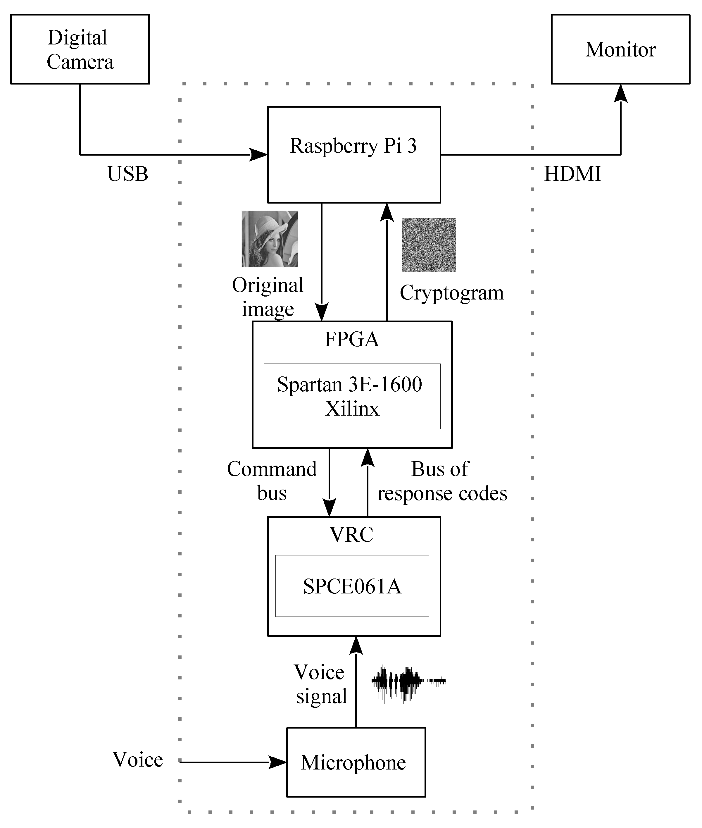
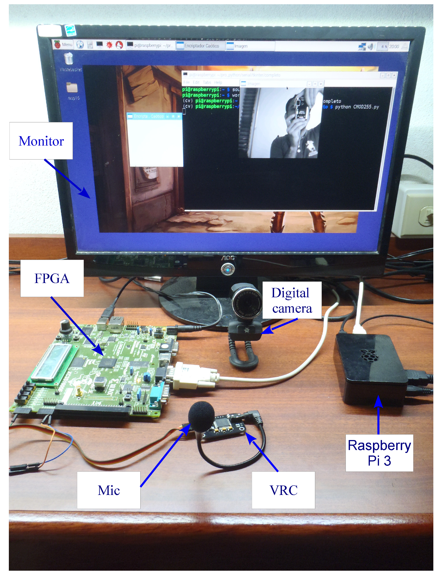
2. Proposed Embedded Cryptosystem

An embedded chaotic encryption system of digital images with speech recognition as an external access key is presented. The cryptosystem is integrated by three subsystems with their own technologies: (i) the main control subsystem, comprised of an FPGA (Field Programmable Gate Array) Spartan 3E-1600 of Xilinx; (ii) a capture and deployment subsystem, integrated by a Single Board Computer Raspberry Pi 3 BCM2835 of 64-bit; and (iii) a subsystem of recognition, which operates with a voice recognition chip (VRC) manufactured by the company Sunplus. Figure 1 shows a block diagram of the proposed system. The operability of the system is focused on the synchronization of the parallel communication executed by the FPGA with the SRC and the Raspberry Pi. Access to the system is delimited by the voice recognition subsystem through the VRC when it validates the word a user pronounces with the one authorized and previously recorded in its memory bank. When one have access to the cryptosystem, the capture and deployment subsystem through a graphical interface (GI) developed through Python, allows to choose among three basic functions: (i) select the image type; (ii) start the encryption or decryption process; and (iii) exit the system. Meanwhile, the selected image is displayed on a monitor and it can either be stored in the Raspberry Pi’s Micro-SD memory or taken in situ by the integrated digital camera (CD) that is embedded into the proposed system.
When the encryption process begins, the capture and display subsystem (Raspberry Pi) sends each pixel of the original image through one of its USB ports to the RS-232 port of the main control subsystem through FPGA. When a pixel enters the FPGA, a chaotic state ( X N ) whose decimal numerical value is converted to a binary scale of magnitude 8 bits ( x n ) is simultaneously generated. Under these conditions from the logic operation XOR, each pixel is masked with the numerical value of the binary chaotic state ( x n ) thus generating an encrypted pixel. Each encrypted pixel is forwarded to the capture and display subsystem to integrate the relative cryptogram to the original image. At the end of the encryption of all the pixels that make up an image, the cryptogram is displayed on the monitor and stored simultaneously in the Micro-SD memory. The embedded chaotic encryption algorithm in the main control subsystem has a simple operational logic, allowing to execute without distinction the encryption or decryption processes, without any change in software or hardware in the system, the implementation of a chaotic map with dynamic behavior of any level of complexity and to reach competitive levels in security against different types of analysis and attacks.
The main hardware elements of the proposed embedded cryptosystem are shown in Figure 2, and they are detailed in the following sub-sections.

2.1. Spartan 3E-1600 from Xilinx

It is a development card with an FPGA chip capable of integrating into different processes due to intrinsic parallelism. It is the core of the proposed system, its objective is encrypting and decrypting a digital image by using a chaotic map, as well as establishing communication with the VRC and the Raspberry Pi.

2.2. SPCE061 A Speech Recognition Chip with Microphone

It is a microcontroller used in applications of digital sound processing and speech recognition. Its objective is to identify the authorized word pronounced by a user and send, when appropriate, a start code to the FPGA [41].

2.3. Raspberry Pi 3 B

It is a Broadcom BCM2835 64-bit high performance, versatile and friendly on-chip system (SoC). It uses a Micro-SD card for permanent information storage and has 17 GPIO ports (Input/Output), SPI, I2C, and a Universal Asynchronous Receiver Transmitter (UART). In this work, it is used to develop a friendly and intuitive Graphical Interface (GI) by using Python language.

2.4. Peripherals Connected to the Raspberry Pi

Monitor with HDMI video input, generic keyboard and mouse with USB outputs, and Logitech QuickCam Pro 9000 digital camera for in-situ image capture with a resolution of 640 × 480 pixels.
Figure 3 shows a block diagram of the elements in hardware that setup the main control subsystem and the processes run around the encryption or decryption of digital images. The control of the processes are established by the FPGA from a Control Entity by two sub-entities: the access authorization and the XOR encrypter. It also shows the entity CPRBG, responsible for generating binary chaotic states relative to a selected mapping. At the same time, the main control subsystem maintains communication in parallel with the capture and display and recognition subsystems, through the UART 1 and UART 2 communication ports. The general system works under five algorithms:
(i)
a developed graphical interface in Python language for the Raspberry Pi platform, which allows the friendly management of the system; and four algorithms described in the VHDL language for the FPGA are, which are:
(ii)
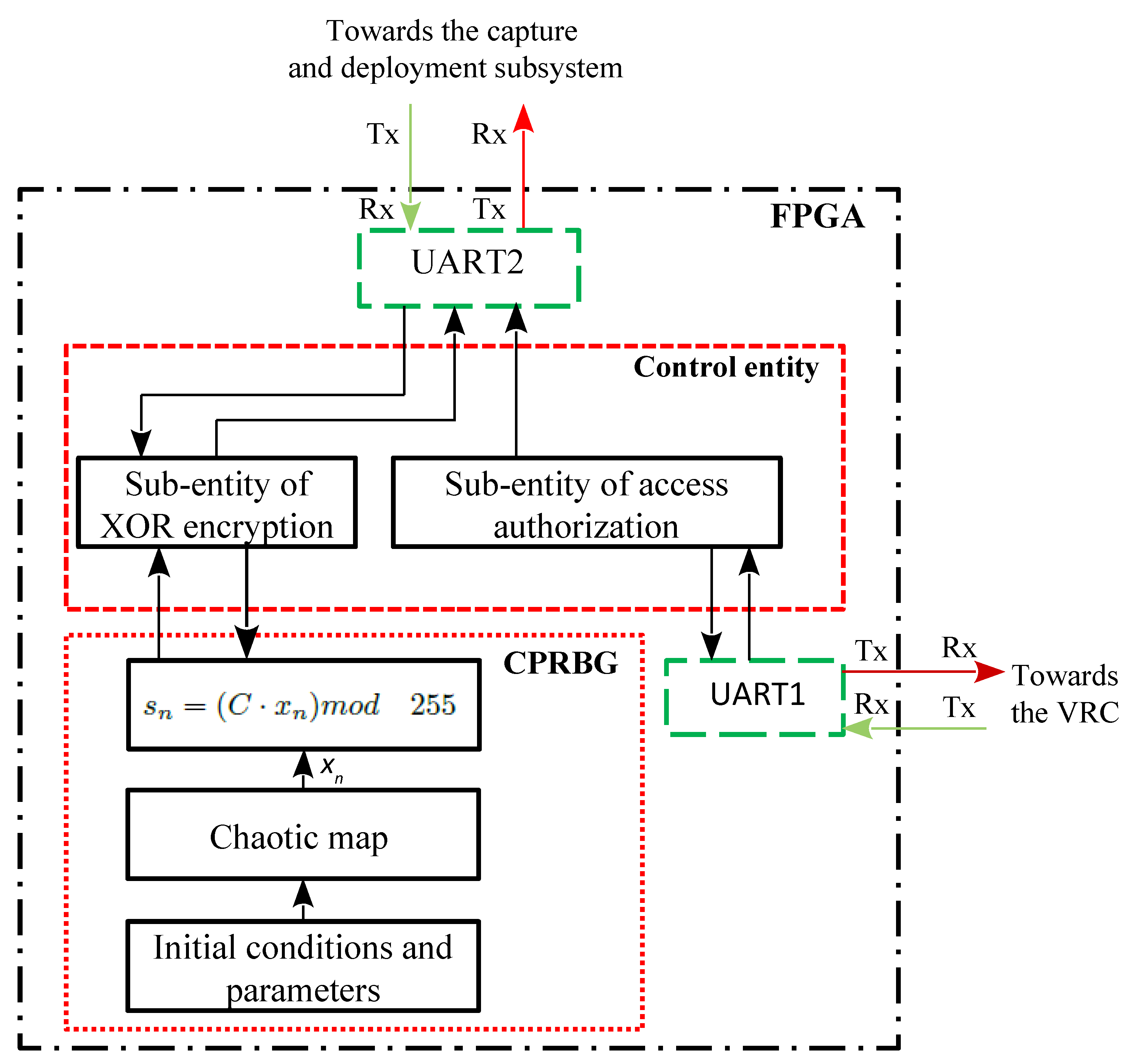
an internal control algorithm that entails the operational logic of the system allowing, among other functions: (a) the start-up of the embedded system from the identification of the access keyword; (b) the entry of the pixels of the image to be encrypted or decrypted from the Raspberry Pi into the FPGA; and (c) the own execution of the encryption or decryption by using the logical operation XOR,
(iii)
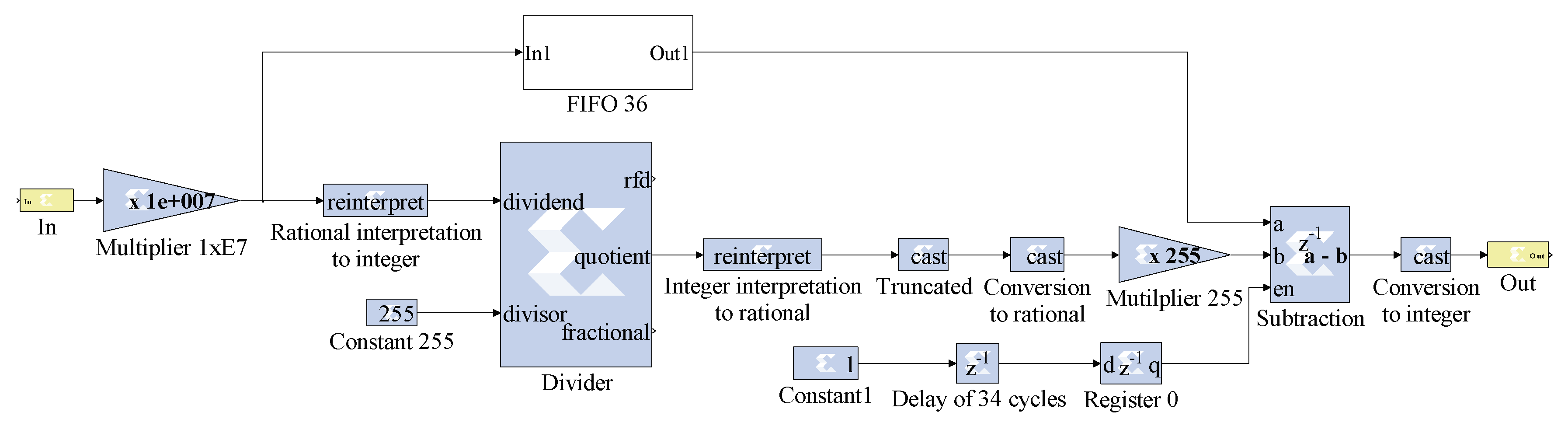
a CPRGB algorithm whose decimal numerical values are adapted to an 8-bit binary scale under the VHDL implementation of the m o d ( 255 ) operation, and
(iv)
conditioning of two UART communication algorithms developed from the RS-232 protocol and integrated by the GNU library, and which correspond to the communication between the FPGA with the speech recognition chip (UART1) and with the Raspberry Pi (UART2).

3. Embedded Algorithms

3.1. Internal Control

In relation to Figure 3, the Control Entity operates under an internal control algorithm. The algorithm considers an access authorization sub-entity. In general, this Control entity performs three basic processes: (a) the start-up of the system based on the validation of the keyword pronounced by a user; (b) the first entry to one of the pixels of the image to be encrypted or decrypted from the Raspberry Pi; and (c) the own execution of the encryption or decryption from the logical XOR operation. The execution of these processes requires being started with the VRC. In addition to Figure 3, the algorithm starts with the configuration and enabling of the communication through the serial port UART1, the physical connection between the FPGA and the VRC is validated, the VRC is configured in short working mode, and it is executed the load of a speech bank (authorized word). Under the execution of these stages, the VRC is able to allow or not access to the system, from validating the word that a user utters. When access is authorized, the serial port UART2 is configured and the FPGA sends an access code to the Raspberry Pi. Experimentally the FPGA-VRC connection is through the RS-232 communication port. Specifically from port J 1 of the FPGA and consisting of six pins, pin B4 is configured as input Rx and pin A4 as output Tx. The characteristic supply voltage is 5 V, the logic levels are defined by the voltage range between 0–0.8 V for the Low logic (low) state and between 3.5 and 5 V for the H (high) logic state. Port J 1 supports 3.5–5 V, and the voltage configuration is given by means of VHDL programming. The SPCE061A speech recognition chip from Sunplus has a previously loaded algorithm consisting of two communication modes: short and extended; It consists of three blocks with five fields each which allows to store up to fifteen speech instructions, however, the algorithm is independent from the user and false positives may occur, so a peculiar access code must be selected. Each analog audio signal is linked to an output in hexadecimal code depending on the working mode. Once the UART2 serial port derived from the authorization to access the system is enabled, the XOR encryption sub-entity receives a start bit, indicating in parallel that there is a data ready to be sent from the capture and display subsystem. The data to be received corresponds to a pixel of the image to be encrypted or decrypted as appropriate. When the corresponding pixel is received, the CPRBG Entity is enabled and sends the S n data corresponding to an 8-bit pseudorandom binary number to the Encryption sub-entity XOR. When the S n data is sent, the CPRBG Entity is disabled. Finally, in the encryption sub-entity, the binary operation XOR is executed between the pixel of the image and chaotic data in S n binary format, obtaining an encrypted or decrypted data as the case may be. The encrypted/decrypted data is sent through the serial port UART2 to the capture and display subsystem (Raspberry Pi).

3.2. Chaotic Pseudo Random Binary Generator (CPRBG) Algorithm
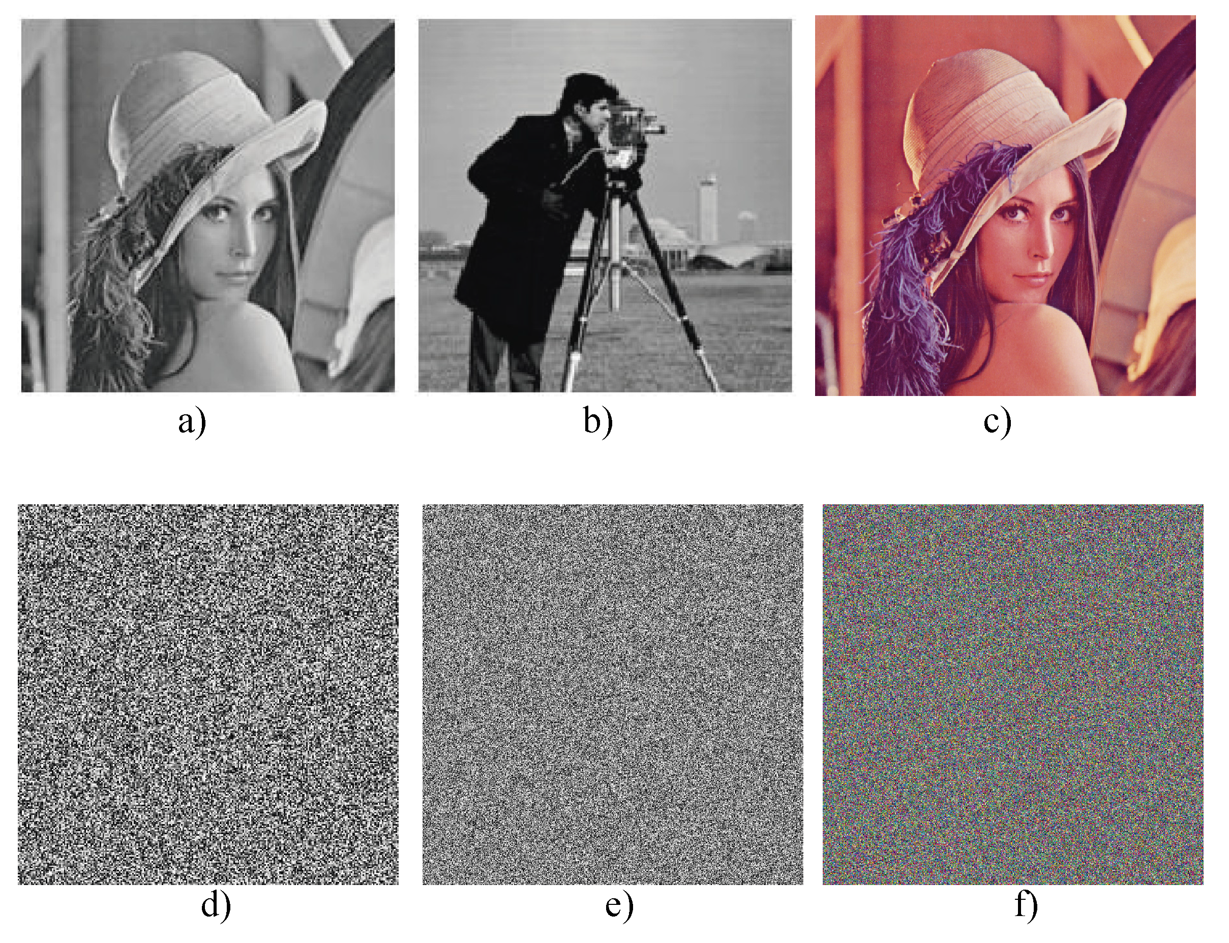
Figure 3 depicts the CPRBG sub-entity as part of the main control subsystem and is responsible for generating the chaotic pseudo-random binary sequences from the following basic processes: (a) implementation of a chaotic map and; (b) adaptation of the chaotic state x n to a binary scale S n of 8 bits. In relating to the XOR encryption sub-entity implies that the entity CPRBG operates cyclically, enabling itself to generate and send an S n data, then standing by waiting until it receives again the indication to generate and send a new S n data. The CPRBG sub-entity performs the calculation of the x n chaotic state and the conditioning of the x n data to a S n binary scale. The first block contemplates: (a) the selection of a chaotic map as a basis for the generation of chaos; (b) the generation of the VHDL code corresponding to the system of differential equations of the chaotic system; and (c) the implementation of the chaotic system in the FPGA. In this work, the chaotic maps of Hénon [36], Karplan-Yorke [37], 2D Logistic [38], Tinkerbell [39] and Rössler [40] were selected without any specific criteria and as an example. Each map was described into VHDL code and implemented in the FPGA as follows: When a x n state relative to the chaotic map is generated, a real number (float) is obtained, which, in order to be able to mask the value of a pixel of the corresponding image, is conditioned to an 8 bit binary S n data from the Equation (1)
S n = ( C × x n ) m o d ( 255 ) ,
where C = 10 × 10 6 . The m o d ( 255 ) operation is described by the system of Equation (2),
m o d ( x , y ) = x n y ,
n = f l o o r ( x / y ) ,
and it is implemented in FPGA by using the SysGen ToolBox in Matlab’s Simulink.
Figure 4 depicts the block diagram of the m o d ( 255 ) operation implemented in the FPGA, based on Equations (1) and (2). Equation (1) contemplates the x n variable that corresponds to one of the states of the equations on differences that describe the respective chaotic map, which are represented by real numbers of a fixed point in the FPGA. This value is the Input shown in the figure with mantissa 32Q23, with one sign bit, 8 bits of an integer part and 23 bits of a fractional part. This data is multiplied by the constant C = 1 × 10 7 to move the decimal point seven times to the right and obtain a data with mantissa 32Q8 and then by the m o d ( 255 ) function. The implementation of the division operation present in the m o d ( x , y ) function defined by Equation (2), is conditioned in Simulink by the block that provides SysGen of Xilinx since it operates only with signed integers. Under this condition, as shown in the figure, the rational input data 32Q8 to the Divider is reinterpreted to an integer 32Q0 to execute the division with the constant 255; the obtained number at the exit (quotient) has a mantissa of 32 bits and is an integer and without a sign, which is returned to its original rational condition of 32Q8. After the division executed in Equation (2) the floor function is followed. This operation is not part of the package that provides SysGen of Xilinx, so, from its mathematical definition in the figure is represented by the blocks Truncated (cast) and Conversion to rational (cast). The number at the output of these blocks is multiplied by 255 and is a data that is generated in 35 machine cycles. Finally, the subtraction that gives us the value of m o d ( 255 ) and entering the Equation (1) is executed in 36 machine cycles and achieved with an enabling port called FIFO 36 provided by Xilinx.

4. Results

In this section results are presented when applying tests such as key space analysis, histograms, information entropy and differential attacks, to determine in this case, the level of security offered by the embedded system in the process of encrypting/decrypting images. An analysis of the randomness level of the pseudorandom binary sequences generated by the system based on the SP 800-22 standard of NIST is also presented. With respect to the speech recognition chip, the manufacturer’s manual specifies that it has recognition accuracy of 99 % under ideal environment, i.e., in low noise conditions.
Figure 5 shows the images used for the realization of the different security analysis tests. The Figure 5a–c shows the image of Lena, Cameraman, and Lena in RGB format respectively. Figure 5d–f show their respective cryptogram obtained with the proposed embedded cryptosystem, by using the Rössler map as an example [40].

4.1. Security Analysis

Behnia [42] defines security as a fundamental measure of the quality of a cryptosystem, this being the ability to resist the attacks of intruders or unauthorized users to obtain knowledge of the original information.

4.1.1. Keyspace Analysis

The key or seed generating chaos is defined by the initial parameters and conditions, from which the key space is obtained. The parameters, initial conditions, and equations of each chaotic map implemented in the FPGA Spartan 3E-1600 are physically limited under the operations of fixed point; the mantissa selected for each system ensures the chaotic regime. Table 1 illustrates the mantissa, the initial conditions, parameters, and the key space by chaotic map. Shannon [43] illustrates, in one of the classic security studies, that the bits needed for the encryption algorithm to be considered as viable for cryptographic applications must be greater than 127 bits. Therefore, under this perspective, the five systems implemented accomplish this criterion.
Using the Rössler map as an example, Figure 6a show the cryptograms related to the key sensitivity of the implemented cryptosystem, by making a minimum change in the value of some of the initial conditions of the chaotic map in the decrypter, in this case, a slight change was made in the state X 1 , as illustrated in Table 2. In Figure 6b, the histogram of the retrieved information is illustrated, practically it is the histogram of an unintelligible image, hence, the original image is not recovered, so the system is very sensitive to small variations in some of its initial conditions. The numerical difference in the initial conditions of Table 2 corresponds to the minimum operational value of the FPGA, being this 953.674317002995 × 10 9 .

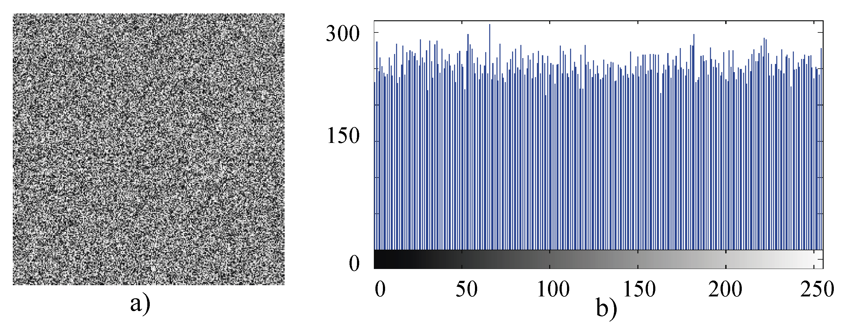
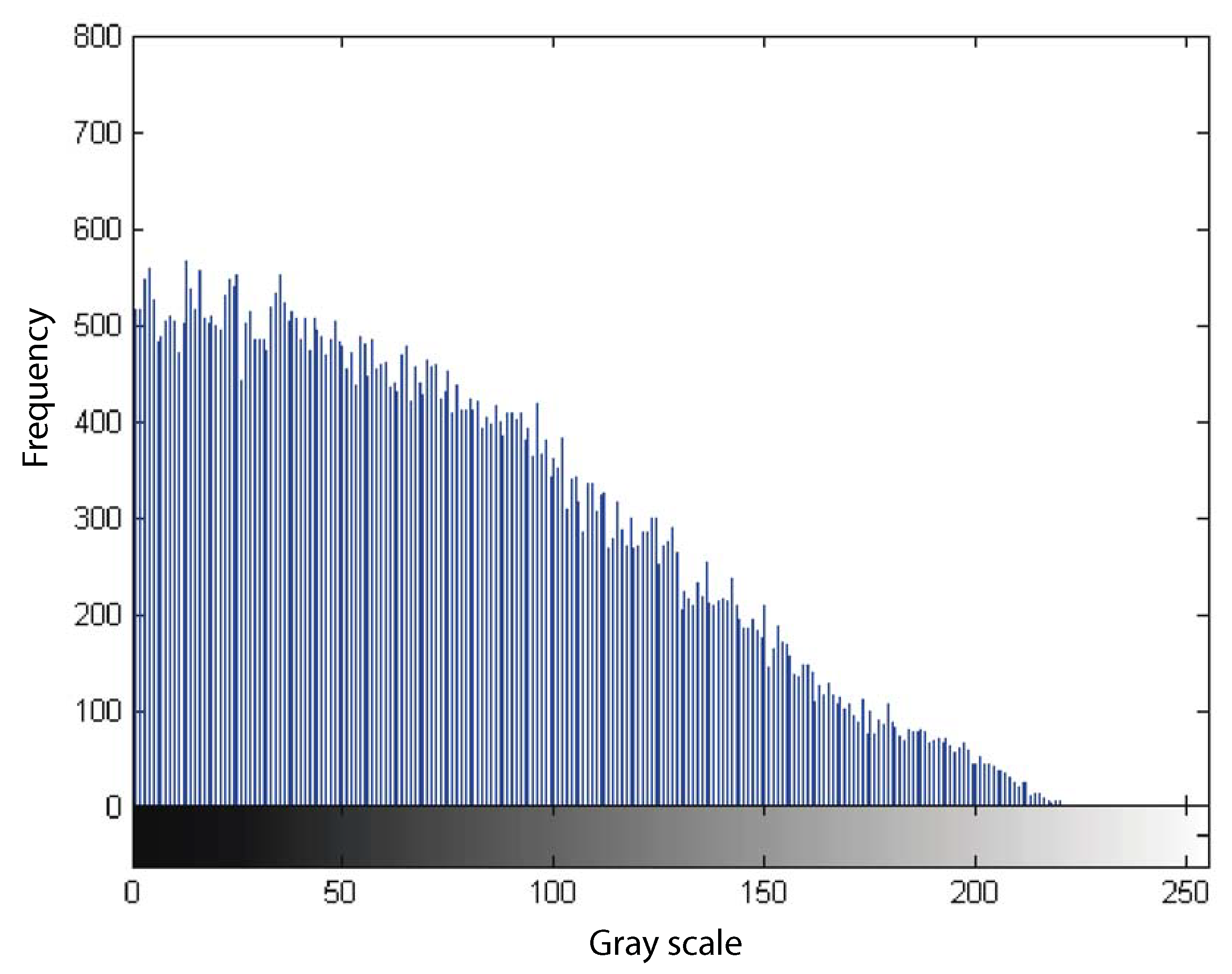
4.1.2. Information Entropy

The entropy H ( s ) is a criterion that shows the randomness of a source of pixels (s) [44] and to evaluate this value, the Equation (3) is used,
H ( s ) = n = 0 2 N 1 P ( s i ) × log 2 ( 1 P ( s i ) ) bits .
P ( s i ) represents the probability of the symbol s i , N is the number of bits representing the basic unit of the source s, 2 N are all the combinations of the basic unit. For a purely random source, we expect entropy of H ( s ) = N , so, if we consider images with completely random pixels in the 8-bit gray scale, their entropy H ( s ) must be 8.
Table 3 shows the values of H ( s ) related to the cryptograms, Lena showed in Figure 5d and Cameraman in Figure 5e. It can be observed that the results obtained from Cameraman’s entropy are slightly better than Lena’s image, because it is closer to the ideal value of 8, and according to [44], for an ideal random image the value of information entropy is 8. This confirms that the well-known Cameraman image is more complex than Lena’s image.
Using the Rössler map as an example, Table 4 shows the values of H ( s ) for the Lena RBG cryptogram showed in Figure 5f.
From Table 3 and Table 4, we can see that the H(S) entropy is very close to the ideal value, which is 8.

4.1.3. Differential Attacks

NPCR and UACI are statistical tests that show the percentage of the change rate and intensity of the pixels between two cryptograms respectively [45]. NPCR evaluates the percentage of the number of different pixels between two images and can be evaluated from Equation (4),
N P C R = i , j D ( i , j ) W × H × 100 % ,
where D ( i , j ) is a binary arrangement: D ( i , j ) = 0 , if C 1 ( i , j ) = C 2 ( i , j ) , D ( i , j ) = 1 , when C 1 ( i , j ) C 2 ( i , j ) , C 1 and C 2 are encrypted images (cryptogram) obtained with very similar keys. W and H define the size of the image under analysis [15,44].
UACI evaluates the average intensity of the differences between the two encrypted images C 1 and C 2 , which is calculated from the Equation (5).
U A C I = 1 W × H i , j | C 1 ( i , j ) C 2 ( i , j ) | 255 × 100 % ,
where C 1 , C 2 , W and H have the same meaning as in the Equation (4).
Table 5 and Table 6 show the percentages of NPCR and UACI obtained in this work. The ideal values of NPCR and UACI are 100 % and 33 . 7677 % respectively, which is why, in relation to the obtained results, there is evidence of the sensitivity of the system against differential attacks.

4.1.4. Correlation of Adjacent Pixels

The adjacent pixels of an image are highly correlated because the value of a pixel and the value of any of its adjacent pixels are very similar. The correlation of an image can be plotted and the coefficient between the values of −1 and 1 can also be evaluated, where 0 means a null correlation. An ideal cryptogram must have a correlation close to zero [46]. To evaluate the correlation presented by an image, at least two thousand pairs of adjacent pixels are taken either horizontally, vertically, or diagonally and the respective coefficient is calculated from Equation (6) [47].
r x y = c o v ( x , y ) D ( x ) D ( y ) ,
where D ( x ) is the variance, x and y denote the values in the gray scale of the image under analysis and c o v ( x , y ) is the covariance defined by Equation (7),
c o v ( x , y ) = 1 N i = 1 N ( x i E ( x ) ) ( y i E ( y ) ) .
For the experimental implementation of Equations (6) and (7), the numerical evaluation of E ( x ) and D ( x ) were calculated from Equations (8) and (9), respectively.
E ( x ) = 1 N i = 1 N x i ,
D ( x ) = 1 N i = 1 N ( x i E ( x ) ) ,
where E ( x ) is the average value of the gray levels of the pixels. In Table 7, Table 8 and Table 9, the results of the evaluation of the correlation coefficients ( r x y ) for horizontal, vertical and diagonal pixels, associated with each of the cryptograms shown in Figure 5d–f are presented, noticing that the values obtained are very close to the ideal value, i.e., are close to 0.

4.1.5. Quality of the Encryption Algorithm

The quality of the encryption algorithm is evaluated by means of three tests [48], the irregular deflection factor A S , C C correlation, and the maximum factor of deflection D. The irregular deflection factor is expressed as the deflection of the intensity of the pixels in the encrypted image ( E I ), with respect to those of the original image ( O I ). The deflection is obtained by calculating the matrix X, which represents the absolute value of the deflection between each value of the pixel before and after the encryption. For this case, the histogram of the differences like the one shown in Figure 7 is obtained and the average value D followed by S (absolute value of the difference of the values of the histogram minus D) is calculated.
Finally, the encryption quality parameter A S (sum of the S differences) is determined [48]. The steps to obtain A S are shown in the following equations:
X = I O I E ,
H = h i s t ( X ) ,
D = 1 256 i = 0 255 h i ,
S ( i ) = H ( i ) D ,
A S = i = 0 255 D ( i ) .
where O I is the original image, E I is the encrypted image; h i is the amplitude of the absolute differences, A S is the irregular deflection. For an image of N × M pixels the expected value is close to ( N × M ) / 2 [48]. In the third column of Table 10 and Table 11 the results of the A S for each chaotic system implemented in the FPGA are illustrated, it can be observed that in all cases the results are very close to the ideal value, thus, the results are competitive.
The C C correlation has the objective of measuring the degree of similarity between an original image and its encrypted image, which is calculated from Equation (15)
C C = c o n ( x , y ) ( σ x , σ y ) = i = 1 N ( x i E ( x ) ) ( y i E ( y ) ) i = 1 N ( x i E ( x ) ) 2 i = 1 N ( y i E ( y ) ) 2 ,
where E ( x ) is the average of the pixels in the image x and E ( y ) is the average of the pixels in the image y. A value close to zero is expected if there is no correlation. The results are illustrated in the second column of Table 10 and Table 11 for each implemented chaotic system in FPGA; it can be observed that the results are close to ideal value 0.
The maximum deflection factor D measures the quality of the encryption in terms of how it maximizes the deflection between the original and encrypted images and is calculated from Equation (16)
D = h 0 + h 255 2 + i = 1 254 h i ,
where h i the amplitude of the absolute differences and D is the maximum deflection factor. For an image of N × M pixels the expected value is close to the product N × M . In the first column of Table 10 and Table 11 the results of the D value are shown for each chaotic system implemented in the algorithm. It can be observed that in all cases the results are very close to the ideal value N × M .

4.1.6. Statistical Test NIST SP 800-22

In [19] 17 statistical tests are considered as a standard of the NIST SP 800-22; in its last revision in the year 2010, an average binary sequence of 1,000,000 bits and an error margin ( α ) of 0.01 are taken into account, and these values can be modified at the user’s discretion. According to the standard NIST SP 800-22, the results of the selected tests p value T, to be accepted, must have a value between the margin of error previously selected and the proportion, this last one is a result of the tests.
The CPRBG sequence proposed in this work is composed of 1000 sequences of 1,000,000 bits with an error margin of 0.01 and the Rössler chaotic system is tested as an example, the results obtained with the other maps are similar. Table 12 shows the results obtained, the first column refers to the names of 17 selected tests and the following show the values obtained for each of the chaotic states X 1 , X 2 , and X 3 . From the results obtained, it is concluded that the CPRBG when using the state X 2 and X 3 is really pseudo-random because pass all the tests.

5. Conclusions

An embedded chaotic cryptosystem of digital images with speech recognition as an external access key was implemented in FPGA. The cryptosystem uses several technologies: (i) a Spartan 3E-1600 FPGA from Xilinx; (ii) a 64-bit Raspberry Pi 3 single board computer; and (iii) a voice recognition chip (VRC) manufactured by the company Sunplus, make a robust system as a whole by contemplating several elements that prevent easy access to unauthorized intruders, such as, the recognition of the pre-established access key. The operability of the system as a whole based on the embedded algorithms that allow communication between the different technologies is demonstrated. It is verified that the algorithm proposed in this work for the CPRBG based on the implementation of the function m o d ( 255 ) in FPGA can be considered as a Truly Pseudo-Random Binary Generator defined under the SP 800-22 standard of NIST, the results are very competitive and reliable as a whole as to the quality of the encryption/decryption process. The security analysis confirms that our proposed cryptosystem is highly secure and robust against: key space, information entropy, differential attacks, correlation of adjacent pixels, quality of the encryption. In addition, the versatility of the system is verified in terms of using the same algorithm to encrypt or decrypt images under chaotic maps of different levels of complexity on images that can be taken in real time or those stored in memory.

Author Contributions

Funding acquisition, E.E.G.-G. and E.I.-G.; Investigation, E.R.-O., E.E.G.-G., E.I.-G., O.R.L.-B., A.F.-V., J.R.C.-V. and E.T.-C.; Methodology, E.I.-G.; Supervision, E.E.G.-G.; Writing: original draft, E.R.-O., O.R.L.-B. and A.F.-V.; Writing: review and editing, E.E.G.-G., E.I.-G., J.R.C.-V. and E.T.-C.

Funding

This work was supported by the research project approved at the 18th Internal Call for Research Projects by UABC, with number 485. The researchers E.R.O. and A.F.-V. were supported for his postgraduate studies at PhD level by CONACyT. Thanks to PRODEP (Professional Development Program for Professors) for supporting the new generations and for innovating the application of knowledge with the number 402/377/E.

Conflicts of Interest

The authors declare no conflict of interest. The founding sponsors had no role in the design of the study; in the collection, analyses, or interpretation of data; in the writing of the manuscript, or in the decision to publish the results.

References

  1. Liao, T.L.; Wan, P.Y.; Chien, P.C.; Liao, Y.C.; Wang, L.K.; Yan, J.J. Design of High-Security USB Flash Drives Based on Chaos Authentication. Electronics 2018, 7, 82. [Google Scholar] [CrossRef]
  2. Karimov, T.; Butusov, D.; Andreev, V.; Karimov, A.; Tutueva, A. Accurate Synchronization of Digital and Analog Chaotic Systems by Parameters Re-Identification. Electronics 2018, 7, 123. [Google Scholar] [CrossRef]
  3. Kaintura, A.; Dhaene, T.; Spina, D. Review of Polynomial Chaos-Based Methods for Uncertainty Quantification in Modern Integrated Circuits. Electronics 2018, 7, 30. [Google Scholar] [CrossRef]
  4. Carbajal-Gomez, V.; Tlelo-Cuautle, E.; Sanchez-Lopez, C.; Fernandez-Fernandez, F. PVT-Robust CMOS Programmable Chaotic Oscillator: Synchronization of Two 7-Scroll Attractors. Electronics 2018, 7, 252. [Google Scholar] [CrossRef]
  5. Farwa, S.; Muhammad, N.; Shah, T.; Ahmad, S. A Novel Image Encryption Based on Algebraic S-box and Arnold Transform. 3D Research 2017, 8, 1–14. [Google Scholar] [CrossRef]
  6. Bibi, N.; Farwa, S.; Muhammad, N.; Jahngir, A.; Usman, M. A novel encryption scheme for high-contrast image data in the Fresnelet domain. PLoS ONE 2018, 13, e0194343. [Google Scholar] [CrossRef] [PubMed]
  7. Muhammad, N.; Bibi, N. Digital image watermarking using partial pivoting lower and upper triangular decomposition into thewavelet domain. IET Image Process. 2015, 9, 795–803. [Google Scholar] [CrossRef]
  8. Muhammad, N.; Bibi, N.; Qasim, I.; Jahangir, A.; Mahmood, Z. Digital watermarking using Hall property image decomposition method. Pattern Anal. Appl. 2017, 21, 997–1012. [Google Scholar] [CrossRef]
  9. Muhammad, N.; Bibi, N.; Mahmood, Z.; Akram, T.; Naqvi, S. Reversible integer wavelet transform for blind image hiding method. PLoS ONE 2017, 12, e0176979. [Google Scholar] [CrossRef]
  10. Pecora, L.; Carroll, T. Synchronization in chaotic systems. Phys. Rev. Lett. 1990, 64, 821. [Google Scholar] [CrossRef]
  11. Alvarez, G.; Li, S. Some basic cryptographic requirements for chaos-based cryptosystems. Int. J. Bifurc. Chaos 2006, 16, 2129–2151. [Google Scholar] [CrossRef]
  12. Kocarev, L.; Jakimoski, G. Pseudorandom bits generated by chaotic maps. IEEE Trans. Circuits Syst. I Fundam. Theory Appl. 2003, 50, 123–126. [Google Scholar] [CrossRef]
  13. Cristina, D.; Radu, B.; Ciprian, R. A new pseudorandom bit generator using compounded chaotic tent maps. In Proceedings of the 9th International Conference on Communications (COMM), Bucharest, Romania, 21–23 June 2012; pp. 339–342. [Google Scholar]
  14. Addabbo, T.; Fort, A.; Rocchi, S.; Vignoli, V. Digitized chaos for pseudorandom number generation in cryptography. In Chaos-Based Cryptography; Springer: Berlin/Heidelberg, Germany, 2011; pp. 67–97. [Google Scholar]
  15. Wang, X.; Min, L.; Zhang, M. A generalized stability theorem for continuous chaos systems and design of pseudorandom number generator. In Proceedings of the 2015 11th International Conference on Computational Intelligence and Security (CIS), Shenzhen, China, 19–20 December 2015; pp. 375–380. [Google Scholar]
  16. Liu, L.; Miao, S.; Hu, H.; Deng, Y. Pseudorandom bit generator based on non-stationary logistic maps. IET Inf. Secur. 2016, 10, 87–94. [Google Scholar] [CrossRef]
  17. De la Fraga, L.; Torres Pérez, E.; Tlelo-Cuautle, E.; Mancillas-López, C. Hardware implementation of pseudo-random number generators based on chaotic maps. Nonlinear Dyn. 2017, 90, 1661–1670. [Google Scholar] [CrossRef]
  18. Farwa, S.; Shah, T.; Muhammad, N.; Bibi, N.; Jahangir, A.; Arshad, S. An Image Encryption Technique based on Chaotic S-Box and Arnold Transform. Int. J. Adv. Comput. Sci. Appl. 2017, 8, 360–364. [Google Scholar] [CrossRef]
  19. Rukhin, A.L.; Soto, J.; Nechvatal, J.R.; Smid, M.E.; Barker, E.B.; Leigh, S.D.; Levenson, M.; Vangel, M.; Banks, D.L.; Heckert, N.A. A Statistical Test Suite for Random and Pseudorandom Number Generators for Cryptographic Applications; NIST: Gaithersburg, MD, USA, 2010. [Google Scholar]
  20. Min, L.; Lan, X.; Hao, L.; Yang, X. A 6 dimensional chaotic generalized Synchronization system and design of pseudorandom number generator with application in image encryption. In Proceedings of the Tenth International Conference on Computational Intelligence and Security (CIS), Kunming, China, 15–16 November 2014; pp. 356–362. [Google Scholar]
  21. Volos, C.K. Chaotic random bit generator realized with a microcontroller. Comput. Model. 2013, 3, 115–136. [Google Scholar]
  22. Tanougast, C. Hardware implementation of chaos based cipher: Design of embedded systems for security applications. In Chaos-Based Cryptography; Springer: Berlin/Heidelberg, Germany, 2011; pp. 297–330. [Google Scholar]
  23. Qi, A.; Zhang, C.; Wang, H. A switched hyper chaotic system and its FPGA circuitry implementation. J. Electron. (China) 2011, 28, 383–388. [Google Scholar] [CrossRef]
  24. Tlelo-Cuautle, E.; Rangel-Magdaleno, J.; Pano-Azucena, A.; Obeso Rodéelo, P.; Nuñez Perez, J. FPGA realization of multi-scroll chaotic oscillators. Commun. Nonlinear Sci. Numer. Simul. 2015, 27, 66–80. [Google Scholar] [CrossRef]
  25. Azzaz, M.S.; Tanougast, C.; Sadoudi, S.; Dandache, A. New hardware cryptosystem based chaos for the secure real-time of embedded applications. In Proceedings of the 2011 IEEE Workshop on Signal Processing Systems (SiPS), Beirut, Lebanon, 4–7 October 2011; pp. 251–254. [Google Scholar]
  26. Mansingka, A.S.; Zidan, M.A.; Barakat, M.L.; Radwan, A.G.; Salama, K.N. Fully digital jerk-based chaotic oscillators for high throughput Pseudo-random number generators up to 8.77 gbits/s. Microelectron. J. 2013, 44, 744–752. [Google Scholar] [CrossRef]
  27. Fang, X.; Wang, Q.; Guyeux, C.; Bahi, J.M. FPGA acceleration of a pseudorandom number generator based on chaotic iterations. Inf. Secur. Appl. 2014, 19, 78–87. [Google Scholar] [CrossRef]
  28. Tlelo-Cuautle, E.; Pano-Azucena, A.; Rangel-Magdaleno, J.; Carbajal Gomez, V.; Rodriguez-Gomez, G. Generating a 50-scroll chaotic attractor at 66 MHz by using FPGAs. Nonlinear Dyn. 2016, 85, 2143–2157. [Google Scholar] [CrossRef]
  29. Tlelo-Cuautle, E.; Carbajal-Gómez, V.; Obeso-Rodelo, P.; Angel Magdanelo, J.; Nuñez Perez, J.C. FPGA realization of a chaotic communication system applied to image processing. Nonlinear Dyn. 2015, 82, 1879–1892. [Google Scholar] [CrossRef]
  30. Dabal, P.; Pelka, R. An efficient post-processing method for pipelined pseudo-random number generator in SoC-FPGA. In Proceedings of the 22nd International Conference Mixed Design of Integrated Circuits & Systems (MIXDES), Torun, Poland, 25–27 June 2015; pp. 607–611. [Google Scholar]
  31. Inzunza-Gonzalez, E.; Cruz-Hernandez, C. Double Hyperchaotic Encryption for Security in Biometric Systems. Nonlinear Dyn. Syst. Theory 2013, 13, 55–68. [Google Scholar]
  32. Mughal, B.; Sarif, M.; Muhammad, N. Bi-model processing for early detection of breast tumor in CAD system. Eur. Phys. J. Plus 2017, 132, 2–14. [Google Scholar] [CrossRef]
  33. Naqvi, S.; Akram, T.; Iqbal, S.; Haider, S.; Kamram, M.; Muhammad, N. A dynamically reconfigurable logic cell: From artificial neural networksto quantum-dot cellular automata. Appl. Nanosci. 2018, 8, 89–103. [Google Scholar] [CrossRef]
  34. Mughal, B.; Muhammad, N.; Sharif, M.; Rehman, A.; Saba, T. Removal of pectoral muscle based on topographic map and shape-shifting silhouette. BMC Cancer 2018, 18, 778. [Google Scholar] [CrossRef] [PubMed]
  35. Khan, M.; Akram, T.; Sharif, M.; Javed, M.; Muhammad, N. An implementation of optimized framework for action classification using multilayers neural network on selected fused features. Pattern Anal. Appl. 2018, 1–21. [Google Scholar] [CrossRef]
  36. Hénon, M. A two-dimensional mapping with a strange attractor. Commun. Math. Phys. 1976, 50, 69–77. [Google Scholar] [CrossRef]
  37. Kaplan, J.; Yorke, J. Functional Differential Equations and Approximation of Fixed Points. Lect. Notes Math. 1979, 730, 228. [Google Scholar]
  38. Grassberger, P. On the hausdorff dimension of fractal attractors. J. Stat. Phys. 1981, 26, 173–179. [Google Scholar] [CrossRef]
  39. Nusse, H.E.; Yorke, J.A.; Kostelich, E.J. Basins of attraction. In Dynamics: Numerical Explorations; Springer: New York, NY, USA, 1997; pp. 269–314. [Google Scholar]
  40. Rössler, O. An equation for hyper chaos. Phys. Lett. A 1979, 71, 155–157. [Google Scholar] [CrossRef]
  41. Liu, J.; Chen, J. The application of speech synthesis in car warning system. In The Proceedings of the Second International Conference on Communications, Signal Processing, and Systems; Springer: Cham, Switzerland, 2014; pp. 657–662. [Google Scholar]
  42. Behnia, S.; Akhshani, A.; Ahadpour, S.; Mahmodi, H.; Akhavan, A. A fast chaotic encryption scheme based on piecewise nonlinear chaotic maps. Phys. Lett. A 2007, 366, 391–396. [Google Scholar] [CrossRef]
  43. Shannon, C.E. A mathematical theory of communication. ACM SIGMOBILE Mob. Comput. Commun. 2001, 5, 3–55. [Google Scholar] [CrossRef]
  44. Mao, Y.Y.; Deng, Z.C. A new image encryption algorithm of input-output feedback based on multi-chaotic system. Appl. Mech. Mater. 2011, 40, 924–929. [Google Scholar] [CrossRef]
  45. Patidar, V.; Pareek, N.; Purohit, G.; Sud, K. A robust and secure chaotic standard map based pseudorandom permutation-substitution scheme for image encryption. Opt. Commun. 2011, 284, 4331–4339. [Google Scholar] [CrossRef]
  46. Fu, C.; Lin, B.; Miao, Y.; Liu, X.; Chen, J. A novel chaos-based bit-level permutation scheme for digital image encryption. Opt. Commun. 2011, 284, 5415–5423. [Google Scholar] [CrossRef]
  47. Chen, G.; Mao, Y.; Chui, C.K. A symmetric image encryption scheme based on 3D chaotic cat maps. Solitons Fractals 2004, 21, 749–761. [Google Scholar] [CrossRef]
  48. Elkamchouchi, H.; Makar, M. Measuring encryption quality for bitmap images encrypted with rijndael and kamkar block ciphers. In Proceedings of the Twenty-Second National Radio Science Conference (NRSC 2005), Cairo, Egypt, 15–17 March 2005; pp. 277–284. [Google Scholar]
Figure 1. Block diagram of the proposed embedded cryptosystem.
Electronics 07 00414 g001
Figure 2. Experimental arrangement of the proposed embedded cryptosystem.
Electronics 07 00414 g002
Figure 3. Block diagram of the main control subsystem implemented in FPGA Spartan 3E.
Electronics 07 00414 g003
Figure 4. Operation m o d ( 255 ) implemented in FPGA by using Simulink with SysGen blocks.
Electronics 07 00414 g004
Figure 5. Images used to perform security analysis tests. (a) Lena image 255 × 255 gray scale pixels; (b) Cameraman Image 512 × 512 gray scale pixels; (c) Image of Lena RGB 512 × 512 pixels; (df), their respective cryptogram.
Electronics 07 00414 g005
Figure 6. Image recovered from Lena when using a slightly different key (Sensitivity Analysis). (a) Recovered image; (b) Histogram of the recovered image.
Electronics 07 00414 g006
Figure 7. Histogram of the differences.
Electronics 07 00414 g007
Table 1. Key space by using different chaotic map.
Chaotic MapMantissaParameters and Initial ConditionsKey Space
Hénon24Q204 2 159
Rössler24Q3010 2 497
Tinkerbell24Q206 2 236
Logistics24Q206 2 238
Karplan-Yorke24Q303 2 149
Table 2. Sensitivity of the Rössler system implemented in FPGA.
Theoretical (Simulate) Initial Condition X 1 ( 0 ) X 1 ( 0 ) in the FPGA
X 1 ( 0 ) = 0.1 ExperimentalMinimum change
0.100000000000364 0.099999046326047
Table 3. Information entropy H ( s ) of the Lena and Cameraman cryptograms.
Chaotic SystemLenaCameraman
Hénon7.997282247.99927416
Tinkerbell7.997095787.99929761
Karplan-Yorke7.996960757.9989076
Logistics7.997393037.99928301
Rössler7.997569557.99870848
Table 4. Entropy of the Lena RBG cryptogram.
ColorEntropy
Red7.99912746
Green7.99920835
Blue7.999218050
Table 5. NPCR and UACI differential attacks.
Chaotic SystemLenaCameraman
NPCR%UACI%NPCR%UACI%
Hénon 99.6307373 33.5661825 99.60212708 33.52865032
Tinkerbell 99.5758057 33.3647365 99.61242676 33.37476543
Karplan-Yorke 99.6002197 33.5527128 99.61128235 33.38566649
Logistic 2D 99.5773315 33.5271439 99.59602356 33.44978482
Rössler 99.6200562 33.4577912 99.61204529 33.56798209
Table 6. NPCR and UACI differential attacks of Lena RGB encrypted using Rössler map.
Color RGBNPCR%UACI%
Red 99.61738586 33.58308979
Green 99.61967468 33.57611413
Blue 99.62005615 33.54349622
Table 7. Correlation coefficients of Lena’s cryptogram.
SystemHorizontalVerticalDiagonal
Hénon 1.1210 × 10 3 5.8573 × 10 2 3.2015 × 10 2
Tinkerbell 1.0641 × 10 1 1.7812 × 10 2 9.4017 × 10 2
Karplan-Yorke 2.2356 × 10 2 1.1600 × 10 2 3.3231 × 10 2
Logistic 2D 5.4137 × 10 2 4.3078 × 10 2 2.3518 × 10 2
Rössler 9.8539 × 10 2 7.4748 × 10 2 5.9399 × 10 2
Table 8. Correlation coefficients of the Cameraman’s cryptogram.
SystemHorizontalVerticalDiagonal
Hénon 3.3808 × 10 2 3.5779 × 10 2 3.5536 × 10 2
Tinkerbell 1.2448 × 10 1 3.2571 × 10 2 3.1768 × 10 2
Karplan-Yorke 8.0906 × 10 2 5.2241 × 10 2 1.5412 × 10 3
Logistic 2D 9.9549 × 10 2 8.7098 × 10 2 1.1875 × 10 2
Rössler 4.9263 × 10 3 9.2114 × 10 2 3.7723 × 10 2
Table 9. Correlation coefficients of the Lena RGB cryptogram using Rössler map.
CorrelationRedGreenBlue
Horizontal 18.6062 × 10 3 12.2641 × 10 3 22.7746 × 10 3
Vertical 43.6481 × 10 3 17.8192 × 10 3 94.725 × 10 3
Diagonal 44.3792 × 10 3 18.6089 × 10 3 68.8857 × 10 3
Table 10. Quality of the encryption algorithm by testing Lena’s cryptogram.
Chaotic SystemMaximum D CC CorrelationIrregular AS
Hénon 65 , 399 0.00908234 44 , 804
Tinkerbell 65 , 390.5 0.004472406 44 , 826
Karplan-Yorke 65 , 414.5 0.000286007 45 , 094
Logistic 2D 65 , 394.5 0.002105741 45 , 078
Rössler 65 , 408.5 0.001003561 45 , 000
Table 11. Encryption quality algorithm by using the Cameraman cryptogram.
Chaotic SystemMaximum D CC CorrelationIrregular AS
Hénon 261 , 606 0.000674241 157 , 706
Tinkerbell 261 , 607 0.001918371 158 , 116
Karplan-Yorke 261 , 634.5 0.005342149 159 , 376
Logistic 2D 261 , 610 0.000764522 158 , 266
Rössler 261 , 591 0.001736202 157 , 352
Table 12. Results of the NIST SP 800-22 test to the CPRBG by using Rössler map.
Sequence Test X 1 X 2 X 3
p Value TProportionp Value TProportionp Value TProportion
Frequency0.9357160.990.0909361.00.5341461.0
Block Frequency0.5141240.980.0351741.00.2896671.0
Cumulative Sums up0.5955491.00.5544201.00.0805191.0
Cumulative Sums down0.4749860.980.4749861.00.4011991.0
Runs0.0711771.00.7981391.00.5544200.99
Longest Run0.5141240.970.6993130.990.2622490.99
Rank0.4943920.990.2133091.00.2896671.0
FTT0.1087910.980.1718671.00.0628210.99
Non Overlapping Template0.5141240.990.7791881.00.9357161.0
Overlapping Template0.5749031.00.8165371.00.3041261.0
Universal0.3838271.00.6579331.00.4943921.0
Approximate Entropy0.0308061.00.2492840.990.6163051.0
Random excursions0.5544201.00.0021751.00.6717791.0
Random excursion variant0.1453261.00.3924561.00.0602391.0
Serial 10.6371191.00.2248211.00.8513831.0
Serial 20.3345381.00.9642951.00.1087911.0
Linear Complexity0.4749861.00.8831711.00.2896671.0

