Adaptive Thermal-Aware Routing Protocol for Wireless Body Area Network


1
Department of Computer Engineering, Jeju National University, Jejusi 63243, Jeju Special Self-Governing Provience, Korea
2
Department of Computer Science, Capital University of Science and Technology, Islamabad 44000, Pakistan
3
Department of Computer Science, University of Engineering and Technology, Taxila 47080, Pakistan
*
Author to whom correspondence should be addressed.
Electronics 2019, 8(1), 47; https://doi.org/10.3390/electronics8010047
Submission received: 1 November 2018
/
Revised: 11 December 2018
/
Accepted: 12 December 2018
/
Published: 1 January 2019
(This article belongs to the Section Networks)
Abstract
:The recent advancement in information technology and evolving of the (IoT) shifted the traditional medical approach to patient-oriented approach (e.g., Telemedicine/Telemonitoring). IoT permits several services including sensing, processing and communicating information with physical and bio-medical constraints. Wireless Body Area Network (WBAN) handles the issues pertaining to the medical purposes in the form of sensor nodes and connected network. The WBAN takes human physiological data as an input to subsequently monitor the patient conditions that are transferred to other IoT components for analysis. Such monitoring and analysis demand a cohesive routing approach to ensure the safe and in-time transfer of data. The temperature rise of bio-medical sensor nodes makes the entire routing operation very crucial because the temperature of implanted nodes rises and ultimately damages body tissues. This needs dispersion in data transmission among different nodes by opting various available routes while avoiding temperature rise. In this paper, we present Adaptive Thermal-Aware Routing algorithm for WBAN. The ATAR is designed to overcome the temperature rise issue of implanted bio-medical sensors nodes. The new protocol is based on Multi-Ring Routing approach to find an alternative route in the case of increasing temperature. The simulation results indicate that proposed protocol is more efficient in terms of temperature rise and throughput than existing approaches.
1. Introduction
Internet-of-Things (IoT) is the network of interrelated physical objects embedded with electronic, software devices and wearable sensors that efficiently collect and exchange data with each other over the network [1,2,3,4,5,6]. The emerging IoT technology plays a consequential role in various walks of life e.g., business, transport, education, etc., as well as healthcare system by providing health’s facilities to the patient at low cost on his doorstep [7]. These IoT devices are harnessed to connect the patients and doctors around the world through Internet [8].
In many cases, health is one of the most important challenges and, therefore, the World Health Organization (WHO) constitutions emphasize for most people to attain health facilities. In the current era, excessive rise of various chronic and acute diseases has put the life of many people at an immense danger, which has consequently caused many to maintain good health. A large number of doctors, nurses and allied staff constantly monitor the health of a patient [9]. Patients with chronic diseases (i.e., diabetes, heart stock, high blood pressure, etc.) are required to be monitored on a regular basis. It is a requisite to monitor the vital signs of patients suffering from these diseases on a daily basis, which results in expenditure of huge amount of money. Due to the increase in the number of patients, more hospitals, doctors and greater amount of time is required to deal with them [9]. Moreover, to attain medical procedures, physical presence of patients in the hospitals is also important, which might affect the activities of daily life.
As the health factor is of concern, many healthcare organizations (e.g., WHO [10]) emphasize on the use of IT technology (i.e., Wireless Body Area Network (WBAN) [11], Telemedicine [10]). WHO reported that chronic diseases like cardiovascular and heart diseases will be one of the main causes of deaths all over the world by the year 2030 [11]. An analysis shows that the current health-care providing services to patients are insufficient and appropriate even in urban areas of many countries. Moreover, patients with multiple health problems are rapidly increasing the cost of the health-care system [10]. Health-care organizations (HIPAA (Health Insurance Portability and Accountability), WHO, Health Information Technology for Economic and Clinical Health (HITECH)) [10,12,13] make use of advanced information technology techniques and communication gadgets to efficiently deal with the complex medical issues by maintaining low costs. It is possible to utilize the latest technology for early identification and precaution of potential diseases that have a high probability to infect the patients, e.g., Telemedicine and E-health, etc. [10,14,15,16,17].
Telemonitoring [15] plays a significant role in early remote monitoring, disease detection, preventions and knowledge-based feedback from medical professionals [17,18]. Electronic prescription, Short Message Alerts (SMS) and emails are a part of patient monitoring systems that result in reliability and it diminishes the hurdles for patients to visit medical centers and recede the expenditure cost for hospitals or medical centers [19]. Nowadays, prevention of in-hospital morbidity and mortality is potentially a matter of prime interest [20]. The studies revealed that on-time diagnosis and treatment of severe diseases lessen the amount of patients at Intensive Care Units (ICUs) [21]. Contemplating all associated advantages, Telemonitoring is deemed as a paramount area of research because it renders the advanced technology to turn raw data into valuable information. It is recounted that an ideal Telemonitoring system must be capable of the (1) collection of correct medical data through bio-medical sensors, (2) conclusion and analysis on available physiological (vital sign) data (3) decision of appropriate actions with physician advice on the basis of composed information.
For collection of vital signs of patients, healthcare applications with emergence of biomedical sensor devices turned the technology into WBAN [18,22]. WBAN is an extended form of Wireless Sensor Networks (WSN) that is implemented for specific medical purposes by incorporating various networks and wireless tools that ensure distant healthcare monitoring. Hence, the implementation of WBAN results in better quality of life through timely detection and by taking proactive measures. Due to the hustle of daily lives, many people do not prefer to stay in hospitals for continuous monitoring. Monitoring of multiple patients in a real-time environment is one of the significant applications of WBAN [23]. The fundamental objective of WBAN is to get human physiological or vital sign data (i.e., temperature, glucose level, heart rate, etc.) from patient(s) for continuous monitoring [22] that ultimately demands an efficient routing mechanism. The designing of efficient and reliable routing protocols is a challenging job for WBAN due to its distinct features and limitations including overheating and energy depletion of embedded sensor nodes. The energy consumption and heat-rise affect the stability of a network and, hence, WBAN data is transmitted through various paths. The study is aimed to improving the network lifetime and WBAN network performance through efficient routing while managing temperature rise and decreasing the energy consumption.
Over the years, various WBAN routing protocols have been proposed in the literature. These protocols could be segregated into six categories, i.e., Thermal-aware routing protocols, Energy-Aware based routing protocols, QoS-aware based routing protocols, Postural-movement-based routing protocols, Cluster-based routing protocols and Cross-layered routing protocols [24]. This study focuses on the thermal-aware scheme because the prime focus of the proposed study is associated towards the introduction of novice WBAN routing protocol which is thermal-aware routing protocol. The contemporary thermal-aware routing protocols include TARA [25], LTR [26], ALTR [26], LTRT [27], HPR [28], RAIN [29], TSHR [30], M-ATTEMPT [31], TMQoS [32], RE-Attempt [33], [34], TLQoS [35], DRC [36], TTRP [37], TRPL [38] etc.
The “Thermal-Aware Routing Algorithm (TARA)”, is proposed to decrease the chances of temperature of the implanted bio-medical sensor in the body of a human. The TARA algorithm ensures the equal temperature diffusion between all the nodes via contemplating temperature. However there are some limitations of TARA, such as network lifetime, packet drop and reliable transmission. The Adaptive Least Temperature Routing (ALTR) protocol is presented to overcome the problem faced in TARA. In ALTR instead of discarding the packet after it exceeds the threshold value, it works as Shortest Hop Routing (SHR) to transfer the packet to the destination. However, it only considers average temperature metrics and less Network lifetime and high end-to-end delay.
Several mechanisms discussed above [25,26,27,28,39,40] have been adopted to handle the problem of temperature rise when data is transmitted among the nodes as well as a sink node in an IoT-based WBAN system. To the best of our knowledge, these techniques do not focus on the overall rise of temperature in the entire network and temperature rise in the forwarding node. The reliable and quick transmission of data consuming low-temperature rise is highly important in WBAN. This study presents a thermal-aware routing protocol for WBANs, which aims at the uniform diffusion of load among sensors nodes in term of temperature rise. The proposed thermal-aware WBAN routing protocol known as Adaptive Thermal-Aware Routing (ATAR). The ATAR addresses the problem of temperature rise and decreased data transmission while increasing network life.
2. Related Work
In WBAN, routing is a crucial process due to restricted available resources, i.e., less computational power, energy source and memory [28]. In WBAN, the usage of energy consumption is directly proportional to the Radio Frequency (RF) at sensor nodes’ physical layer. Moreover, the sensor nodes’ residual energy could be enhanced via MAC protocols by controlling the RF part’s duty cycle. Several studies exist in the literature regarding energy efficient protocols in WSN [41,42]. The protocols of MAC and physical layer enhance the network communication irrespective of the certitude. In the contemporary studies do not handle the necessities like addressing schemes, end-to-end packet delivery and determination methods of routes. Probably, these issues could be pretty much handled with assistance of the network layer. Moreover, network layer routing protocol plays a pivotal role when it comes to conserve the energy and temperature of WBAN sensor nodes [43]. Though, the subset of WSN is WBAN but WBAN is different than WSN in terms of the specifications and nature due to which the transformation of coherent WBAN routing protocol demands more attention than WSN (Wireless Sensor Network).
Some aspects of WBAN demand special attention, such as limited bandwidth (because of duty cycle mechanism or interference), nature of heterogeneous network (because of specific physiological data), consumption of energy (because of higher rate of transmission), increased temperature (because of high number of transmissions), coverage area (because of small range of range), Quality of Service (QoS—because of priority-based data) and mobility (because of postural movements) [44].
The most quintessential factor among all depicted issues is the increased temperature of sensor nodes that negatively affects the performance of WBAN. Such high temperature is reported due to energy consumption and assimilated radiation by the antenna that result in damaging the heat sensitive areas of the body [45]. Moreover, high temperature can also hit the body tissues around the sensor nodes [26]. All these stated issues demand a significant research to propose a routing algorithm for WBAN to avert the damage of body tissues that occur due to rise of node’s temperature. Consequently, insightful routing algorithm that contemplates temperature rise can positively affect the life span of a network.
Taxonomy of Routing Protocols in WBAN
Over the years, a lot of WBAN routing protocols has been proposed in the literature. These protocols could be segregated into five categories, i.e., Thermal-aware routing protocols, Energy-Aware based routing protocols, QoS-aware based routing protocols, Postural-movement-based routing protocols, Cluster-based routing protocols and Cross-layered routing protocols [46]. The overview of all these protocols is presented in Figure 1.
The sensor nodes of WBAN are embedded and both produce electrical and magnetic fields during the transmission [25]. This issue can result in absorption of radiation and increased heat in the human body that leads to harm of sensitive organs by the minute temperature rise. For instance, lens contraction gets effected due to lack of blood flow occurred because of temperature rise of a node [16]. In [45] a Specific Absorption Rate (SAR) is introduced as an indicator at which the energy is immersed from the body of human when it gets revealed to a radio frequency (RF) electromagnetic field. The formula to calculate SAR is presented in Equation (1).
where is electrical conductivity of body tissue, E is induced electric field by radiation, is density of body tissues, W and Kg represent the units of watts per kilogram. Primarily, SAR defines the upper limit of the transmitting power. Therefore, WBAN routing protocols should be designed to reduce the radiation emission to transmit data. Considering safety, radiation absorption is required to be reduced either by controlling SAR or using an appropriate routing protocol.
Bag et al. in [27], a model is proposed to handle the upshot occurred during the communication by the bio-medical sensors on human body. In this study, a rate controlled recommendation model for WBAN transformation is presented based on the observation. Thermal-aware routing techniques are significant to discuss while designing the Intra-WBAN. To evade the temperature rise and radiation that cause harm to the human body, diversified routing protocols related to thermal-aware have been introduced in the literature. The contemporary thermal-aware routing protocols discussed in the literature include, TARA [25], LTR [26], ALTR [26], LTRT [27], HPR [28], RAIN [29], TSHR [30], M-ATTEMPT [31], TMQoS [32], RE-Attempt [33], [34], TLQoS [35], DRC [36], TTRP [37], TRPL [38].
The first temperature sensitive routing algorithm i.e., Thermal-Aware Routing Algorithm (TARA) is presented in [25], Tang et al. The proposed algorithm aims to reduce the possibility of temperature rise of the implanted bio-medical sensor in the human body. TARA defined the overheated nodes as hotspots and routes away the data from these nodes during communication. The author defined the Temperature Increase Potential (TIP) to calculate the temperature rise of a node on the basis of SAR. During data transmission, each node observes the communication of neighboring nodes by counting the packets, calculating communication radiation and power consumption to evaluate the present temperature of nodes. This algorithm does not involve a node in data transmission when its temperature rises above the defined threshold value. TARA enforces the equal temperature dissemination among all the nodes within the network by considering temperature as a metric. As the temperature is the only metric, TARA has to face the issues such as network lifetime, packet drop and reliable transmission.
Least Temperature Rise (LTR) is an enhanced version of TARA to address the overheating of implanted sensors and delay. In LTR is proposed in [26], the selection of the next hop is based on the temperature of neighboring nodes and the node with least temperature is selected as a next hop. To avoid the bandwidth consumption, predefined MAX_HOP limit is defined in algorithm and when a packet exceeds that limit it is discarded. Previously visited lowest temperature node is saved in the list to avoid loop in the network. Loops are avoided by maintaining a list in the packet with the recently visited nodes.
Adaptive Least Temperature Routing (ALTR) protocol [26] overcomes the problem faced in LTR. The approach of ALTR is similar to LTR with the variation changing MAX_HOP by MAX_HOP_ADAPTIVE. In ALTR, instead of discarding the packet after it exceeds the threshold value of MAX_HOP_ADAPTIVE, it works as Shortest Hop Algorithm (SHA) to transfer the packet to the destination.
Least Total Route Temperature (LTRT) [27] is the combination of LTR and shortest path routing [40]. In LTRT, the total route is selected from source to destination on the basis of temperature. LTRT selects a least temperature route to forward data instead of only considering the next hop. The temperature of sensors is transformed into graph weights and minimum temperature routes are obtained using Dijkstra’s algorithm. During the data transmission, the temperature of a sensor node rises by one unit upon receiving or transmitting data and decreases by one unit when it is inactive in transmission (defined time interval). In LTRT, hop count per packet and packet drop is decreased. It also aids in reducing overheating of sensors but the shortcoming in LTRT is that it requires to know the temperature of all sensors in the network. Moreover, energy consumption and overhead of acquiring the record of all temperatures is not measured.
Hotspot Preventing Routing (HPR) [28] is another thermal-aware routing protocol that addresses delay during data transmission. It includes two phases i.e., setup phase and routing phase to avoid the delay and forming of hotspots in the network. In the first phase, all the sensor nodes exchange information about the shortest route and temperature of the nodes to build their routing tables. In routing phase, each node transfers data using the shortest available route in the routing table and maintains a hop-count. If the value exceeded than the threshold value of hop-count, the packet is discarded. If neighboring node is the destination node then the packet would be directly sent to it; otherwise, it chooses next hop from the shortest path based on temperature (equal or less than the threshold value). The threshold temperature of a sensor node is obtained by taking the average temperature of the neighboring nodes (including the temperature of sending node itself). In this approach, all nodes compute the threshold value of temperature on the basis of the temperature of its neighboring nodes and the temperature of the node itself, however, in other algorithms this value is predefined.
Bag et al. in [29] presented the goal of Routing Algorithm for Network of Homogeneous and ID-Less Bio-Medical Sensor Nodes (RAIN) is to decrease the average temperature rise and average power consumption of sensor nodes. It constitutes three phases i.e., setup phase, routing phase and status update phase. In the setup phase, temporary IDs are random, usable for its operational life and ID ‘zero’ is kept for the sink node. All nodes broadcast their IDs using hello packet. In the routing phase, a packet ID [N, T and R] is forwarded towards the destination, where N is the ID of the sensor node, T indicates the time at which the data packet is generated at the sending node and R is any random number. Loops are avoided by maintaining a hop-count with every packet and if the hop-count of the packet exceeds the threshold value of , then it is discarded. The nodes also avoid retransmission by maintaining the list of the packets IDs and a data packet is dropped if its ID is previously resides in that list. Every node knows the temperature of neighboring nodes by observing their communication actions. The packet is forwarded directly if the destination is one of the neighboring nodes otherwise it is forwarded to the neighbor node using probability which is inversely proportional to its temperature. In status update phase, the sink notifies all its neighboring nodes upon receiving any data packet by sending the packet’s ID to decrease the power consumption.
Shortest Hop Routing (SHR) is used to transfer the packet to the destination. However, it only considers average temperature metrics and having less Network lifetime and high end-to-end delay. Thermal-aware shortest hop routing protocol diminishes the overheating without influencing the packet delivery proportion, delay and power utilization of bio-restorative sensor hubs. Tabandeh et al. in [30] claimed that TSHR is optimal for those applications that have high priority data to exchange the packets to the destination. The copy of transmission packet is additionally considered in TSHR. It incorporates two stages: setup stage and routing stage. In setup stage, routing tables are created while in routing stage every node transmits the packets to the destination on the basis of the shortest path.
Huang et al. in [47] proposed a technique in which each sensor node is placed in different ring level. The ring level depicts the distance of each sensor node from the destination in the form of hop-count.
Abbas et al. in [31], proposed an energy efficient and thermal-aware routing protocol for WBAN to diminish the temperature of nodes. In addition to diminish the delay for the critical data by utilizing heterogeneous bio-therapeutic sensor nodes MATTEMPT involves four stages that are initialization stage, routing stage, scheduling stage and data transmission stage. In initialization stage, all nodes broadcast the hello packet, while in routing stage, courses with fewer hop counts are chosen within the available routes based on the temperature and energy metrics. The sink nodes make a Time Division Multiple Access (TDMA) plan for all root nodes in the scheduling stage, while the root nodes send their data to the sink hub amid the data transmission stage.
TMQoS is a thermal-aware multi-constrained intrabody routing protocol. The basic objective of this protocol is to keep the temperature of node at an adequate level. Hassan et al. in [32], proposed TMQoS, which is a proactive routing protocol that builds ongoing routing table which includes multiple shortest path routes. Beacon packet is used to exchange the information between sensor nodes for the formation and maintenance of routing table. The beacon packet is received by neighboring nodes through mac receiver module. Routing table constructor module is used for formation and maintenance of routing table in term of hop-count, delay and temperature value. It also has hotspot avoidance mechanism that keeps the packet away from hotspot area.
Reliability Enhanced-Adaptive Threshold-based Thermal-aware Energy-Efficient Multi-hop Protocol (RE-ATTEMPT) is a thermal and energy efficient routing protocol. Javaid et al. [33] presented that sink is placed between the nodes and nodes are sorted in descending order in term of data rate. The higher data rate node is placed where mobility is less and low data rate nodes are placed at mobility area of human body. This protocol uses direct communication for critical data and multi-hop communication for non-critical data. The protocol is divided into five phases: initialization phase, routing phase, scheduling phase and data transmission phase. The initialization phase is responsible for calculating the distance of nodes from sink node in the form of hop-count by broadcasting “Hello Message”. In this phase, all nodes are aware of their neighboring nodes, available routes and distance from sink. The routing phase is responsible for selecting an efficient route with less hop-count. In routing phase, critical data is directly sent to sink using direct communication while normal data is sent using multi-hop communication. In scheduling phase, time slot is assigned to sink and root nodes for communication of data. The root and sink nodes communicate within their assigned time slot. The last phase is data transmission phase wherein data is sent to sink node within their allocated time slot.
Rafatkhan et al. in [34] Multi-hop Routing Protocol is a thermal and energy efficient routing protocol. The protocol is divided into four phases including initialization, routing, scheduling and data transmission phase. The initialization phase is responsible for calculating distance of nodes from sink node by broadcasting “Hello Message”. The routing phase is responsible to send data to the medical server. If Home-Signal is received then one of the implanted nodes in the human will establish a link with routing table of the home node. In this way, a direct link is used to send the data from sink node to medical server. In the direct link, there is no energy restriction because critical data is sent over the selected link. If Home-Signal is not received then routing table formed from implanted nodes and multi-hop link get established for communication of data. This phase is also responsible for hotspot avoidance. In scheduling phase, time slot is assigned to sink and root nodes for communication of data. The root and sink nodes communicate within their assigned time slot. The last phase is data transmission phase wherein data is sent to sink node in their allocated time slot.
Thermal-aware localized QoS routing protocol (TLQoS) is a thermal-aware routing protocol which aims to address the required QoS demand of implanted bio-medical sensor in a human body. Monowar et al. in [35] presented the temperature of the node at an acceptable level to avoid heating or damaging of tissue. The protocol also prevents loop formation during communication and avoid unnecessary routes with a large number of hop from sink to control delay in the network. The localized approach is used for selecting suitable forwarder nodes among all neighboring nodes in a routing table. Monowar et al. [36] introduced an integrated rate control technique which ultimately aims to decrease the thermal effect of the implanted bio-medical sensor node and avoid congestion during communication between nodes.
Trust and Thermal-Aware Routing Protocol (TTRP) is another thermal-aware routing protocol which provides trusted and hotspot free network communication between the implanted bio-medical sensor nodes. Kumar et al. in [37] stated that the communication is protected from malicious and faulty nodes within or outside the network. The TTRP is divided into three phases: trust estimation phase, route discovery phase and route maintenance phase. The trust estimation phase is further divided into two sub-phases: direct trust and indirect trust. The trust estimation phase is responsible for evaluating the trustiness of intermediate nodes. The route discovery phase is responsible for selecting trustworthy and hotspot free node route for communication in the network. In route maintenance phase, if the node becomes hotspot during communication inactive route then route maintenance phase re-initiates the route discovery phase.
The self-healing thermal-aware RPL routing protocol is a self-adaptive routing protocol. In this protocol, if the node is marked as a hotspot node, then the node itself decides the efficient path for communication of data. The selection of efficient path is based on low temperature and low power metrics. In [38] the protocol work on IPv6 routing protocol for low power and lossy networks (RPL).
In Multipath ring routing (MRRP) [47], multiple paths are constructed to the destination to avoid congestion in the network. The protocol is divided into two phases: Multipath construction phase and Data transmission phase. In Multipath construction phase, a setup request packet is sent by the sink to all its neighboring nodes with ring level 0. Nodes which received packet will update its ring level by incrementing its value to 1 in it and broadcast the packet. The main aim of this phase is to organize the sensor nodes in the form of ring level. At the end of this phase, each node is assigned a ring level value and these nodes are separated according to their ring level value. In data transmission phase, each node is arranged according to their assigned ring level value. The sensor node sends the packet, broadcasts the packet to its neighboring node and the process continues until the packet is reached to the sink node.
Ordinarily, the little size of the battery in WBAN suggests that the capacity of the battery is low with little energy. Different schemes have been utilized to utilize power eruditely for the broadened life of remote systems (wireless network). Some power sparing schemes maintain a strategic distance from repetitive retransmissions, diminish the frequency of sending system control messages, lessening the size of message headers and utilizing the standby or sleep mode when conceivable [48]. Among the various difficulties of WBAN, energy utilization is an essentially vital long-term arrangement of WBANs, which is elaborated in various studies (ESR [14,15,16,17,23]). Here we shed a light on some of the energy-aware routing protocols including SIMPLE [49], Co-CEStat [50], RSSI [51], MEPF [52], DARE [53] and ESR [54].
The routing algorithm of QoS- aware are modular based and use various modules for different types of QoS metrics. The complexity and synchronization of the modules make it a challengeable task to design a QoS protocols. To provide QoS in WBAN, routing demands significant consideration as the patient’s data (normal or critical) should be transmitted to medical server efficiently and reliably. Broadly, the QoS routing protocols can be classified into reliability-based routing and delay-tolerant based protocols. The reliability-based routing does not consider delay and ensures throughput. The delay-tolerant based routing protocols guarantee in-time delivery of packets. Some of the important QoS-aware routing protocols are RL-QRP [55], LOCALMOR [56], DMQoS [57], EPR [53], QPRD [58] and QPRR [59] etc.
The third routing class of WBAN is cluster-based routing that is known as an appropriate protocol for increasing the lifespan of a network by reducing energy consumption. In this approach, WBAN network is divided into clusters and each cluster chooses Cluster Head (CH) that is responsible for communication to the base station to minimize the energy consumption of the other sensing nodes. The responsibilities of a CH include collecting, aggregating and forwarding of data. The two main cluster based WBAN routing protocols are Hybrid Indirect Transmissions (HIT) [60] and Anybody [61].
In WBAN topology the communication among the nodes frequently come across with the issues of disconnection and partitioning due to postural movements of the human body. Various studies have been conducted to resolve this issue and a cost function is defined in WBAN, that is updated at intervals. These protocols send packet with least cost on the basis of path selection from bio-medical sensor to base station. The routing protocols based on postural movements are postural-based routing protocol Probabilistic Routing (PRPLC) [62], On-Body Store and Flood Routing (OBSFR) [63], Dynamic Postural Partitioning (DVRPLC) [64], opportunistic routing protocol [65] and Energy Efficient Thermal and Power Aware Routing (ETPA) [66].
A Cross-layered routing protocol is the fifth class of WBAN routing. The Cross-layered scheme improves the synchronization between the layers without disturbing the main functions of the layers. The research community remained interested in the areas related to WSN because of its effective implementation in WSN. These protocols contribute in improving the performance of the network by addressing the challenges and issues faced in network and MAC layers simultaneously. The routing protocols based on cross-layered routing protocols are Wireless Autonomous Spanning Tree Protocol (WASP) [67], Cascading Information Retrieval by Controlling Access with Dynamic Slot Assignment (CICADA) [68], Timezone Coordinated Sleeping Scheduling (TICOSS) [69], Biocomm [70] and Biocomm-D [70].
Based on the comprehensive analysis of state-of-the-art approaches in the field, limitations of available thermal-aware techniques are described in Table 1.
3. Proposed Method of ATAR
3.1. Temperature Rise of Sensor Node
In this modern era, patients are remotely being monitored using a variety of techniques such as telemedicine, telemonitoring, online patient monitoring, etc. The sensor nodes are implanted in the human body, thus, forming wireless body area network (WBAN) based IoT [7]. These nodes transmit vital signs information of the patient like heartbeat monitoring, glucose level, blood pressure and pulse rate to the Sink nodes as well as the central controller. The devices transmitting these vital reading must establish new route each time when data is required to be sent to remote locations [8].
These sensor nodes have a special requirement that distinguishes them from other ad hoc networks [71]. In the WBAN based IoT, the implanted nodes continuously transmit the data over the network to find an efficient path from source node to the destination nodes. The temperature of implanted nodes increases during data transmission over a specific time interval and this temperature rise may harm to human tissue. This issue has become a serious concern for the adaptability of these nodes. The detailed problem of heat-rise of WBAN sensors at different phases is explained below with help of an example. We have 10 numbers of nodes that are implanted in a human body as shown in Figure 2 that is a glimpse of a normal communication taking place on in the WBAN based IoT.
Figure 2 indicates that the path A, B and C have been established and the network is converged on to a common routing table. The actual communication is following the paths as indicated in the above routing path. The paths have been established through a common link state routing protocols that have done their working before the communication started.
Figure 3 shows the source has selected the shortest path B for its data transmission.
However, the temperature of a sensor node like node 8 as indicated red in Figure 4 increased due to a continuous flow of data on the same path. Since the sensor node has become the hotspot, therefore, further transmission of data through this path will damage the human tissue.
In Figure 5 protocol rework its convergence and uses two remaining paths that are available for communication from source to destination. Therefore, instead of always using path B, the alternative path-ways automatically get selected for communication.
Now the alternative path is also processing continuous streams of data from source to destination and over time because of continuous processing its temperature has also increased. Therefore, in Figure 6 for the next set of the data stream, the node 2 (highlighted in red color) will automatically backtrack thus the entire convergence will have to be reworked for the entire network. Hence, it will adopt a new path for the rest of the communication.
As a result, the entire communication has become halted and communication will not be forwarded due to the temperature rise, as shown in Figure 7.
3.2. ATAR Network Model
In order to address the problem of temperature rise in WBAN, we have proposed an IOT based adaptive thermal-aware routing protocol by using Multi-path Ring Routing to minimize the temperature rise and less deferral to acquire the stability in data transmission and expanding network life. The proposed scheme introduces a novel way of routing to uniformly disperse the load among sensors nodes in the context of temperature rise. We have explained the details of problems associated with WBAN thermal-aware routing. This study presents a thermal-aware routing protocol for WBANs, which focuses to uniformly diffuse of load among sensors nodes in term of temperature rise. The proposed thermal-aware WBAN routing protocol is known as IOT ATAR. The ATAR addresses the problem of temperature rise and decreased data transmission while increasing network life.
System Model
The reliable and quick transmission of data consuming low temperature rise is highly important in WBAN. In some cases, quick response is required on sensed vital signs, e.g., in certain cases if the data is of emergency type like heart stoke related data. The primary objective of this research is to efficiently handle multi-hop communication to improve the overall performance of the network in term of temperature rise and throughput. The WBAN is a diverse network with different types of nodes and the deployment of nodes in/on the body is very important in WBAN to evaluate the performance of routing protocol.Therefore, to evaluate the performance of our proposed protocol have taken 8–12 implanted sensors nodes where the sink node is placed at the center of the human body, as shown in Figure 8.
The node(s) which are at one-hop count can directly communicate with sink node while distant node(s) can transmit through intermediate nodes (Multi-hop). The assumptions for proposed WBAN routing protocol are listed below:
- Each sensor node in the network has a fixed position.
- Each sensor node transmits sensed data to sink node, which is placed at the center of the human body. The resources (hardware and software) of the sink are enough for continuous energy supply.
- Each sensor node has static transmission power and transmission range.
- Sink node is the destination for every sensor node.
- Fixed sized packet is transmitted by every sensor node and each node transmits data at its own time slot.
- The location of neighboring is known to each other after the initialization phase.
The deficiencies in the existing studies are handled in our approaches in the following manner.
- The data which are critical can be directly sent to the destination using single-hop communication.
- Normal data are forwarded to the destination using multi-hop communication.
- The forwarder node selection depends upon the current status in term of temperature rise.
3.3. Adaptive Thermal-Aware Routing Protocol
The primary concern for WBAN network life is the evasion of temperature rise. The maintenance of the network stability and efficiency are the main challenges that must be dealt to find the optimal forwarder nodes from the source to destination with less temperature rise for data transmission. This issue is addressed individually by existing routing protocols. Nonetheless, using the same route (optimal route) with less temperature of the node for communication of data may lead to overheat of that route or death of nodes on that route. The above-mentioned problem is resolved in this research by presenting the protocol “ATAR—Adaptive Thermal-Aware WBAN Routing Protocol”. The WBAN is derived from WSNs and Multipath ring routing is routing protocol in WSNs. We enhance the famous MRRP routing protocol in terms of temperature. The proposed protocol has a mechanism of optimal forwarders selection to avoid frequent partitioning due to temperature rise of implanted sensor nodes. The probability of selection is dependent on temperature rise metric and selection of each discovered forwarder node. The forwarder nodes selection is based on the probability value of temperature rise therefore, multi-path communication is used instead of single-path used continuously during the communication. The ATAR is a reactive source initiated protocol where setup packet is used to maintain the information of neighboring nodes. The proposed ATAR scheme consists of two phases
- Initialization Phase
- Data Transmission Phase
Initialization Phase
In the initialization phase, the distance of each node is calculated from destination in terms of hop-count. In this phase, the network is organized into different levels like R1, R2 and R3 etc. Considering the Figure 9a, R1 represents the first level containing two nodes (i.e., s1, s2) and their distance from the sink is 1 in terms of hop-count. Similarly, R2 contains four nodes and their hop-count distance from the sink node is 2 and R3 contains 3 nodes and their distance from the sink node is 3 as shown in Figure 9a.
Each node in the sink’s neighbor that receives this packet, will update its ring level field by incrementing 1 in the ring level value and rebroadcasts the setup packet. The process of rebroadcasting and updating ring level will continue until the entire network is organized into levels by assigning each node by its ring level, as shown in Figure 9b. At the end of this phase, every node within the network will aware of its ring level that depicts distance of the node from the sink in the form of hop-count. The format of the setup packet in initialization phase is shown below. The setup packet is broadcasted by the Source ID which is the ID of the node. The destination address of the packet is shown by Destination ID and the Temperature represents the temperature of a node.
| Source ID | Destination ID | Temperature | Ring Level |
The primary goal of the initialization phase is to generate ring level through a setup packet, as shown in Figure 9a. Each node broadcasts a setup packet to explore its neighbors, as shown in Figure 9b. When a node receives a setup packet, it considers itself in level n, if the hop-count is n. If the packet is received from the node with smaller ring level then the node updates its ring level with received ring level. When the setup packet is sent by the sink, the receiving node verifies that whether its level is −1, if the level value is −1, then it accepts the packet otherwise discards the packet, as shown in Figure 10. When packet is received, the current node will increment its level by 1 and update the packet header with its level and temperature value and rebroadcast the packet. The process of rebroadcasting and updating ring level will continue until the network is organized into levels by assigning each node by its ring Level. The steps of the initialization phase is mentioned in Algorithm 1 and the flowchart is shown in Figure 11.
The basic responsibility of the initialization phase is to organize and get information about the distance of all available sensor nodes from the sink along with the current statistics of total temperature of the route, node with temperature above threshold value ntemp > thr. The selection of appropriate route is made on the basis of route stability that is dependent upon the total route temperature and avoiding upon the node with above threshold temperature and energy. The multiple routes are discovered, probability is evaluated and selection of route depends upon probability value. To calculate the stability of a route we defined cost functions, i.e., Thermal-aware function. Before the destination node forwarded setup packet it sets its Cost field to zero, as shown in Equation (2)
The current node sends a data packet only to neighboring nodes whose distance to the destination is the least. Thus, only relay node accepts the data packet which satisfies Equation (3).
where is the distance between the sending node and the relay node. All of the nodes within the network are ranked on the basis of their temperature. These ranked nodes are then selected as next hop to forward the data packet. The thermal-aware function calculates the total temperature of the nodes on the route R by applying the following cost function (4)
where represents the total temperature of route R, i represents the nodes that path R constitutes.
| Algorithm 1 Initialization Phase. | |
| 1: global variables | |
| 2: | |
| 3: | |
| 4: | |
| 5: | |
| 6: | |
| 7: | |
| 8: −1 | ▹ For all Array values |
| 9: | ▹ Sink broadcast setup packet |
| 10: end global variables | |
| 11: if −1 then | |
| 12: | |
| 13: | |
| 14: Rebroadcast the message to neighbors | |
| 15: else | |
| 16: Rebroadcast the message to neighbors | |
| The process of rebroadcasting continues until all nodes will aware of its ring level | |
3.4. Data Transmission Phase
In the previous phase, each node in the network is follows its own ring level and data are ready to be forwarded to the sink. In the proposed protocol, relay node is used for sending the data rather than using direct communication from source node to destination to reduce the overhead of the temperature rise of node. The data packet is broadcasted by source node with its ring level, as shown in Figure 12a.
When the data packet is received by relay node, it compares its ring level with the received packet’s ring level. If the data packet ring level is less than the received packet ring level, then relay node further verifies selected ID of the received data packet, with its own ID. If the ID of the data packet is matched with the ID of the relay node then, it will receive and rebroadcast the data packet otherwise discard it. This process continues until the packet reaches to the sink node as shown in Figure 12b.
If the ring level value of neighbor node is greater than the ring level value of data packet received, then the neighbor node will keep ID, temperature of the source node and will discard the packet. Next time, this saved information will be used by the node in an intelligent way to select the next hop to forward the data packet.
The nodes with the least rank value have the highest priority of selection as a next hop for the source node. The rank value evaluated for the selection of the forwarder node is based on the following Equations (5)–(7).
where represents the rank and the value given to the temperature of each node. is the rank value given to each node for the selection criteria that is based on the rank value of temperature as a constant. Finally, the node with the minimum rank value is declared as , the optimal node. The format of the data packet in data transmission phase is shown below.
| Source ID | Destination ID | Temperature | Ring Level | Selected ID | DATA |
The Source ID is the ID of the node which broadcasts the data packet, Destination ID shows the destination address and Temperature represents the temperature of the sender node. Similarly, Selected ID is the address of the selected relay node (the optimal node).
Furthermore, Data field represents the sensed data that the sensor node is required to send to the destination. The algorithm of the Data Transmission phase is described in Algorithm 2 and the respective flowchart is shown in Figure 13.
Algorithms 3 and 4 present the mechanism of selection of Optimal Neighbor Node and a unicast packet with its own ring number. If the sender ring number is greater than current node’s ring number and if the current node is sink then the packet will be processed otherwise Rebroadcast the packet with updating the .
| Algorithm 2 Data Transmission Phase. |
| 1: global variables |
| 2: |
| 3: |
| 4: |
| 5: |
| 6: |
| 7: end global variables |
| 8: |
| 9: |
| Use step 7–10 to send data every time |
| Algorithm 3 On Receiving Data Packet. |
| 1: global variables |
| 2: |
| 3: |
| 4: { |
| 5: |
| 6: |
| 7: } |
| 8: end global variables |
| 9: |
| 10: for i from 0 to n-1 do |
| 11: if then |
| 12: if then |
| 13: |
| 14: |
| Algorithm 4 Selection of Optimal Neighbor Node. |
| 1: global variables |
| 2: |
| 3: end global variables |
| 4: |
| 5: for i from 0 to size-1 do |
| 6: |
| 7: |
| 8: |
| 9: |
| 10: |
| 11: for i from 0 to size-1 do |
| 12: if then |
| 13: |
4. Performance Evaluation
We have used the open source component-based C++ simulation tool, OMNeT++ [72]. By employing Castalia [72,73], we have used nine sensor points (nodes) in our simulation model and to analyze the performance of our proposed routing protocol. Our approach uses the concept of sink node which is static and this node transmits data coming from various sensor nodes to a remote location such as a server process. The proposed protocol follows three assumptions, i.e., all nodes are homogeneous in all respects of their computation, temperature reading etc., reading must not beyond the sink point and the minimum packet size of 37 bytes is adequate to exchange the header information and drop out the payload. Based on these assumptions, we have compared the performance with the MRRP [47]. We have used an identified node as a relay agent and sampled its temperature readings. The simulation setup parameters along with the initial temperature values are illustrated in the Table 2. The results against the following metrics are calculated to evaluate the proposed study. A brief definition of each metric is delineated below.
- Temperature rise: This metric will measure the rise in the sensor nodes while they transmit data from one node to another.
- Average Temperature rise: This value indicates the average rise in temperature of all the nodes participating in the simulation.
- Maximum temperature rise: Maximum temperature rise is the highest temperature rise inside the whole network.
- Average Throughput: It is the rate in which a success is measured against the number of packets transmitted through the network in each unit of time. These packets are sent by the sensor nodes that are participating in our simulation model.
4.1. Simulation Results
4.1.1. Analysis of Temperature Rise in Node
Figure 14 provides the comparison between ATAR, SHR, TARA and MRRP. We ran the simulation at the time period of 3000 s. The high-temperature reading coming from MRRP, TARA and SHR protocol indicates that it is not suitable for implanted nodes. Finally, MRRP, TARA and SHR give temperature peaks while transmitting data of sensor nodes; thus, ignoring the temperature factor in its working; whereas the ATAR takes temperature factor in its routing in the implanted nodes and it maintains the temperature below 0.04 C to avoid tissue damage. The low-temperature peaks for ATAR in the simulation are due to the reason that ATAR always selects the forwarder with minimum available temperature. In case of temperature rise of the forwarder, ATAR selects another forwarder within the next ring level to forward obtained sensor readings.
Figure 15 shows the simulation results of temperature variations at different times. The graph represents the variations in temperature over the course that our simulation runs. At the initial phase of simulation, the temperature values rose initially, i.e., ATAR rose up to 0.0002 C, TARA rose up to 0.025 C and SHR rose up to 0.037 C and MRRP rose up to 0.05 C. From the graph, we can argue that if we select an appropriate forwarding node as in the case of ATAR, the difference in the temperature can be controlled as compared to the MRRP, SHR and TARA protocol. When the simulation ends, i.e., reaches our target of 6000 s, the changes of the temperature were 0.00012 C, 0.080 C, 0.010 C and 0.0106 C of the ATAR and TARA, MRRP and SHR, respectively. Also from the graph below, it can be seen that once the network reaches the threshold value in the ATAR protocol then change in the temperature is negligible. Similarly, the TARA, SHR and MRRP have a higher count as the protocol does not take temperature into consideration.
4.1.2. Analysis of Average Temperature Rise in Node
The comparisons between ATAR, SHR [26], TARA [25] and MRRP [47] are shown in Figure 16. The simulation results indicate that initially the temperature of all nodes was the same, i.e., 35 C/0.035 C. The simulations are performed for the time period of 1000–6000 s. Initially, the ATAR started with the reading of 0.037 C at 1000 second and later gave a maximum reading of 0.039 C at 6000 s. The MRRP initially started from 0.048 C and at 6000 s it gave a maximum reading of 0.102 C. TARA initially started from 0.030 C and at 6000 s it gave a maximum reading of 0.080 C. Similarly, SHR initially started from 0.040 C and at 6000 s it gave a maximum reading of 0.11 C. The high-temperature reading coming from MRRP, TARA and SHR protocol indicates that it is also not suitable for implanted nodes. Finally, MRRP, TARA, SHR provides temperature peaks while transmitting data of sensor nodes thus ignoring the temperature factor in its working; whereas the ATAR takes temperature factor in its routing in the implanted nodes.
The low-temperature peaks for ATAR in the simulation is due to the reason that ATAR always selects the forwarder with minimum available temperature. In case of temperature rise of the forwarder, ATAR selects another forwarder within the next ring level to forward obtained sensor readings.
Figure 17 represents the comparison of temperature rise of ATAR, SHR [26], TARA [25] and MRRP [47]. It can be seen that even if we increase the node density, the performance in terms of average rise in temperature of the ATAR remains far better as compared to the MRRP. If we scrutinize the MRRP graph, the increase in nodes also causes the temperature to rise at 39.002 C and it was dangerously high at 48.727 C at 1000 s that is dangerous for a normal human body. On the other hand, the ATAR has a consistent temperature even when the node density is increased at 1000 s. Therefore, we can conclude that the ATAR is far better in terms of rise of temperature for node density increase.
4.1.3. Analysis of Maximum Temperature Rise in Node
Maximum temperature rise is the temperature of the certain node inside the whole network. Figure 18 provides the comparison between ATAR, SHR [26], TARA [25] and MRRP [47]. The simulation results indicate that at initial phase of simulation, all nodes have the same temperature i.e., 0.05 C/35 C. We ran the simulation for the time period of 1000–6000 s. Initially, the ATAR started with the reading of 0.037 C at 1000 second and later gave a maximum reading of 0.039 C at 6000 s. The MRRP initially started from 0.046 C and at 6000 s it gave a maximum reading of 0.08 C. TARA initially started from 0.0602 C and at 6000 s it gave a maximum reading of 0.12 C. Similarly, SHR initially started from 0.102 C and at 6000 s it gave a maximum reading of 0.2 C. The high-temperature reading coming from MRRP, TARA and SHR protocol indicates that is also not suitable for implanted nodes. Finally, MRRP, TARA, SHR gives temperature peaks while transmitting data of sensor nodes thus ignoring the temperature factor in its working; whereas the ATAR takes temperature factor in its routing in the implanted nodes.
The low-temperature peaks for ATAR in the simulation is due to the reason that ATAR always selects the forwarder with minimum available temperature. In case of temperature rise of the forwarder, ATAR selects another forwarder within the next ring level to forward obtained sensor readings.
4.1.4. Analysis of Network Throughput with varying Nodes Densities
Figure 19 represents the throughput comparison of ATAR, SHR [26], TARA [25] and MRRP [47] protocols having a varying number of nodes, i.e., 5–13 nodes with simulation time 1000 s. The immediate observation from figure is that even with the varying network size, ATAR shows improved performance compared to MRRP in term of network throughput. Moreover, it can be seen that ATAR protocols have the consistent network throughput. On the other hand, in case of MRRP, the network throughput is dropped to 50%. In ATAR, the throughput of the various network simulations with a different number of nodes at 1000 s. It can be observed from the graph that throughput of ATAR is 83% at 1000 s with five nodes. As the throughput is investigated with different networks and node density, it does not drop from the value of 83%, because of steadiness in a temperature rise of the nodes.
5. Conclusions
Good health is a focal concern for many in their daily lives. The continuous monitoring of patient’s vital signs or physiological parameters for various diseases is a challenging task in the medical field. In the present era, the customary healthcare system is undergoing a change from traditional to a modernized patient-oriented approach which supports Telemedicine. Telemedicine systems ensure the implementation of modernized patient-oriented approaches to exchange medical information with ease of communication. Telemedicine is playing a significant role in remote monitoring, early disease detection, preventions and knowledge-based feedback from medical professionals. The mechanism of collecting vital sign information of patients demands the implementation of WBAN.
In WBAN, temperature rise of nodes is the major issue that needs to be considered for the stability of the network. Considering the distinct characteristics of WBAN along with the routing issues, a routing protocol ATAR is presented in this work. ATAR performs efficient routing with the even distribution of temperature among all nodes. To evaluate the significance of ATAR, various experiments on the basis of temperature and throughput are carried out. The simulation results are compared with existing routing techniques, such as MRRP, SHR and TARA. The obtained results show the better performance of ATAR than MRRP, SHR and TARA. In addition, the temperature rise in ATAR did not cross the threshold value. Therefore, ATAR avoids tissue damage and ultimately extends the lifetime of WBAN. Furthermore, in ATAR, drop in temperature of a node (avoiding sending data after reaching threshold) improves the overall performance. The Throughput of the network also grows considerably in ATAR than in MRRP, SHR and TARA, along with the uniform distribution of temperature among the nodes.
Author Contributions
F.J. implemented the protocol in OMNet++, performed simulations and results analysis, conducted the experiments and wrote the paper; M.A.I. and R.A. assisted in model designing and experiments. D.K. conceived the overall idea of proposed protocol and proof-read the manuscript.
Funding
The Research is funded by the MSIT (Ministry of Science and ICT), Korea, under the ITRC (Information Technology Research Center) support program and IITP (Institute for Information & communications Technology Promotion).
Acknowledgments
This research(paper) was performed for the Development of Radar Payload Technologies for Compact Satellite in Korea Aerospace Research Institute, funded by the Ministry of Science and ICT, and this research was supported by the MSIT(Ministry of Science and ICT), Korea, under the ITRC(Information Technology Research Center) support program(2014-1-00743) supervised by the IITP(Institute for Information & communications Technology Promotion). Any correspondence related to this paper should be addressed to Dohyeun Kim.
Conflicts of Interest
The authors declare no conflict of interest.
References
- Da Xu, L.; He, W.; Li, S. Internet-of-Things in industries: A survey. IEEE Trans. Ind. Inform. 2014, 10, 2233–2243. [Google Scholar]
- Ahmad, S.; Hang, L.; Kim, D.H. Design and Implementation of Cloud-Centric Configuration Repository for DIY IoT Applications. Sensors 2018, 18, 474. [Google Scholar] [CrossRef] [PubMed]
- Ahmad, S.; Hussain, I.; Fayaz, M.; Kim, D.H. A Distributed Approach towards Improved Dissemination Protocol for Smooth Handover in MediaSense IoT Platform. Processes 2018, 6, 46. [Google Scholar] [CrossRef]
- Ahmad, S.; Malik, S.; Ullah, I.; Fayaz, M.; Park, D.H.; Kim, K.; Kim, D. An Adaptive Approach Based on Resource-Awareness Towards Power-Efficient Real-Time Periodic Task Modeling on Embedded IoT Devices. Processes 2018, 6, 90. [Google Scholar] [CrossRef]
- Ahmad, S.; Malik, S.; Kim, D.H. Comparative Analysis of Simulation Tools with Visualization Based on Real-Time Task Scheduling Algorithms for IoT Embedded Applications. Int. J. Grid Distrib. Comput. 2018, 11, 1–10. [Google Scholar] [CrossRef]
- Hang, L.; Jin, W.; Yoon, H.; Hong, Y.G.; Kim, D.H. Design and Implementation of a Sensor-Cloud Platform for Physical Sensor Management on CoT Environments. Electronics 2018, 7, 140. [Google Scholar] [CrossRef]
- Zhang, X.M.; Zhang, N. An open, secure and flexible platform based on Internet-of-Things and cloud computing for ambient aiding living and telemedicine. In Proceedings of the International Conference on Computer and Management (CAMAN), Wuhan, China, 19–21 May 2011; pp. 1–4. [Google Scholar]
- Zanjal, S.V.; Talmale, G.R. Medicine reminder and monitoring system for secure health using IOT. Procedia Comput. Sci. 2016, 78, 471–476. [Google Scholar] [CrossRef]
- Baig, M.M. Smart Vital Signs Monitoring and Novel Falls Prediction System for Older Adults. Ph.D. Thesis, Auckland University of Technology, Auckland, New Zealand, 2014. [Google Scholar]
- World Health Organization. Telemedicine: Opportunities and Developments in Member States. Report on the Second Global Survey on eHealth; World Health Organization: Geneva, Switzerland, 2010. [Google Scholar]
- Kurunathan, J.H. Study and overview on WBAN under IEEE 802.15. 6. U. Porto J. Eng. 2015, 1, 11–21. [Google Scholar] [CrossRef]
- Authentication, S.U. HIPAA: Cost-Effective Compliance with Federal Security Mandates. Available online: https://www.principlelogic.com/wp-content/uploads/2018/06/HIPAAPSC_Ch3.pdf (accessed on 1 November 2018).
- Brokel, J. Moving Forward with NANDA-I Nursing Diagnoses with Health Information Technology for Economic and Clinical Health (HITECH) Act Legislation: News Updates. Int. J. Nurs. Terminol. Classif. 2010, 21, 182–185. [Google Scholar] [CrossRef] [PubMed]
- Poon, C.C.; Zhang, Y.T.; Bao, S.D. A novel biometrics method to secure wireless body area sensor networks for telemedicine and m-health. IEEE Commun. Mag. 2006, 44, 73–81. [Google Scholar] [CrossRef]
- Clark, R.A.; Inglis, S.C.; McAlister, F.A.; Cleland, J.G.F.; Stewart, S. Telemonitoring or structured telephone support programmes for patients with chronic heart failure: systematic review and meta-analysis. BMJ 2007, 334, 942. [Google Scholar] [CrossRef]
- Takahashi, D.; Xiao, Y.; Hu, F.; Chen, J.; Sun, Y. Temperature-aware routing for telemedicine applications in embedded biomedical sensor networks. EURASIP J. Wirel. Commun. Netw. 2008, 2008, 26. [Google Scholar] [CrossRef]
- Lin, C.F. Mobile telemedicine: A survey study. J. Med. Syst. 2012, 36, 511–520. [Google Scholar] [CrossRef] [PubMed]
- Klingeberg, T.; Schilling, M. Mobile wearable device for long term monitoring of vital signs. Comput. Methods Progr. Biomed. 2012, 106, 89–96. [Google Scholar] [CrossRef] [PubMed]
- Rothman, B.; Leonard, J.C.; Vigoda, M.M. Future of electronic health records: Implications for decision support. Mount Sinai J. Med. J. Transl. Personal. Med. 2012, 79, 757–768. [Google Scholar] [CrossRef] [PubMed]
- Vincent, C.; Neale, G.; Woloshynowych, M. Adverse events in British hospitals: Preliminary retrospective record review. BMJ 2001, 322, 517–519. [Google Scholar] [CrossRef] [PubMed]
- Kause, J.; Smith, G.; Prytherch, D.; Parr, M.; Flabouris, A.; Hillman, K.; Intensive Care Society (UK); Australian and New Zealand Intensive Care Society Clinical Trials Group. A comparison of antecedents to cardiac arrests, deaths and emergency intensive care admissions in Australia and New Zealand and the United Kingdom—The ACADEMIA study. Resuscitation 2004, 62, 275–282. [Google Scholar] [CrossRef] [PubMed]
- Yilmaz, T.; Foster, R.; Hao, Y. Detecting vital signs with wearable wireless sensors. Sensors 2010, 10, 10837–10862. [Google Scholar] [CrossRef]
- Filipe, L.; Fdez-Riverola, F.; Costa, N.; Pereira, A. Wireless body area networks for healthcare applications: Protocol stack review. Int. J. Distrib. Sens. Netw. 2015, 11, 213705. [Google Scholar] [CrossRef]
- Latré, B.; Braem, B.; Moerman, I.; Blondia, C.; Demeester, P. A Survey on Wireless Body Area Networks. Wirel. Netw. 2011, 17, 1–18. [Google Scholar] [CrossRef]
- Tang, Q.; Tummala, N.; Gupta, S.K.; Schwiebert, L. TARA: Thermal-aware routing algorithm for implanted sensor networks. In Distributed Computing in Sensor Systems; Springer: Berlin/Heidelberg, Germany, 2005; pp. 206–217. [Google Scholar]
- Bag, A.; Bassiouni, M.A. Energy Efficient Thermal Aware Routing Algorithms for Embedded Biomedical Sensor Networks. In Proceedings of the IEEE International Conference on Mobile Ad Hoc and Sensor Systems, Vancouver, BC, Canada, 9–12 October 2006; pp. 604–609. [Google Scholar]
- Takahashi, D.; Xiao, Y.; Hu, F. LTRT: Least total-route temperature routing for embedded biomedical sensor networks. In Proceedings of the IEEE Global Telecommunications Conference, Washington, DC, USA, 26–30 November 2007; pp. 641–645. [Google Scholar]
- Bag, A.; Bassiouni, M.A. Hotspot preventing routing algorithm for delay-sensitive applications of in vivo biomedical sensor networks. Inf. Fusion 2008, 9, 389–398. [Google Scholar] [CrossRef]
- Bag, A.; Bassiouni, M.A. Routing algorithm for network of homogeneous and id-less biomedical sensor nodes (RAIN). In Proceedings of the IEEE Sensors Applications Symposium, Atlanta, GA, USA, 12–14 Febryary 2008; pp. 68–73. [Google Scholar]
- Ahourai, F.; Tabandeh, M.; Jahed, M.; Moradi, S. A thermal-aware shortest hop routing algorithm for in vivo biomedical sensor networks. In Proceedings of the IEEE Sixth International Conference on Information Technology: New Generations, Las Vegas, NV, USA, 27–29 April 2009; pp. 1612–1613. [Google Scholar]
- Javaid, N.; Abbas, Z.; Fareed, M.; Khan, Z.A.; Alrajeh, N. M-ATTEMPT: A new energy-efficient routing protocol for wireless body area sensor networks. Procedia Comput. Sci. 2013, 19, 224–231. [Google Scholar] [CrossRef]
- Monowar, M.M.; Mehedi Hassan, M.; Bajaber, F.; Hamid, M.A.; Alamri, A. Thermal-aware multiconstrained intrabody QoS routing for wireless body area networks. Int. J. Distrib. Sens. Netw. 2014, 10, 676312. [Google Scholar] [CrossRef]
- Ahmad, A.; Javaid, N.; Qasim, U.; Ishfaq, M.; Khan, Z.A.; Alghamdi, T.A. RE-ATTEMPT: A new energy-efficient routing protocol for wireless body area sensor networks. Int. J. Distrib. Sens. Netw. 2014, 10. [Google Scholar] [CrossRef]
- Rafatkhah, O.; Lighvan, M.Z. M2E2: A novel multi-hop routing protocol for wireless body sensor networks. Int. J. Comput. Netw. Commun. Secur. 2014, 2, 260–267. [Google Scholar]
- Monowar, M.M.; Bajaber, F. On designing thermal-aware localized QoS routing protocol for in-vivo sensor nodes in wireless body area networks. Sensors 2015, 15, 14016–14044. [Google Scholar] [CrossRef]
- Monowar, M.M.; Bajaber, F. Towards Differentiated Rate Control for Congestion and Hotspot Avoidance in Implantable Wireless Body Area Networks. IEEE Access 2017, 5, 10209–10221. [Google Scholar] [CrossRef]
- Bhangwar, A.R.; Kumar, P.; Ahmed, A.; Channa, M.I. Trust and Thermal Aware Routing Protocol (TTRP) for Wireless Body Area Networks. Wirel. Pers. Commun. 2017, 97, 349–364. [Google Scholar] [CrossRef]
- Amrita, C.M.; Babiyola, D. self healing thermal aware rpl for body area networks. Int. J. Sci. Environ. Technol. 2017, 2, 1143–1152. [Google Scholar]
- Sangawana, A.; Bhattacharya, P. A study on various issues in different layers of WBAN. Int. J. Comput. Appl. 2015, 129, 24–28. [Google Scholar] [CrossRef]
- Zimmerman, T.G. Personal area networks: Near-field intrabody communication. IBM Syst. J. 1996, 35, 609–617. [Google Scholar] [CrossRef]
- Saleem, M.; Ullah, I.; Farooq, M. BeeSensor: An energy-efficient and scalable routing protocol for wireless sensor networks. Inf. Sci. 2012, 200, 38–56. [Google Scholar] [CrossRef]
- Ullah, I.; Saleem, M.; Farooq, M. Bee-sensor: A step towards meta-routing strategies in hybrid ad hoc networks. In Swarm Intelligence; Springer: Berlin Heidelberg, Germany, 2010; pp. 392–399. [Google Scholar]
- Ullah, S.; Higgins, H.; Braem, B.; Latre, B.; Blondia, C.; Moerman, I.; Saleem, S.; Rahman, Z.; Kwak, K.S. A comprehensive survey of wireless body area networks. J. Med. Syst. 2012, 36, 1065–1094. [Google Scholar] [CrossRef] [PubMed]
- Medical Electrical Equipment—Part 2-33: Particular Requirements For the Safety of Magnetic Resonance Equipment for Medical Diagnosis; International Electrotechnical Commission: Geneva, Switzerland, 2010; pp. 2–33.
- Ren, H.; Meng, M.Q.H. Rate control to reduce bioeffects in wireless biomedical sensor networks. In Proceedings of the IEEE 3rd Annual International Conference on Mobile and Ubiquitous Systems-Workshops, San Jose, CA, USA, 17–21 July 2006; pp. 1–7. [Google Scholar]
- Bangash, J.I.; Abdullah, A.H.; Anisi, M.H.; Khan, A.W. A survey of routing protocols in wireless body sensor networks. Sensors 2014, 14, 1322–1357. [Google Scholar] [CrossRef] [PubMed]
- Huang, G.; Tao, W.; Liu, P.; Liu, S. Multipath ring Routing in Wireless Sensor Networks. In Proceedings of the 2nd International Symposium on Computer; Atlantis Press: Paris, France, 2013. [Google Scholar] [CrossRef] [Green Version]
- Kandris, D.; Tsioumas, P.; Tzes, A.; Nikolakopoulos, G.; Vergados, D.D. Power conservation through energy efficient routing in wireless sensor networks. Sensors 2009, 9, 7320–7342. [Google Scholar] [CrossRef] [PubMed]
- Nadeem, Q.; Javaid, N.; Mohammad, S.N.; Khan, M.; Sarfraz, S.; Gull, M. Simple: Stable increased-throughput multi-hop protocol for link efficiency in wireless body area networks. In Proceedings of the 8th International Conference on Broadband and Wireless Computing, Communication and Applications, Compiegne, France, 28–30 October 2013. [Google Scholar] [CrossRef]
- Yousaf, S.; Ahmed, S.; Akbar, M.; Javaid, N.; Khan, Z.A.; Qasim, U. Co-CEStat: Cooperative Critical Data Transmission in Emergency in Static Wireless Body Area Network. In Proceedings of the IEEE 2014 Ninth International Conference on Broadband and Wireless Computing, Communication and Applications (BWCCA), Guangzhou, China, 8–10 November 2014; pp. 127–132. [Google Scholar]
- Maalej, M.; Cherif, S.; Besbes, H. QoS and energy aware cooperative routing protocol for wildfire monitoring wireless sensor networks. Sci. World J. 2013, 2013, 11. [Google Scholar] [CrossRef] [PubMed]
- Guo, C.; Prasad, R.V.; Jacobsson, M. Packet forwarding with minimum energy consumption in body area sensor networks. In Proceedings of the IEEE 2010 7th Consumer Communications and Networking Conference (CCNC), Las Vegas, NV, USA, 9–12 January 2010; pp. 1–6. [Google Scholar]
- Tauqir, A.; Javaid, N.; Akram, S.; Rao, A.; Mohammad, S.N. Distance aware relaying energy-efficient: Dare to monitor patients in multi-hop body area sensor networks. In Proceedings of the 8th International Conference on Broadband and Wireless Computing, Communication and Applications, Compiegne, France, 28–30 October 2013. [Google Scholar] [CrossRef]
- Khan, Z.A.; Sivakumar, S.; Phillips, W.; Aslam, N. A new patient monitoring framework and Energy-aware Peering Routing Protocol (EPR) for Body Area Network communication. J. Ambient Intell. Hum. Comput. 2014, 5, 409–423. [Google Scholar] [CrossRef]
- Liang, X.; Balasingham, I.; Byun, S.S. A reinforcement learning based routing protocol with QoS support for biomedical sensor networks. In Proceedings of the IEEE First International Symposium on Applied Sciences on Biomedical and Communication Technologies, Aalborg, Denmark, 25–28 October 2008; pp. 1–5. [Google Scholar]
- Djenouri, D.; Balasingham, I. New QoS and geographical routing in wireless biomedical sensor networks. In Proceedings of the Sixth International Conference on Broadband Communications, Networks and Systems, Madrid, Spain, 14–16 September 2009; pp. 1–8. [Google Scholar]
- Razzaque, M.A.; Hong, C.S.; Lee, S. Data-centric multiobjective QoS-aware routing protocol for body sensor networks. Sensors 2011, 11, 917–937. [Google Scholar] [CrossRef]
- Khan, Z.; Sivakumar, S.; Phillips, W.; Robertson, B. QPRD: QoS-aware peering routing protocol for delay sensitive data in hospital body area network communication. In Proceedings of the 2012 Seventh International Conference on Broadband, Wireless Computing, Communication and Applications (BWCCA), Victoria, BC, Canada, 12–14 November 2012; pp. 178–185. [Google Scholar]
- Khan, Z.A.; Sivakumar, S.; Phillips, W.; Robertson, B. A QoS-aware routing protocol for reliability sensitive data in hospital body area networks. Procedia Comput. Sci. 2013, 19, 171–179. [Google Scholar] [CrossRef]
- Culpepper, B.J.; Dung, L.; Moh, M. Design and Analysis of Hybrid Indirect Transmissions (HIT) for Data Gathering in Wireless Micro Sensor Networks. SIGMOBILE Mob. Comput. Commun. Rev. 2004, 8, 61–83. [Google Scholar] [CrossRef]
- Watteyne, T.; Augé-Blum, I.; Dohler, M.; Barthel, D. Anybody: A self-organization protocol for body area networks. In Proceedings of the ICST 2nd International Conference on Body Area Networks, Florence, Italy, 11–13 June 2007; ICST (Institute for Computer Sciences, Social-Informatics and Telecommunications Engineering): Brussels, Belgium, 2007. [Google Scholar]
- Quwaider, M.; Biswas, S. Probabilistic routing in on-body sensor networks with postural disconnections. In Proceedings of the 7th ACM International Symposium on Mobility Management and Wireless Access, Tenerife, Spain, 26–27 October 2009; ACM: New York, NY, USA, 2009; pp. 149–158. [Google Scholar]
- Quwaider, M.; Biswas, S. On-body packet routing algorithms for body sensor networks. In Proceedings of the IEEE First International Conference on Networks and Communications, Chennai, India, 27–29 December 2009; pp. 171–177. [Google Scholar]
- Quwaider, M.; Biswas, S. DTN routing in body sensor networks with dynamic postural partitioning. Ad Hoc Netw. 2010, 8, 824–841. [Google Scholar] [CrossRef] [PubMed] [Green Version]
- Maskooki, A.; Soh, C.B.; Gunawan, E.; Low, K.S. Opportunistic routing for body area network. In Proceedings of the EEE Consumer Communications and Networking Conference (CCNC), Las Vegas, NV, USA, 9–12 January 2011; pp. 237–241. [Google Scholar]
- Movassaghi, S.; Abolhasan, M.; Lipman, J. Energy efficient thermal and power aware (ETPA) routing in body area networks. In Proceedings of the IEEE 23rd International Symposium on Personal Indoor and Mobile Radio Communications (PIMRC), Sydney, Australia, 9–12 September 2012; pp. 1108–1113. [Google Scholar]
- Braem, B.; Latre, B.; Moerman, I.; Blondia, C.; Demeester, P. The wireless autonomous spanning tree protocol for multihop wireless body area networks. In Proceedings of the IEEE Third Annual International Conference onMobile and Ubiquitous Systems: Networking & Services, San Jose, CA, USA, 17–21 July 2006; pp. 1–8. [Google Scholar]
- Latre, B.; Braem, B.; Moerman, I.; Blondia, C.; Reusens, E.; Joseph, W.; Demeester, P. A low-delay protocol for multihop wireless body area networks. In Proceedings of the Fourth Annual International Conference on Mobile and Ubiquitous Systems: Networking & Services, Philadelphia, PA, USA, 6–10 August 2007; pp. 1–8. [Google Scholar]
- Ruzzelli, A.G.; Jurdak, R.; O’Hare, G.M.; Van Der Stok, P. Energy-efficient Multi-hop Medical Sensor Networking. In Proceedings of the 1st ACM SIGMOBILE International Workshop on Systems and Networking Support for Healthcare and Assisted Living Environments, San Juan, Puerto Rico, 11 June 2007; pp. 37–42. [Google Scholar] [CrossRef]
- Bag, A.; Bassiouni, M.A. Biocomm—A cross-layer medium access control (MAC) and routing protocol co-design for biomedical sensor networks. Int. J. Parallel Emerg. Distrib. Syst. 2009, 24, 85–103. [Google Scholar] [CrossRef]
- Makki, S.K.; Li, X.Y.; Pissinou, N.; Makki, S.; Karimi, M.; Makki, K. Sensor and Ad-Hoc Networks; Springer: Berlin/Heidelberg, Germany, 2010. [Google Scholar]
- Varga, A.; Hornig, R. An overview of the OMNeT++ simulation environment. In Proceedings of the 1st International Conference on Simulation Tools and Techniques for Communications, Networks and Systems & Workshops, Marseille, France, 3–7 March 2008; ICST (Institute for Computer Sciences, Social-Informatics and Telecommunications Engineering): Brussels, Belgium, 2008; p. 60. [Google Scholar]
- Ngo, K.A.; Huynh, T.T.; Huynh, D.T. Simulation Wireless Sensor Networks in Castalia. In Proceedings of the International Conference on Intelligent Information Technology, Ha Noi, Viet Nam, 26–28 February 2018; pp. 39–44. [Google Scholar] [CrossRef]
Figure 1.
Taxonomy of WBAN routing protocol.

Figure 2.
Topology of Communication in IoT: A glimpse of a normal communication taking place in the network different path from source to destination is selected for communication.
Figure 2.
Topology of Communication in IoT: A glimpse of a normal communication taking place in the network different path from source to destination is selected for communication.

Figure 3.
Communication Path in WBAN: A glimpse of a normal communication taking place in the network. The path B from source to destination is selected for communication.
Figure 3.
Communication Path in WBAN: A glimpse of a normal communication taking place in the network. The path B from source to destination is selected for communication.

Figure 4.
Hot Spot creation in IoT Network: A glimpse of a normal communication taking place in the network. The path from source to destination is selected for communication. The red node represents hotspot node that has a high temperature. Whenever the packet will be transferred to hotspot node, it will backtrack the packet to the previous node.

Figure 5.
Alternative path for traffic: The red node represents hotspot node that has a high temperature. Whenever the packet will be transferred to hotspot node it will backtrack the packet to previous node and communication will continue from the alternative path.
Figure 5.
Alternative path for traffic: The red node represents hotspot node that has a high temperature. Whenever the packet will be transferred to hotspot node it will backtrack the packet to previous node and communication will continue from the alternative path.

Figure 6.
Alternative path C for traffic: The red node represents hotspot node that has a high temperature. Whenever the packet will be transferred form Path A and Path B it will backtrack the packet to previous node and communication will continue from the path C.
Figure 6.
Alternative path C for traffic: The red node represents hotspot node that has a high temperature. Whenever the packet will be transferred form Path A and Path B it will backtrack the packet to previous node and communication will continue from the path C.

Figure 7.
Communication halt in Network: Entire communication has become halted and communication will not be forwarded due to the hotspot node.
Figure 7.
Communication halt in Network: Entire communication has become halted and communication will not be forwarded due to the hotspot node.

Figure 8.
Placement and communication of nodes on the human body.

Figure 9.
ATAR: Initialization Phase.

Figure 10.
ATAR: Initialization Phase.

Figure 11.
Flow chart of initialization phase.

Figure 12.
ATAR: Data Transmission Phase.

Figure 13.
Flow chart of data transmission phase.

Figure 14.
Temperature rise versus simulation time = 3000 s.

Figure 15.
Temperature variation versus simulation time.

Figure 16.
Average temperature rise versus simulation time.

Figure 17.
Average temperature with different nodes density at simulation time = 1000 s.

Figure 18.
Maximum temperature rise versus simulation time.

Figure 19.
Average throughput with different nodes density at simulation time = 1000 s.


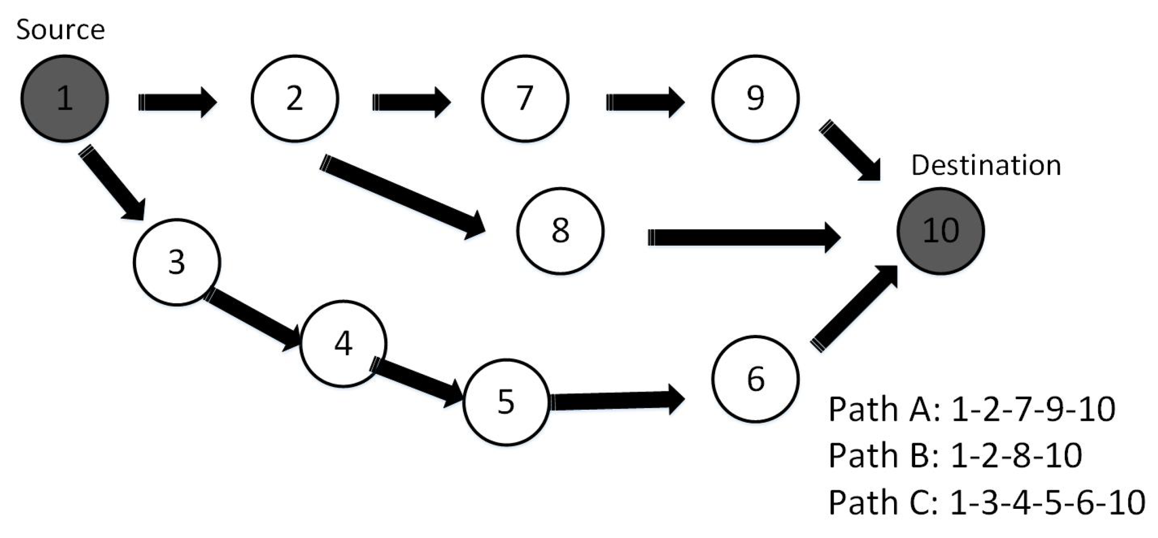
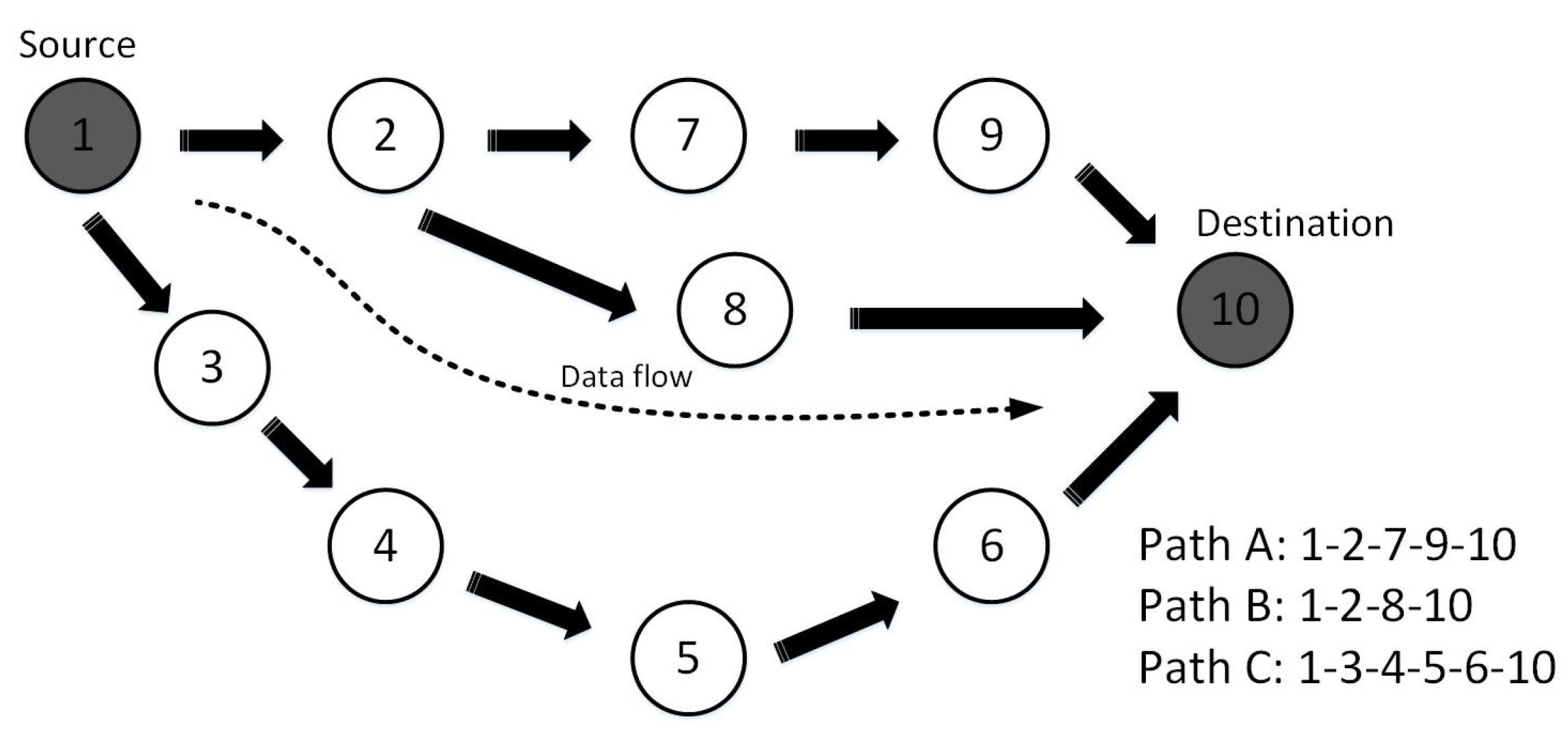
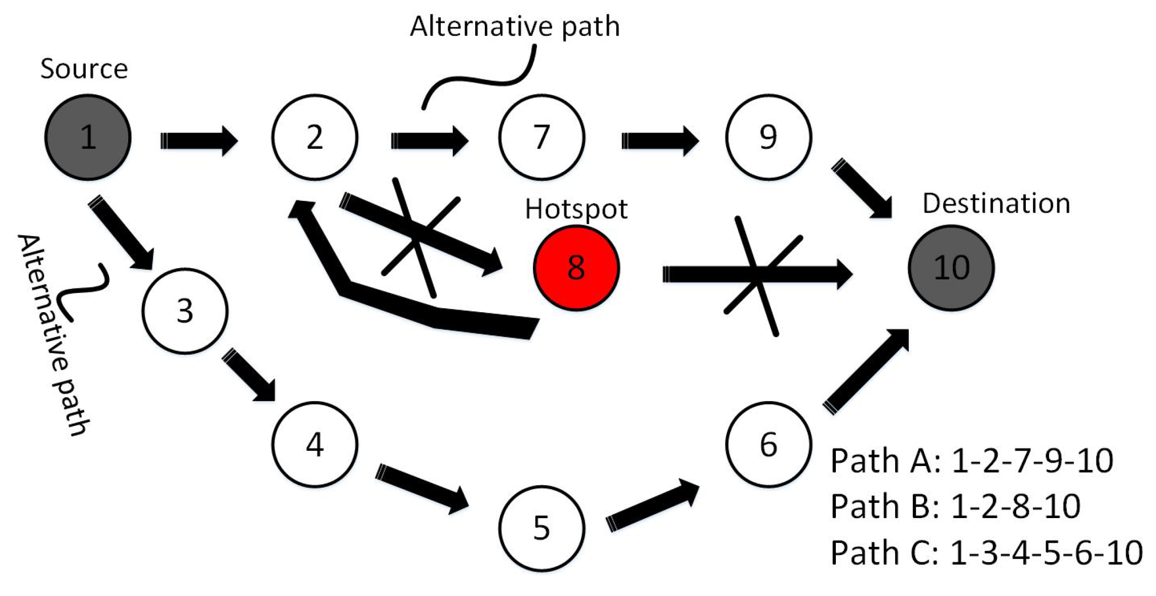
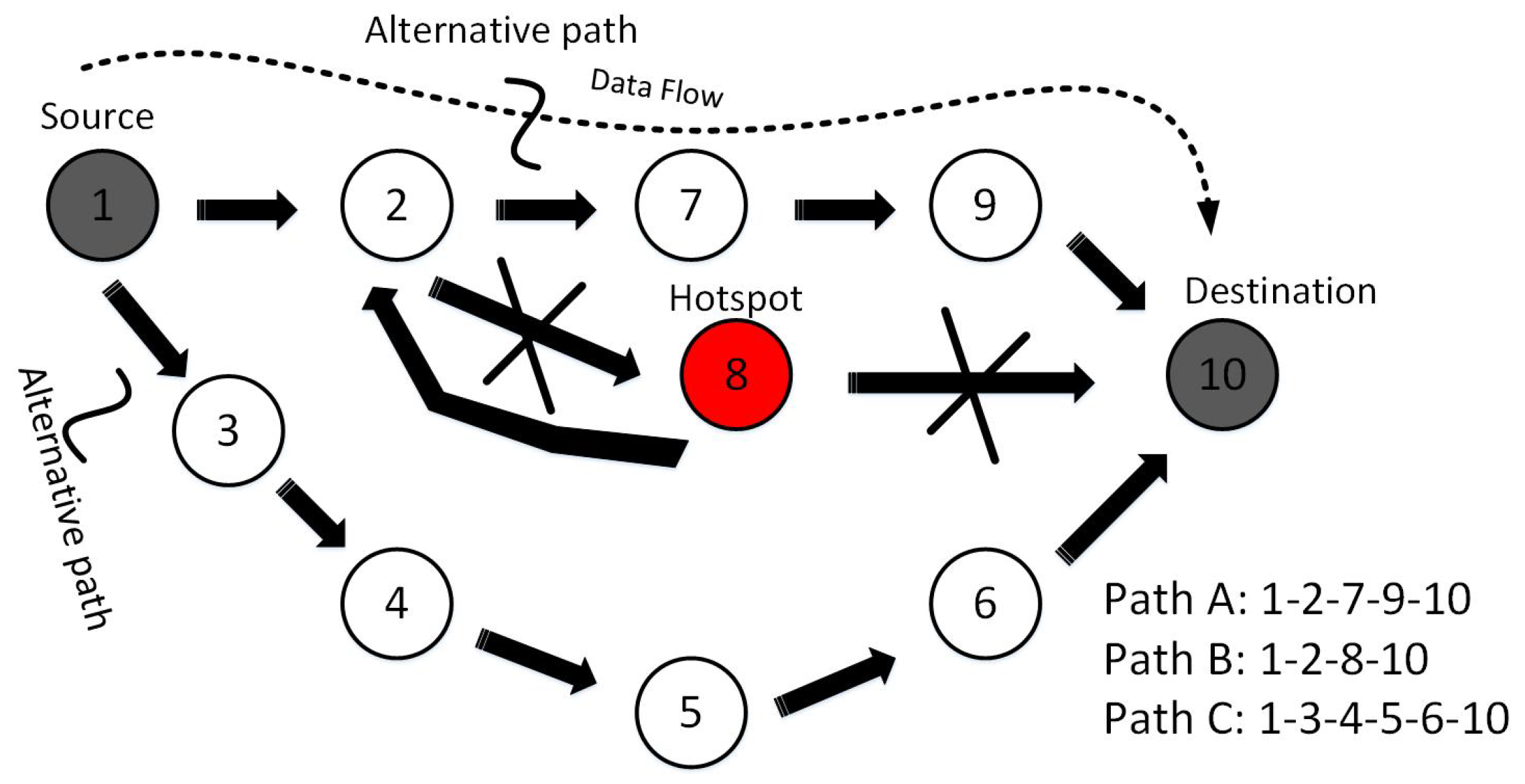
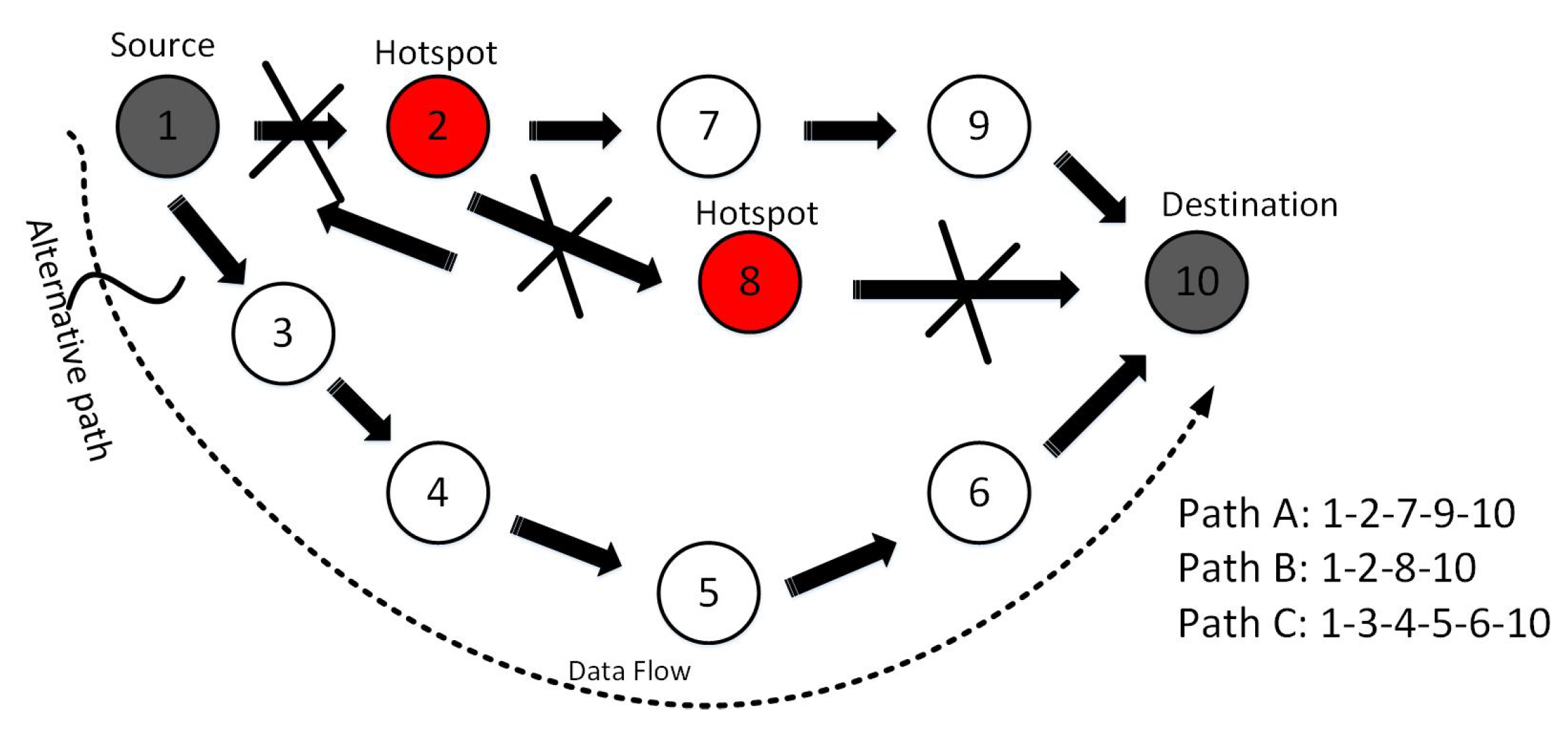
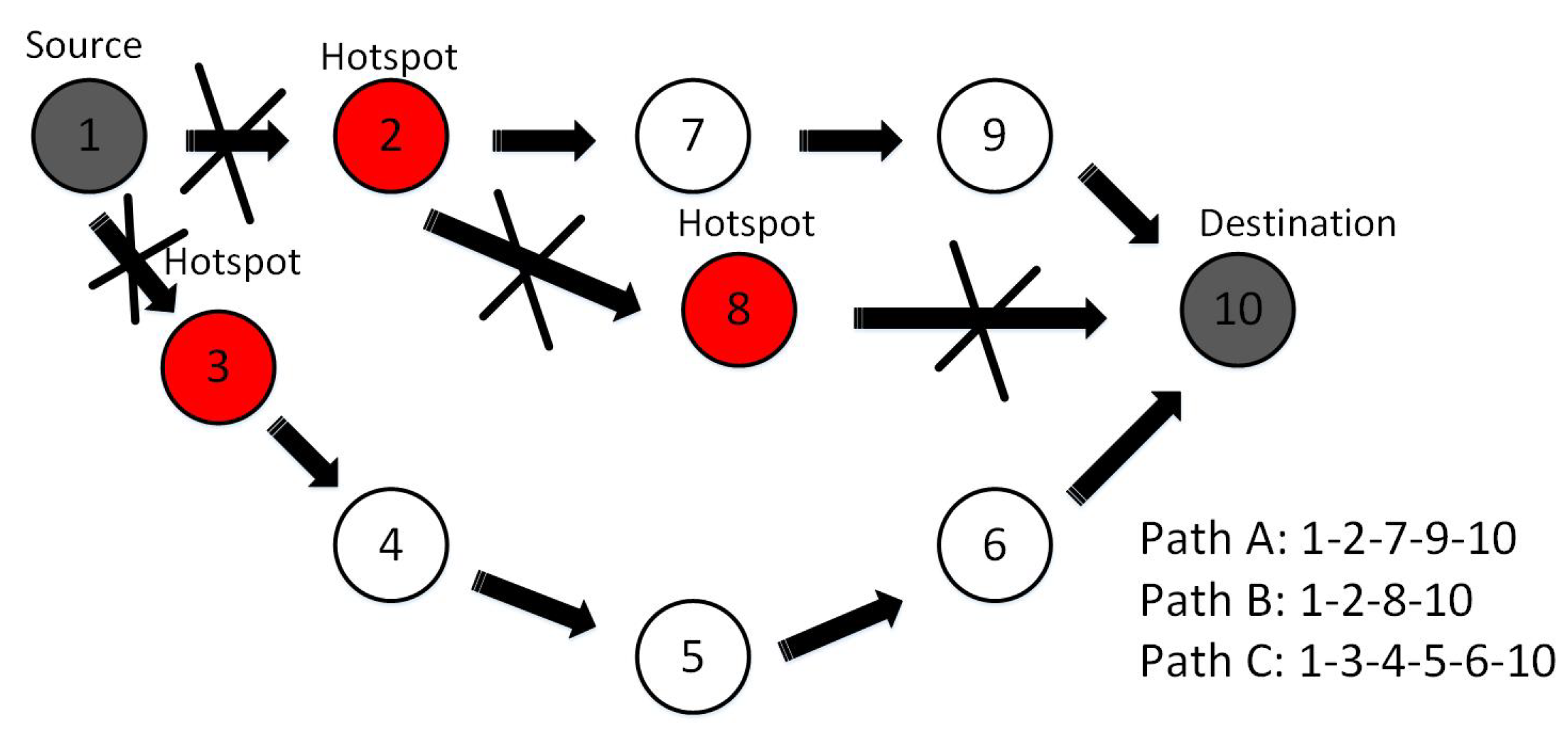
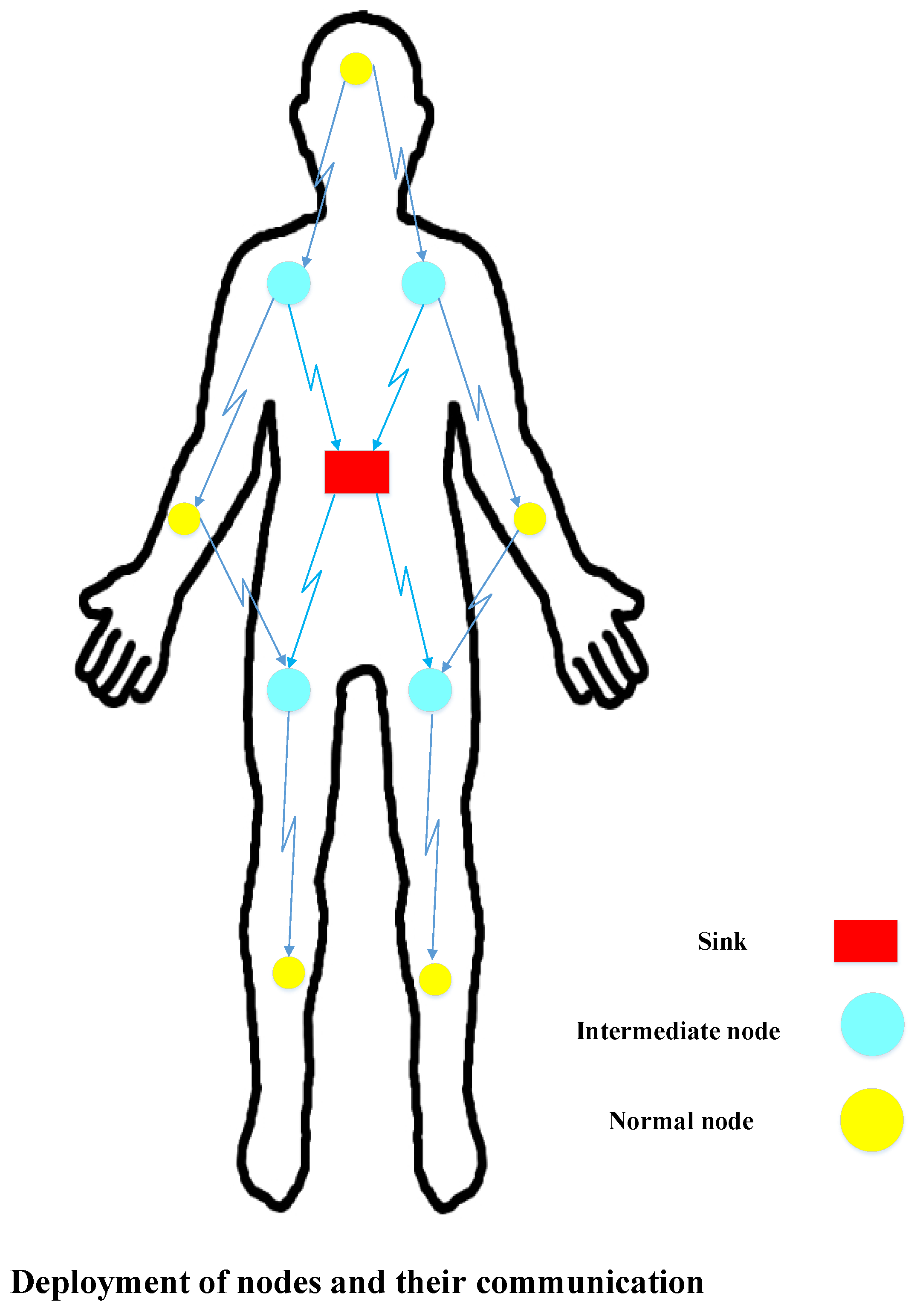
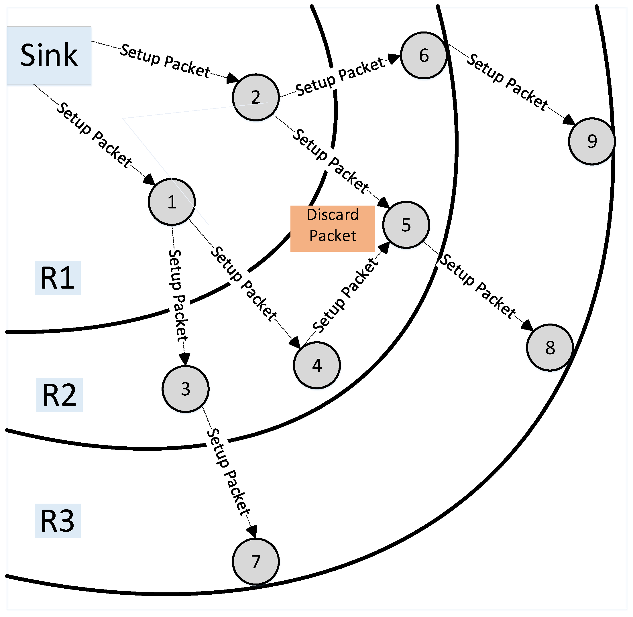
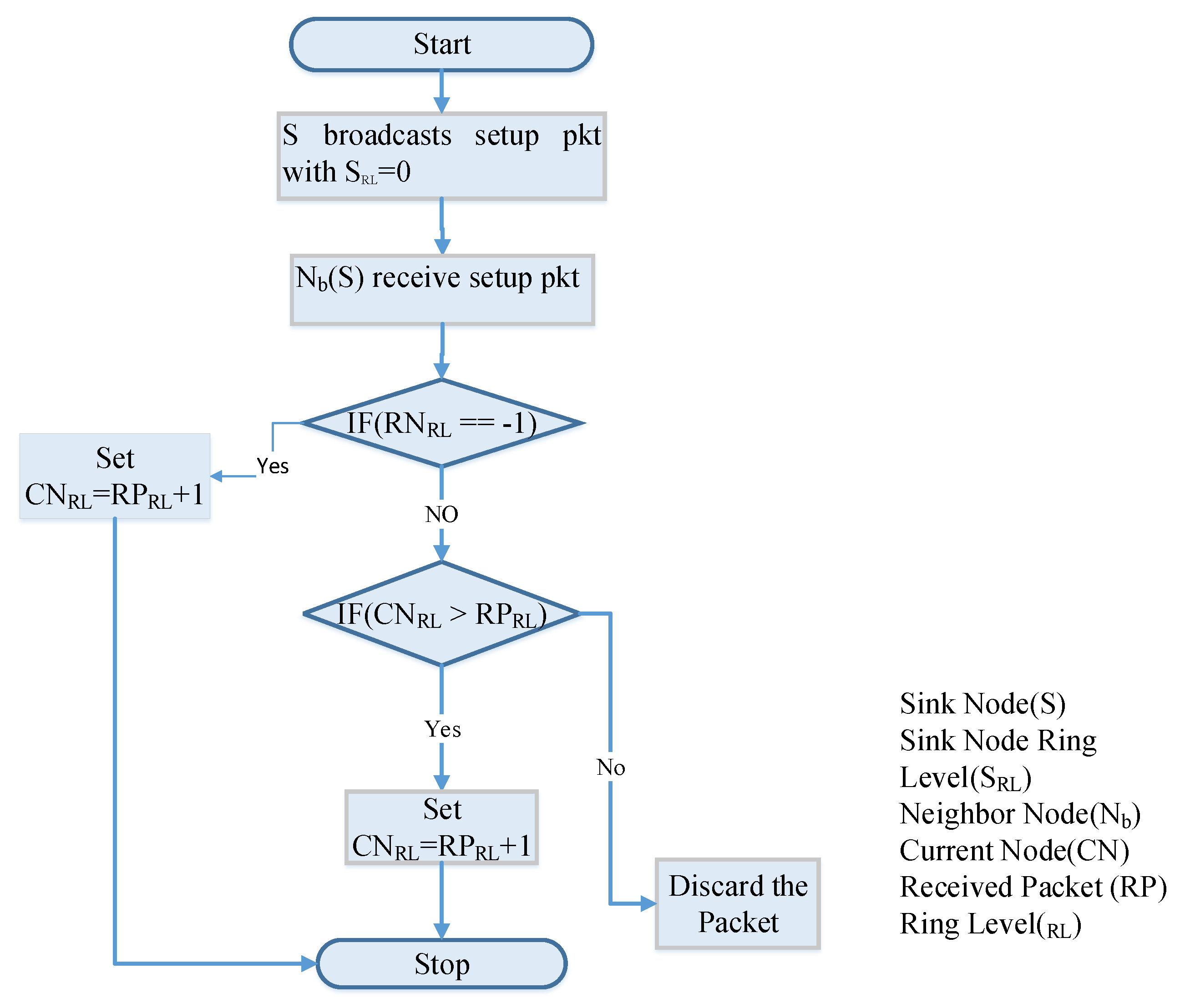
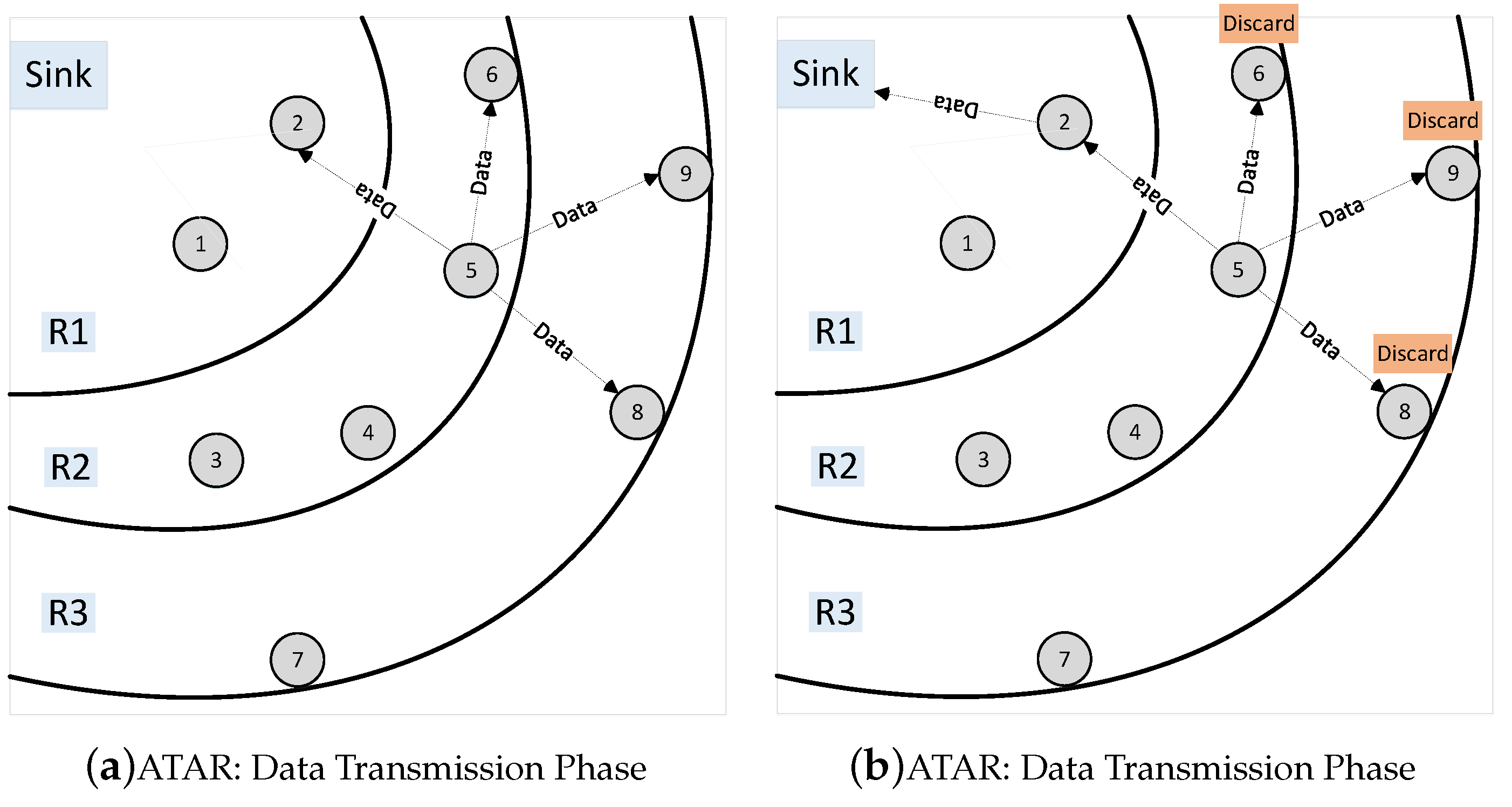
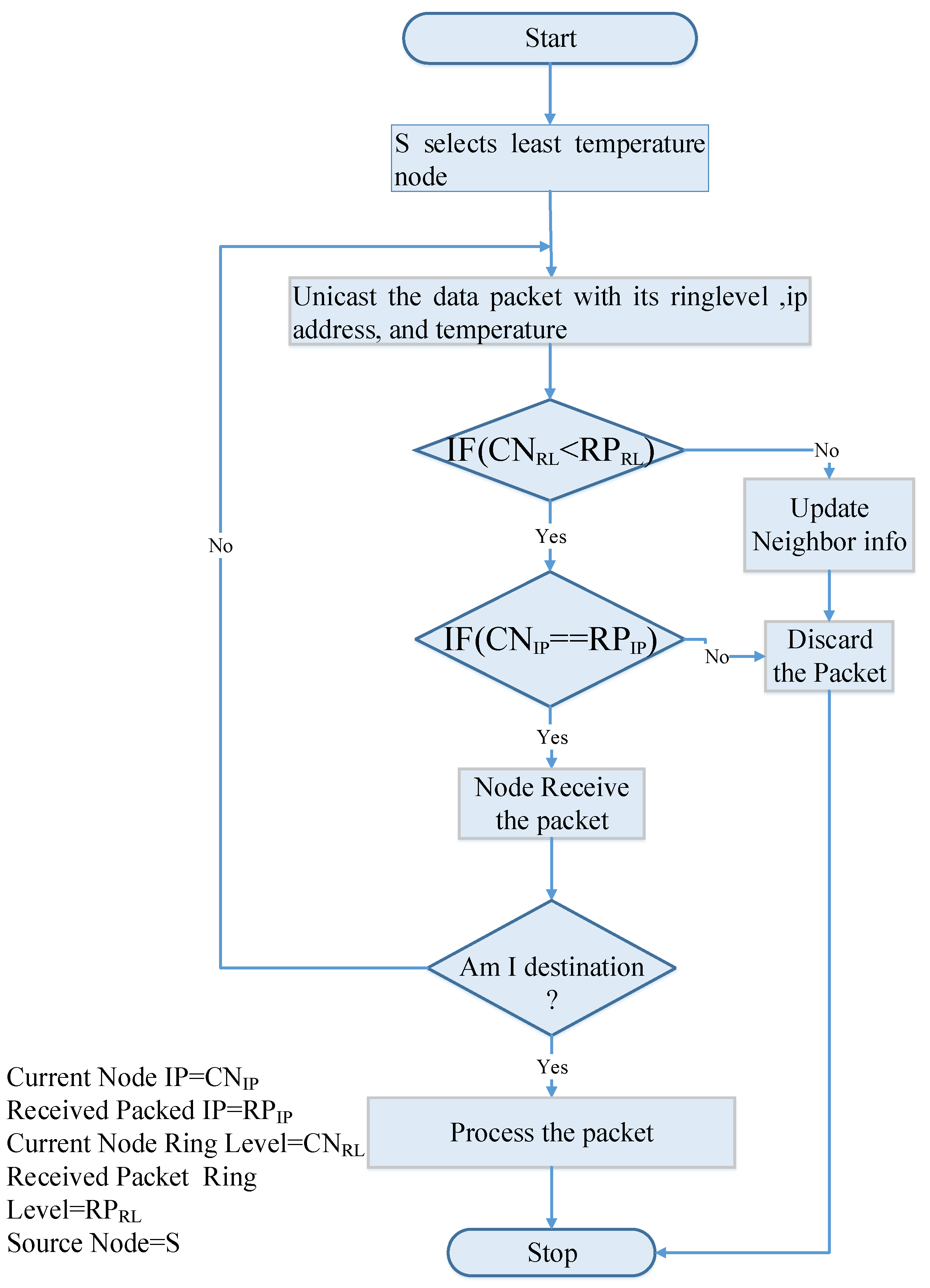
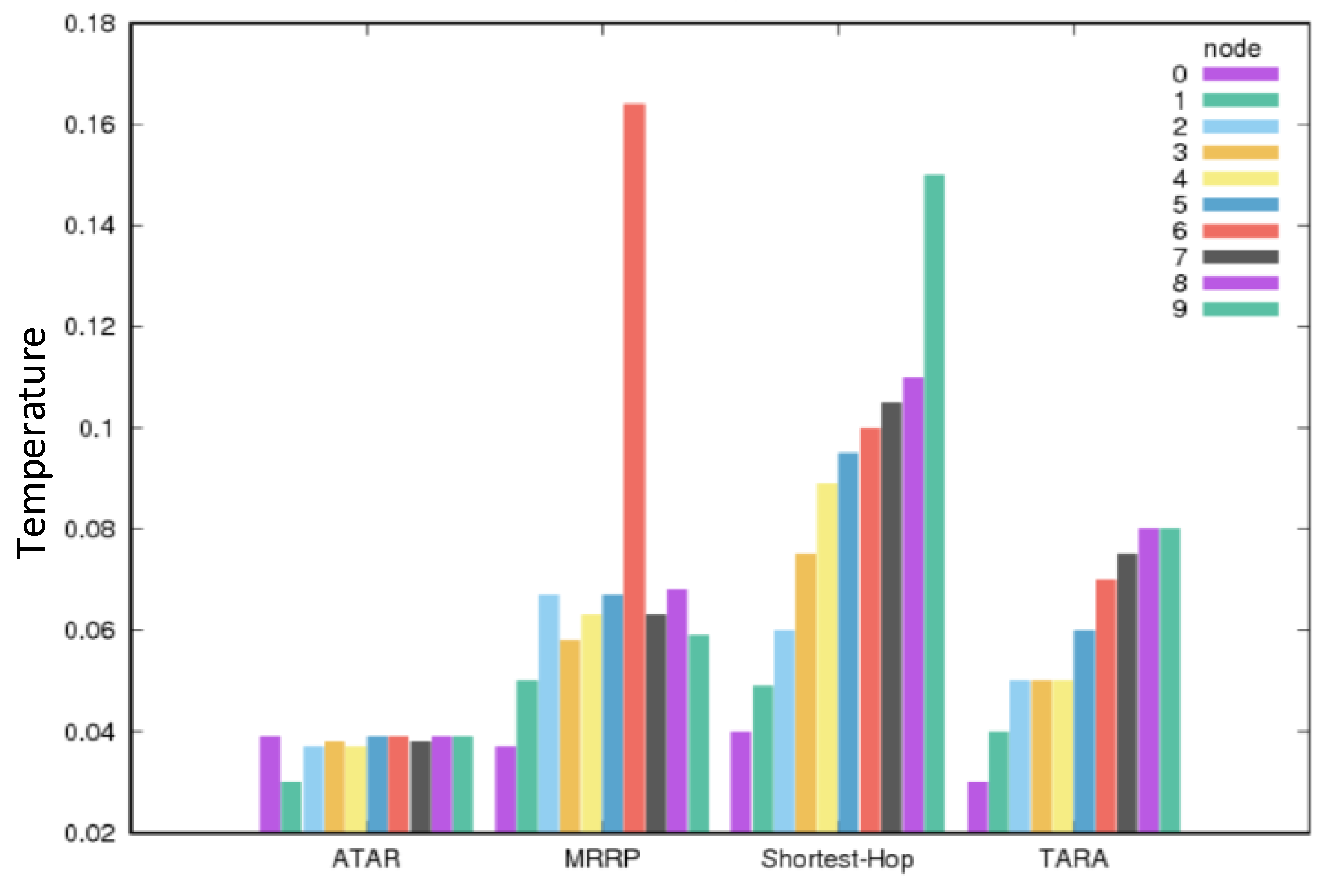
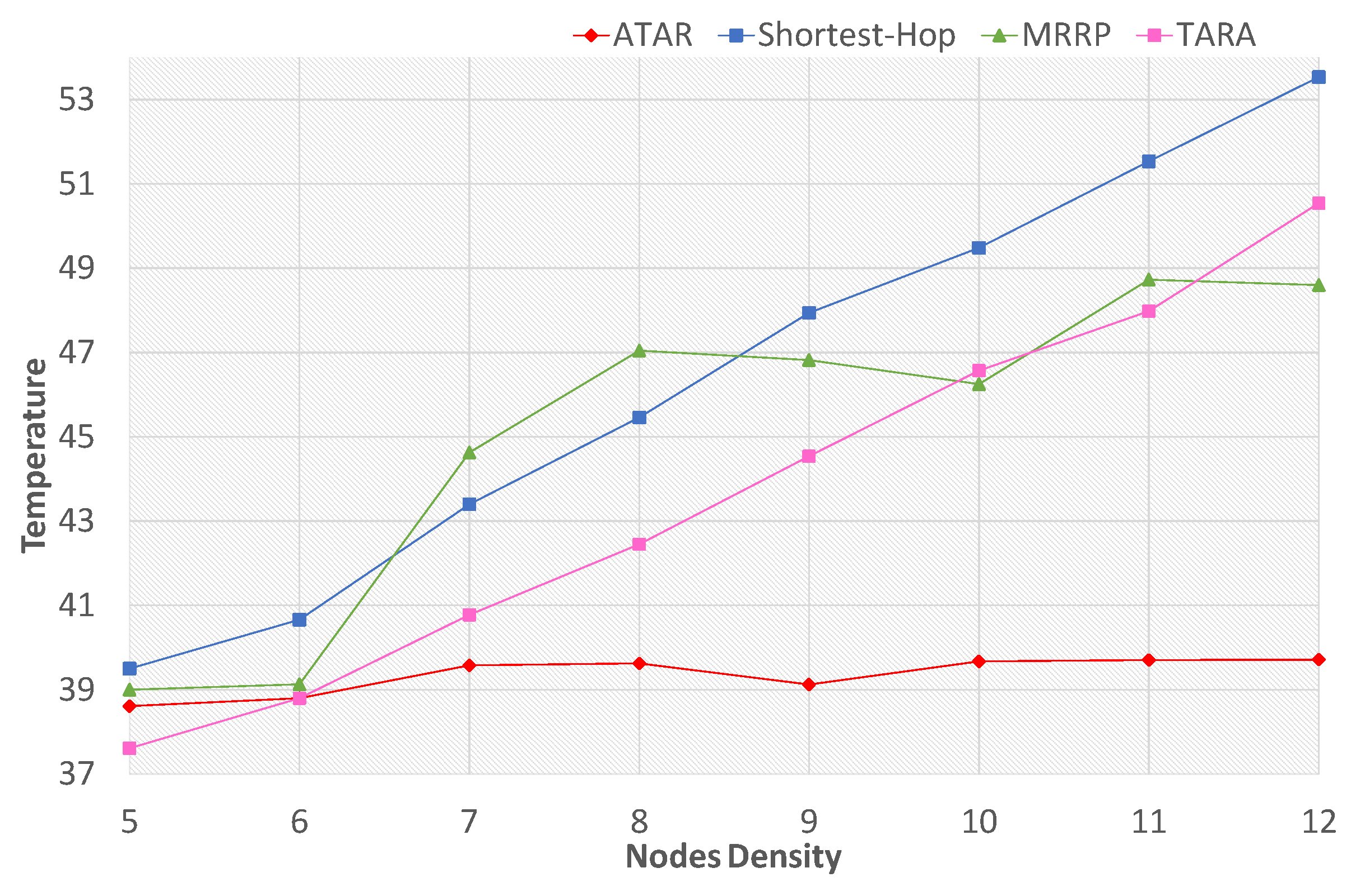
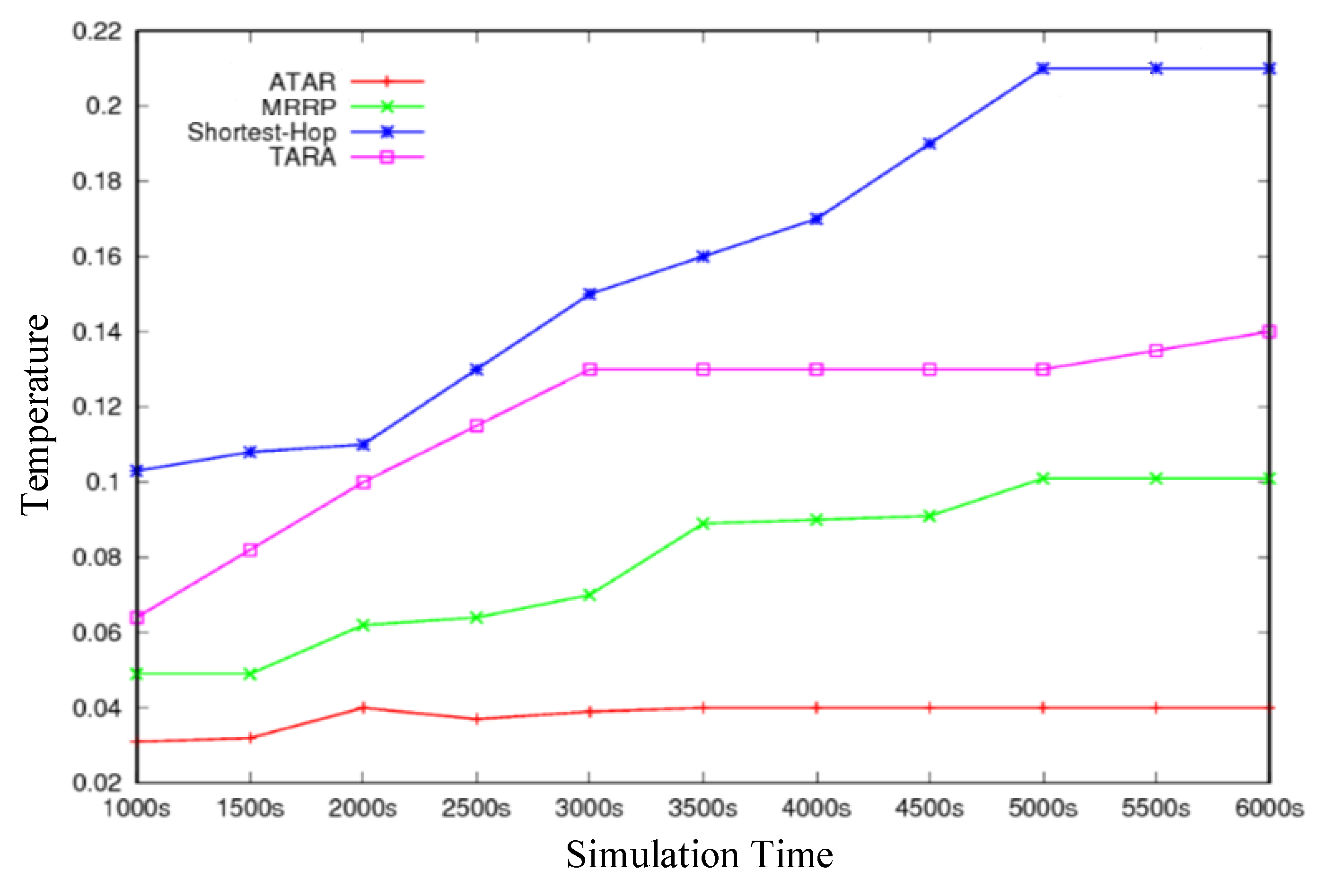
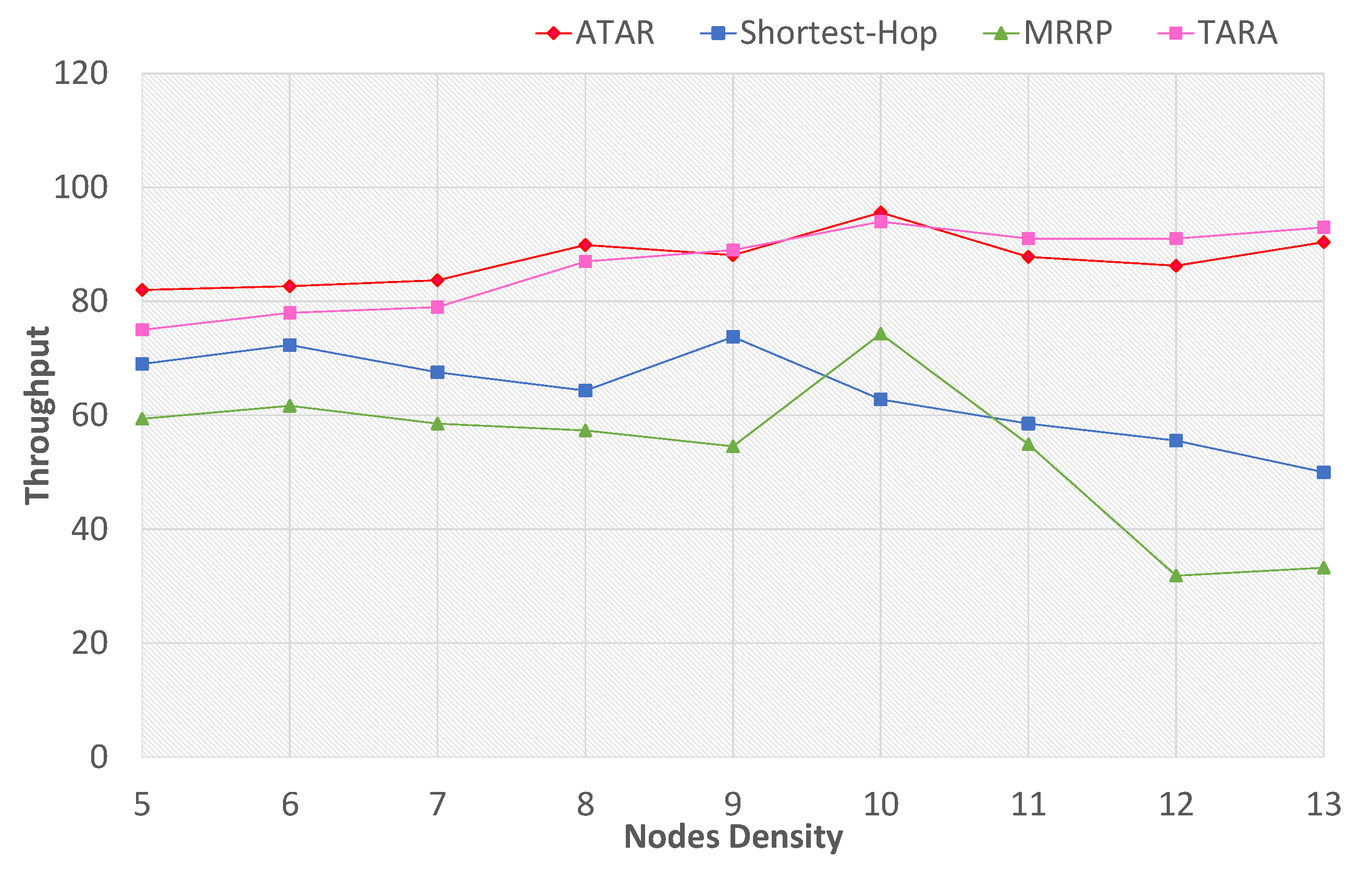
Table 1.
Critical analysis of thermal-aware routing protocols.
| Authors | Approach | Objective | Limitations |
|---|---|---|---|
| Tang et al., 2005 | TARA [25] | To calculate the temperature of neighboring node and redirect the packet from hotspot area. | Packet delay is high. It does not provide hotspot avoidance. Network lifetime is very less. Temperature of nodes in the network is very high. |
| (Bag & Bassiouni, 2006) | LTR [25] | To minimize the overall network temperature and redirect the packet from hotspot area. | Packet drop ratio is high. Network lifetime is less. Temperature of nodes in network is high. |
| (Bag and Bassiouni, 2006) | ALTR [25] | To minimize the overall network temperature. | Average temperature metrics is considered. Network lifetime is less. end-to-end delay is high. |
| Takashi et al., 2007 | LTRT [27] | Minimize the heat produced by implanted bio-medical sensor node. | Average temperature metric is considered. It does not provide hotspot avoidance. Network lifetime is very less. |
| (Bag and Bassiouni, 2007) | HPR [28] | To overcome the problem of hotspot | Network lifetime is less. |
| Bag and Bassiouni, 2008 | RAIN [29] | To be utilized as a part of an in vivo system of homogeneous and id-less biomedical sensor nodes | Packet delay is high. |
| Tabandeh et al. (2009) | TSHR [30] | To diminish the node temperature and to prevent the development of hotspot. | Network lifetime is less. |
| Javed, Abbas and Fareed (2013) | M-Attempt [31] | To redirect the packet away from hotspot link | No alternative route selection in case of dead nodes. Nonuniform load on the nodes. |
| Mostafa and fuad (2014) | TMQoS [32] | To maintain the node temperature at an acceptable level and guarantee the required QoS demand. | Path loss is high. |
| Ahmad and Javaid (2014) | RE-Attempt [33] | To redirect the packet away from hotspot link and increase the network lifetime. | Network lifetime is less. |
| Omid (2014) | [34] | To redirect the packet away from hotspot link and increase the network lifetime in WBSNs. | Temperature of nodes in network is high. |
| Mostafa and fuad (2015) | TLQoS [35] | To maintain the node temperature at an acceptable level, prevent loop formation during communication and guarantee the required QoS demand. | Network lifetime is less. |
| Mostafa and fuad (2017) | DRC [36] | Avoid congestion during communication and maintain the sensor temperature at an acceptable level. | Network lifetime is less. end-to-end delay is high. Path loss is high. |
| Ali, Pardeep and Adnan (2017) | TTRP [37] | To protect data using some cryptography technique and main the temperature rise of bio-medical sensor nodes. | end-to-end delay is high. |
| Mercy (2017) | TRPL [38] | To redirect the packet from hotspot area and maintain the temperature of the node at an acceptable level. | Packet drop is high. |
Table 2.
Simulation setup.
| Simulation Setup | |
|---|---|
| Simulation Area | 3 m × 2 m |
| Number of implanted nodes | 9 |
| Sink | 1 static |
| Initial temperature of a node | 35 C/0.035 C |
| Size of a Packet | 296 bits |
© 2019 by the authors. Licensee MDPI, Basel, Switzerland. This article is an open access article distributed under the terms and conditions of the Creative Commons Attribution (CC BY) license (http://creativecommons.org/licenses/by/4.0/).
Share and Cite
MDPI and ACS Style
Jamil, F.; Iqbal, M.A.; Amin, R.; Kim, D. Adaptive Thermal-Aware Routing Protocol for Wireless Body Area Network. Electronics 2019, 8, 47. https://doi.org/10.3390/electronics8010047
AMA Style
Jamil F, Iqbal MA, Amin R, Kim D. Adaptive Thermal-Aware Routing Protocol for Wireless Body Area Network. Electronics. 2019; 8(1):47. https://doi.org/10.3390/electronics8010047
Chicago/Turabian StyleJamil, Faisal, Muhammad Azhar Iqbal, Rashid Amin, and DoHyeun Kim. 2019. "Adaptive Thermal-Aware Routing Protocol for Wireless Body Area Network" Electronics 8, no. 1: 47. https://doi.org/10.3390/electronics8010047
Note that from the first issue of 2016, this journal uses article numbers instead of page numbers. See further details here.