Article

Low-Profile and Closely Spaced Four-Element MIMO Antenna for Wireless Body Area Networks

1
Mobile Systems Group, Instituto de Telecomunicações, 3810-193 Aveiro, Portugal
2
Centre For Wireless Technology, Faculty of Engineering, Multimedia University, Cyberjaya 63100, Malaysia
3
Department of Electrical Engineering, CECOS University of IT and Emerging Sciences, Peshawar 25000, Pakistan
4
Department of Electronics, University of Ferhat Abbas, Setif -1-, 19000 Setif, Algeria
5
Department of Telecommunication Engineering, UET Mardan 23200, Pakistan
6
Faculty of Computing, Engineering and Science, University of South Wales, Pontypridd CF37 1DL, UK
7
School of Engineering and Informatics, University of Bradford, Bradford BD7 1DP, UK
8
Department of Communication and Informatics Engineering, Basra University College of Science and Technology, Basra 61004, Iraq
*
Authors to whom correspondence should be addressed.
Electronics 2020, 9(2), 258; https://doi.org/10.3390/electronics9020258
Submission received: 10 December 2019 / Revised: 15 January 2020 / Accepted: 27 January 2020 / Published: 4 February 2020
(This article belongs to the Special Issue Recent Technical Developments in Energy-Efficient 5G Mobile Cells)

Abstract

:
A compact four-element multiple-input multiple output (MIMO) antenna is proposed for medical applications operating at a 2.4 GHz ISM band. The proposed MIMO design occupies an overall volume of 26 mm × 26 mm × 0.8 mm. This antenna exhibits a good impedance matching at the operating frequency of the ISM band, whose performance attributes include: isolation around 25 dB, envelope correlation coefficient (ECC) less than 0.02, average channel capacity loss (CCL) less than 0.3 bits/s/Hz and diversity gain (DG) of around 10 dB. The average peak realized gain of the four-element MIMO antenna is 2.4 dBi with more than 77 % radiation efficiency at the frequency of interest (ISM 2.4 GHz). The compact volume and adequate bandwidth, as well as the good achieved gain, make this antenna a strong candidate for bio-medical wearable applications.

1. Introduction

Due to the tremendous demand for high data rate and large channel capacity, developing multiple-input multiple-output (MIMO) antenna systems is given more attention by industry and academia. The key goals of the MIMO system is to accomplish multiband operation, enhanced bandwidth, improved gain/efficiency, good channel capacity and diversity performance [1].
To achieve a high quality data transmission, the multi-input multi-output (MIMO) antenna technology has been promoted and has become an eye-catching choice for antenna designers. However, a good MIMO antenna should meet several important factors, such as ensuring high isolation between elements, while obtaining a good impedance characteristics and highly efficient individual elements [2,3]. Therefore, the MIMO technology has been extensively considered and exploited to improve the channel capacity and signal quality.
In this context, the isolation between the closely spaced elements largely affects the antenna system performance [4,5]. Subsequently, one of the most challenging tasks in the MIMO paradigm is to accomplish high isolation and low correlation between different elements, in which this will contribute to increasing the channel capacity and consequently obtain both a higher gain as well as good spectral efficiency.
The conventional methods for mitigating the mutual coupling is to position antenna elements with adequate spacing (typically half wavelength distance). Although this approach can solve the coupling issue, it needs such a huge space of deployment, which is not a convenient approach to be used within hand held wireless devices due to the limited space. Thus, for the goal of having higher functionality and reliability, numerous approaches have been lately used to reduce inter-element coupling and hence improve isolation. The achievable data rate throughput in wireless communication would be multiplied and increased within the multiple-input multiple-output (MIMO) system [6,7]. The MIMO approach helps in optimizing the use of the transmission spectrum and power [8,9]; by exploiting MIMO synthesis, additional paths may be utilized in order to improve the link capacity [10,11].
The industrial, scientific and medical (ISM) band of 2.4 GHz is broadly considered as an exempted license band, with minimal free access regulation. This band has been largely exploited in several applications such as cordless phones, medical applications and Wi-Fi standards of 802.11 a,b,g,n. The 802.11n standard was defined in October 2009 and has since then become broadly used in many applications. This standard utilizes ISM frequency bands of 2.4 GHz or 5.8 GHz and is interoperable with 802.11b, and uses 802.11g-like modulation, but with MIMO. There have been various investigations on antenna design at the 2.4 GHz ISM band frequency as in [12,13,14,15,16,17,18].
However, such antennas are not wearable antennas for use in real applications. Thus, several investigations on the wearable antenna designs have been carried out. These include different kinds of antenna shapes and structures [19,20,21,22,23,24,25,26,27,28,29,30], such as conformal dipole and monopole antennas [19,20], wideband implantable antennas [21,22], circularly polarized antennas [23,24], and capsule antennas [25,26]. The main goal of such investigations was to meet wearable antenna requirements in accomplishing robust communication ability for wearable devices to detect major vital signs and bio-electric activity.
On the other hand, most wearable antennas in [19,20,21,22,23,24,25,26,27,28,29,30] are single-input–single-output (SISO) designs. Once their structure and characteristics are accomplished, size dimensions as well as bandwidth are static. For further improvements, such as enhancing the transmission rate data and avoiding the multipath interferences phenomena, an introduction of an additional antenna characteristic should be taken into account. Special consideration and attentions have been given to multiple-input multiple-output (MIMO) technology, with the potentiality of improving channel capacity, but without need for additional frequency spectrum or power.
In MIMO wireless systems, multiple antenna elements are adopted to work as transmitter and receiver, improving the data transmission rates of high-resolution images from the capsule to outside base station/gateway over single antenna topology in multipath channels [31]. Recently, planar monopole antennas with a pair of elements were proposed, verifying that antennas operate at ISM 2.4 GHz along with MIMO technique that can be applied for wireless devices, realizing high data rate in limited range and space [32,33,34,35,36,37,38].
However, none of the above-mentioned antenna structures have been placed on the human body to check the impact on performance, limiting studies targeting medical applications. Thus, this work proposes a four-element monopole compact antenna operating over the ISM 2.4 GHz band, which is then placed on the human body for medical investigations. To claim the novelty or/and advantages of the present work, a comparison table of previous similar published antennas has been included. By reviewing all ISM 2.4 GHz band MIMO antennas in Table 1, one can observe that the proposed antenna has achieved a smaller size compared to all works in [32,33,34,35,36,37,38], higher isolation in contrast to antennas in [32,33,37], improved ECC with comparison to refs [30,35], and better power gains over the designs in [33,36,38]. Moreover, the proposed antenna has been embedded on the body and its performance compared with free space antennas.

2. Antenna Design And Concept

The proposed design consists of four p-shaped monopole radiators as shown in Figure 1. The proposed ISM 2.4 GHz MIMO antenna is printed on FR-4 dielectric substrate (permittivity of 4.3, loss tangent of 0.025, and thickness of 0.8 mm). The proposed geometry of the four-element MIMO monopole antenna is considered as one of the smallest designs in wearable antennas with a total size of 26 × 26 × 0.8 mm 3 . As can be seen in Figure 1, the proposed antenna is fed by a single 50 Ω microstrip line designed and printed on FR-4 substrate. Initially, a single-element antennas was investigated. The dimensions of the antenna were optimized at the desired frequency (2.4 GHz). The fabricated prototype of the single-element antenna is portrayed in Figure 2a. The simulated and measured reflection coefficients of the antenna are shown in Figure 2b. We see that the simulated and measured results have the same resonant frequency. The bandwidth of the fabricated prototype is smaller than the simulated one but still wider than the targeted ISM band.
The four p-shaped elements are symmetrically placed with a separation distance of 4.5 mm (0.06 λ ). The very small ground plane is printed on the lower side of the substrate, where this appellation is used in [39,40,41]. The ground plane was defected into four rectangle parts printed underneath each radiating element. The schematic views of the considered radiating element (front side) and partial ground (back side) are shown in Figure 1, along with the optimized dimensions. The present design is simulated with the aid of CST [42]. The detailed geometrical parameters and their sizes are listed in Table 2.

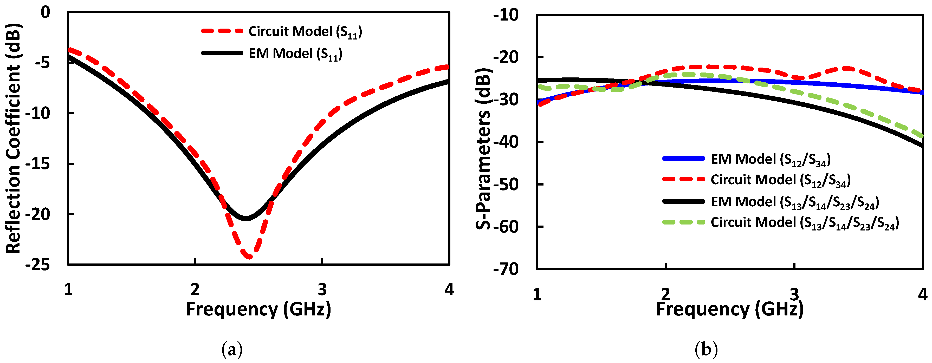
3. Equivalent Circuit Model

In order to evaluate the true behavior of the proposed four elements MIMO antenna, an equivalent lumped circuit model is generated using advance design system (ADS). The equivalent circuit model is illustrated in Figure 3. Each monopole radiator of the MIMO antenna system is represented by the parallel RLC resonant circuit [43,44]. Each monopole is excited by a 50 Ω terminal. The associated coupling between the MIMO elements is represented by an LC circuit [45,46]. The equivalent circuit is fine tuned to extract the optimized circuit values. The optimized circuit parameters are listed in Figure 3. The s-parameters of the circuit and EM model are compared in Figure 4. We can see that the plotted curves present satisfactory agreement.

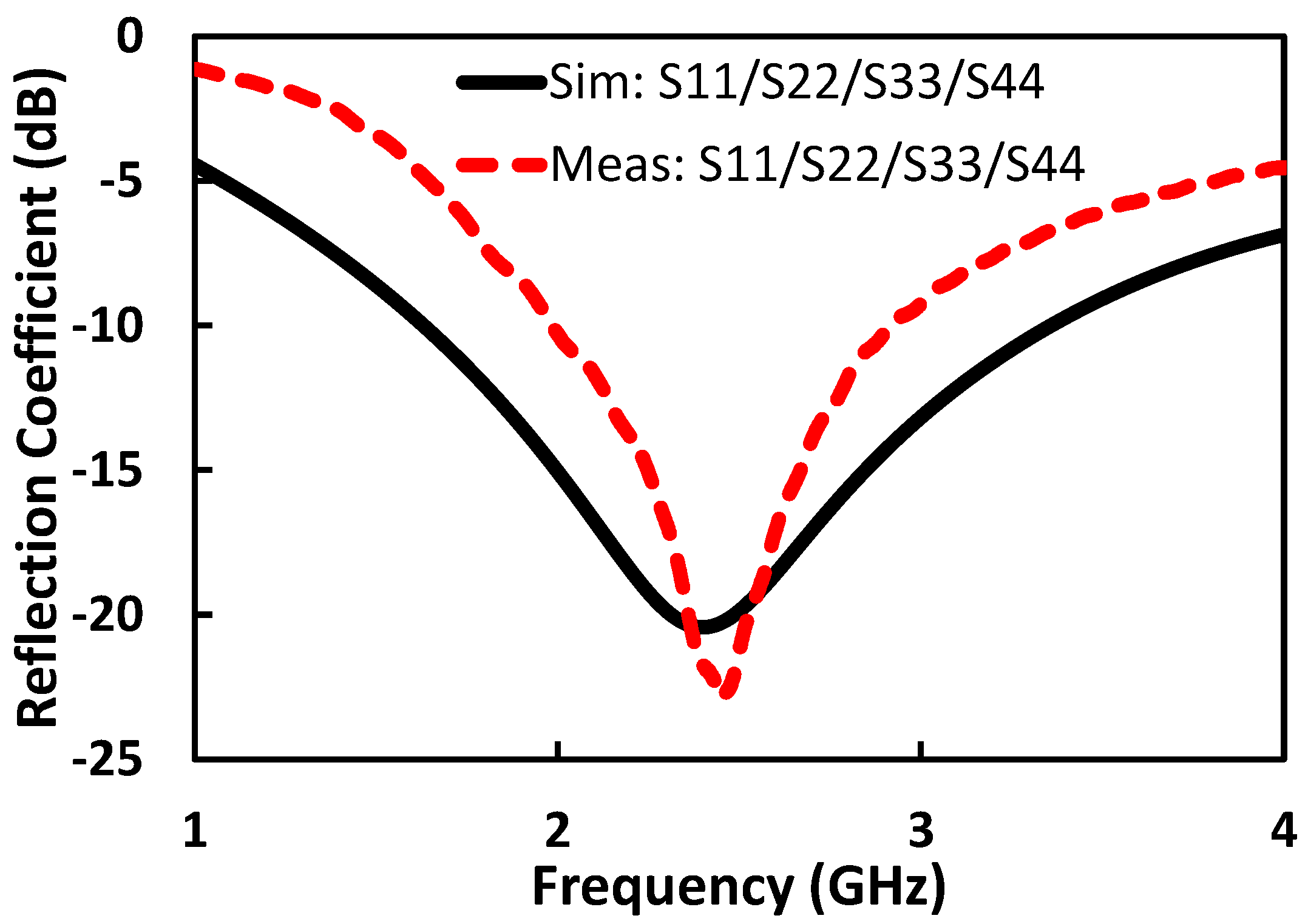
4. Simulation and Measurement Results

The computed and measured s-parameters of the antenna are demonstrated in Figure 5. It is observed that the proposed MIMO antenna has simulated −10 dB impedance bandwidth at the 2.4 GHz ISM band, where it shows isolations between the adjacent and diagonal ports of around −25 dB.
For proof-of-concept, the four-element MIMO antenna model is fabricated as depicted in Figure 6. The MIMO antenna was printed over FR-4 substrate with thickness of 0.8 mm. Four rectangle copper parts were printed underneath each radiating element to mimic the partial ground plane of the antenna. Four SMA connectors were exploited to feed the four-element radiators as illustrated in Figure 6. The measured s-parameters of the proposed MIMO antenna in Figure 5 show a good agreement with the simulated outcomes, with an insignificant move in the resonant frequency, which can be attributed to several factors such as the fabrication process and error and port/cable coupling losses.
To further investigate the MIMO antenna diversity performance, the isolation between the elements of the proposed antenna were studied and analysed as it is directly related to the minimum coupling between individual antenna elements. The simulated and measured isolation outcomes between the MIMO antenna elements are indicated in Figure 7. The isolation values vary from 18 to 23 dB in the impedance band of the proposed antenna. The results show good performance for MIMO applications around 2.4 GHz with isolation greater than −25 dB.

5. Current Distribution

To validate the outcome of the mutual coupling between the antenna elements of the proposed antenna obtained in Figure 4, Figure 5 and Figure 7, we can refer to the antenna surface current as indicated in Figure 8. Generally, to understand the influence of the coupling between the antenna elements using this approach, one of the four ports should be excited, whereas the other three ports remain terminated with 50 Ω load as shown in Figure 8. The space between the ports is considered as an important factor in order to figure out how much the antennas are being isolated. Generally speaking, when the antenna elements are largely separated, this will lead to a high isolation.
In the case of Figure 8a, only port 1 is excited. As observable from Figure 8a, the higher value of current concentrates on the feed arm, as there is no current linked to the adjacent ports. Therefore, its effect can be seen in terms of the S12 (or S34) isolation parameter. When port 2 is excited and the other three ports are terminated with 50 Ω load, the current only exist on this port while being negligible on the remaining three. The same case is illustrated when port 3 and port 4 are only excited as indicated in Figure 8c,d. From Figure 8, it can be observed that the surface current is mainly focused over the excited port. Therefore, the measured and simulated isolations for the proposed MIMO antenna that were shown in Figure 5 and Figure 7 are more than 10 dB.
Two planes, i.e., E-plane and H-plane at 2.4 GHz are taken in order to examine the radiation patterns of the proposed antenna as illustrated in Figure 9, when one port is excited and the others are matched to a 50 Ω load. As it is noted, the E and H plane simulated field patterns of the present MIMO antenna are shown at the ISM 2.4 GHz resonant frequencies, which are generated by the CST software package. The measured radiation is taken and carried out inside an anechoic chamber in the presence of a standard horn antenna (as transmitter) and the power meter (to record the received field). In the measurement process, any one port is chosen to work as a receiver, while the other ports are loaded with 50 Ω load, for the reason of avoiding any signal pick-up. Such a procedure is repeated with every port of the proposed MIMO design. The measured and CST simulated radiation patterns are compared in Figure 9 in the case of the two planes. Thanks to the symmetric geometry of the proposed antenna that helps in accomplishing a stable radiation pattern, we consider an appropriate design for use in communication systems. However, certain irregularities between the simulated and measured patterns are observed and this may be attributed to the fabrication process errors, and the losses of the ports/cables.

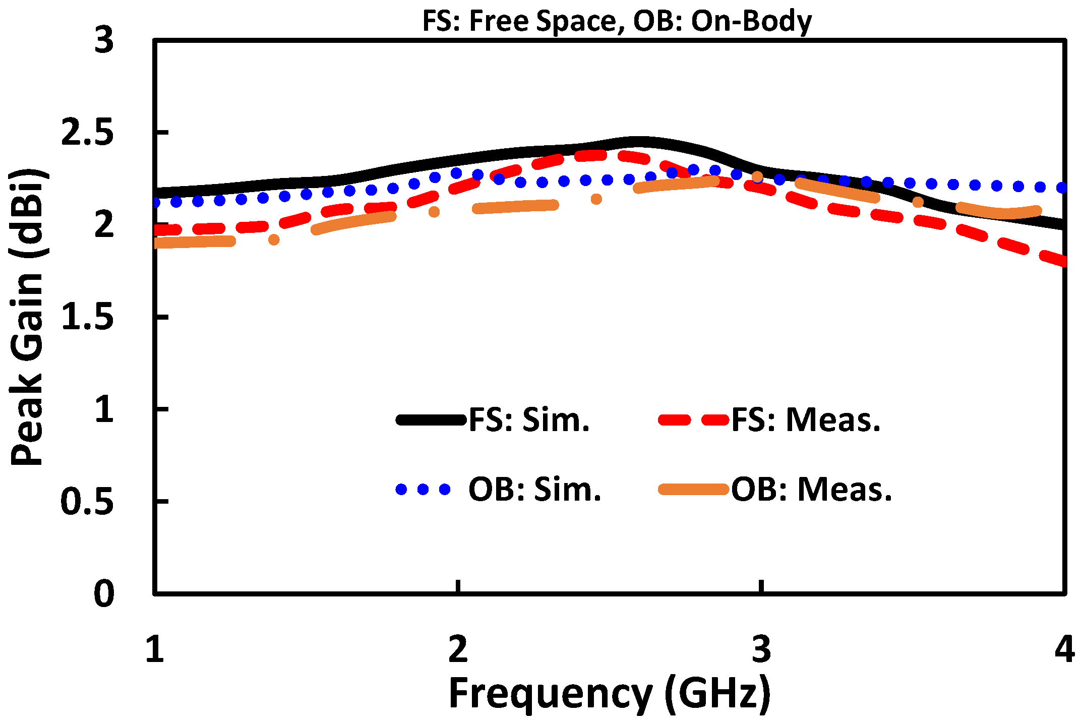
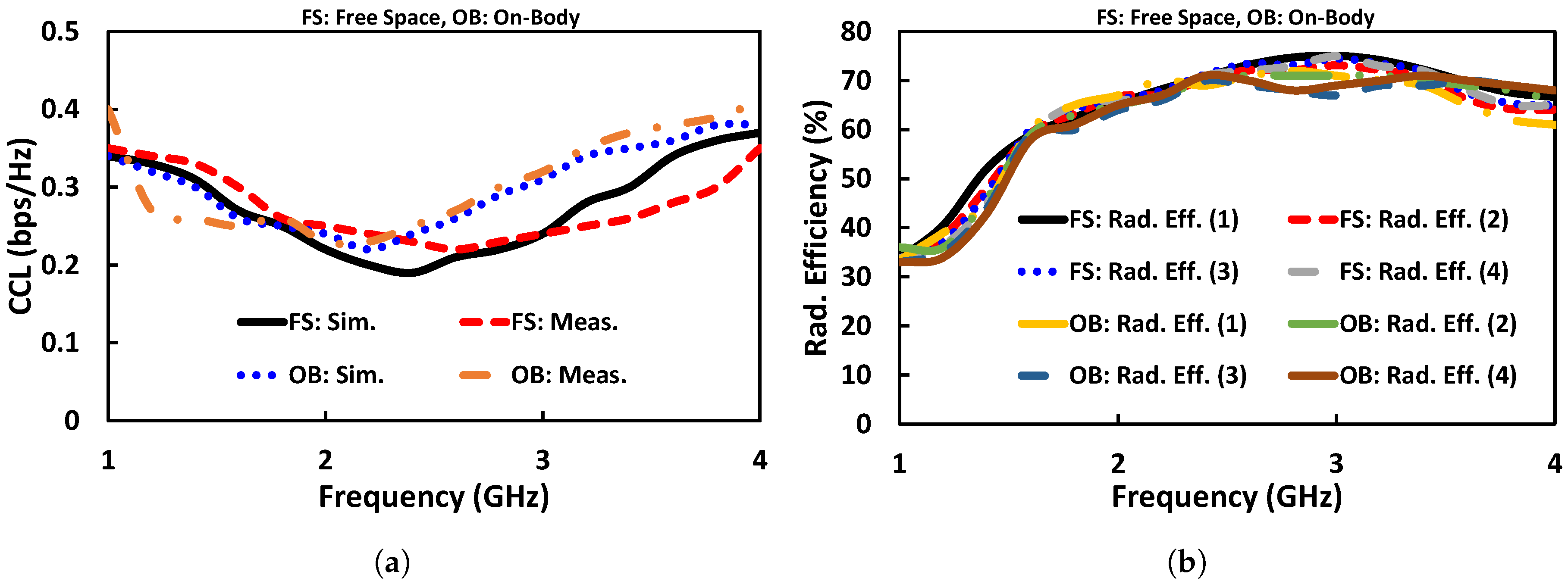
6. Antenna ON-Body Investigation

The human body can absorb electromagnetic (EM) waves (termed as specific absorption rate, SAR), generated by antenna operated in its vicinity. If this absorption of EM waves exceeds some standard limits, the temperature of the tissues will rise [47]. These limits are standardized by the electromagnetic field (EMF) regulation authorities (ICNIRP, IEEE, and FCC). Considering public safety concerns, we have calculated the specific absorption rate (SAR) according to IEEE C95.1-2005 as shown in Figure 10. The antenna was placed on the chest, arm, and leg of a real realistic Ella model while maintaining some gap to avoid direct contact with tissue as shown in Figure 10. Figure 10a–c show the SAR distributions on the chest, arm, and leg of the Ella model. We selected small areas for SAR calculation instead of full body to reduce simulation time. The peak 10-g SAR values 20 W/kg, 8.36 W/kg, and 7.17 W/kg at 1 W input power to each array element on the chest, arm, and leg, respectively. The peak SAR values exceed the standard limits; however, the devices operating near the body use little power. The standard maximum allowable power (EIR) for such devices is set in the mW range [48,49,50]. To restrict the SAR value under the limit for our proposed antenna, the maximum input powers to the antenna are 100 mW, 239.2 mW, and 278.9 mW for the chest, arm, and leg, respectively, which are much greater than the standard radiated limit (in mW range). Based on the above SAR calculated value, our antenna is safe if the input power is less than than 100 mW, 239.2 mW, and 278.9 mW for the chest, arm, and leg cases, respectively.
Additionally, the antenna’s performance in terms of reflection coefficient, gain, and radiation pattern is evaluated in the vicinity of the human body. The reflection coefficient of the antenna in free space and in on-body worn scenarios is illustrated in Figure 11a. We can see that the resonant frequency shifts a bit towards the lower frequency side due to body loading effects [51]; however, the antenna still retains a good impedance bandwidth and covers the targeted ISM band (2.4 GHz). Figure 11b,c illustrate the radiation pattern of the antenna in free space and in the vicinity of the human body. We can see that the front-to-back ratio of the antenna in Phi = 0 0 is enhanced due to the fact that skin behaves as an extension of the ground plane [52].
The antenna gain is also one of the diversity parameters. The MIMO antenna gain is a far-field parameter and is measured in an Anechoic chamber using the two standard horn antennas and proposed structure. The simulated and measured gains on the free space and on-body paradigms were carried out as depicted in Figure 12. In the case of our design, the minimum value of the computed and measured peak gain is varied between 2.20 dBi and 2.5 dBi. The simulated antenna gain for the free space and on-body analysis at 2.4 GHz resonant frequency is around 2.49 dBi, while the measured gain in the case of free space and on-body worn at the same band is about 2.20 dBi.
Figure 13a illustrates the outcomes of the computed envelope correlation coefficient (ECC) between the ports of the MIMO antenna system in both scenarios, namely, the free space and on-body worn. ECC of the MIMO system portrays how independent the individual elements of the MIMO system are in terms of radiation pattern. It is always desirable in a MIMO system that each element is independent of the other; however, zero value of ECC is difficult in practical applications. In this case, the three ECC values may be accomplished by substituting the appropriate terms ( S 11 = S 22 = S 33 = S 44 , and S 12 = S 21 = S 34 = S 43 , and S 13 = S 31 = S 24 = S 24 , and S 14 = S 41 = S 23 = S 32 ) into the following equations, and can be written as shown in Equations (1)–(3):
ρ e 12 = | S 11 * S 12 + S 12 * S 22 + S 13 * S 32 + S 14 * S 42 | 2 ( 1 - ( | S 11 | 2 + | S 12 | 2 ) + ( | S 13 | 2 + | S 14 | 2 ) ) 2
ρ e 13 = | S 11 * S 13 + S 12 * S 23 + S 13 * S 33 + S 14 * S 43 | 2 ( 1 - ( | S 11 | 2 + | S 12 | 2 ) + ( | S 13 | 2 + | S 14 | 2 ) ) 2
ρ e 13 = | S 11 * S 14 + S 12 * S 24 + S 13 * S 34 + S 14 * S 44 | 2 ( 1 - ( | S 11 | 2 + | S 12 | 2 ) + ( | S 13 | 2 + | S 14 | 2 ) ) 2
From Figure 13a, the ECC between the ports is lower than 0.03 for the band of interest. Thus, this value of ECC is reasonable and comparable to the ones achieved in [53], which show a good indication for promising diversity performance.
The diversity gain also is deemed as a paramount diversity parameter [54,55], which may be accomplished in terms of maximum theoretical diversity gain (10 dB) and correlation coefficient exploiting Equation (4)–(6). Diversity gain refers to improvements in signal-to-interference ratio by applying any diversity scheme. As the antenna shows diversity gain with higher values, this means a better isolation is achieved and vice versa. The plots of the diversity gain of the present MIMO antenna in the case of free space and on-body investigations are shown in Figure 13b. From Figure 13b, it is noticed that the values of DG are about 10 dB at the operating band for both paradigms.
D G 12 = 10 1 - | ρ e 12 | 2
D G 13 = 10 1 - | ρ e 13 | 2
D G 14 = 10 1 - | ρ e 14 | 2
The capacity capacity loss (CCL) provides information regarding the maximum limit of the message rate up to which the message can be continuously transmitted without any loss over a communication channel. In theory, the channel capacity can be enhanced by increasing the number of antennas of the MIMO system. Nevertheless, the presence of Rayleigh-fading MIMO channels will induce loss of channel capacity. This loss can be calculated from the correlation matrices given in [55,56]. In the case of a 2 × 2 MIMO system, assuming that only the receiving antenna patterns are correlated and assuming the worst scenario where high signal-to-noise ratio is occurring, the channel capacity loss (CCL) can be evaluated by using the following equation [54,55,56]:
C C L = - l o g 2 det ( Ψ R )
where Ψ R is the receiving antenna correlation matrix that is given by:
Ψ R = ρ 11 ρ 12 ρ 13 ρ 14 ρ 21 ρ 22 ρ 23 ρ 24 ρ 31 ρ 32 ρ 33 ρ 34 ρ 41 ρ 42 ρ 43 ρ 44
where
ρ i i = 1 - | n = 1 N S i n * S n i | , f o r i , j = 1 , 2 , 3 , o r 4 .
and
ρ i j = - | n = 1 N S i n * S n j | , f o r i , j = 1 , 2 , 3 , o r 4 .
The CCLs of the proposed radiator for both scenarios are shown in Figure 14a. Figure 14a reveals that the proposed MIMO antenna achieves acceptable CCL values, which vary from 0.2 to 0.3 around the targeted band of ISM 2.4 GHz (ideally, CCL should be less than 0.4 bps/Hz within the entire operating band). Thus, our investigation proves that good impedance matching and isolation between the two antenna elements lead to low capacity loss in the case of free space as well as on-body worn devices.
The efficiency also describes the diversity behaviour of the proposed MIMO antenna. The values of the radiation efficiencies for the 2.4 GHz ISM band in both cases are around 77%, as shown in Figure 14b.

7. Conclusions

A compact four-element MIMO antenna is designed and presented for the ISM band. The P-shaped radiating elements are realized on a low-cost FR-4 substrate. The proposed antenna occupies a compact envelope dimension of 0.20 λ × 0.20 λ × 0.006 λ , where λ is the wavelength of the operating frequency. The MIMO antenna design has been simulated and also fabricated. Both the simulations and measurements showed high isolation of around −25 dB at the targeted band of 2.4 GHz. In addition, the envelope correlation coefficient, antenna gain, efficiency and channel capacity loss and other performances are also provided. The proposed antenna has also been placed on a human body, where its performance was investigated and showed acceptable results compared to the free space antenna design. Therefore, the proposed MIMO antenna has been shown to be a strong candidate for use in medical applications, as well as for mobile and satellite communications.

Author Contributions

Design and concept, I.E., A.I. and C.Z.; methodology, C.Z. and I.E.; investigation, A.I., W.M., M.S., S.U.; resources, A.I., A.B., and S.U.; writing—original draft preparation, I.E.; writing—review and editing, R.A.-A., I.E., and A.d.O.P.; validation, A.d.O.P., R.A.-A.; supervision, J.R.; project administration, J.R. All authors have read and agreed to the published version of the manuscript.

Funding

This project has received funding from the European Union’s Horizon 2020 research and innovation program under grant agreement H2020-MSCA-ITN-2016 SECRET-722424. This work is also funded by the FCT/MEC through national funds and when applicable co-financed by the ERDF, under the PT2020 Partnership Agreement under the UID/EEA/50008/2019 project.

Acknowledgments

This work is supported by the European Union’s Horizon 2020 Research and Innovation program under grant agreement H2020-MSCA-ITN-2016-SECRET-722424. This work is part of the POSITION-II project funded by the ECSEL joint Undertaking under grant number Ecsel-7831132-Postitio-II-2017-IA,www.position-2.eu.

Conflicts of Interest

The authors declare no conflict of interest.

References

  1. Elfergani, I.; Hussaini, A.S.; Rodriguez, J.; Abd-Alhameed, R. Antenna Fundamentals for Legacy Mobile Applications and Beyond; Springer: New York, NY, USA, 2018. [Google Scholar]
  2. Liao, W.J.; Hsieh, C.Y.; Dai, B.Y.; Hsiao, B.R. Inverted-F/slot integrated dual-band four-antenna system for WLAN access points. IEEE Antenn. Wirel. Pr. 2014, 14, 847–850. [Google Scholar] [CrossRef]
  3. Iqbal, A.; Saraereh, O.A.; Ahmad, A.W.; Bashir, S. Mutual coupling reduction using F-shaped stubs in UWB-MIMO antenna. IEEE Access 2017, 6, 2755–2759. [Google Scholar] [CrossRef]
  4. Fletcher, P.; Dean, M.; Nix, A. Mutual coupling in multi-element array antennas and its influence on MIMO channel capacity. Electron. Lett. 2003, 39, 342–344. [Google Scholar] [CrossRef]
  5. Abdullah, M.; Kiani, S.H.; Iqbal, A. Eight Element Multiple-Input Multiple-Output (MIMO) Antenna for 5G Mobile Applications. IEEE Access 2019, 7, 134488–134495. [Google Scholar] [CrossRef]
  6. Tse, D.; Viswanath, P. Fundamentals of Wireless Communication; Cambridge University Press: Cambridge, UK, 2005. [Google Scholar]
  7. Abdullah, M.; Kiani, S.H.; Abdulrazak, L.F.; Iqbal, A.; Bashir, M.; Khan, S.; Kim, S. High-Performance Multiple-Input Multiple-Output Antenna System For 5G Mobile Terminals. Electronics 2019, 8, 1090. [Google Scholar] [CrossRef] [Green Version]
  8. Winters, J. On the capacity of radio communication systems with diversity in a Rayleigh fading environment. IEEE J. Sel. Area. Comm. 1987, 5, 871–878. [Google Scholar] [CrossRef]
  9. Foschini, G.J.; Gans, M.J. On limits of wireless communications in a fading environment when using multiple antennas. Wireless Pers. Commun. 1998, 6, 311–335. [Google Scholar] [CrossRef]
  10. Garcia-Pardo, C.; Molina-Garcia-Pardo, J.M.; Rodriguez, J.V.; Juan-Llacer, L. MIMO capacity in UWB channels in an office environment for different polarizations. Prog. Electromagn. Res. 2013, 44, 109–122. [Google Scholar] [CrossRef] [Green Version]
  11. Iqbal, A.; Basir, A.; Smida, A.; Mallat, N.K.; Elfergani, I.; Rodriguez, J.; Kim, S. Electromagnetic bandgap backed millimeter-wave MIMO antenna for wearable applications. IEEE Access 2019, 7, 111135–111144. [Google Scholar] [CrossRef]
  12. Murmu, S.K.; Misra, I.S. Design of V-shaped microstrip patch antenna at 2.4 GHz. Microw. Opt. Technol. Lett. 2011, 53, 806–811. [Google Scholar] [CrossRef]
  13. Moosazadeh, M.; Esmati, Z. Small Planar Dual-Band Microstrip-Fed Monopole Antenna for Wireless Local Area Network Applications Using Slotted Conductor-Backed Plane. Microw. Opt. Technol. Lett. 2013, 55, 2380–2383. [Google Scholar] [CrossRef]
  14. Khan, M.U.; Sharawi, M.S.; Steffes, A.; Aloi, D.N. A 4-element MIMO antenna system loaded with CSRRs and patch antenna elements. In Proceedings of the 7th European Conference on Antennas and Propagation (EuCAP), Gothenburg, Sweden, 8–12 April 2013; pp. 2016–2019. [Google Scholar]
  15. Kang, D.G.; Tak, J.; Choi, J. MIMO antenna with high isolation for WBAN applications. Int. J. Antennas Propag. 2015, 2015. [Google Scholar] [CrossRef] [Green Version]
  16. Malviya, L.; Panigrahi, R.; Kartikeyan, M. 2× 2 MIMO antenna for ISM band application. In Proceedings of the 11th International Conference on Industrial and Information Systems (ICIIS), Roorkee, India, 3–4 December 2016; pp. 794–797. [Google Scholar]
  17. Sharawi, M.S.; Khan, M.U.; Numan, A.B.; Aloi, D.N. A CSRR loaded MIMO antenna system for ISM band operation. IEEE Trans. Antennas Propag. 2013, 61, 4265–4274. [Google Scholar] [CrossRef]
  18. Yang, L.; Yan, S.; Li, T. Compact printed four-element MIMO antenna system for LTE/ISM operations. Prog. Electromagn. Res. 2015, 54, 47–53. [Google Scholar] [CrossRef] [Green Version]
  19. Hammoodi, A.I.; Al-Rizzo, H.M.; Isaac, A.A. A wearable dual-band square slot antenna with stub for ISM and WiMAX applications. In Proceedings of the IEEE International Symposium on Antennas and Propagation & USNC/URSI National Radio Science Meeting, Vancouver, BC, Canada, 19–24 July 2015; pp. 732–733. [Google Scholar]
  20. Raihan, R.; Bhuiyan, M.S.A.; Hasan, R.R.; Chowdhury, T.; Farhin, R. A wearable microstrip patch antenna for detecting brain cancer. In Proceedings of the IEEE 2nd International Conference on Signal and Image Processing (ICSIP), Singapore, 4–6 August 2017; pp. 432–436. [Google Scholar]
  21. Ali, T.; Subhash, B.; Pathan, S.; Biradar, R.C. A compact decagonal-shaped UWB monopole planar antenna with truncated ground plane. Microw. Opt. Technol. Lett. 2018, 60, 2937–2944. [Google Scholar] [CrossRef]
  22. Kwon, K.; Tak, J.; Choi, J. Design of a dual-band antenna for wearable wireless body area network repeater systems. In Proceedings of the 7th European Conference on Antennas and Propagation (EuCAP), Gothenburg, Sweden, 8–12 April 2013; pp. 418–421. [Google Scholar]
  23. Ashyap, A.Y.; Abidin, Z.Z.; Dahlan, S.H.; Majid, H.A.; Shah, S.M.; Kamarudin, M.R.; Alomainy, A. Compact and low-profile textile EBG-based antenna for wearable medical applications. IEEE Antennas Wirel. Propag. Lett. 2017, 16, 2550–2553. [Google Scholar] [CrossRef] [Green Version]
  24. Yang, H.L.; Yao, W.; Yi, Y.; Huang, X.; Wu, S.; Xiao, B. A dual-band low-profile metasurface-enabled wearable antenna for WLAN devices. Prog. Electromagn. Res. 2016, 61, 115–125. [Google Scholar] [CrossRef] [Green Version]
  25. Velan, S.; Sundarsingh, E.F.; Kanagasabai, M.; Sarma, A.K.; Raviteja, C.; Sivasamy, R.; Pakkathillam, J.K. Dual-band EBG integrated monopole antenna deploying fractal geometry for wearable applications. IEEE Antennas Wirel. Propag. Lett. 2014, 14, 249–252. [Google Scholar] [CrossRef]
  26. Jiang, Z.H.; Brocker, D.E.; Sieber, P.E.; Werner, D.H. A compact, low-profile metasurface-enabled antenna for wearable medical body-area network devices. IEEE Trans. Antennas Propag. 2014, 62, 4021–4030. [Google Scholar] [CrossRef]
  27. Araghi, A.; Khalily, M.; Ghannad, A.A.; Xiao, P.; Tafazolli, R. Compact Dual Band Antenna for Off-Body-Centric Communications. In Proceedings of the 13th European Conference on Antennas and Propagation (EuCAP), Krakow, Poland, 31 March–5 April 2019; pp. 1–5. [Google Scholar]
  28. Sanz-Izquierdo, B.; Miller, J.; Batchelor, J.C.; Sobhy, M. Dual-band wearable metallic button antennas and transmission in body area networks. IET Microw. Antennas Propag. 2010, 4, 182–190. [Google Scholar] [CrossRef]
  29. Ullah, M.; Islam, M.; Alam, T.; Ashraf, F. Based Flexible Antenna for Wearable Telemedicine Applications at 2.4 GHz ISM Band. Sensors 2018, 18, 4214. [Google Scholar] [CrossRef] [PubMed] [Green Version]
  30. Sreelakshmy, R.; Ashok Kumar, S.; Shanmuganantham, T. A wearable type embroidered logo antenna at ISM band for military applications. Microw. Opt. Technol. Lett. 2017, 59, 2159–2163. [Google Scholar] [CrossRef]
  31. Jensen, M.A.; Wallace, J.W. A review of antennas and propagation for MIMO wireless communications. IEEE Trans. Antennas Propag. 2004, 52, 2810–2824. [Google Scholar] [CrossRef] [Green Version]
  32. Fan, Y.; Huang, J.; Chang, T.; Liu, X. A Miniaturized Four-Element MIMO Antenna with EBG for Implantable Medical Devices. IEEE J. Electromagn. RF Microw. Med. Biol. 2018, 2, 226–233. [Google Scholar] [CrossRef]
  33. Ahmad, M.S.; Mohyuddin, W.; Choi, H.C.; Kim, K.W. 4× 4 MIMO antenna design with folded ground plane for 2.4 GHz WLAN applications. Microw. Opt. Technol. Lett. 2018, 60, 395–399. [Google Scholar] [CrossRef]
  34. Likhitha, T.; Ashok Kumar, S.; Shanmuganantham, T. Design of Compact Four Port MIMO Antenna Using SRR Ring for High Isolation. In Proceedings of the International Conference on Antenna Testing and Measurement Society (ATMS 2018), Pune, India, 6–7 February 2018; pp. 1–4. [Google Scholar]
  35. Nigam, H.; Kumar, M. A compact MIMO antenna design for 2.4 GHz ISM band frequency applications. Int. J. Electron. Comput. Sci. Eng. 2014, 324–331. [Google Scholar]
  36. Subhanrao Bhadade, R.; Padmakar Mahajan, S. Circularly polarized 4× 4 MIMO antenna for WLAN applications. Electromagnetics 2019, 39, 325–342. [Google Scholar] [CrossRef]
  37. Li, H.; Sun, S.; Wang, B.; Wu, F. Design of compact single-layer textile MIMO antenna for wearable applications. IEEE Trans. Antennas Propag. 2018, 66, 3136–3141. [Google Scholar] [CrossRef]
  38. Kiem, N.K.; Phuong, H.N.B.; Hieu, Q.N.; Chien, D.N. A novel metamaterial MIMO antenna with high isolation for WLAN applications. Int. J. Antennas Propag. 2015, 2015, 9. [Google Scholar] [CrossRef] [Green Version]
  39. Zhang, Z.; Jiao, Y.C.; Song, Y.; Zhang, T.L.; Ning, S.M.; Zhang, F.S. A modified CPW-fed monopole antenna with very small ground for multiband WLAN applications. Microw. Opt. Technol. Let. 2010, 52, 463–466. [Google Scholar] [CrossRef]
  40. Wadkar, S.P.; Hogade, B.; Rathod, S.; Kumar, H.; Kumar, G. Normal Mode Helical Antenna on Small Circular Ground Plane. IETE J. Res. 2018, 1–8. [Google Scholar] [CrossRef]
  41. Sanad, M. Microstrip antennas on very small ground planes for portable communication systems. In Proceedings of the IEEE Antennas and Propagation Society International Symposium and URSI National Radio Science Meeting, Seattle, WA, USA, 20–24 June 1994; Volume 2, pp. 810–813. [Google Scholar]
  42. Studio, C.M. CST Studio Suite 2014. Comput. Simul. Technol. AG 2014. [Google Scholar]
  43. Iqbal, A.; A Saraereh, O.; Bouazizi, A.; Basir, A. Metamaterial-based highly isolated MIMO antenna for portable wireless applications. Electronics 2018, 7, 267. [Google Scholar] [CrossRef] [Green Version]
  44. Alibakhshikenari, M.; Khalily, M.; Virdee, B.S.; See, C.H.; Abd-Alhameed, R.A.; Limiti, E. Mutual-Coupling Isolation Using Embedded Metamaterial EM Bandgap Decoupling Slab for Densely Packed Array Antennas. IEEE Access 2019, 7, 51827–51840. [Google Scholar] [CrossRef]
  45. Iqbal, A.; Bouazizi, A.; Kundu, S.; Elfergani, I.; Rodriguez, J. Dielectric resonator antenna with top loaded parasitic strip elements for dual-band operation. Microw. Opt. Technol. Let. 2019, 61, 2134–2140. [Google Scholar] [CrossRef]
  46. Alibakhshikenari, M.; Virdee, B.S.; See, C.H.; Abd-Alhameed, R.; Ali, A.H.; Falcone, F.; Limiti, E. Study on isolation improvement between closely-packed patch antenna arrays based on fractal metamaterial electromagnetic bandgap structures. IET Microw. Antennas Propag. 2018, 12, 2241–2247. [Google Scholar] [CrossRef] [Green Version]
  47. Bouazizi, A.; Zaibi, G.; Iqbal, A.; Basir, A.; Samet, M.; Kachouri, A. A dual-band case-printed planar inverted-F antenna design with independent resonance control for wearable short range telemetric systems. Int. J. RF Microw. Computer-Aided Eng. 2019, 29, e21781. [Google Scholar] [CrossRef]
  48. Iqbal, A.; Smida, A.; Abdulrazak, L.F.; Saraereh, O.A.; Mallat, N.K.; Elfergani, I.; Kim, S. Low-Profile Frequency Reconfigurable Antenna for Heterogeneous Wireless Systems. Electronics 2019, 8, 976. [Google Scholar] [CrossRef] [Green Version]
  49. Basir, A.; Bouazizi, A.; Zada, M.; Iqbal, A.; Ullah, S.; Naeem, U. A dual-band implantable antenna with wide-band characteristics at MICS and ISM bands. Microw. Opt. Technol. Let. 2018, 60, 2944–2949. [Google Scholar] [CrossRef]
  50. Zebiri, C.; Sayad, D.; Elfergani, I.; Iqbal, A.; Mshwat, W.F.; Kosha, J.; Rodriguez, J.; Abd-Alhameed, R. A compact semi-circular and arc-shaped slot antenna for heterogeneous RF front-ends. Electronics 2019, 8, 1123. [Google Scholar] [CrossRef] [Green Version]
  51. Thielens, A.; Benarrouch, R.; Wielandt, S.; Anderson, M.; Moin, A.; Cathelin, A.; Rabaey, J. A Comparative Study of On-Body Radio-Frequency Links in the 420 MHz–2.4 GHz Range. Sensors 2018, 18, 4165. [Google Scholar] [CrossRef] [PubMed] [Green Version]
  52. Abbasi, M.A.B.; Nikolaou, S.S.; Antoniades, M.A.; Stevanović, M.N.; Vryonides, P. Compact EBG-backed planar monopole for BAN wearable applications. IEEE Trans. Antennas Propag. 2016, 65, 453–463. [Google Scholar] [CrossRef] [Green Version]
  53. Yang, L.; Li, T.; Yan, S. Highly compact MIMO antenna system for LTE/ISM applications. Int. J. Antennas Propag. 2015, 2015, 714817. [Google Scholar] [CrossRef] [Green Version]
  54. Malviya, L.; Panigrahi, R.K.; Kartikeyan, M. Four element planar MIMO antenna design for long-term evolution operation. IETE J. Res. 2018, 64, 367–373. [Google Scholar] [CrossRef]
  55. Sharawi, M.S. Printed MIMO Antenna Engineering; Artech House: Norwood, MA, USA, 2014. [Google Scholar]
  56. Singh, H.S.; Pandey, G.K.; Bharti, P.K.; Meshram, M.K. A compact dual-band diversity antenna for WLAN applications with high isolation. Microw. Opt. Technol. Let. 2015, 57, 906–912. [Google Scholar] [CrossRef]
Figure 1. Multiple-input multiple-output (MIMO) antenna structure; (a) Top view; (b) ground view; (c) 3D view.
Electronics 09 00258 g001
Figure 2. (a) Fabricated prototype of single-element antenna, and (b) simulated and measured reflection coefficient of the single-element antenna.
Electronics 09 00258 g002
Figure 3. Equivalent circuit model of the MIMO antenna.
Electronics 09 00258 g003
Figure 4. S-parameters comparison of the electromagnetic (EM) model and equivalent circuit model (a) Reflection coefficient, and (b) Transmission coefficient.
Electronics 09 00258 g004
Figure 5. Simulated and measured s-parameters of the proposed MIMO antenna.
Electronics 09 00258 g005
Figure 6. The prototype of the proposed P-shaped MIMO antenna, (a) reflection coefficient measurement in free space, (b) on-body reflection coefficient measurement, and (c) radiation pattern measurement setup.
Electronics 09 00258 g006
Figure 7. The isolation performance of the proposed MIMO antenna.
Electronics 09 00258 g007
Figure 8. Surface current distribution at 2.4 GHz, (a) port 1 excited, (b) port 2 excited, (c) port 3 excited, (d) port 4 excited.
Electronics 09 00258 g008
Figure 9. Simulated and measured radiation patterns of the proposed MIMO design, (a) E-plane, (b) H-plane.
Electronics 09 00258 g009
Figure 10. Specific absorption rate (SAR) analysis of the MIMO antenna on (a) chest, (b) arm, and (c) leg.
Electronics 09 00258 g010
Figure 11. Performance comparison of the antenna in free space and in vicinity of the human body in term of simulated (a) reflection coefficient, (b) radiation pattern at 0 , and (c) radiation pattern at 90 .
Electronics 09 00258 g011
Figure 12. Simulated and measured peak gain of the antenna.
Electronics 09 00258 g012
Figure 13. (a) The envelope correlation coefficient (ECC) and (b) diversity gain (DG) of the proposed MIMO antenna.
Electronics 09 00258 g013
Figure 14. (a) The channel capacity loss (CCL) and (b) radiation efficiencies of the proposed antenna.
Electronics 09 00258 g014
Table 1. Comparison of the performance of the published scientific and medical (ISM) band multiple-input multiple-output (MIMO) antennas.
Ref.Frequency
(GHz)
PortsSize (mm 3 )Isolation
(dB)
ECCIsolation
(dB)
Peak Gain
(dBi)
Efficiency (%)
[32]2.4–2.48418.5 × 18.5 × 1.27−15.990.0025NG*−15.18NG
[33]2.4222 × 12 × 6−100.0158.85NGNG
[17]2.454100 × 50 × 0.8−100.1NG−0.829
[16]2.31–2.51265.25 × 65.25 × 1.52−170.01NG387
[34]1.44, 2.3, 4.2444 × 44 × 0.8−24.8NGNGNGNG
[35]2.4276.8 × 57.8 × 1.6−300.19.9NGNG
[36]2.44186 × 188 × 1.6−300.57.95NG85
[37]2.4238.1 × 38.1 × 2−120.01NG1.6NG
[18]2.45434 × 18 × 1.6−150.12NG1.2678
[38]2.4230 × 44 × 1.6−350.02NG1.485
Present work2.4426 × 26 × 0.8−250.029.92.477
NG* = Not given.
Table 2. The dimensions of the proposed MIMO antenna.
ParametersValue (mm)ParametersValue (mm)
W 1 15 L 3 1
W 2 3 L 4 17
W 3 4.5 G 1 7
W 4 1 G 2 1
L 1 9.8L26
L 2 7W26

