Review

Novel Exertion of Intelligent Static Compensator Based Smart Inverters for Ancillary Services in a Distribution Utility Network-Review

by
Shriram Srinivasarangan Rangarajan
1,2,*,
Jayant Sharma
2,* and
C. K. Sundarabalan
2
1
Department of Electrical and Computer Engineering, Clemson University, Clemson, SC 29634, USA
2
Department of Electrical and Electronics Engineering, SASTRA Deemed University, Thanjavur 613401, Tamil Nadu, India
*
Authors to whom correspondence should be addressed.
Electronics 2020, 9(4), 662; https://doi.org/10.3390/electronics9040662
Submission received: 1 April 2020 / Revised: 15 April 2020 / Accepted: 16 April 2020 / Published: 18 April 2020
(This article belongs to the Special Issue Microgrids and Active Distribution Networks)

Abstract

:
Integration of distributed energy resources (DER) has always posed a challenge. Smart inverters have started playing a crucial role in efficient integration of DERs. With the basic functionalities of traditional inverters in place, smart inverters can provide grids with related ancillary services either from the customer side or from the utility as well. The ancillary/augmented service from smart inverters includes the concept of reactive power exchange with the grid. Such grid support functions includes the functionalities of photovoltaic/plug in electric vehicles (PV/PEV) inverters as a static synchronous compensators (STATCOMs) by performing virtual detuning, temporary over voltage (TOV) mitigation, voltage regulation, frequency support and ride through capabilities. As the penetration levels of DERs have gone up, the need for such ancillary services has grown as well. This paper is organized in such a way that it will serve as a benchmark for smart inverter technologies in the form of a review. It includes several domains involving the applications, advanced and coordinated control, topologies and many more aspects that are associated with smart inverters based on reactive power compensation schemes for ancillary services. Apart from that, the applications those are associated with smart inverters in the smart grid domain are also highlighted in this paper.

1. Introduction

The phrase “smart inverters” are a hybrid version of traditional inverters that are interfaced with photovoltaic (PV), wind and plug in electric vehicles (PEV) with specialized controllers for performing ancillary services like reactive power injection and absorption. The energy demand causes the distribution network to provide additional services not only from PV inverters but also from other power electronics based distributed energy resources (DERs) like wind and PEV.
A common understanding is that a smart inverter has communication capabilities and can provide additional and advanced control functions, in many cases autonomous functions beyond its basic power conversion and energy feeding functionalities. Hence, it is also called an intelligent hybrid inverter or a multifunctional inverter. Various stakeholders, such as industries, utilities, government and standards bodies have been working together to develop common, standardized control functionalities for interconnection and interoperability of DERs with electric power systems. These efforts address various issues from standard control functions, information and data models, communication protocols and grid codes to compliance and certification testing. One such standard developed by the Institute of Electrical and Electronics Engineers (IEEE) for Distributed Generators is IEEE 1547 standard and IEEE 2030 standard for smart grid. The services of the IEEE 2030 Standard associated with smart inverters in the smart grid domain clearly depict the interoperability as shown in Figure 1. It could be clearly seen that the smart grid contains several domains that interact with each other. smart inverters domain correspond to power electronics & flexible ac transmission system (FACTS) devices and the renewable energy/PEV domains associated with Smart decision and Control systems.
The 2003 US North-Eastern blackout was one of the major catastrophic incidents in history. The repercussions of the blackout have affected over 50 million people across the states in US and Canadian provinces. As a result, creation of a reliable electric grid has become the need of the hour. Based on the situational awareness, the North American Electric Reliability Council found that the major reason for the blackout was due the shortage of reactive power. It is a well-known fact the reactive power forms the crux of the electric current flowing in the grid. PV based inverters generate real power during the daytime and are dormant during night hours and also during daytime when insolation from the sun is less. As the grid is becoming smarter, prevention of blackout takes the first priority. Similar to traditional inverters, smart inverters can still transform the direct current (DC) into alternating current (AC). There are several definitions of a smart inverter. One such definition that could be associated smart inverter is the reactive power exchange capability of an Inverter with advanced power electronics control. PV and plug in electric vehicle (PEV) inverters can be effectively designed with a new control strategy to make use of the under-utilized capacity of the inverter to exchange reactive power with the grid. This intelligent action of a hybrid inverter with advanced reactive power exchanging capability can be referred to as smart inverters. With the introduction of IEEE 1547.8 standard, reactive power injection and absorption from the PV inverters started playing a vital role. Such intelligent hybrid inverters as smart inverters may become a vital aspect of a smart grid environment with the smart grid interoperability standard IEEE 2030. Integrating PV systems and plug in electric vehicles (PEV) with smart inverters may soon become a new standard. Several organizations like APS, Salt River Project, Duke Energy and Con Edison, the Electric Power Research Institute (EPRI), Southern, National Grid, Central Hudson and New York Power Authority are studying the impact of PV smart inverters on distribution feeders. More such pilot projects on smart inverters are becoming popular. California’s Rule 21 has mandated the effective implementation of PV and storage installations to incorporate intelligent hybrid inverters as smart inverters for ancillary services through secure communications to enable utility or aggregator control. To date, some states have encouraged the use of smart inverters through their own rules.
A detailed survey on PV interconnection standards also describe about the ancillary services that smart inverters could perform [1,2]. The author was one of the pioneering researchers to work on smart inverters for ancillary services. A new control strategy was developed to make use of PV inverter as a static synchronous compensator (STATCOM) for ancillary services like voltage regulation, power factor correction in a real utility system [3]. Further a new application of a smart inverter was proposed by the author for network harmonic resonance and Temporary OverVoltage (TOV) mitigation [4,5,6,7,8,9,10]. Smart inverters have also been employed for reducing line losses in a distribution network [11,12,13]. A coordinated control of smart inverters with FACTS devices is presented in [14,15,16]. This paper presents the dexterous exertion/efficacy of Intelligent Hybrid inverters as smart inverters that can perform ancillary grid related services/applications for the better reliability and performance of the grid, in the form of a review.

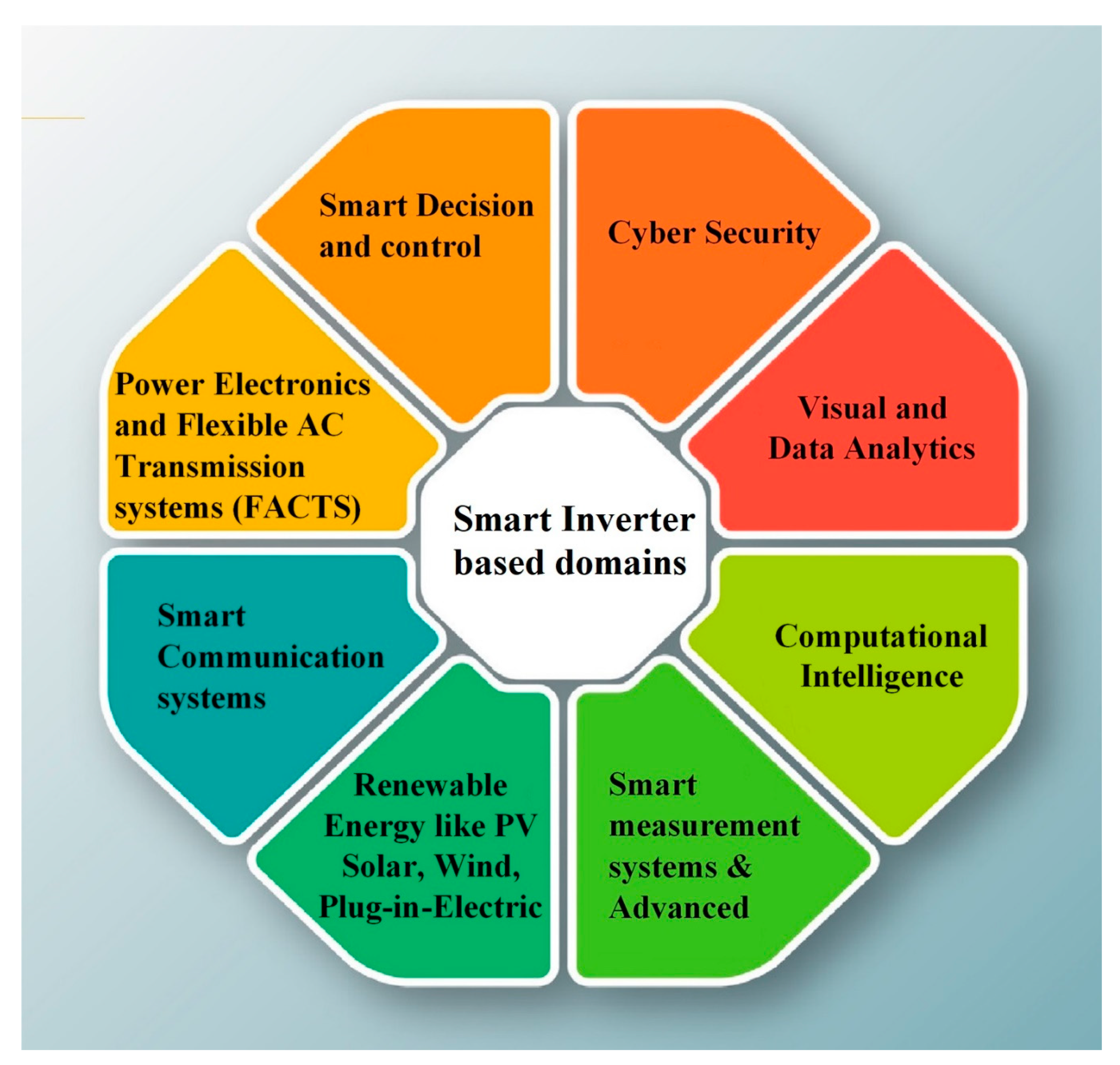
2. Efficacy of Smart Inverters

The production rate of renewable energy system is increasing due to the hike in energy consumption. The conventional forms of energy sources that are available in today’s market are like the fossil fuels are detrimental to the environment. These fossil fuels also emit greenhouse gases in the atmosphere and cause global climate change. To overcome the drawbacks, electricity can be generated from pure form of energy sources such as solar, wind, hydro, etc., called as renewable energy and also from plug in electric vehicles (PEVs) based on the charging and discharging schemes.
Among the various renewable energy sources, PV is the most commonly used energy source. This is due to the fact that, the solar energy is clean, pollution free and reliable in nature. Since the output of solar panel is DC, a power electronic device (inverter) is required to interface it to the grid system. A conventional inverter can do the conversion process of DC to AC. Nowadays, inverters with smart features are preferable in distributed generation interface. It is one of the efficient ways to achieve stability in the grid side network [17]. The demand for smart inverters is expected to grow at the highest CAGR (compound annual growth rate) in the Asia Pacific region due to expansion in solar energy capabilities in countries such as China, Pakistan, Japan, India and Australia among others. The regional analysis of smart inverter utilization by world share market is shown in Figure 2.
PV/PEV generates DC power which is fed to a common DC bus. This DC power needs to be converted to AC power. Presently, bidirectional voltage source converters/voltage source inverters are used for the conversion process and then they are synchronized with the main AC grid. Figure 3 presents the same with different distributed energy resources. There can be several inverters independently for DERs or a centralized inverter for the DC power coming from various DERs.
It could be seen from Figure 3 that when the exchange of real power from battery energy storage systems (BESS), PV and PEV are not present, the inverter is going to be dormant. Sometimes even when real power is being generated from various DERs in Figure 3, the full capacity of the inverter is not utilized. With a specialized controller for the inverter, traditional inverters are referred to as intelligent hybrid inverters. Such dexterous efficacious exertion of hybrid inverters as smart inverters can inject or absorb reactive power (VAR) with the main grid. The effective utilization of such dormant traditional inverters as smart inverters will have a major role to play in a smart grid environment.
One such configuration is explained by the authors in [18], which controls the smart inverter in three ways by making the PV inverter to act as dynamic reactive power compensator called STATCOM. The first mode of operation is the basic one, i.e., Full PV mode in which the real power is extracted based on irradiation level. The next one is Partial STATCOM mode where the inverter utilizes the extra power obtained after real power generation for the purpose of voltage and reactive power control. It can also be used for the power factor correction. The final mode of operation is the Full STATCOM mode which can be utilized during some fault conditions and fluctuations.

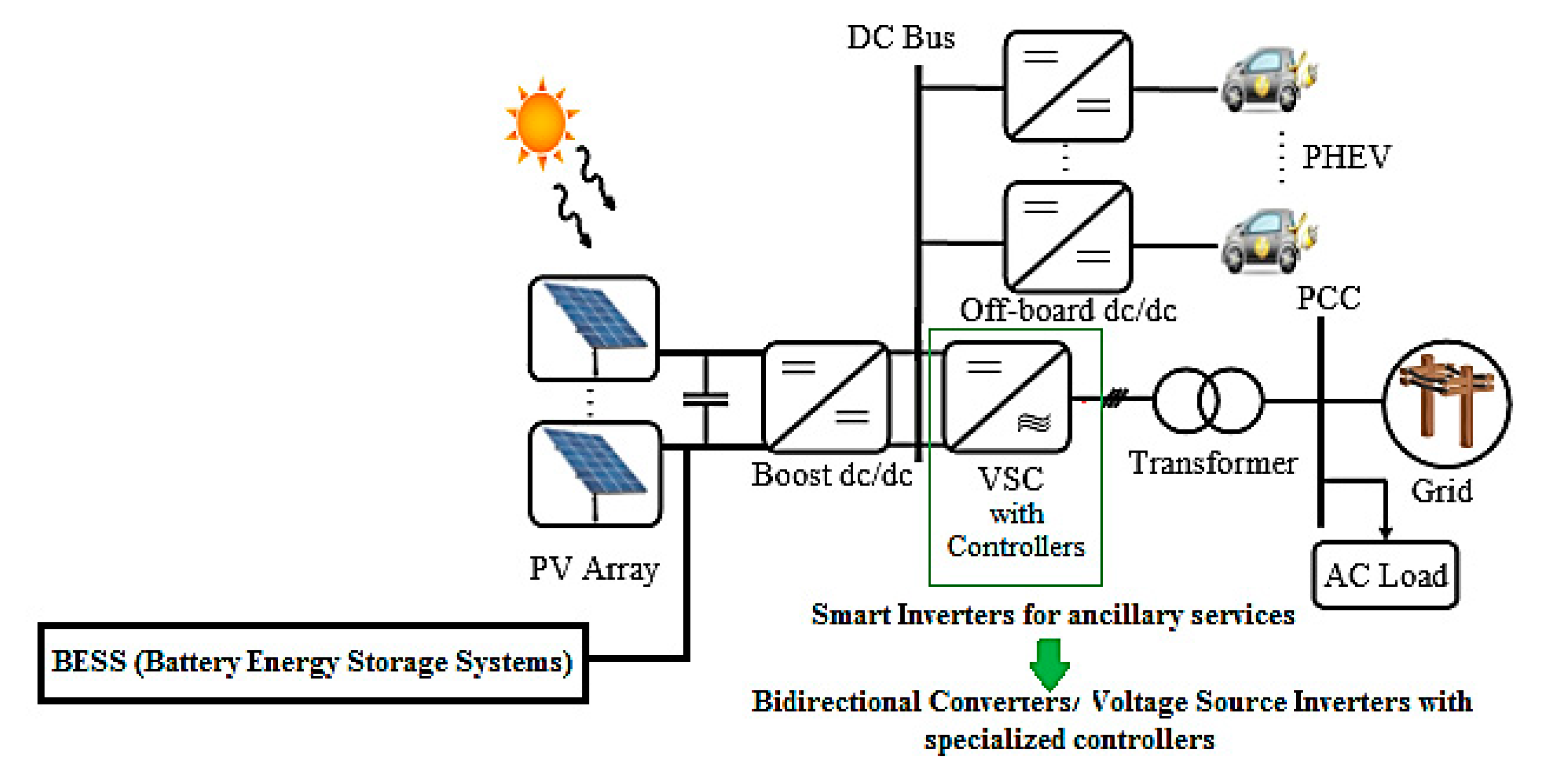
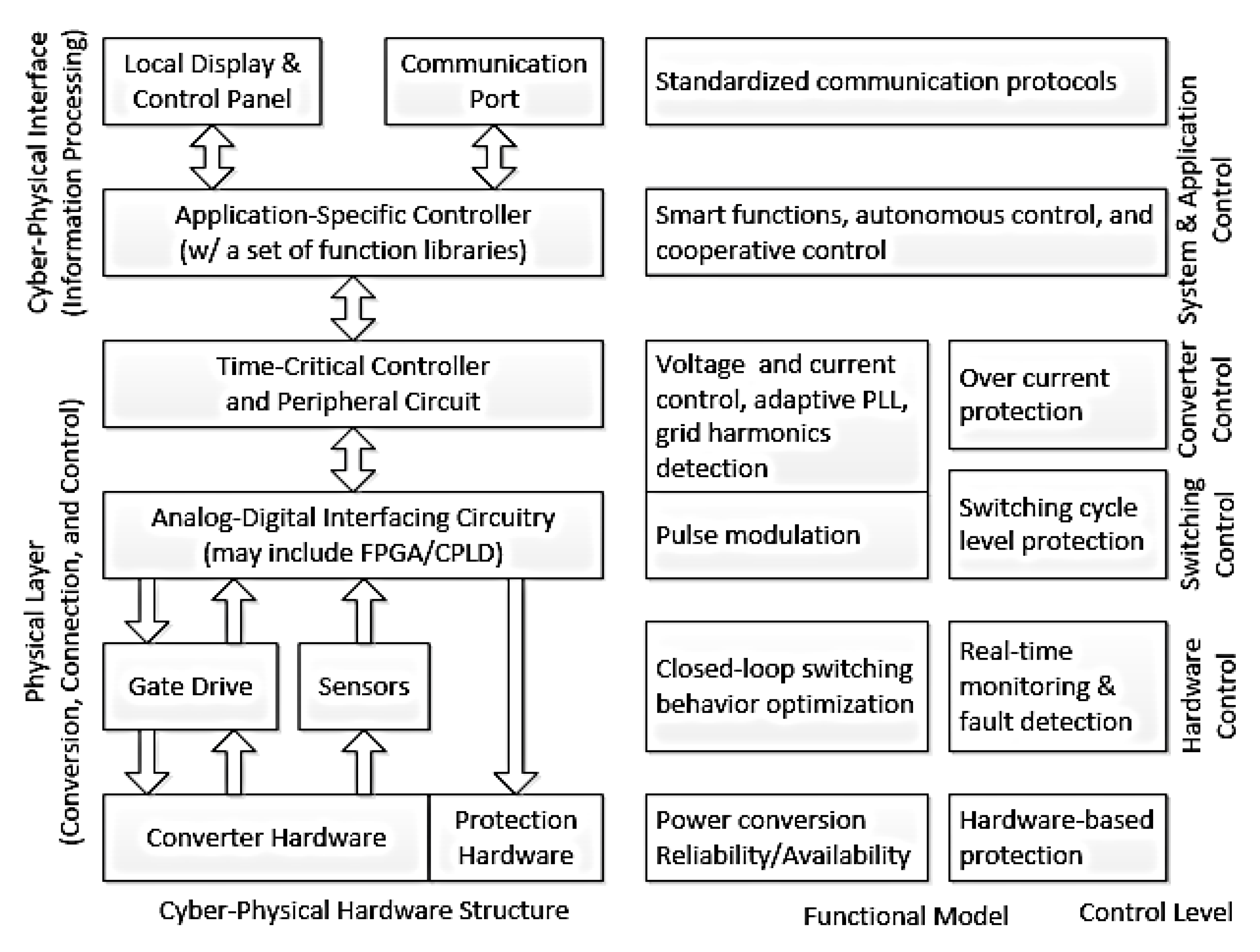
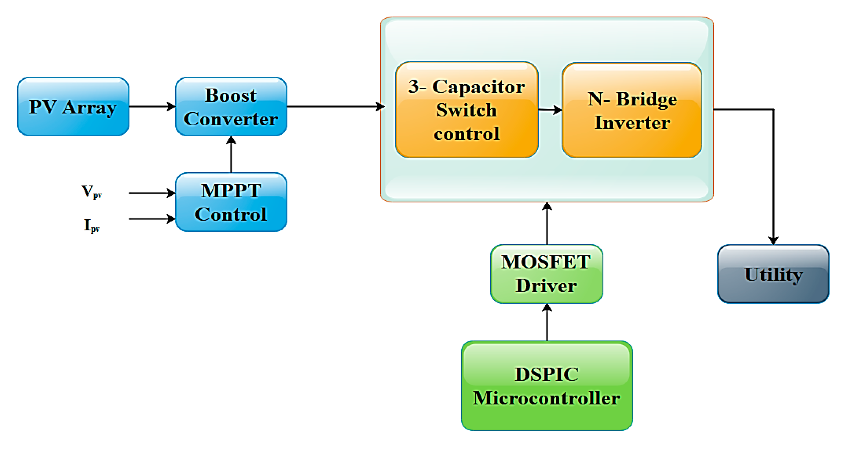
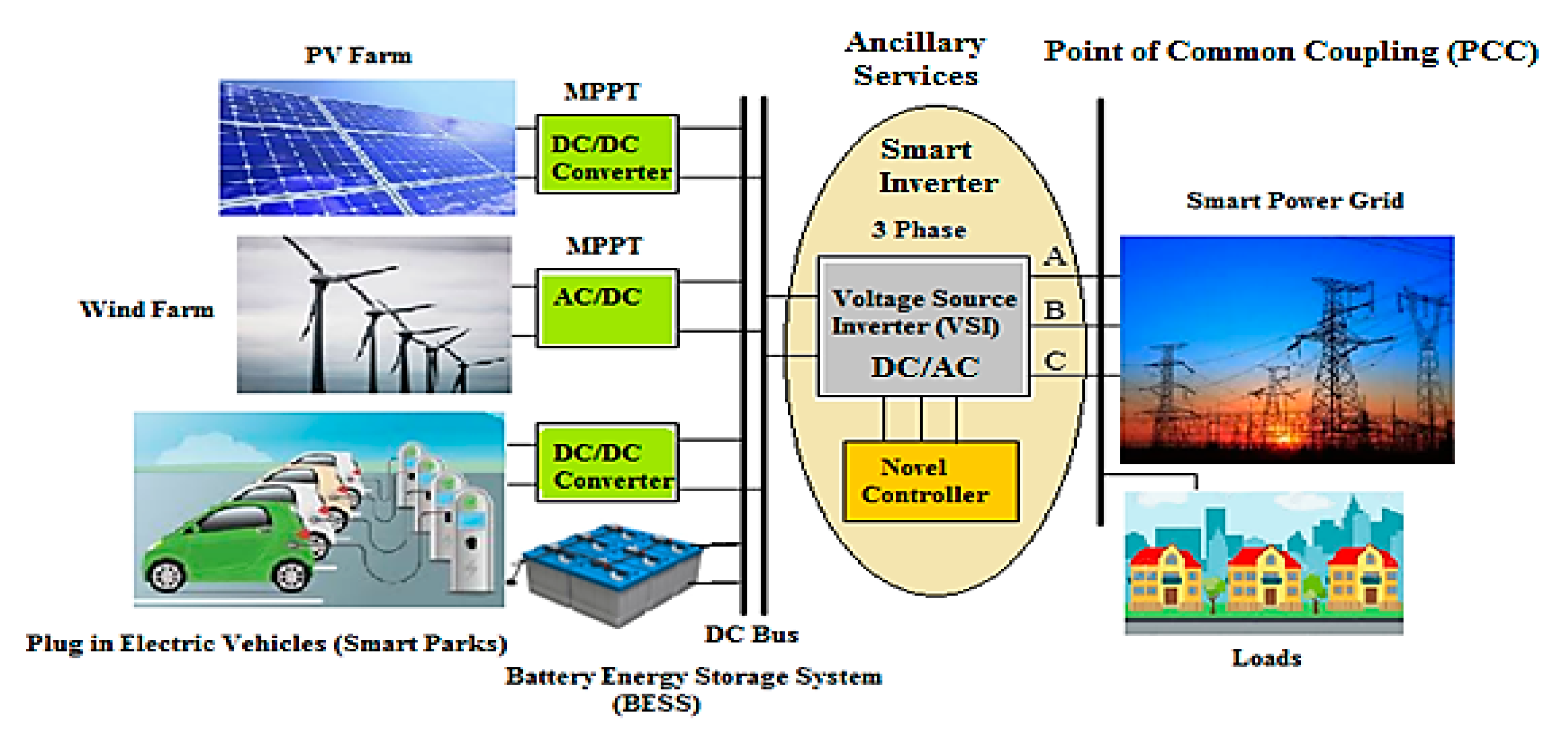
General Hardware Structure of Smart Inverters

The physical hardware and the control structure are the two important components which have to be analyzed, while employing the smart inverters in industrial sectors. The control system of a general smart inverter includes a cooperative controller, an autonomous controller and an optional transactive controller for receiving the regional, local and global information, respectively.
On the other hand, the general structure of hardware includes display units, ADC (analog-to-digital) interfacing circuits, communication ports and several sensors and gate drivers. The block diagram of the control block and the hardware are shown in Figure 4 and Figure 5, respectively.

3. Basic Principle of Operation of Smart Inverters

The basic principle of operation of a smart inverter is similar to a static synchronous compensator (STATCOM) where it could operate in an inductive mode or a capacitive mode. The basic schematic of PV–STATCOM is shown in Figure 6. The smart inverter can act as a static synchronous compensator by performing the following operations [19].
When the insolation from the sun is high, the entire capacitor of the inverter is utilized for real power generation alone. The PV–smart inverter STATCOM can operate in three modes, namely:
(a)
Full PV/Real power mode: The PV–smart inverter STATCOM system generates only real power and zero reactive power. It can also be referred to as the smart inverter working at a unity power factor mode when interfaced with the grid. This is similar to the operation of conventional PV system.
(b)
Shared smart inverter mode: The capacity of the inverter is shared for real and reactive power exchange. The PV–STATCOM supplies real power and the remaining capacity are utilized for reactive power control.
(c)
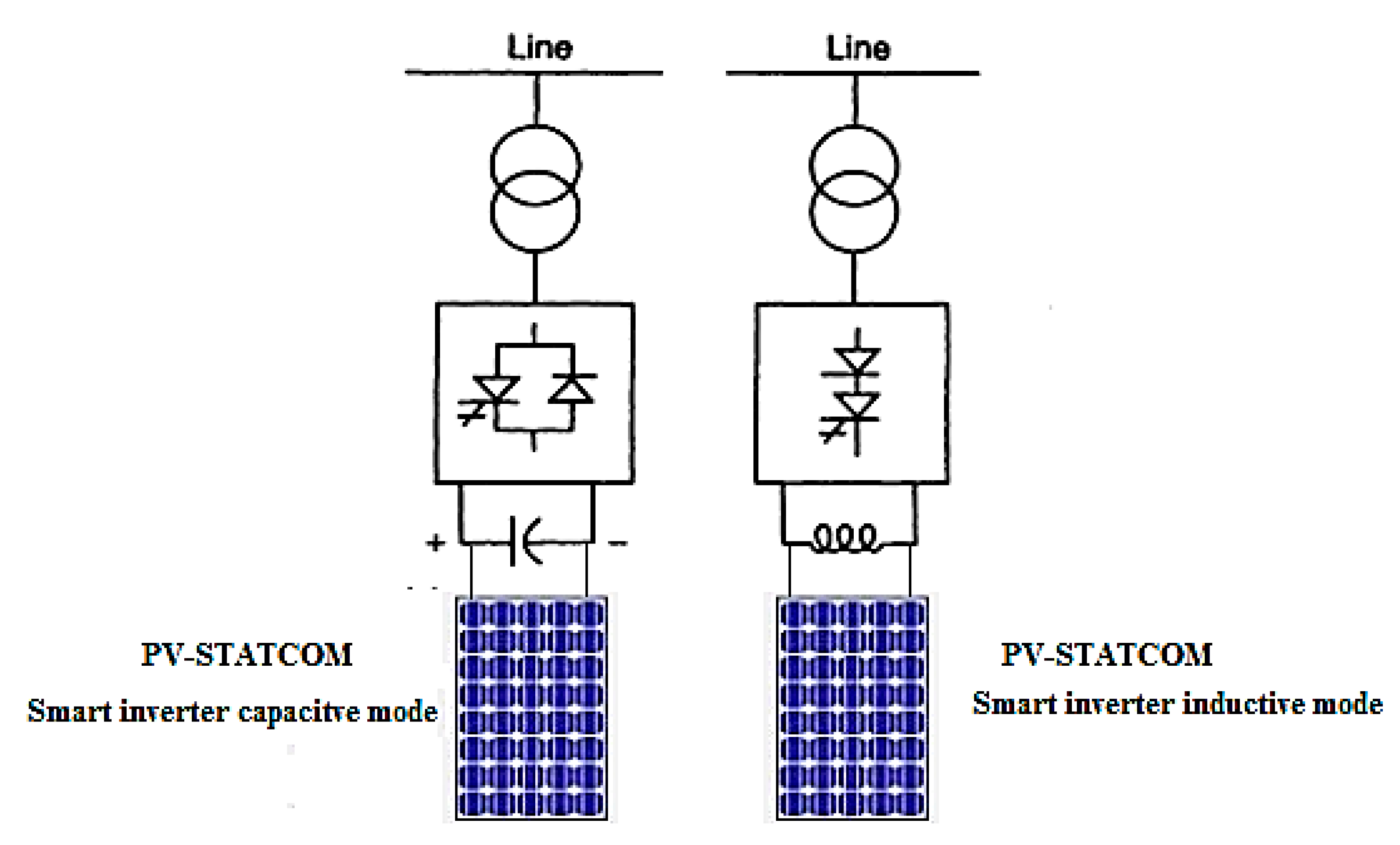
Full STATCOM/VAR mode: The entire capacity of the inverter is used exclusively for reactive power injection and absorption. In other words, a novel controller is effectively exercised in the smart inverter mode for injecting/absorbing VAR at full capacity of the inverter for ancillary services during capacitive/inductive modes, respectively are shown in Figure 7.

4. Basic Controller Concept of Reactive Power Compensation Associated with Smart Inverters

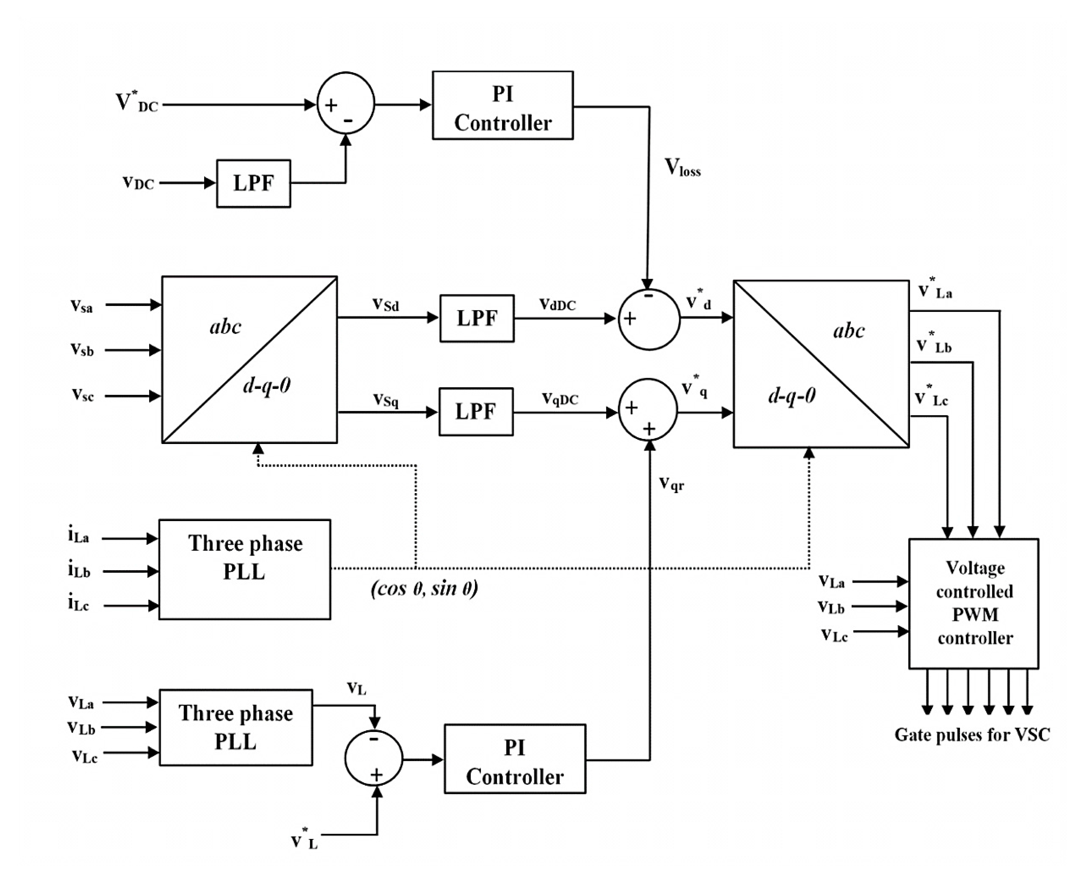
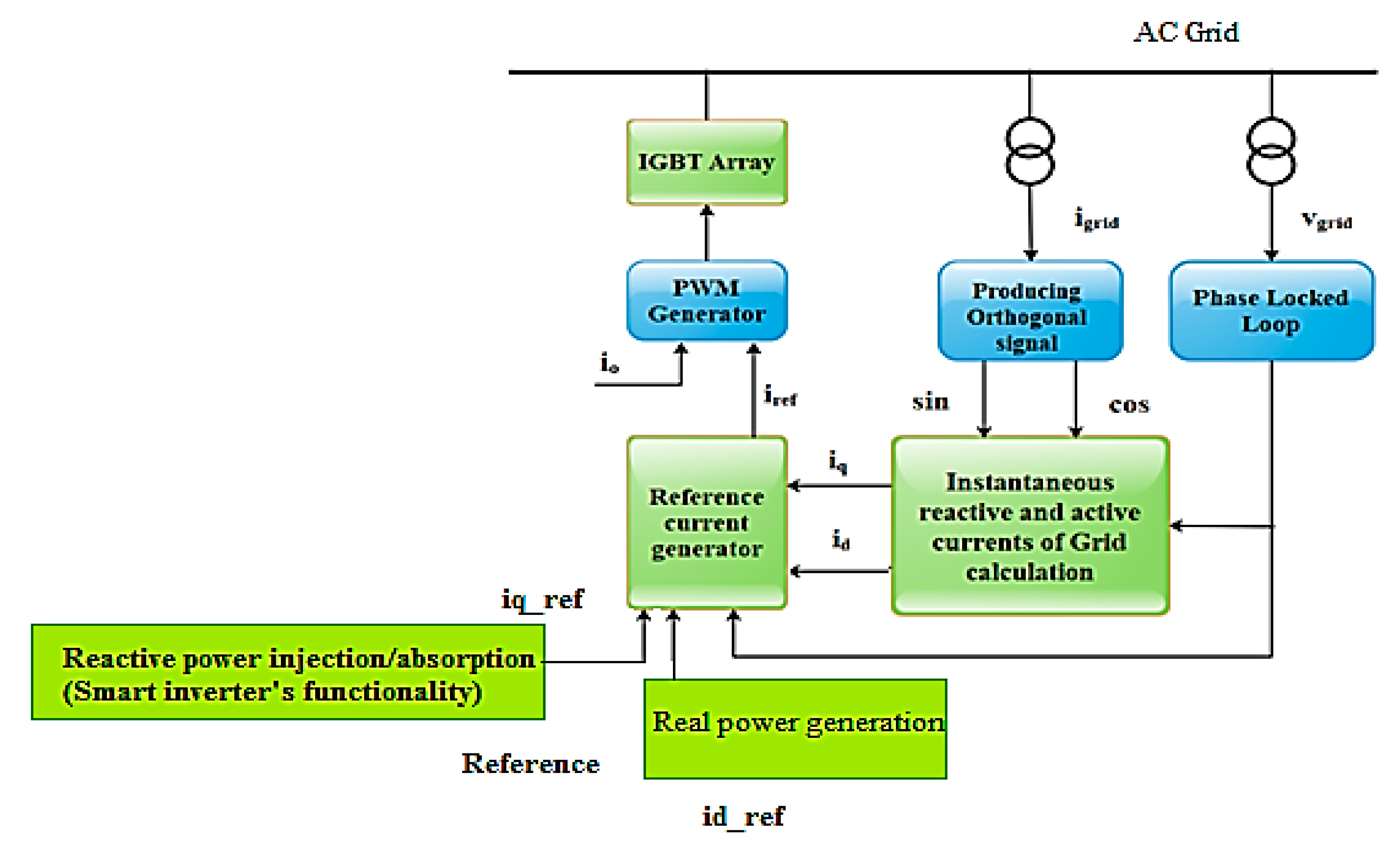
4.1. PWM Based Control Strategy Based on dqo Theory

In this section, the major control techniques for compensating the reactive power are discussed. In the first control method, based on the instantaneous active and reactive power theory (i.e., d-q theory) the output current of an inverter is decomposed into two components. The instantaneous reactive current of the decomposed quantity is adjusted in order to achieve the domestic reactive power compensation. Initially, the load currents are sampled from the grid by orthogonal trigonometric function using a second order generalized integrator (SOGI). Then, the current is decomposed by means of d-q theory and the reactive current is yielded. A reference current is generated (decomposed active current) and compared with the output current of the inverter. Finally, a pulse width modulation (PWM) signal is generated and fed to the controller of the inverter configuration. The block diagrams of the above process are shown in Figure 8 and Figure 9. The reactive power compensation can also be done using certain user defined topologies as discussed in [20,21,22]. In [23], a single-phase circuit with mono-phase PV system is connected to the grid for injecting active power as well as for compensating reactive power. The smart control strategy can be associated with single and three phase inverters as well [24]. Reactive power compensation in residential areas can be easily carried out by interconnecting several PV systems and it is also connected to the distribution network for evaluating various parameters in the aspects of reliability and availability of the systems.
The voltages at the point of common coupling—PCC ( v S ) are converted to the rotating reference frame using the abc–dq0 conversion using the Park’s transformation. The harmonics and the oscillatory components of the voltages are eliminated using low-pass filters (LPFs).
The amplitude of the load voltage ( v L ) at PCC is calculated as
V L = 2 3 ( v L a 2 + v L b 2 + v L c 2 )
[ v L d v L q v L 0 ] = 2 3 [ cos θ sin θ 1 2 cos ( θ 2 π 3 ) sin ( θ 2 π 3 ) 1 2 cos ( θ + 2 π 3 ) sin ( θ + 2 π 3 ) 1 2 ] [ v L a v L b v L c ]
The components of voltages in d- and q-axes are
v S d = v d D C + v d A C
v S q = v q D C + v q A C
The compensating strategy for compensation of voltage quality problems considers that the load terminal voltage should be of rated magnitude and undistorted in nature.
In order to maintain the DC bus voltage of the self-supported capacitor, a PI controller is used at the DC bus voltage of the DVR and the output is considered as the voltage loss v l o s s for meeting its losses
v l o s s ( n ) = v l o s s ( n 1 ) + K p 1 ( v d e ( n ) v d e ( n 1 ) ) + K i 1 v d e ( n )  
where v d e ( n ) = v D C * v D C ( n ) is the error between the reference DC voltage v D C * and sensed DC voltage v D C at the nth sampling instant. K p 1 and K i 1 are the proportional and the integral gains of the DC bus voltage PI controller.
Therefore, the reference d-axis load voltage is
v d * = v d D C v l o s s
The amplitude of the load terminal voltage ( v L ) is controlled to its reference voltage ( v L * ) using another PI controller. The output of PI controller is considered as the reactive component of voltage ( v q r ) for voltage regulation of load terminal voltage. The amplitude of the load voltage ( v L ) at PCC is calculated from the AC voltages ( v L a , v L b ,   v L c )
Then, a PI voltage controller is used to regulate this to a reference value as
v q r ( n ) = v q r ( n 1 ) + K p 2 ( v t e ( n ) v t e ( n 1 ) ) + K i 2 v t e ( n )
where v t e ( n ) = v L * v L ( n ) denotes the error between the reference load terminal voltage ( v L * ) and actual load terminal voltage v L ( n ) amplitudes at the nth sampling instant. K p 2 and K i 2 are the proportional and the integral gains of the DC bus voltage PI controller.
The reference load quadrature axis voltage is
v q * = v q D C + v q r
The reference load voltages ( v L a * , v L B * , v L C * ) in abc frame are obtained from the reverse Park’s transformation. The errors between the sensed load voltages ( v L a , v L b ,   v L c ) and reference load voltages are used in the PWM controller to generate gate pulses for the VSC.

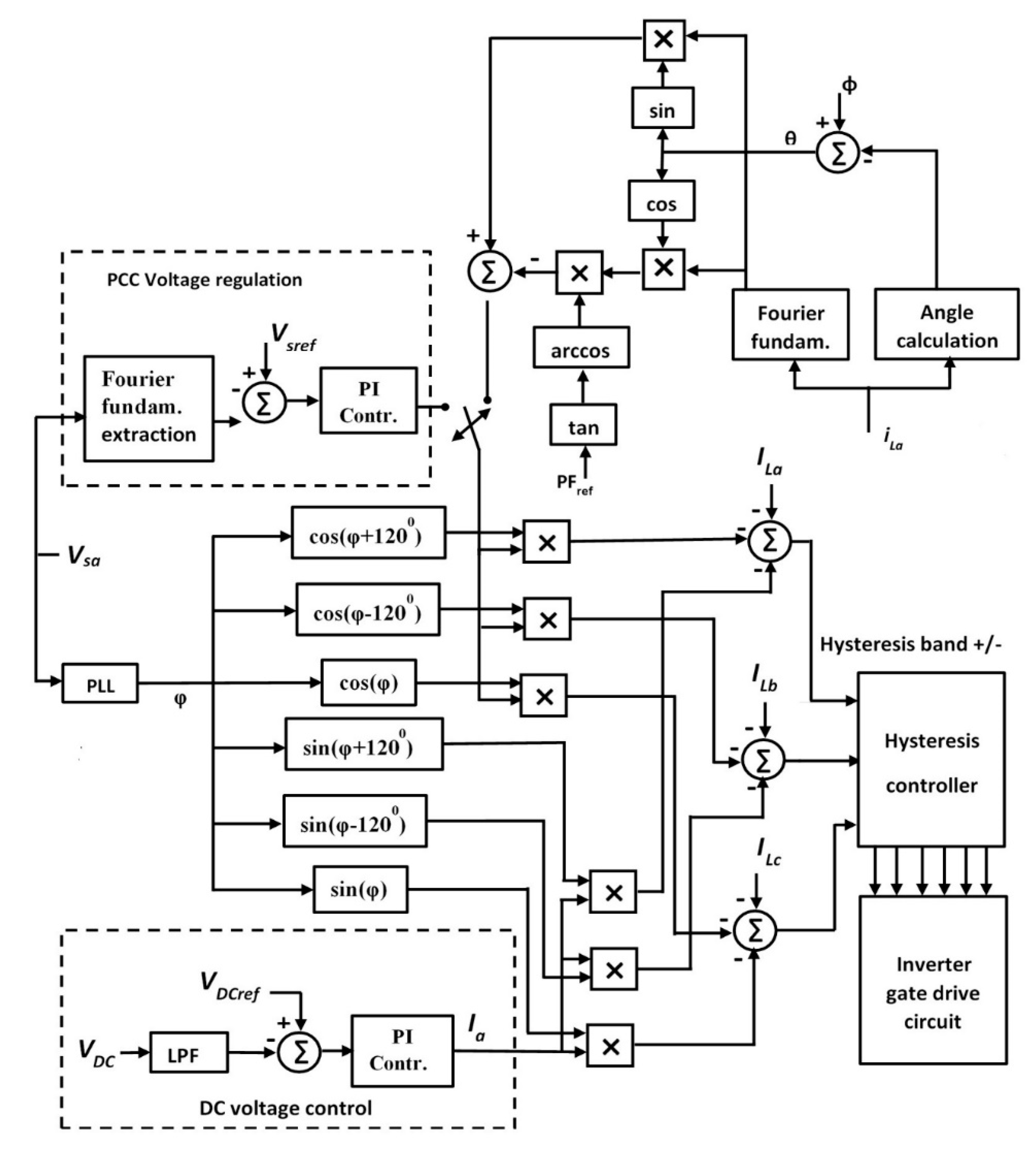
4.2. Hysteresis Based Current Controlled Modulation Technique or Bang–Bang Control

Figure 10 presents a block diagram of control strategy for a smart inverter in a current control mode, based on the hysteresis control modulation technique. The active and reactive component of the current determines the amount of real power and reactive power exchange. A Proportional Integral (PI) based control parameters are fine-tuned using Ziegler–Nichols tuning rules and then refined through simulations. A phase locked loop (PLL) circuit is used for synchronizing the inverter with the main grid at the point of common coupling (PCC).

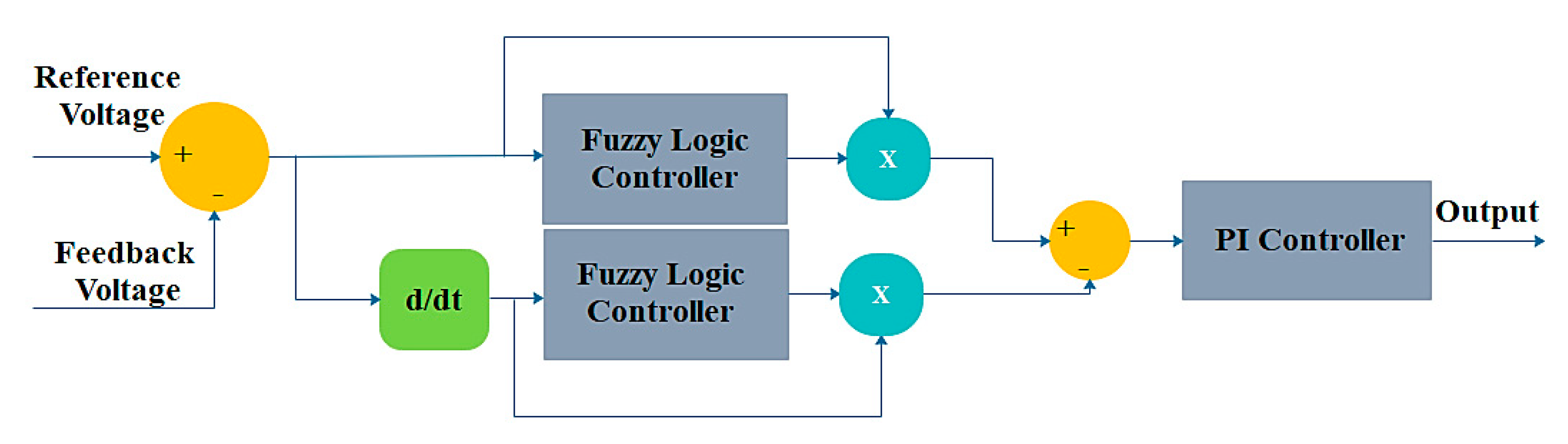
4.3. Fuzzy Based Hybrid Control for Smart Inverters

Fuzzy logic control is an intelligent control technique based on human reasoning. It can be used in a smart way to perform the required ancillary service related to the grid. The authors have proposed a hybrid control design based on fuzzy logic to improve the voltage profile of the inverter output. The same control could also be adopted for reactive power exchange. This control is a combination of conventional PI controller along with a fuzzy controller based on different rules that were formulated. The results served to be better compared to that of conventional controllers. The functional block of hybrid controller that could be associated with smart inverter is shown in Figure 11.
The controllers of smart inverters could be classified according to four major functionalities.
(i)
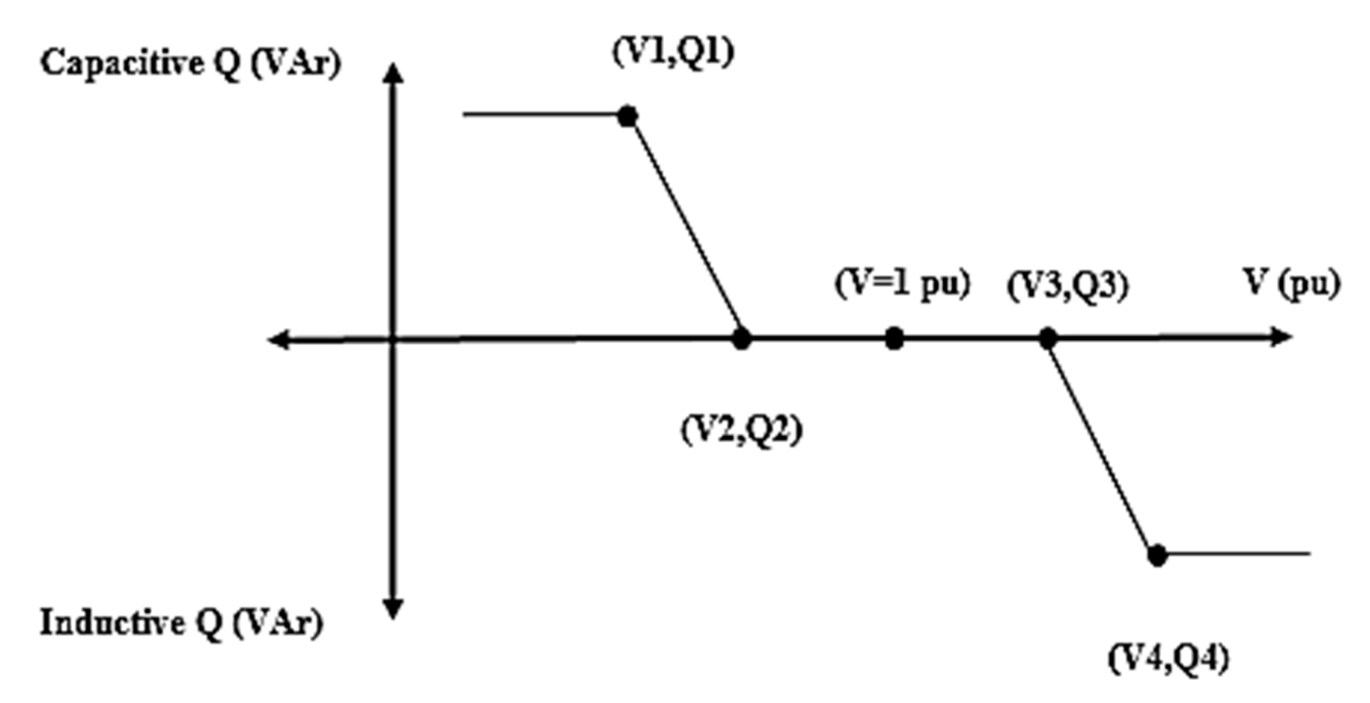
Volt/VAR control mode: This mode purely represents the regulation of AC voltage by controlling the VAR that is exchanged with the system (injection or absorption). The Volt/VAR control mode has a droop-based Volt/VAR curve as shown in Figure 12.
It could be seen from Figure 12 that the smart inverter could be made to operate in one of the operating regions. (a) Linear region with reactive power injection (capacitive) (region between points (V1,Q1) and (V2,Q2)) (b) Linear region with reactive power absorption (inductive) (Region between points (V3,Q3) and (V4,Q4)) (c) Dead band region with zero reactive power injection/absorption (Region between points (V2,Q2) and (V3,Q3)) (d) Saturation region with constant reactive power injection (Region after (V1,Q1)) (e) Saturation region with constant reactive power absorption (Region after (V4,Q4)). A smart inverter based on its control strategy could be made to operate in one of those regions according to the characteristics and requirements of a distribution feeder. The curve can be configured with or without a dead band region based on the required voltage level and reactive power consumption. The slope of linear region of the curve can be decided based on the required reactive power to mitigate the voltage rise caused by active power feed-in of PV systems.
(ii)
Volt/watt control mode: This mode represents the regulation of active power that is being exchanged with the system (injection and absorption).
(iii)
Low- zero/high voltage ride through (LVRT-ZVRT/HVRT): This mode presents the ability of inverter to stay connected without having to disconnect from the system during faults by means of VAR support from the inverter. There is a tendency that the voltage deviations propagate from the transmission levels to the distribution levels which in turn results in tripping of the DERs connected. During such an event, the smart inverters can provide reactive support without having to disconnect from the system.
(iv)
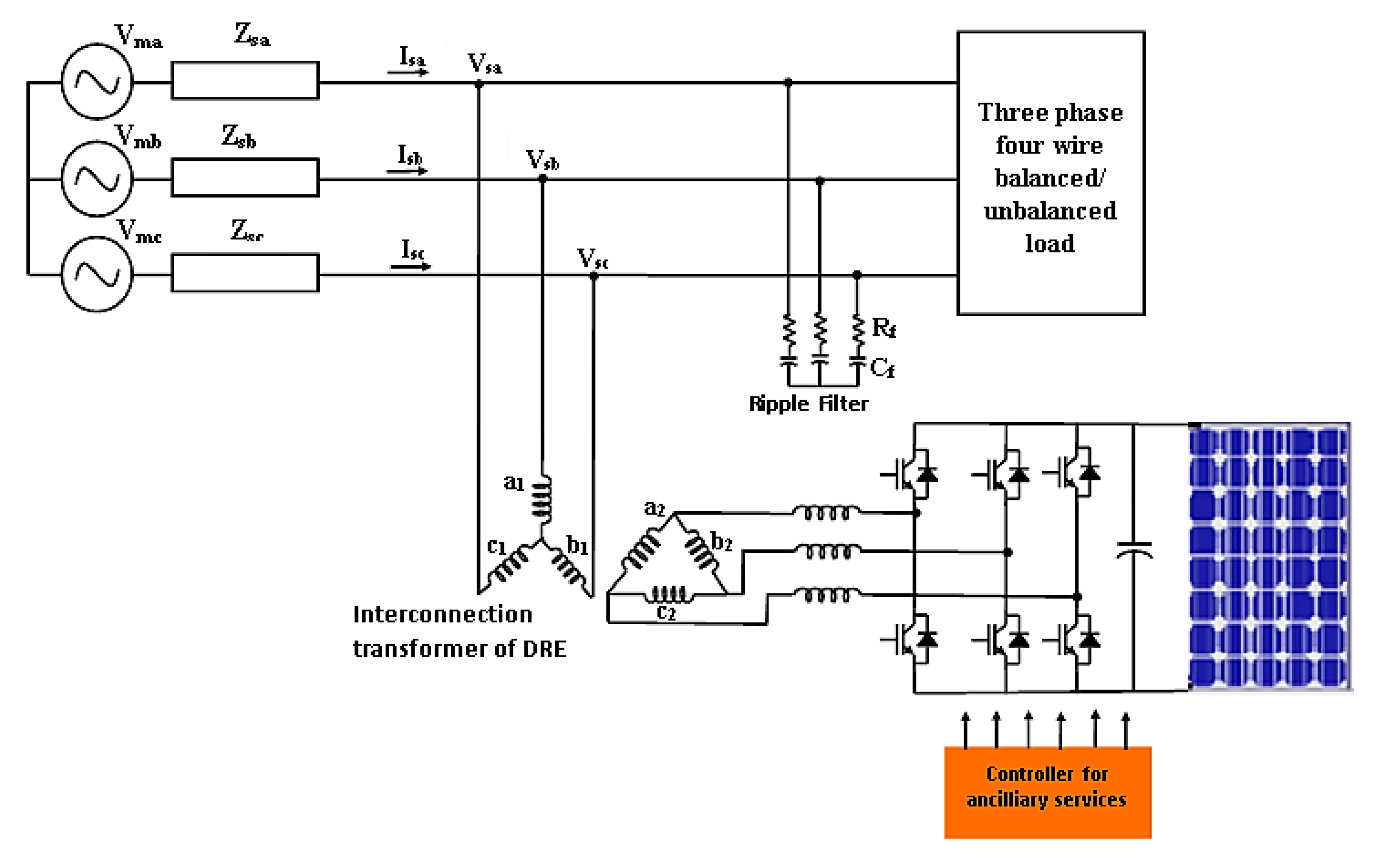
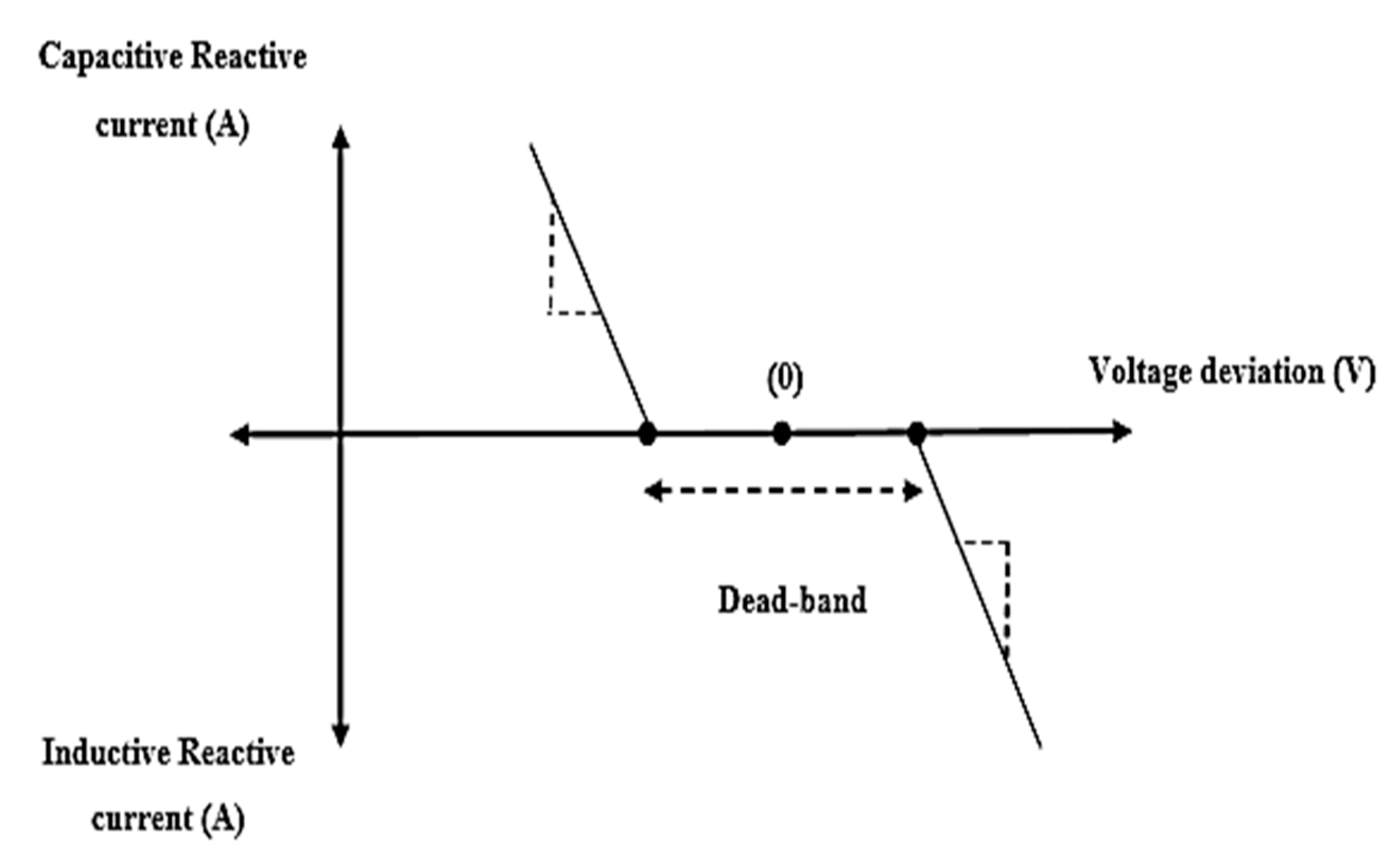
Dynamic reactive current injection: The injection and absorption of reactive current of the inverter forms the basis of dynamic reactive current injection mode. The dynamic variations in the system voltage such as voltage flicker, voltage support during LVRT/ZVRT, require a suitable reactive compensation. Such compensation could be provided by means of dynamic reactive current injection from the inverters of DERs when they are dormant, by making use of its available capacity for such ancillary services. In case of a situation when the inverters are fully utilized for injecting active power, certain amount of real power could be curtailed for using making use of the inverter for reactive current injection. The controller that is associated with the smart inverter employed in Figure 9 utilizes such dynamic current injection technique. Both the active and reactive currents could be controlled separately. This is utilized in conjunction with other steady state reactive power controls. The operating modes during dynamic current injection are shown in Figure 13. The slope of the curve determines the magnitude of capacitive or inductive reactive current injected for a particular voltage deviation.
The dead band is a region where no reactive current support is exerted from the smart inverter. Dead-band arises when the valve needs to change direction. To avoid the dead-band, an additional output needs to be sent by the controller to overshoot its target position. In case if smart inverter, defining a dead band is highly essential to limit the D-STATCOM action in the unnecessary situations and only use it in the extreme voltage violations. This system control has a function of keeping the output of the reactive power to a minimum value—and if the reactive power from smart inverter is outside a dead-band for a specified time—a control action is initiated for controlling the reactive power.

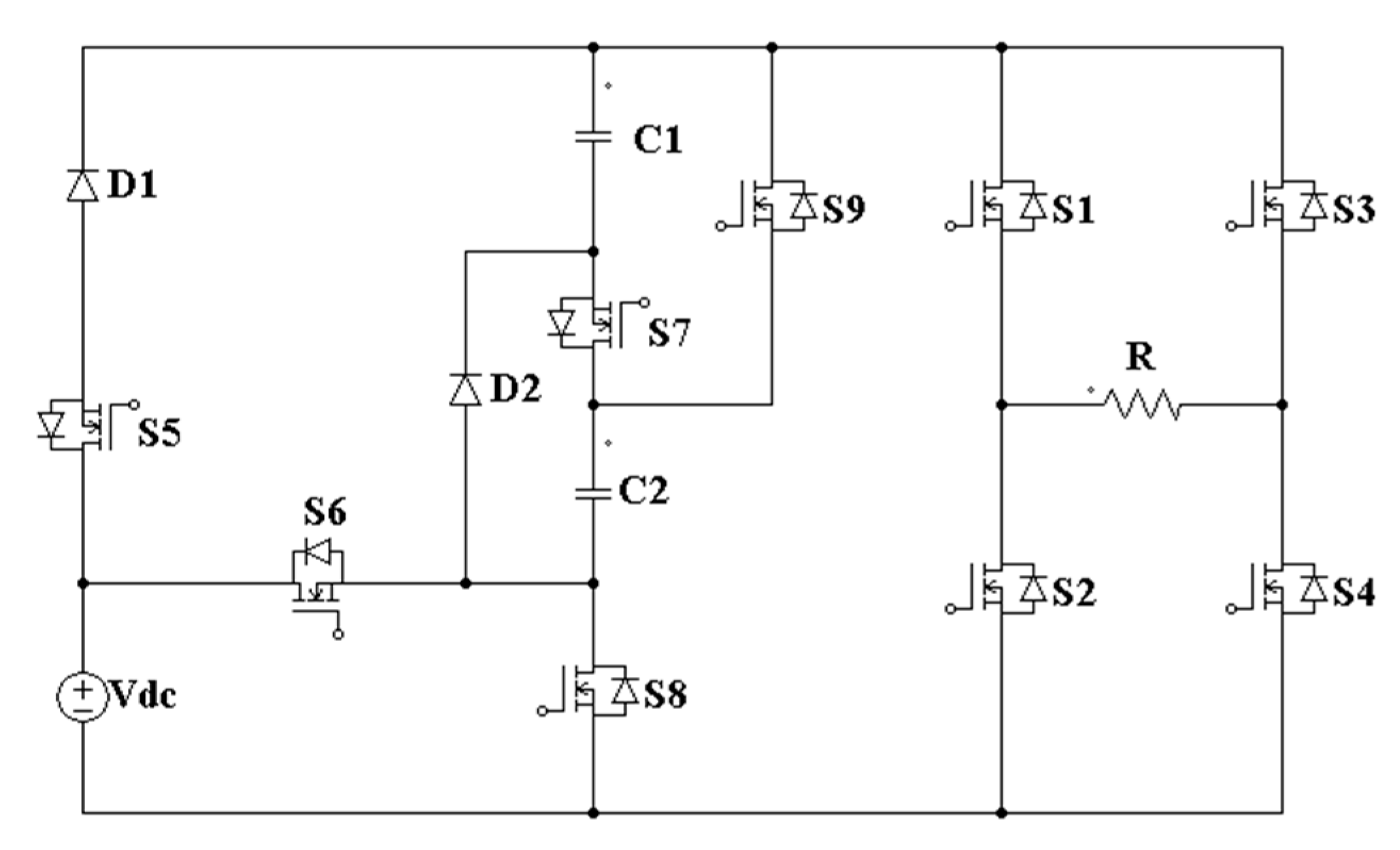
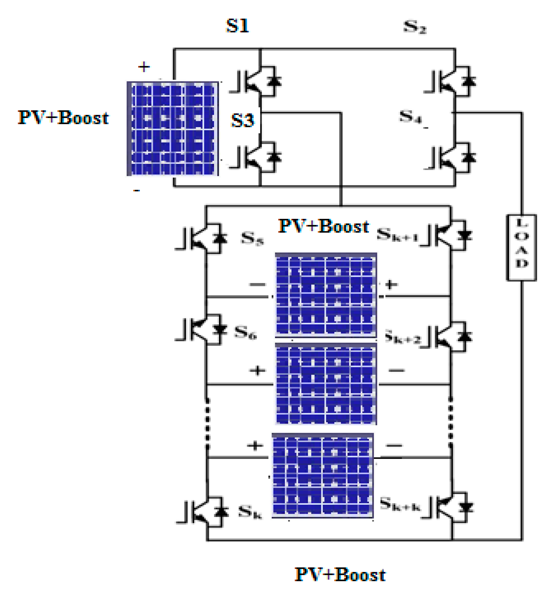
5. Multilevel Hybrid Smart Inverter Based on Topology

By employing one of the discussed control strategies, a multilevel smart inverter can also be used more effectively. A multilevel inverter (MLI) can act as a smart inverter by making some changes in the control system of the inverter topology. Apart from that, the topology associated with the inverter also determines the hybrid and intelligent performance of the inverter. A modified hybrid multilevel inverter with reduced number of switches is proposed in [25,26,27,28,29,30,31]. Here, IoT is employed for the control of MLI which provides the smart attribute to its functionality. A nine-level inverter parameters are scrutinized by a pair of IoT widgets, settling measures and the combined ascribe of an IoT gadget on the packages (bundles) not comparable of the addressed contiguous region, the inactivity of packages in addressed close-by zone and the separation of IoT gadget to the goal gadget. Employing these attributes, the change probabilities for the associations can be found. The overall system is shown in Figure 14.
A novel MLI configuration is proposed in delivers a nine-step output voltage with high voltage gain. It consists of a developed switched capacitor circuit (DSCC) at the frontend of the inverter and another circuit is a conventional H-bridge circuit. The H-bridge circuit connected at the backend of the inverter is used for producing the negative voltage levels of the output. The circuit configuration of multilevel inverter is shown in Figure 15.
To maintain a high voltage profile, an intelligent control technique can be used to control the operations of the multilevel inverter. In this paper, the authors have proposed a circuit by integrating a full bridge inverter and combination of switched DC sources. The generalized circuit diagram of the proposed hybrid MLI is shown in Figure 16.
This hybrid configuration can be extended to high number of output voltage levels by adding corresponding switches and DC sources. The SDCS design operates in asymmetric manner in order to increase the voltage level at the output side. The authors have already demonstrated a neoteric fuzzy controlled stratagem of a MLI for enhanced output voltage applications for interfacing Plug in electric vehicles (PEV).
With more smart inverters in place including multilevel smart inverters that are associated with renewable energy resources and Plug in electric vehicles, the loading effects of the smart inverters needs to be investigated as well. For such high-power and /or low-cost applications, the high current power electronic devices needed to be connected in parallel. In a distribution utility network, the inverters are connected in tandem to provide a high reliability and redundancy. The most significant problem that would arise during such parallel connection of inverters is loading effects. The load sharing forms an important crux of such smart inverters in place. A key technique to remove the loading effects of the smart inverters is to employ a droop control, which is widely used in conventional power generation systems. The merit that is associated is that no external communication mechanism is needed among the inverters. Though significant progress has been made for equal sharing of linear and nonlinear loads, sharing the loads on an accurate basis in proportion with the rating of such smart inverters still may pose a challenge. The reactive power sharing is not high in terms of accuracy. Another issue is that the output voltage drops due to the increase of the load and droop control. Hence, an addition of integral action to the droop controller has improved the accuracy of load sharing for grid-connected smart inverters including multilevel inverters. To reducing the loading effect on inverters, it should have the same per-unit impedance so that the inverters that are connected to in parallel are not overburdened with loading and could share the load based on the rating of the smart inverters. It also requires that the RMS voltage set-points for the inverters to be the same. Both are very strong conditions. Such a robust droop control with an integral action can regulate the output voltage to reduce the effect of the load and droop control on the output voltage.

6. Functions of Smart Inverters

The additional capabilities of PV/PEV inverters that can be used to solve some of the issues due to increased penetration of distributed energy resources are called “smart functions” and such an inverter is called smart inverter. As a result of increase in smart inverters, the ultimate aim is to minimize some of the reinforcement measures in the grid that are expensive. The role of smart inverters surpasses the basic functions of conventional inverters, such as maximum power point tracking, islanding detection and power conversion. With the existing infrastructure of the power grid, with the help of smart inverters, it facilitates more integration of renewable energy. As the grid is becoming smarter day by day, the focus towards issues such as reverse power flow, power quality aspects such as flicker, harmonic distortion and resonance, voltage stability, frequency stability and overall reliability of the system has become the need of the hour that needs to be addressed. With the increased penetration of DERs in smart grid, it allows the bidirectional flow of power unlike the conventional power system that permitted only unidirectional flow of power. As a result, a steady rise in voltage could be witnessed on the system where the DERs are interfaced at the point of common coupling [32,33,34,35,36].
Smart inverters in the VAR mode can regulate such sudden voltage rise by means of VAR injection and absorption thereby limiting the voltage levels within the permissible limits of the system. This facilitates increased penetration of DERs in a smart grid environment [37,38,39,40,41,42,43,44,45,46,47,48,49,50,51,52,53]. The problem of reverse power flow could be mitigated thereby serving as an important aspect in solving the protection schemes without tripping the circuit breakers due to reverse power flow. The interconnection of PV also leads to power quality issues like voltage flicker, harmonic distortion and resonance. Smart inverters with its specialized controller can act as an Active power filter (APF) to mitigate these harmonics. Further with a help of a specialized controller scheme, a smart inverter can also act as a virtual detuner in mitigating network harmonic resonance. According to IEEE 519 Standard, the network resonance and harmonic distortion go hand in hand with each other. Smart inverter can play a vital role in that case. Further, in a three-phase distribution system, the loads are unbalanced. A smart inverter also performs the role of load balancing. For the stable and reliable operation of the grid, several research groups and companies like the Electric Power Research Institute (EPRI) and California public utilities commission has created the working groups associated with smart inverters (SIWG) for mandating standards for advanced inverter technologies. Further recommendations were made from the Society of Automotive Engineers (SAE) for operating and controlling plug in hybrid electric vehicles with respect to the charging procedures and stability aspects while interacting with the grid.
Fault Ride-Through (FRT) is defined as the ability of a grid-tied inverter to stay connected to the power system and withstand momentary deviations of terminal voltage that vary significantly from the nominal voltage without disconnecting from the power system. Since the most likely cause for excessive voltage deviations in a power system is a fault in the system, the term “fault ride-through” is sometimes used in case of a scenarios when a reactive power support is required. In contrast to reduced terminal voltage, a fault event on power systems with specific characteristics may also cause a momentary rise in voltage. Momentary voltage sag is usually caused when there is a fault due to a short circuit or lightning strike that leads to a flow of high current between phases or to ground. This can cause the inverter to trip and disconnect from the power system network until the system is stabilized. The disconnection can produce a ‘domino effect’ by exacerbating the event and causing other inverters to trip. L/HVRT allows inverters to stay connected if such voltage excursions are for very short time durations and the voltage returns to the normal range within a specified time frame. L/HVRT does not require the inverter to stay connected if the fault persists beyond a specified time. With the version of IEEE 1547.8 and UL 1741 Standard, the smart inverter can operate in VAR mode by providing the necessary reactive power support without having to disconnect the inverter.
During an unsymmetrical fault like single line to ground fault and double line to ground fault, the voltage in those faulty phases alone drop to zero. There is a momentary rise in the voltage levels in the healthy phase during such unsymmetrical faults beyond the permissible limits of ±5% in a distribution system. This is known as temporary over voltage (TOV) phenomenon. This could be mitigated by employing specialized controllers associated with the inverter as a smart inverter for suppressing the TOV phenomenon. Apart from performing the voltage regulation in all three phases by the smart inverter, it can also perform power factor correction of the local operating loads.
Normally, the power factor associated with inductive loads like induction motors are somewhere in the range of 0.6–0.75. They are usually supported by capacitor banks for performing the power factor correction so that the loads can operate at a power factor of more than 0.9 to avoid the penalty that are imposed by the utilities. But capacitor banks can cause harmonic distortion and resonance by interacting with the rest of the system. Smart inverters with their specialized controller can effectively perform the role of a capacitor for power factor correction without causing resonance and harmonics in the system.
All the ancillary/augmented services from the smart inverters could be carried when the capacity of the inverter is not utilized fully [54,55,56,57,58,59,60,61,62,63]. Making an effective utilization of such dormant inverters can play an effective role in a smart grid environment. Figure 17 presents the efficacy of a smart inverter during the integration of several DERs. A comparison of the functionalities of conventional Voltage Source Inverter (VSI) and smart inverters are presented in Table 1.

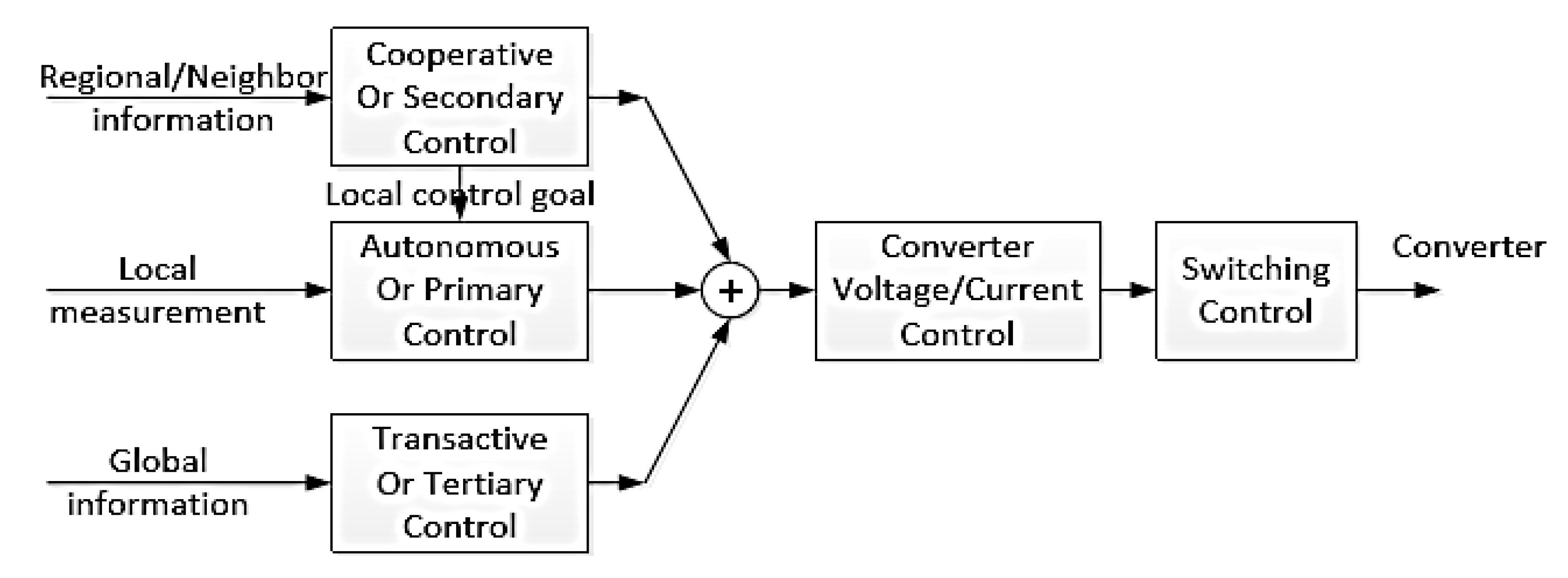
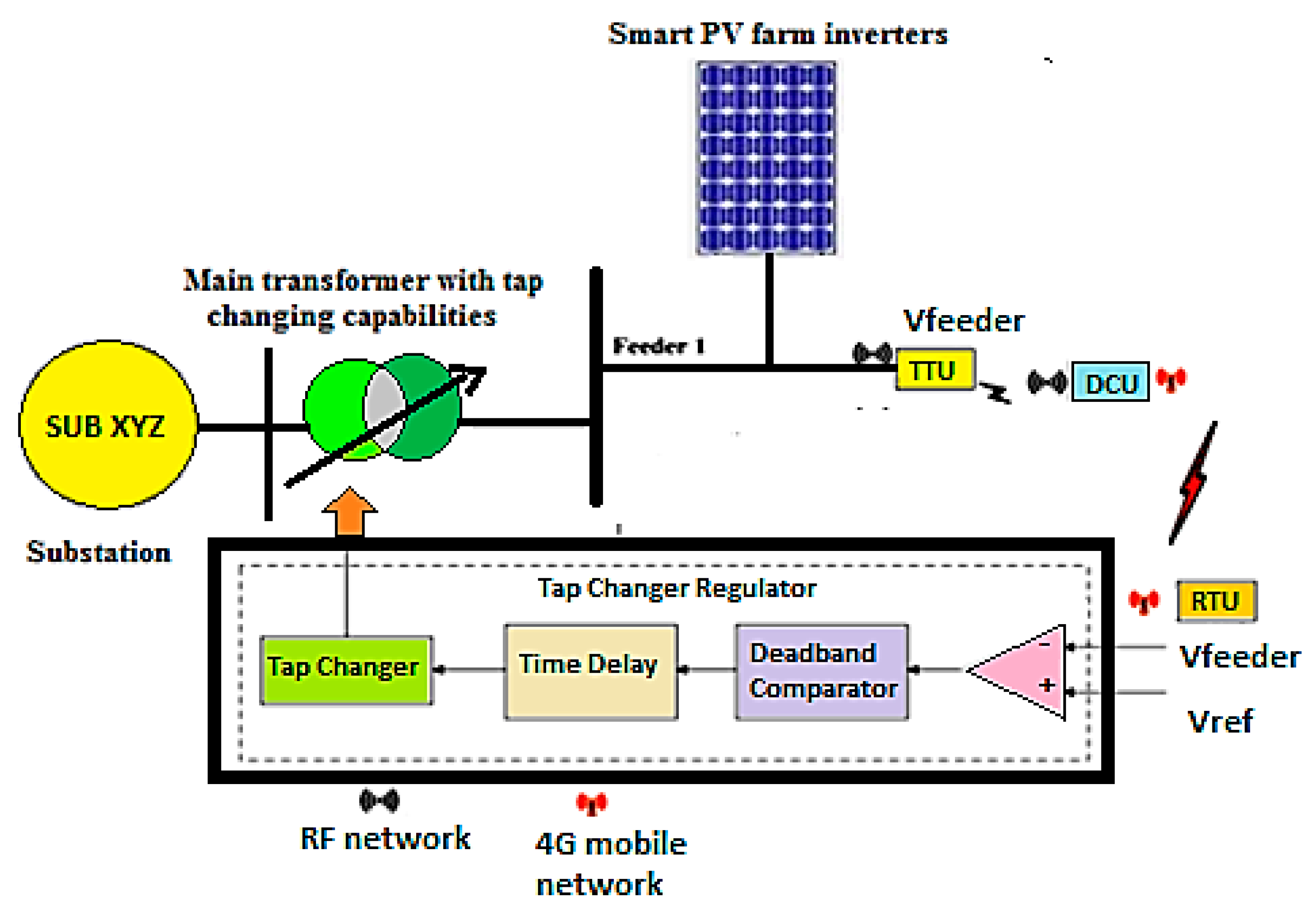
7. Coordinated Control of Smart Inverter with the Distribution System

Apart from the standalone functionalities of smart inverters, they can also very well coordinate with the devices that are installed in a distribution feeder. In case of a radial feeder, the voltage levels normally drops down towards the end of a feeder. Though there are several techniques like implementation of off-nominal transformer configuration, demand side management, reactive power control and so on. But a coordinated operation of smart inverters in a distribution system will be highly effective. Normally to overcome the low voltage on a distribution feeder, an On-Load tap changing transformers are employed. By adjusting the tap settings, the voltage levels are brought within the normal levels of ±5% of the permissible limits. A SCADA system can provide the status of the voltages at the end of the feeders. The details of the injected real power from PV systems and OLTC tap positions are obtained from the profile of the feeder voltage. Based on these details, the OLTC tap changer can adjust its settings. This case is purely when a PV is injecting real power. There can also be a case when PV is not injecting real power and the inverter can be dormant. During such a situation when voltage levels are low or high, the SCADA system transmits the information over the communication network to instruct the OLTC and smart PV inverter system. In this case, the smart inverter can also act like a FACTS device (STATCOM) by suitable reactive power compensation for raising or lowering the voltage levels on the feeder. Further, both OLTC and smart inverters can jointly perform a voltage regulation on a distribution feeder. Figure 18 presents such coordination between smart PV inverters and OLTCs for maintaining the voltage levels on the feeder.

8. Conclusions

Thus, smart inverters are much more reliable and efficient when compared to conventional inverters. A range of operations associated with the grid connected systems such as reactive power compensation, coordination control; novel topologies of smart inverters for grid interconnection are discussed in this paper in the form of a review. It can be further extended with several new controllers and algorithms for obtaining better and accurate voltage profile for grid connected systems. As the penetration levels of DERs have gone up, the need for such ancillary services has grown as well. This paper presented a highly effective solution for utilizing smart inverters for ancillary services in a grid in the form of a review.

9. Future Scope

The research work on smart inverter applications for augmented services in smart grid presented in this paper will serve as a benchmark for several researchers and engineers working in this domain.

Author Contributions

S.S.R., J.S. and C.K.S. equally contributed to this paper by formulating the idea, carrying out the literature review in writing the paper and performed all related actions in shaping up the paper. All authors have read and agreed to the published version of the manuscript.

Funding

The research received no external funding.

Conflicts of Interest

The authors declare no conflict of interest.

References

  1. Rangarajan, S.S.; Collins, E.R.; Fox, J.C.; Kothari, D.P. A Survey on Global PV Interconnection Standards. In Proceedings of the IEEE Power and Energy Conference at Illinois (PECI), Champaign, IL, USA, 23–24 February 2017. [Google Scholar]
  2. Rangarajan, S.S.; Collins, E.R.; Fox, J.C.; Kothari, D.P. Consolidated compendium of PV interconnection standards across the globe in a smart grid environment. J. Energy Technol. Res. 2018, 2, 1–29. [Google Scholar] [CrossRef]
  3. Varma, R.K.; Rangarajan, S.S.; Axente, I.; Sharma, V. Novel application of a PV solar plant as STATCOM during night and day in a distribution utility network. In Proceedings of the 2011 IEEE/PES Power Systems Conference and Exposition, Phoenix, AZ, USA, 20–23 March 2011; pp. 1–8. [Google Scholar]
  4. Rangarajan, S.S.; Collins, E.R.; Fox, J.C. Harmonic resonance repercussions of PV and associated distributed generators on distribution systems. In Proceedings of the 2017 IEEE North American Power Symposium (NAPS), Morgantown, WV, USA, 17–19 September 2017; pp. 1–6. [Google Scholar]
  5. Rangarajan, S.S.; Collins, E.R.; Fox, J.C. Interactive impacts of elements of distribution systems on network harmonic resonances. In Proceedings of the 6th IEEE International conference on renewable energy research and applications (ICRERA), San Diego, CA, USA, 5–8 November 2017. [Google Scholar]
  6. Rangarajan, S.S.; Collins, E.R.; Fox, J.C. Detuning of harmonic resonant modes in accordance with IEEE 519 Standard in an exemplary North American Distribution System with PV and Wind. In Proceedings of the 6th IEEE International conference on renewable energy research and applications, San Diego, CA, USA, 5–8 November 2017. [Google Scholar]
  7. Rangarajan, S.S.; Collins, E.R.; Fox, J.C. Comparative Impact Assessment of filter elements associated with PWM and Hysteresis controlled PV on network harmonic resonance in distribution systems. In Proceedings of the 6th IEEE International conference on renewable energy research and applications, San Diego, CA, USA, 5–8 November 2017. [Google Scholar]
  8. Rangarajan, S.S.; Collins, E.R.; Fox, J.C. Smart PV and SmartPark Inverters as suppressors of Temporary Over-Voltage (TOV) phenomenon in distribution systems. IET Gener. Transm. Distrib. J. 2018, 12, 5909–5917. [Google Scholar]
  9. Rangarajan, S.S.; Collins, E.R.; Fox, J.C. Efficacy of Smart PV inverter as a virtual detuner in mitigating network harmonic resonances. Elsevier Electr. Power Syst. Res. J. 2019, 171, 175–184. [Google Scholar]
  10. Rangarajan, S.S. Efficacy of Smart PV Inverter as a Strategic Mitigator of Network Harmonic Resonance and a Suppressor of Temporary Overvoltage Phenomenon in Distribution Systems. All Diss. 2018, 2235. Available online: https://tigerprints.clemson.edu/all_dissertations/2235 (accessed on 25 March 2020).
  11. Rangarajan, S.S.; Sreejith, S.; Nigam, S. Effect of distributed generation on line losses and Network Resonances. In Proceedings of the 2014 International Conference on Advances in Electrical Engineering (ICAEE), Vellore, India, 9–11 January 2014; pp. 1–6. [Google Scholar]
  12. Rangarajan, S.S.; Sreejith, S. Novel 24 hour usage of a PV Solar Farm for reducing Line Loss. In Proceedings of the 2013 International Conference on Energy Efficient Technologies for Sustainability, Nagercoil, India, 10–12 April 2013; pp. 381–386. [Google Scholar]
  13. Rangarajan, S.S.; Sreejith, S.; Sabberwal, S.P. Cost estimation and recovery analysis of a PV Solar farm utilized round the clock. In Proceedings of the 2013 IEEE Global Humanitarian Technology Conference: South Asia Satellite (GHTC-SAS), Trivandrum, India, 23–24 August 2013; pp. 286–291. [Google Scholar]
  14. Mozumder, S.; Dhar, A.; Rangarajan, S.S.; Karthikeyan, S.P. Coordinated operation of multiple inverter based renewable distributed generators as an active power injector and reactive power compensator. In Proceedings of the 2014 International Conference on Computation of Power, Energy, Information and Communication (ICCPEIC), Chennai, India, 16–17 April 2014; pp. 298–303. [Google Scholar]
  15. Berge, J.; Rangarajan, S.S.; Varma, R.K.; Litzenberger, W.H. Bibliography of FACTS 2009–2010: Part IV IEEE working group report. In Proceedings of the 2011 IEEE Power and Energy Society General Meeting, Detroit, MI, USA, 24–28 July 2011; pp. 1–10. [Google Scholar]
  16. Berge, J.; Rangarajan, S.; Varma, K.; Litzenberger, H. Bibliography of FACTS 2009-2010: Part III, IEEE Working Group Report. In Proceedings of the 2011 IEEE Power and Energy Society General Meeting, Detroit, MI, USA, 24–28 July 2011. [Google Scholar]
  17. Adekol, O.I.; Almaktoof, A.M.; Raji, A.K. Design of a Smart Inverter System for Photovoltaic Systems Application. In Proceedings of the 2016 International Conference on the Industrial and Commercial Use of Energy (ICUE), Cape Town, South Africa, 16–17 August 2016; pp. 310–317. [Google Scholar]
  18. Exhibition, I.; Management, E.; Version, D. Smart Inverters for Utility and Industry Applications. In Proceedings of the PCIM Europe 2015; International Exhibition and Conference for Power Electronics, Intelligent Motion, Renewable Energy and Energy Management, Nuremberg, Germany, 19–20 May 2015. [Google Scholar]
  19. Li, H.; Wen, C.; Chao, K.; Li, L. Research on Inverter Integrated Reactive Power Control Strategy in the Grid-Connected PV Systems. Energies 2017, 10, 912. [Google Scholar] [CrossRef]
  20. Majumder, R. Reactive Power Compensation in Single-Phase Operation of Microgrid. IEEE Trans. Ind. Electron. 2013, 60, 1403–1414. [Google Scholar] [CrossRef]
  21. Bolognani, S.; Zampieri, S. A Distributed Control Strategy for Reactive Power Compensation in Smart Microgrids. IEEE Trans. Autom. Control 2013, 58, 2818–2833. [Google Scholar] [CrossRef] [Green Version]
  22. Valenzuela, C.; Vela, P.; Espinoza, J. Smart Grid Connected Inverter Using a Residential PV System. In Proceedings of the IECON 2017—43rd Annual Conference of the IEEE Industrial Electronics Society, Beijing, China, 29 October–1 November 2017. [Google Scholar]
  23. Fan, Z.; Liu, X. Smart Inverter with Active Power Control and Reactive Power Compensation. J. Electr. Electron. Eng. 2015, 3, 139–145. [Google Scholar] [CrossRef]
  24. Hsieh, S.; Lee, Y.; Chang, Y. Applied sciences Economic Evaluation of Smart PV Inverters with a Three-Operation-Phase Watt-Var Control Scheme for Enhancing PV Penetration in Distribution Systems in Taiwan. Appl. Sci. 2018, 8, 995. [Google Scholar] [CrossRef] [Green Version]
  25. Noyal, M.A.; Ananthi, D.A.; Raja, C. Modified hybrid multilevel inverter with reduced number of switches for PV application with smart IoT system. J. Ambient Intell. Humaniz. Comput. 2018, 1–13. [Google Scholar] [CrossRef]
  26. Liu, J.; Wu, J.; Zeng, J.; Guo, H. A Novel Nine-Level Inverter Employing One Voltage Source and Reduced Components as High Frequency AC Power Source. IEEE Trans. Power Electron. 2016, 8993, 1–9. [Google Scholar] [CrossRef]
  27. Babaei, E.; Gowgani, S.S. Hybrid multilevel inverter using switched capacitor units. IEEE Trans. Ind. Electron 2014, 61, 4614–4621. [Google Scholar] [CrossRef]
  28. Hemachandu, P.; Reddy, V.C.V.; Reddy, V.C.J.M.; Reddy, V.U. A PV/FC Co-Generation Based Micro-Grid System Using Compact Integrated 7-Level Inverter. In Proceedings of the Conference on Power, Control, Communication and Computational Technologies for Sustainable Growth (PCCCTSG), Kurnool, India, 11–12 December 2015; pp. 252–258. [Google Scholar]
  29. Sunddararaj, S.P.; Srinivasarangan Rangarajan, S.; N, S. An Extensive Review of Multilevel Inverters Based on Their Multifaceted Structural Configuration, Triggering Methods and Applications. Electronics 2020, 9, 433. [Google Scholar] [CrossRef] [Green Version]
  30. Gupta, K.K.; Jain, S. A Novel Multilevel inverter based on switched DC sources. IEEE Trans. Ind. Electron. 2014, 61, 3269–3278. [Google Scholar] [CrossRef]
  31. Poyyamani Sunddararaj, S.; S. Rangarajan, S.; Gopalan, S. Neoteric Fuzzy control stratagem and design of Chopper fed Multilevel Inverter for enhanced Voltage Output involving Plug-In Electric Vehicle (PEV) applications. Electronics 2019, 8, 1092. [Google Scholar] [CrossRef] [Green Version]
  32. Chen, C.; Member, S.; Hsu, C. Coordination of Transformer On-Load Tap Changer and PV Smart Inverters for Voltage Control of Distribution Feeders. IEEE Trans. Ind. Appl. 2019, 55, 256–264. [Google Scholar]
  33. Juamperez, M.; Yang, G. Voltage regulation in LV grids by coordinated volt-var control strategies. J. Mod. Power Syst. Clean Energy 2014, 2, 319–328. [Google Scholar] [CrossRef] [Green Version]
  34. Jie, B.; Tsuji, T.; Uchida, K. Coordinated Voltage Control by Inverters and FACTS Devices in Distribution System. In Proceedings of the 2018 China International Conference on Electricity Distribution (CICED), Tianjin, China, 17–19 September 2018; pp. 1872–1875. [Google Scholar]
  35. Hingorani, N.G.; Gyugyi, L. Understanding FACTS; IEEE Press: Piscataway, NJ, USA, 2000. [Google Scholar]
  36. Rangarajan, S.S.; Sharma, J.; Kothari, D.P.; Senjyu, T. Novel utilization of Phasor Measurement Units (PMU) in Smart Grid Restoration: A brief survey. In Proceedings of the International Conference on ‘Emerging Trends for Smart Grid Automation and Industry 4.0’ ICETSGAI4.0, Ranchi, India, 5–9 December 2019. [Google Scholar]
  37. Swaminathan, G.; Rangarajan, S.S.; Sharma, J.; Kothari, D.P.; Senjyu, T. Techno-economic Benefits of Grid Penetrated 1 MW PV System in India. In Proceedings of the International Conference on ‘Emerging Trends for Smart Grid Automation and Industry 4.0’ ICETSGAI 4.0 2019, Ranchi, India, 5–9 December 2019. [Google Scholar]
  38. Sharma, J.; Rangarajan, S.S.; Sundarabalan, C.K.; Karthikaikannan, D.; Srinath, N.S.; Kothari, D.P.; Senjyu, T. Synergistic damping operation of TCSC & CPSS using PSO in a power system. In Proceedings of the International Conference on ‘Emerging Trends for Smart Grid Automation and Industry 4.0’ ICETSGAI4.0 2019, Ranchi, India, 5–9 December 2019. [Google Scholar]
  39. Sharma, J.; Rangarajan, S.S.; Srikanth, V.S.S.; Sundarabalan, C.K.; Kothari, D.P.; Senjyu, T. Transient Stability Enhancement using FACTS Devices in a Distribution System involving Distributed Generation Systems. In Proceedings of the International Conference on ‘Emerging Trends for Smart Grid Automation and Industry 4.0’ ICETSGAI4.0 2019, Ranchi, India, 5–9 December 2019. [Google Scholar]
  40. Montenegro, D.; Bello, M.; York, B.; Smith, J. Utilising observability analysis to cluster smart inverters on secondary circuits for residential deployment. Cired Open Access Proc. J. 2017, 2017, 2572–2575. [Google Scholar] [CrossRef] [Green Version]
  41. Rafi, F.H.M.; Hossain, M.J.; Town, G.; Lu, J. Smart Voltage-Source Inverters with a Novel Approach to Enhance Neutral-Current Compensation. IEEE Trans. Ind. Electron. 2019, 66, 3518–3529. [Google Scholar] [CrossRef]
  42. Malekpour, A.R.; Pahwa, A. A Dynamic Operational Scheme for Residential PV Smart Inverters. IEEE Trans. Smart Grid 2017, 8, 2258–2267. [Google Scholar] [CrossRef]
  43. Singh, S.A.; Carli, G.; Azeez, N.A.; Williamson, S.S. Modeling, Design, Control, and Implementation of a Modified Z-Source Integrated PV/Grid/EV DC Charger/Inverter. IEEE Trans. Ind. Electron. 2018, 65, 5213–5220. [Google Scholar] [CrossRef]
  44. Li, S.; Sun, Y.; Ramezani, M.; Xiao, Y. Artificial Neural Networks for Volt/VAR Control of DER Inverters at the Grid Edge. IEEE Trans. Smart Grid 2019, 10, 5564–5573. [Google Scholar] [CrossRef]
  45. Artale, G.; Cataliotti, A.; Cosentino, V.; Di Cara, D.; Guaiana, S.; Nuccio, S.; Panzavecchia, N.; Tinè, G. Smart Interface Devices for Distributed Generation in Smart Grids: The Case of Islanding. IEEE Sens. J. 2017, 17, 7803–7811. [Google Scholar] [CrossRef]
  46. Teng, J.; Liao, S.; Huang, W.; Chiang, C. Smart Control Strategy for Conversion Efficiency Enhancement of Parallel Inverters at Light Loads. IEEE Trans. Ind. Electron. 2016, 63, 7586–7596. [Google Scholar] [CrossRef]
  47. Spring, A.; Wirth, G.; Becker, G.; Pardatscher, R.; Witzmann, R. Grid Influences From Reactive Power Flow of Photovoltaic Inverters With a Power Factor Specification of One. IEEE Trans. Smart Grid 2016, 7, 1222–1229. [Google Scholar] [CrossRef]
  48. Shuvra, M.A.; Chowdhury, B. Distributed dynamic grid support using smart PV inverters during unbalanced grid faults. IET Renew. Power Gener. 2019, 13, 598–608. [Google Scholar] [CrossRef]
  49. Ebrahimi, M.; Khajehoddin, S.A.; Karimi-Ghartemani, M. Fast and Robust Single-Phase DQ Current Controller for Smart Inverter Applications. IEEE Trans. Power Electron. 2016, 31, 3968–3976. [Google Scholar] [CrossRef]
  50. Ustun, T.S.; Aoto, Y. Analysis of Smart Inverter’s Impact on the Distribution Network Operation. IEEE Access 2019, 7, 9790–9804. [Google Scholar] [CrossRef]
  51. Valenzuela, C.; Vela, P.; Espinoza, J. A reactive power compensation method for a smart grid connected inverter using a residential PV System. In Proceedings of the IECON 2017—43rd Annual Conference of the IEEE Industrial Electronics Society, Beijing, China, 29 October–1 November 2017; pp. 675–680. [Google Scholar]
  52. Ashourpouri, A.; Sheikholeslami, A.; Shahabi, M.; Niaki, S.A.N. Active power control of smart grids Using Plug-in Hybrid Electric Vehicle. In Proceedings of the Iranian Conference on Smart Grids, Tehran, Iran, 24–25 May 2012; pp. 1–6. [Google Scholar]
  53. Matayoshi, H.; Kinjo, M.; Rangarajan, S.S.; Ramanathan, G.G.; Hemeida, A.M.; Senjyu, T. Islanding operation scheme for DC microgrid utilizing pseudo Droop control of photovoltaic system. Energy Sustain. Dev. 2020, 55, 95–104. [Google Scholar] [CrossRef]
  54. Howlader, A.M.; Sadoyama, S.; Roose, L.R.; Sepasi, S. Experimental analysis of active power control of the PV system using smart PV inverter for the smart grid system. In Proceedings of the 2017 IEEE 12th International Conference on Power Electronics and Drive Systems (PEDS), Honolulu, HI, USA, 12–15 December 2017; pp. 497–501. [Google Scholar]
  55. Dao, V.T.; Ishii, H.; Hayashi, Y. Optimal smart functions of large-scale PV inverters in distribution systems. In Proceedings of the 2017 IEEE Innovative Smart Grid Technologies—Asia (ISGT-Asia), Auckland, New Zealand, 4–7 December 2017; pp. 1–7. [Google Scholar]
  56. Othman, H.A.; Amarin, R.A. The economic opportunity of distributed smart solar systems. In Proceedings of the 2011 IEEE PES Conference on Innovative Smart Grid Technologies—Middle East, Jeddah, Saudi Arabia, 17–20 December 2011; pp. 1–6. [Google Scholar]
  57. Tompkins, J.; Musiak, M.; Magotra, N. Design of a low cost DC/AC inverter for integration of renewable energy sources into the smart grid. In Proceedings of the 2017 IEEE 60th International Midwest Symposium on Circuits and Systems (MWSCAS), Boston, MA, USA, 6–9 August 2017; pp. 487–490. [Google Scholar]
  58. Bartłomiejczyk, M. Smart grid technologies in electric traction: Mini inverter station. In Proceedings of the 2017 Zooming Innovation in Consumer Electronics International Conference (ZINC), Novi Sad, Serbia, 31 May–1 June 2017; pp. 60–63. [Google Scholar]
  59. Garg, A.; Jalali, M.; Kekatos, V.; Gatsis, N. KERNEL-BASED LEARNING FOR SMART INVERTER CONTROL. In Proceedings of the 2018 IEEE Global Conference on Signal and Information Processing (GlobalSIP), Anaheim, CA, USA, 26–29 November 2018; pp. 875–879. [Google Scholar]
  60. Juyal, V.D.; Upadhyay, N.; Singh, K.V.; Chakravorty, A.; Maurya, A.K. Comparative harmonic analysis of Diode clamped multi-level inverter. In Proceedings of the 2018 3rd International Conference On Internet of Things: Smart Innovation and Usages (IoT-SIU), Bhimtal, India, 23–24 February 2018; pp. 1–6. [Google Scholar]
  61. Azab, M. Flexible PQ control for single-phase grid-tied photovoltaic inverter. In Proceedings of the 2017 IEEE International Conference on Environment and Electrical Engineering and 2017 IEEE Industrial and Commercial Power Systems Europe (EEEIC / I&CPS Europe), Milan, Italy, 6–9 June 2017; pp. 1–6. [Google Scholar]
  62. Padullaparti, H.V.; Ganta, N.; Santoso, S. Voltage Regulation at Grid Edge: Tuning of PV Smart Inverter Control. In Proceedings of the 2018 IEEE/PES Transmission and Distribution Conference and Exposition (T&D), Denver, CO, USA, 16–19 April 2018; pp. 1–5. [Google Scholar]
  63. Zhao, X.; Chang, L.; Shao, R.; Spence, K. Power system support functions provided by smart inverters—A review. Cpss Trans. Power Electron. Appl. 2018, 3, 25–35. [Google Scholar] [CrossRef]
Figure 1. Smart inverter based Domains.
Electronics 09 00662 g001
Figure 2. Regional analysis of smart inverter utilization by world share market.
Electronics 09 00662 g002
Figure 3. Smart inverter forming the crux of various distributed energy resources.
Electronics 09 00662 g003
Figure 4. Generalized control block of a smart inverter.
Electronics 09 00662 g004
Figure 5. General hardware architecture of a smart inverter.
Electronics 09 00662 g005
Figure 6. PV smart inverter—A three phase D-STATCOM for compensating a load.
Electronics 09 00662 g006
Figure 7. PV smart inverter—STATCOM in capacitive and inductive mode.
Electronics 09 00662 g007
Figure 8. Synchronous reference frame theory-based method for control of self-supported Voltage Source Converter (VSC).
Electronics 09 00662 g008
Figure 9. PWM based control strategy of smart inverters based on dqo frame theory.
Electronics 09 00662 g009
Figure 10. Hysteresis based current control strategy of smart inverters.
Electronics 09 00662 g010
Figure 11. Fuzzy based hybrid controller for smart inverters.
Electronics 09 00662 g011
Figure 12. Volt/VAR control mode of a smart inverter.
Electronics 09 00662 g012
Figure 13. Operating modes of dynamic reactive injecting smart inverters.
Electronics 09 00662 g013
Figure 14. Basic block diagram of multilevel hybrid inverter.
Electronics 09 00662 g014
Figure 15. Circuit configuration of a multilevel inverter (MLI).
Electronics 09 00662 g015
Figure 16. Generalized topology of Hybrid MLI.
Electronics 09 00662 g016
Figure 17. Smart inverter for ancillary services during the integration of various distributed energy resources (DERs).
Electronics 09 00662 g017
Figure 18. Coordination of Smart PV inverter farms with distribution system.
Electronics 09 00662 g018
Table 1. Comparison between functionalities of conventional voltage source inverters and smart inverters.
SituationConventional Voltage Source Inverter (VSI)Smart/Intelligent Hybrid Inverters
Active Power filteringNot implementedSmart inverters with specialized controller can perform active power filtering.
FlickerNot implementedVoltage and frequency flicker could be mitigated.
Voltage/Frequency regulationConventional VSIs were disconnected during abnormalities.Smart inverters can perform the voltage and frequency regulation in the system.
Ride through capabilityVSIs usually had to disconnect from the system and didn’t have the capability of LVRT/ZVRT or HVRTSmart inverters could provide VAR support during such an event; thereby they could stay connected with the system by performing the ride through action.
Line lossesConventional VSIs were not configured to inject or absorb VARs.With the introduction of IEEE 1547.8 and UL 1741 standard, smart inverters were capable of injecting and absorbing VARs in the system. Due to this action, line losses could be reduced to a great extent.
Voltage regulation and power factor correctionConventional VSIs were not equipped with voltage regulation and power factor correction capabilities.Smart inverters with specialized controllers could perform voltage regulation in the system and power factor correction of local loads thereby serving an effective solution for avoiding penalty from the utility.
Virtual detuningConventional VSIs were not used for virtual detuning.With specialized controllers, smart inverters could perform virtual detuning, thereby mitigating network harmonic resonance phenomenon. The harmonics could also be mitigated using this action.
Temporary OverVoltage (TOV) mitigationConventional VSIs were not used for TOV mitigationSmart inverters can effectively be used for TOV mitigation in the healthy phases during Single Line to Ground Fault and Double Line to Ground fault.
Anti-island detectionNot implementedCan investigate transient faults based on the scheme that was defined.
Reverse power flowCould not curtail the reverse power flow.Smart inverters could curtail the voltage rise due to reverse power flow caused from DERs by performing voltage regulation on the system. This also facilitated the increased penetration of DERs like wind, PV, plug-in electric vehicles (PEVs).
Power generationReal power generation alone was possible by making the conventional VSIs to operate at a unity power factor. Real power generation is possible. Apart from that, the underutilized capacity of the inverter could be utilized for reactive power generation/absorption for ancillary services.
Power system restorationConventional VSIs were not used for black start purpose and throughout the involvement of power system restoration. Smart inverters with the real and reactive power supporting capabilities can provide the cranking power for the black start purpose and aid in power system restoration by maintaining the VAR levels.
Increase in power transfer capabilityConventional VSIs were not used for this purpose.Smart inverters can be effectively be installed at the midpoint of a line for performing a suitable shunt compensation like a STATCOM for enhancing the power transfer capability of a line. As a result, more DERs could be integrated into the system with the enhanced capacity within the thermal limits. This also brings in lots of monetary benefits without having to install a new line for power transmission.
Subsynchronous resonance (SSR)Conventional inverters didn’t have such a feature.Smart inverters with specialized controlled can mitigate subsynchronous resonance (SSR) phenomenon. Most of the functionalities of a STATCOM could be performed by smart inverters.

