Article

Combined Harmonic Reduction and DC Voltage Regulation of A Single DC Source Five-Level Multilevel Inverter for Wind Electric System

by
Porselvi Thayumanavan
1,
Deepa Kaliyaperumal
2,
Umashankar Subramaniam
3,
Mahajan Sagar Bhaskar
3,
Sanjeevikumar Padmanaban
4,*,
Zbigniew Leonowicz
5 and
Massimo Mitolo
6
1
Department of Electrical and Electronics Engineering, Sri Sairam Engineering College, Sai Leo Nagar, Chennai 600 044, India
2
Department of Electrical and Electronics Engineering, Amrita School of Engineering, Amrita Vishwa Vidyapeetham, Bengaluru 560 035, India
3
Renewable Energy Lab, Department of Communications and Networks Engineering, College of Engineering, Prince Sultan University, Riyadh 11586, Saudi Arabia
4
Department of Energy Technology, Aalborg University, 6700 Esbjerg, Denmark
5
Faculty of Electrical Engineering, Wroclaw University of Science and Technology, Wyb. Wyspianskiego 27, 50370 Wroclaw, Poland
6
School of Integrated Design, Engineering and Automation Irvine Valley College, 5500 Irvine Center Dr, Irvine, CA 92618, USA
*
Author to whom correspondence should be addressed.
Electronics 2020, 9(6), 979; https://doi.org/10.3390/electronics9060979
Submission received: 28 April 2020 / Revised: 22 May 2020 / Accepted: 29 May 2020 / Published: 12 June 2020
(This article belongs to the Section Power Electronics)

Abstract

:
Wind power generation has increased in the past twenty years due to the development of power electronic converters. Power generation through wind has advantages over other renewable sources, such as having more efficiency, being pollution-free, and its abundant availability. Power electronic converters play a vital role in the wind energy conversion system. This paper presents a wind-electric system with a permanent magnet synchronous generator, diode rectifier, DC-DC converter (buck-Boost or Cuk converter), and a three-phase five-level inverter. The five-level inverter is a modified form of a cascaded H-bridge inverter that uses a single DC source as an input irrespective of several levels and phases. As the wind speed changes, the Permanent Magnet Synchronous Generator (PMSG) voltage and frequency changes, but for practical applications, these changes should not be allowed; hence, a voltage controller is used that maintains the output voltage of a DC converter, andthus a constant AC output is obtained. The DClink voltage is maintained at the desired voltage by a Proportional plus Integral (PI)-based voltage controller. The DC link voltage fed to the multilevel inverter (MLI) is converted to AC to feed the load. The MLI is controlled with a new Selected Harmonic Elimination (SHE), which decreases the total harmonic distortion (THD). The system is simulated with an Resistive plus Inductive (RL) load and is tested experimentally with the same load;the results prove that the Cuk converter has a better efficiency compared to the Buck-Boost converter, and the system has less THD when compared with the conventional SHE Pulse Width Modulation (PWM) technique.

1. Introduction

Renewable energy sources such as wind, photovoltaic, and biogas are the primary alternative sources that are used for electrical power energy generation. Among the various conventional energies, wind energy is cheap and available in plenty when compared to other sources [1]. The wind energy system is the most advantageous alternative for generating electrical power in stand-alone applications, as it is easy to harness the energy from wind easily. The maintenance of wind generators is reasonably accessible as they do not require any fuel [2]. The generation of power, issues raised from the wind due to the development of power electronic converters. Electric energy from wind can be generated from wind turbines, generators, power electronic components, and controllers [3]. Figure 1 shows the proposed wind electric system. The proposed system uses a Permanent Magent Synchronous Generator (PMSG) based wind system; the output of PMSG is fed to a three-phase load via a three-phase cascaded multilevel inverter (MLI) (with a single source).
As the wind speed changes, the PMSG voltage and frequency changes, but for practical applications, these changes should not be allowed. Hence, a voltage controller is used that maintains the output voltage of the DC converter; hence, a constant AC output is obtained. The timeperiod of the switching operation of the inverter switches is set in such a way that the output frequency does not change. The MLI is controlled using a new Selected Harmonic Elimination (SHE) technique which reduces the total harmonic distortion (THD). This proposed SHE eliminates more harmonic content from the output also when compared to the conventional SHE. The output voltage of the wind generator increases/decreases with the increase/decrease in wind speed. To overcome, this change in voltage, the AC voltage is converted to a DC voltage; this DC voltage is converted to a DC voltage at the desired magnitude using a DC-DC converter. However, it is necessary to maintain the output voltage of the converter at a constant value to make it suitable for any particular application. The constant DC voltage is then converted back to the AC voltage of the desired frequency using an inverter.
The three-level inverter has a higher voltage THD, which results in more losses and poor performance. Multilevel inverters are preferred in renewable energy systems due to their excellent power quality improvement behavior [4,5]. Hence, a multilevel inverter is preferred, which will produce an output voltage of lower THD. Further reduction in the THD is achieved by using the SHE Pulse Width Modulation (PWM). Figure 1 depicts the block diagram of the system with an uncontrolled rectifier, DC-DC converter, and MLI.
For a low-power wind energy conversion system in isolated areas, permanent magnet synchronous generators (PMSGs) are of great interest in research [6,7].
The PMSG converts the mechanical energy of the wind turbine to electrical energy and produces a three-phase AC voltage. The PMSG does not require DC excitation, as the permanent magnet produces a magnetic field without requiring a coil. Hence, it does not require slip rings and brushes. This reducesweight, cost, losses, and maintenance [8]. They can be surface-mounted, surface-inset, and interior PMSGs depending on the magnet locations on the rotor of the PMSG [9,10]. Among other PMSGs, surface-mounted PMSGs are the most efficient [11].

2. Modeling of Wind PMSG System

2.1. Wind Turbine Model

The kinetic energy contained in the wind is converted into mechanical energy employing the wind turbine. The power captured by the turbine (PT) is:
P T = 1 2 C p ρ A v w 3
A is the swept area of the rotor blades; ρ is the density of air; vw is the velocity of wind; and Cp is co-efficient of power, which is the ratio of the power extracted by the wind turbine PT to the total power in the wind (Pair) and is given by:
C p = P T P a i r
The maximum theoretical value of Cp is 0.59, which is called the Betz Limit. Cp is a function of the tip speed ratio (TSR), which is denoted by λ and defined as the ratio of the tangential tip speed of the blade to the wind velocity. The expression for Cp as a function of TSR and pitch angle γ is:
C p ( λ , γ ) = c 1   ( c 2 1 β c 3 γ c 4 γ x c 5 ) e c 6 1 β
where c1 to c6 and x are dependent on the turbine type and its dimensions. β is a function of λ and is given by:
1 β = 1 λ + 0.08 γ 0.035 1 + γ 3 ,   λ = ω w r v w
where r is the radius of the turbine rotor and ωw is the rotor speed in rad/s. Theturbine/aerodynamic torque in Nm is given by:
T T = P T ω w
The mechanical torque and the aerodynamic torque are equal when the gearbox is not used, which is the case if the permanent magnet synchronous generator is used [12]. The power coefficient Cp has a maximum value at a specific TSR value called the optimum TSR (λopt). The optimum value of TSR depends on the type and aerodynamics of the turbine. Figure 2 shows the Cpvs. TSR curve.
The transfer function of the PMSG motor G p m s g (s) is given as G p m s g ( s ) = F e q u R e q u + L s s , where R e q u , F e q u , and L s isthe equivalent resistances, flux linkages, and inductances.

2.2. PMSG

PMSG allows the operation of the wind energy system without any gearbox, and hence these systems are less expensive and maintenance-free. The fundamental Root Mean Square(RMS) value of the induced voltage is expressed by:
E g = 2 π 2 f N p h K w 1 φ p
where f is the frequency of the voltage induced, Nph is the number of turns per phase, φp is the flux per pole, and Kw1 is the winding factor of the fundamental harmonic component. φp is given in terms of the peak value of the fundamental component of flux density ( B l m a x ) asthe flux per pole:
φ p = B l max D l p
where D and l are the diameter and length of the stator core, respectively. p is the number of pole pairs. The terminal voltage of the stator is given by:
V S = E g 2 ( I a X s cos φ + I a R a sin φ ) 2 + I a X s sin φ I a R a cos φ
where Ia is the phase current and Xs is the synchronous reactance and is given in terms of the magnetizing reactance and leakage reactance as:
X s = X m + X l
The efficiency of the generator is the ratio of electrical output power (Pem) to the mechanical input power (Pm) and is given by (10), where the expression for Pm is:
η = P e m P m
P m = P e m + P c u + P r o t + P c o r e
where Pcu is the copper loss of the stator, Prot is rotational losses, and Pcore is the core losses of the machine. In order to make the control and analysis simple, the equations in the d and qaxes are considered. The PMSG voltage in the d-q reference frame with the permanent magnet pole axis and the d-axis coinciding with each other is given by
v d s = R s i d s + d ψ d d t ω e ψ q
v q s = R s i q s + d ψ q d t + ω e ψ d
where ωe is the electrical speed in rad/s, and ψd, and ψq are, respectively, the d and qaxes’ flux linkages. vds, and vqs are, respectively, the stator d and q axes’ voltages in the synchronously rotating reference frame. ids, and iqs are, respectively, the d and q axes’ stator currents in the synchronously rotating reference frame. The flux linkages in the d-q are ψd = Ldids + ψm, ψq = Lqiqs, where Ld and Lq are, respectively, the d and qaxes inductances and ψm is the permanent magnet flux linkage. The electromagnetic power is given by:
P e m = 3 2 ω e ( ψ d i q s ψ q i d s )
where ωe = m, p is the number of pairs inthe pole and ωm is the mechanical speed of the rotor in rad/s. Hence, the electromagnetic torque after substituting for the dand qaxes’ flux linkages is given by:
T e = P e m ω m = 3 2 p ( ψ m i q s + ( L d L q ) i q s i d s )
The d and qaxes’ currents have negative signs for the generating machine; hence, the electromagnetic torque and power are also negative.
The transfer function of the turbine G T (s) is given as G T ( s ) = 1 J e q u + F , where J e q u and F is the inertia and friction equivalents.

2.3. Diode Rectifier

The three-phase diode rectifier converts the three-phase voltage of the PMSG into a pulsating DC voltage. The capacitor at the output of the diode rectifier converts this pulsating DC voltage into a smooth DC. The average output voltage Vs of the diode rectifier is given by:
V s = 3 3 V m π
where, Vm is the peak value of the phase voltage of the PMSG.

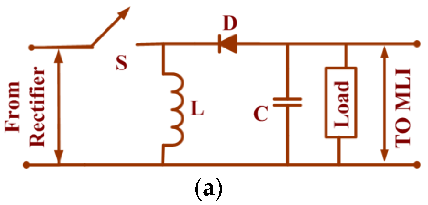
2.4. DC-DC Converter

The primary purpose of introducing a DC-DC converter, the front-end stage of the MLI is to regulate the voltages. The output from the PMSG is fluctuating and is not predictable. This increases the voltage stress across the inverter switches, which increases the size of the filters used in the circuit. Furthermore, power quality is affected. For prevent these effects, a DC-DC converter is introduced to regulate the voltage. Literature provides the usage of boost topology; in this paper, the boost is replaced by buck-boost and Cuk topologies. A Proportional Integral (PI) controller regulates the output voltage of the DC-DC converter.

2.4.1. Case (i) with a Buck-Boost Converter

A DC-DC buck-boost converter is used to convert the output DC voltage of the diode rectifier into the DC voltage of the desired magnitude. The closed-loop voltage control of this converter maintains the output voltage at the reference value. Figure 3a shows the circuit diagram of a buck-boost converter. There are two modes of operation of the converter.
In mode I, when the switch is in the ON condition, the inductor current increases from a minimum value Imin to a maximum value Imax, and the diode is in the OFF condition. In mode II, the switch is turned OFF; the diode is turned ON, providing a path for the inductor current and thereby decreasing the inductor current. Equations (17) and (18) respectively show the modeling of the buck-boost converter in mode I and II. Equation (19) gives the average output voltage of the buck-boost converter [13], which is the DClink voltage.
d i L d t = 1 L V s ,   d v c d t = 1 C R V D C
d i L d t = 1 L V D C ,   d v c d t = 1 C ( i L 1 R V D C )
V D C = V s δ 1 δ
where Vs is the average output voltage of the diode rectifier and δ is the duty ratio of the switch “S”. Equations (20) and (21) give the equations for the design of the converter [14]:
L = V s δ f Δ I
C = I o δ f Δ V o
where Io is the output current of the converter, f is the switching frequency, ΔI is the inductor ripple current, and ΔVo is the ripple voltage of the capacitor.

2.4.2. Case (ii) with the Cuk Converter

The Cuk converter has two modes of operation. The output voltage can be higher or lesser than the input voltage depending upon the value of duty ratio. The input current is continuous, which is not the case for a buck-boost converter. Figure 3b shows the circuit diagram of a Cuk converter. Equations (22) and (23) respectively show the modeling of a Cuk converter in mode I and II. Equation (24) gives the average output voltage of the Cuk converter.
{ d i L 1 d t   =   1 L 1 V s ,   d i L 2 d t   =   1 L 2 ( V c 1   +   V D C ) d v c 1 d t   =   1 C 1 i L 2 ,   d v c 2 d t   =   1 C 2 ( i L 2   +   1 R V D C )
{ d i L 1 d t   =   1 L 1 ( V s     V C 1 ) ,   d i L 2 d t   =   1 L 2 V D C d v c 1 d t   =   1 C 1 i L 1 ,   d v c 2 d t   =   1 C 2 ( i L 2   +   1 R V D C )
V D C = V s δ 1 δ
Equations (25)–(28) give the design equations for the circuit parameters [14]:
{ L 1 = δ V s f Δ I L 1 ,   L 2 = δ V s f Δ I L 2 C 1 = ( 1 δ ) I s f Δ V C 1 , C 2 = δ   V s 8 L 2 f 2 Δ V C 2
where Is is the input current (current from the diode rectifier), f is the switching frequency, ΔVc1 and ΔVc2 are the ripple voltages of the capacitors C1 and C2 respectively, and ΔIL1 and ΔIL2 are the ripple currents of the inductors L1 and L2 respectively. Figure 3a,b shows the buck-boost and Cuk converters, respectively. The values of the inductance and the capacitance are chosen to be higher than their critical values. The input voltage of the DC-DC converter varies as the PMSG output voltage varies because of the variation in the wind speed.

2.5. PI Controller

The voltage output of the DC-DC converter is kept at the desired voltage using a PI controller. The PI controller is widely used because it has only two parameters that need to be tuned. Besides this, its steady-state error is lower. The outputof the PI controller has two parts. The proportional partis proportional to the magnitude of the error e(t) or to the difference between the reference and the actual output. The integral part is proportional to the integral of the error [15]. The values of the PI controller gains are found using Zeigler’s second method of tuning. The steps for finding the parameters are:
  • The system is run by keeping the integral gain (I) as zero. The value of proportional gain (P) is increased from zero to a value Pcr(critical)from zero until a constant magnitude oscillation is produced.
  • This value of the P(Pcr) and the period of oscillation Tcr are calculated.
  • The gains of the controller are found using Equations (26)–(28):
P = 0.45 P c r
T i = T c r 1.2
I = P T i
The above steps yielded the P and I values 0.00045 and 0.0035, respectively.

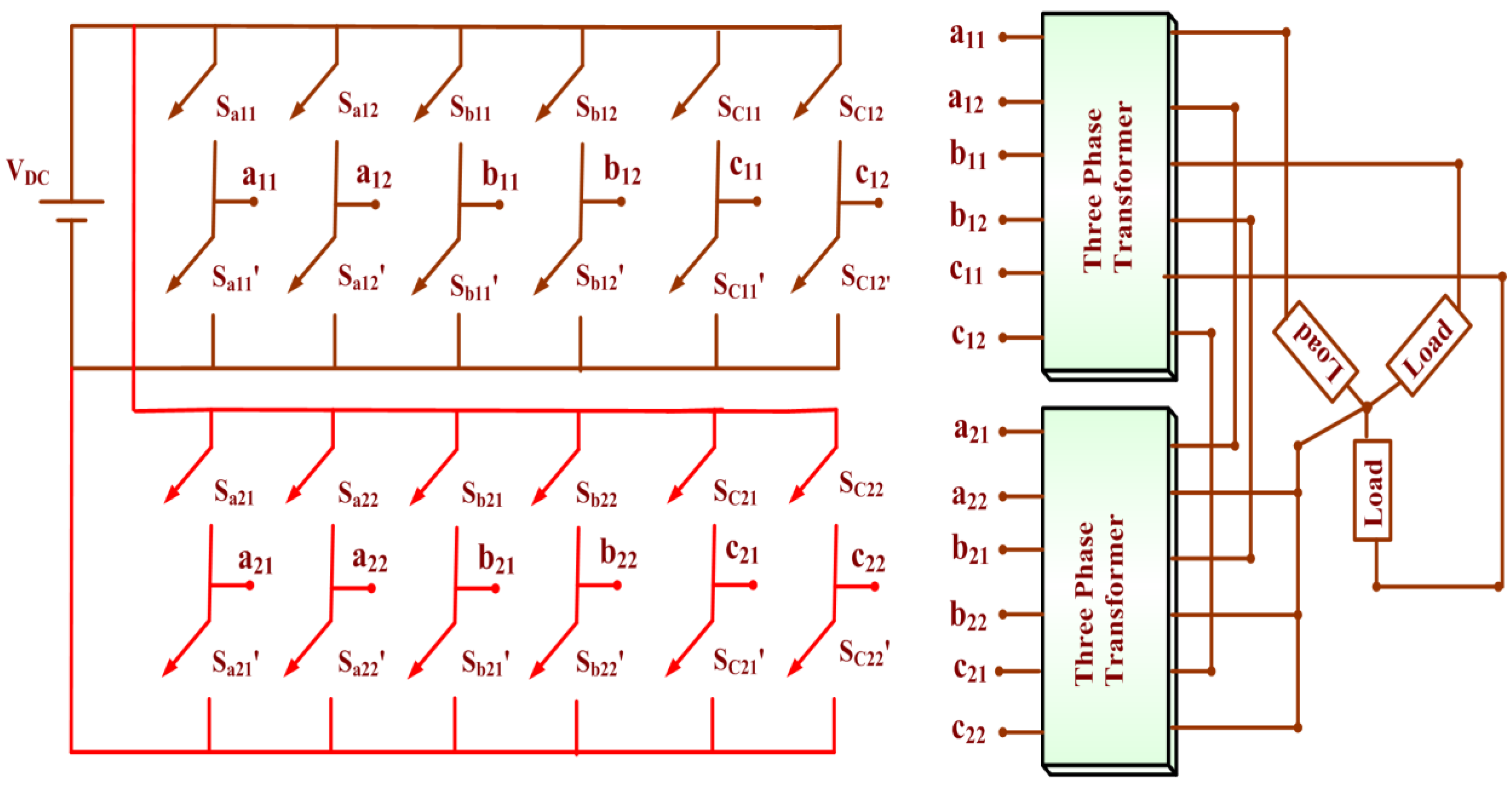
2.6. Five Level Converter

The output of the DC-DC converter is fed to the multilevel inverter (MLI). MLIs have more efficiency, a lower total harmonic distortion (THD), and lower switching stresses The Cascaded H Bridge (CHB) inverter has many advantages over diode-clamped and flying capacitor inverters; for example, it does not require clamping diodes and balancing capacitors, and it is easy to construct for higher levels. The CHB inverter requires a separate DC source for each bridge. The paper uses a new five-level inverter, which is the modified form of the CHB inverter, but it does not require a separate DC source. This inverter requires a single DC source irrespective of levels and phases, thus reducing the complexity and cost of the inverter. The inverter requires an (m − 1)/2 number of transformers, form the multilevel inverter [16,17,18,19,20,21,22,23,24,25,26,27,28,29,30,31,32,33,34,35,36,37,38] The inverter converts the DC voltage into a five-level AC voltage of the desired frequency (50 Hz). Figure 4 shows the proposed three-phase five-level inverter. There are many switching techniques available for MLI; selective harmonic elimination is crucial among them. In SHE, the harmonic equations are considered.

2.7. New Selective Harmonic Elimination

Selective harmonic elimination (SHE) providesan output voltage with fewer harmonics by adjusting the switching pattern. Transcendental equations describing the harmonics are solved in Newton-Raphson (N-R) to obtain two switching angles of a five-level inverter, as shown in Figure 5.
The five-level output is expressed in the Fourier series as:
v a ( ω t ) = n = 1 , 3 , 5 4 V D C n π ( cos θ 1 + cos θ 2 ) sin ( n ω t )
where θ1 and θ2 are the switching angles, and 0 < θ1 < θ2 < π/2. The fundamental voltage and its peak are given as
V 1 = 4 V D C π ( cos θ 1 + cos θ 2 ) V m 1 = 4 V D C π
The modulation index (MI) is given as M I = V 1 V m 1 .
Equation (30) is rewritten for the fundamental and third harmonic as Equations (31) and (32):
cos θ 1 + cos θ 2 = π V 1 4 V D C
cos ( 3 θ 1 ) + cos ( 3 θ 2 )   =   0
Equations (31) and (32) are solved by the Newton-Raphson method as follows:
  • Set initial values for θ 0 = [ θ 1 0 , θ 2 0 , θ 3 0 , , θ N 0 ] ;
  • Obtain the Fundamental and harmonic equations as { f 1 ( θ 1 , θ 2 , θ 3 , θ N ) = π 4 M i f 2 ( θ 1 , θ 2 , θ 3 , θ N ) = 0 f N ( θ 1 , θ 2 , θ 3 , θ N ) = 0 } ;
  • Obtain f ( θ 0 ) = f 0 ;
  • Linearize the function f 0 + [ f θ ] 0 Δ θ = 0 ;
  • Obtain the Jacobian matrix [ f θ ] 0 = [ f 1 θ 1 0 f 1 θ 2 0 f 1 θ N 0 f 2 θ 1 0 f 2 θ 2 0 f 2 θ N 0 f N θ 1 0 f N θ 2 0 f N θ N 0 ] ;
  • Obtain the new switching angle and repeat the procedure until the precise value is obtained;
  • θ n e w = θ o l d + Δ θ .
Solving (31) and (32) by the Newton-Raphson method, θ1 = 0.179 radians and θ2 = 0.87 radians. Hence, when these switching angles are used for triggering, the third harmonic is eliminated while other harmonics remain in the output.
A new SHE minimizes one more harmonic, e.g., the seventh harmonic, in addition to the fifth-order harmonic elimination. The seventh harmonic is minimised to a lower value, say 0.0001, as given by Equation (34):
cos ( 5 θ 1 ) + cos ( 5 θ 2 ) = 0
cos ( 7 θ 1 ) + cos ( 7 θ 2 ) = 0.0001
The switching angles are calculated by solving (33)and (34), and their values are θ1 = 0.09 rad and θ2 = 0.538 rad, thus reducing the THD still further. This technique considers the fifth and seventh harmonic equations to find the switching angles, while the fundamental equation is ignored [26]. The equations are solved using the Newton-Raphson method, which solves the transcendental equations using initial approximate values [27,28]. Figure 5d shows the output voltage of the five-level inverter with new SHE-PWM, and Figure 5e shows the THDs of the output voltage for the same load.
It is found from Figure 5c,e and Table 1 that the conventional five-level inverterhas a voltage THD of 20.92%, whereas the proposed new SHEPWM has a voltage THD of 17.48%. Hence, the new SHEPWM has a lower THD compared to the conventional SHEPWM.

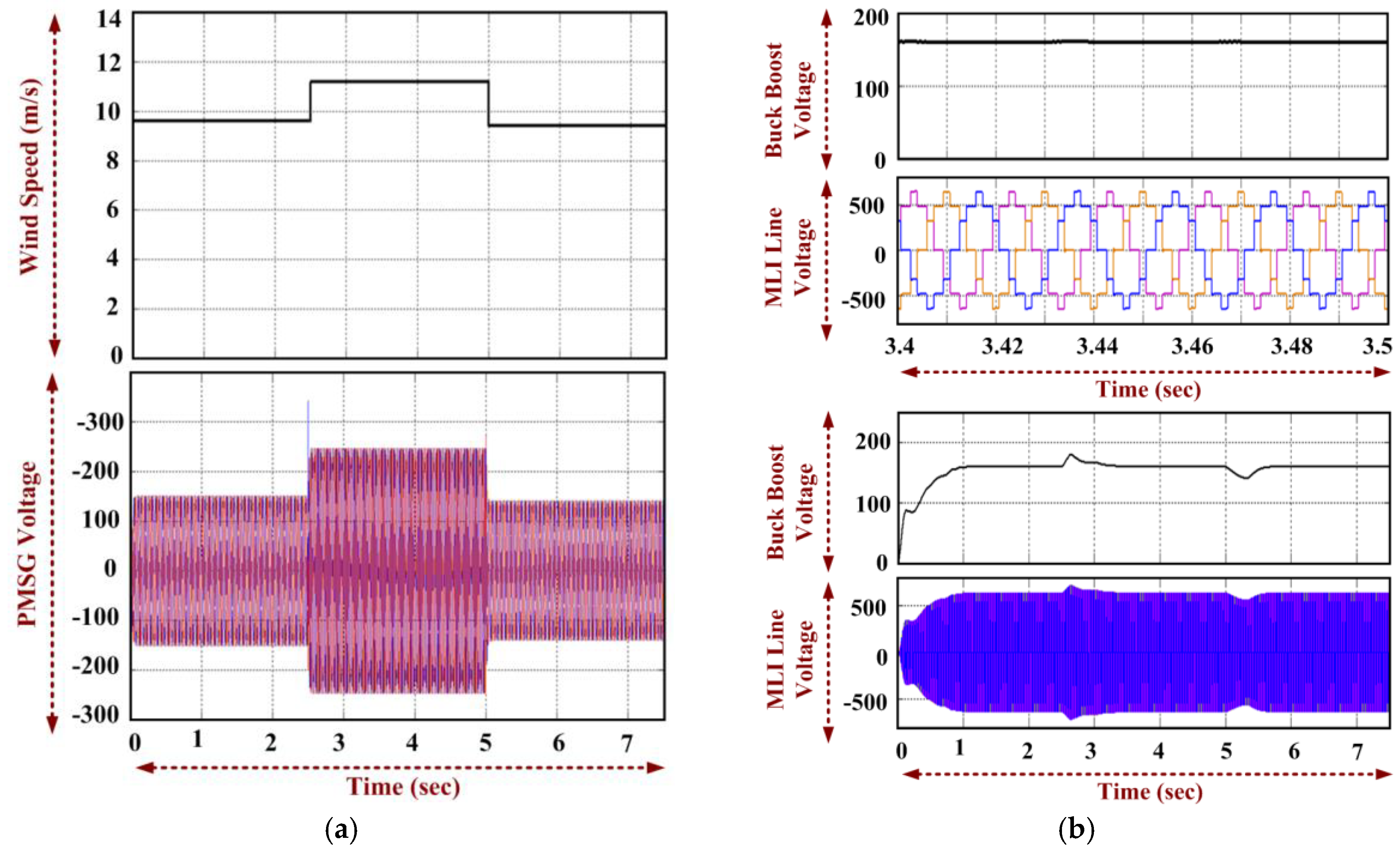
3. Simulation of the WES with DC-DC Converters and the Proposed CHB MLI

The system with PMSG, a diode rectifier, DC-DC converter, and five-level MLI is simulated in the MATLAB/ Simulink in closed loop for changing speeds of wind and with the RLload. The turbine rotor is coupled to the shaft of PMSG, whose output is fed to the diode rectifier. The voltage output of the diode rectifier is fed to the DC-DC converter whose output is connected to the proposed MLI, which is operated with the new SHEPWM. New SHEPWM reduces the harmonic and improves the power quality at the output [23,24].
The various parameters used in the simulation are given in the Appendix A. Figure 6 shows the simulated waveforms of the wind speed, PMSG voltage, DC-DC converter voltages, line voltage of the MLI, and load current. The speed of the wind varies from 9.6 m/s to 11.2 m/s at 2.5 s and from 11.2 m/s to 9.4 m/s at 5 s. Figure 6a shows the wind speed vs time graph and the PMSG voltage. The RMS PMSG voltages from 0–2.5, 2.5–5, and 5–7.5 seconds are around 100 V, 170 V, and 80 V, respectively.
Figure 6b shows the output voltage of the buck-boost converter, theline voltage, and its expanded scale with an RLload for MLI. The output voltage of the Cuk converter, the MLI line voltage, and its expanded scale are shown in Figure 6c. Figure 6d shows the load current for the RLload of 750 + j75.36 Ω/phase. Figure 7a,b shows the phase voltage of the MLI fed on the buck-boost and Cuk DC-DC converters and its expanded scale, respectively. Figure 7c shows the line voltage THD of the MLI.
Table 2 shows the time taken for the DClink voltages of the two converters to settle to the reference value with the change in the PMSG voltage.

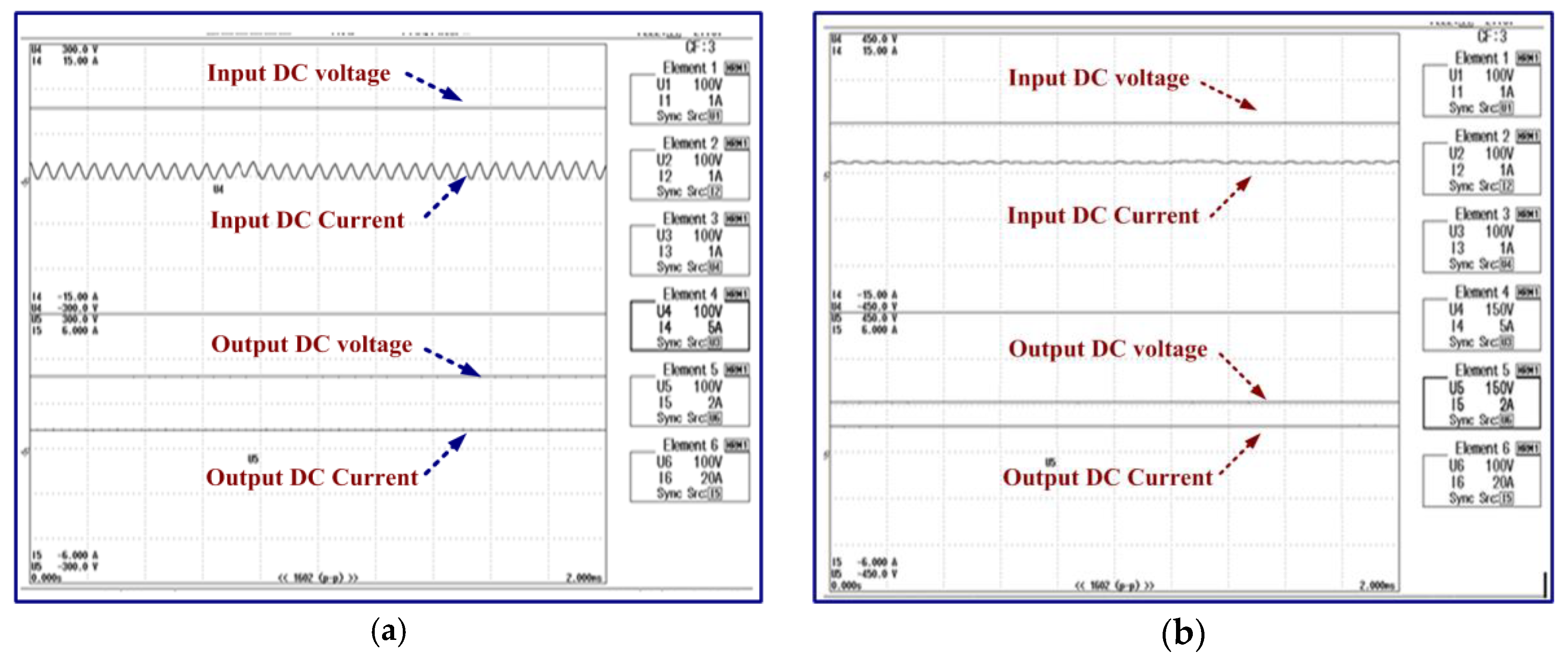
4. Hardware Implementation and Experimental Results

The three-phase diode rectifier, the two DC-DC converters, and the five-level inverter of the proposed topology are implemented in the hardware. The three-phase supply and a three-phase autotransformer mimic the variable speed operation of the turbine and the PMSG combination. The autotransformer feeds the three-phase diode rectifier, whose output is fed to the DC-DC converter (buck-boost or Cuk). The output from the DC-DC converter is given to the proposed five-level MLI, whose output is connected to a three-phase load through the isolating transformers. The switching device used for the MLI and DC-DC converters is CT60AM-18F. The field-programmable gate array (FPGA) produces switching signals (24 PWM signals) for the inverter, and the PI controller is implemented in a PIC microcontroller (PIC 4011). The PWM signals are given to the switches through the optocoupler and the driver circuits. Figure 8a shows the hardware implementation of the complete five-level MLI, and buck-boost converter. The hardware implementation of the system with the five-level MLI and Cuk converteris shown in Figure 8b. Table 3 describes the components used in the hardware.
The hardware setup of the system with the diode rectifier, five-level MLI, and DC-DC converters with an RL load of 750 + j75.36 Ω is tested for varying input AC voltages. The waveforms of the input AC voltage, DClink voltage, DClink current, MLI phase voltage, and load current are obtained for the AC input voltages of 60 V rms and 90 V rms. Figure 9a,b shows the input AC voltage, buck-boost converter voltage, DClink current, MLI phase voltage, and MLI/load current for the RL load for the AC input voltages of 60 V rms and 90 V rms, respectively. Figure 10a,b shows the input AC voltage, Cuk converter voltage, DClink current, MLI phase voltage, and MLI/load current for the RL load for the AC input voltages of 60 V rms and 90 V rms, respectively. The experimental line voltage THD of the MLI is shown in Figure 10c. The waveforms at 60 V rms and 90 V rms respectively are similar to the simulation waveforms shown in Figure 6 for the nearby rms value.
It can be seen from Figure 8 and Figure 9 that the DClink voltage of the system (with the two converters) is regulated at the desired level of 160 V even when the input voltage is changed.
Table 4 shows the comparison of the THDs of the line voltage. From Table 3, the line voltage THD from the simulation is 12.35%, and it is 12.16% from the hardware, which is 4% less than the THD obtained [23,24].
The efficiencies of the buck-boost and Cuk converters are measured for a resistive load connected at the output of the converters. Figure 10 shows the waveforms obtained for the buck-boost and Cuk converters, respectively. The waveforms of the input and output DC voltages and currents for the buck-boost converter are shown in Figure 11a. The waveforms of the input and output DC voltages and currents for the Cuk converter are shown in Figure 11b. Table 4 shows the readings obtained during the measurement of the efficiencies of the buck-boost and Cuk converters. From Table 5, it is noted that the efficiency of the Cuk converter is 93.12%,which is higher than that of the buck-boost converter, which has an efficiency of 82.05%.

5. Conclusions

A PMSG-based wind electric system with the buck-boost/Cukconverter and the proposed five-level MLI are considered. As the wind speed changes, the PMSG voltage and frequency changes, but for practical applications, these changes should not be allowed. Hence, a voltage controller is used that maintains the output voltage of the DC converter; hence, a constant AC output is obtained. A PI controller is deployed to regulate the output voltage of the buck-boost/Cuk converter. The time period of the operation of the inverter switches is set in such a way that the output frequency does not change. The MLI is controlled using a new SHE technique which reduces the THD. This SHE eliminates more harmonic content from the output also when compared to the conventional SHE. The whole system is simulated in a closed-loop for variable wind speeds with the RLload. The simulated waveforms of the wind speed, PMSG voltage, DClink voltage, voltages of MLI, and load current are obtained for the increasing and decreasing wind speeds for the RLload. The system with the buck-boost and Cuk converters is implemented in hardware with a three-phase AC and three-phase autotransformer, which mimic the variable speed wind turbine and PMSG combination. The system is experimentally tested with an RLload for varying AC input voltages.
The waveforms of the AC input voltage, DClink voltage (buck-boost/Cukconverter voltage), MLI phase, line voltages, and load currents are obtained for variable input voltages for both the converters. From the simulated and hardware results, it can be seen that the buck-boost and Cuk converters can control the voltage for the increasing and decreasing PMSG voltages, which is evident from the simulated and the experimental results. This reduces the stress level in the MLI. The efficiency of the Cuk converter is higher than that of the buck-boost converter. Hence, the proposed Cuk converter-based PMSG drive with the new SHE technique for MLI focuses on reducing the filter size andnumber of DC sources for MLI and reduces the THD.

Author Contributions

Conceptualization, P.T. and D.K.; methodology, U.S., M.S.B., S.P.; software, P.T.; validation, T.D., U.S., S.P. and M.M.; formal analysis, P.T., M.S.B.; investigation, P.T., D.K.; resources, S.P.; data curation, Z.L.; writing—original draft preparation, P.T., Z.L., M.M.; writing—review and editing, M.S.B., S.P.; visualization, Z.L., M.M.; supervision, D.K., Z.L., M.M.; project administration, S.P.; funding acquisition, Z.L., M.M. All authors have read and agreed to the published version of the manuscript.

Funding

This research received no external funding.

Acknowledgments

Authors would like to acknowledge the Renewable Energy Lab, Prince Sultan University, Saudi Arabia and Department of Energy Technology, Aalborg University, Esbjerg, Denmark for providing technical support and transfer of insight guidance for this research work.

Conflicts of Interest

The authors declare no conflict of interest.

Nomenclature

PTPower captured by the turbine
ASwept area of the rotor blades
ΡDensity of air
vwvelocity of wind
Cp sCo-efficient of power
PairTotal power in the wind
γPitch angle
RRadius of the turbine rotor
ωwRotor speed
fFrequency of voltage induced
NphPer phase number of turns
φpFlux per pole
Kw1Winding factor of the fundamental harmonic component
D and lDiameter and length of the stator core
PNumber of pole pairs
IaPhase current
XsSynchronous reactance
PemElectrical output power
PmMechanical input power
PcuCopper loss of stator
ProtRotational losses
PcoreCore losses of the machine
ωeElectrical speed
ψd, and ψqd and q-axes flux linkages
vds, and vqsStator d and q axes voltages in the synchronously rotating reference frame
ids, and iqsd and q axes stator currents in the synchronously rotating reference frame
Ld, and Lqd and q-axes inductances
ψmPermanent magnet flux linkage
pNumber of pairs of the pole
ωmMechanical speed of the rotor
VsAverage output voltage of the diode rectifier
VmPeak value of the phase voltage of the PMSG
FSwitching frequency
ΔIInductor ripple current
ΔVoRipple voltage of the capacitor
IsInput current (current from diode rectifier)
ΔVc1 and ΔVc2Ripple voltages of the capacitors C1 and C2
ΔIL1 and ΔIL2Ripple currents of the inductors L1 and L2
TcrThe period of the oscillation
θ1 and θ2Switching angles

Appendix A

Simulation ParameterValue
Buck-boost converterL, C50 mH, 330 μF
Switching frequency, duty cycle range18 kHz, 10–90%
Cuk converterL1, L2, C1, C250 mH, 1500 μH, 330 μF, 660 μF
Switching frequency, duty cycle range18 kHz, 10–90%
Transformer ratingskVA rating, turns ratio, voltage rating, current rating, frequency0.5 kVA, 1:1, 230 V/230 V, 2 A/2 A, 50 Hz
PI controllerkp, ki0.00045, 0.0035
Time delay for PI action, sampling time5 ms, 0.05 s
Load parametersRLloads750 + j75.36 Ω

References

  1. Sartika, L.; Rosyadi, M.; Umemura, A.; Takahashi, R.; Tamura, J. Stabilization of PMSG based Wind Turbine under Network Disturbance by using New Buck Controller System for DC-Link Protection. In Proceedings of the 5th IET International Conference on Renewable Power Generation, IET Digital Library, London, UK, 21–23 September 2016; pp. 1–6. [Google Scholar]
  2. Barote, L. Modeling and Operational Testing of an Isolated Variable Speed PMSG Wind Turbine with Battery Energy Storage. Adv. Electr. Comput. Eng. 2012, 12, 81–88. [Google Scholar] [CrossRef]
  3. Kumar, V.; Joshi, R.R.; Bansal, R.C. Optimal Control of Matrix-Converter-Based WECS for Performance Enhancement and Efficiency Optimization. IEEE Trans. Energy Convers. 2009, 24, 264–273. [Google Scholar] [CrossRef]
  4. Rodriguez, J.; Jih-Sheng, L.; Fang, Z.P. Multilevel inverters: A survey of topologies, controls, and applications. IEEE Trans. Ind. Electron. 2002, 49, 724–738. [Google Scholar] [CrossRef] [Green Version]
  5. Rodriguez, J.; Bernet, S.; Pontt, J.O.; Kouro, S. Multilevel Voltage-Source-Converter Topologies for Industrial Medium-Voltage Drives. IEEE Trans. Ind. Electron. 2007, 54, 2930–2945. [Google Scholar] [CrossRef]
  6. Zambra, D.A.B.; Rech, C.; Pinheiro, J.R. Comparison of Neutral-Point-Clamped, Symmetrical, and Hybrid Asymmetrical Multilevel Inverters. IEEE Trans. Ind. Electron. 2010, 57, 2297–2306. [Google Scholar] [CrossRef]
  7. Tudorache, T. Optimal Design Solutions for Permanent Magnet Synchronous Machines. Adv. Electr. Comput. Eng. 2011, 11, 77–82. [Google Scholar] [CrossRef]
  8. Ozcira, S.; Bekiroglu, N.; Oner, Y. Dynamic Analysis of Permanent Magnet Synchronous Generator with Power Electronics. Adv. Electr. Comput. Eng. 2010, 10, 11–15. [Google Scholar]
  9. Samuel, P.; Chandrashekhar, N.; Gupta, R. Wind energy conversion based on seven-level cascaded H-bridge inverter using LabVIEW FPGA. In Proceedings of the International Conference on Power, Control and Embedded Systems, Allahabad, India, 29 November–1 Decmber 2010; pp. 1–6. [Google Scholar]
  10. Boldea, I. The Electric Generator Hand Book Synchronous Generators; CRC Press, Taylor & Francis Group: New York, NY, USA, 2005. [Google Scholar]
  11. Porselvi, T.; Muthu, R. The PMSG based Wind Energy Conversion System with CUK Converter and CHB MLI with a Single DC Input. Int. Energy J. 2014, 14, 43–56. [Google Scholar]
  12. Sebastian, T.; Slemon, G.R. Transient modeling and performance of variable-speed permanent-magnet motors. IEEE Trans. Ind. Appl. 1989, 25, 101–106. [Google Scholar] [CrossRef]
  13. Porselvi, T.; Muthu, R. Seven level three phase Cascaded H-Bridge inverter with single DC source. ARPN J. Eng. Appl. Sci. 2012, 7, 1546–1554. [Google Scholar]
  14. Rashid, M.H. Power Electronics: Circuits, Devices, and Applications; Dorling Kindersley (India) Private Limited: Noida, India, 2007. [Google Scholar]
  15. Williums, B.W. Power Electronics: Devices, Drivers, Applications and Passive Components, 2nd ed.; McGraw Hill Higher Education: Burr Ridge, IL, USA, 1992. [Google Scholar]
  16. Basilio, J.C.; Matos, S.R. Design of PI and PID controllers with transient performance specification. IEEE Trans. Educ. 2002, 45, 364–370. [Google Scholar] [CrossRef]
  17. Urmila, B.; Subbarayudu, D. Multilevel Inverters-A Comparative Study of Pulse Width Modulation Techniques. Int. J. Sci. Eng. Res. 2010, 1, 5–11. [Google Scholar]
  18. Peng, F.Z.; McKeever, J.W.; Adams, D.J. Cascade multilevel inverters for utility applications. In Proceedings of the 23rd International Conference on Industrial Electronics, Control, and Instrumentation, New Orleans, LA, USA, 14 November 1997; pp. 437–442. [Google Scholar]
  19. Porselvi, T.; Muthu, R. Modeling and Control of the PMSG for the Wind Energy Conversion System with the CHB Inverter with the New Selective Harmonic Elimination Technique. Int. Rev. Model. Simul. IREMOS 2013, 6, 767–773. [Google Scholar]
  20. Jain, A.; Shankar, S.; Vanitha, V. Power Generation Using Permanent Magnet Synchronous Generator (PMSG) Based Variable Speed Wind Energy Conversion System (WECS): An Overview. J. Green Eng. 2017, 7, 477–504. [Google Scholar] [CrossRef] [Green Version]
  21. Smith, C.J.; Crabtree, C.J.; Matthews, P.C. Impact of wind conditions on thermal loading of PMSG wind turbine power converters. In Proceedings of the 8th IET International Conference on Power Electronics, Machines and Drives (PEMD-2016), Glasgow, UK, 19–21 April 2016; Volume 10, pp. 1–6. [Google Scholar]
  22. Carrara, G.; Gardella, S.; Marchesoni, S.; Sciutto, G. A new multilevel PWM method: A theoretical analysis. IEEE Trans. Power Electron. 1992, 7, 497–505. [Google Scholar] [CrossRef]
  23. Porselvi, T.; Deepa, K.; Muthu, R. FPGA Based Selective Harmonic Elimination Technique for Multilevel Inverter. Int. J. Power Electron. Drive Syst. 2018, 9, 166–173. [Google Scholar] [CrossRef]
  24. Prathiba, T.; Renuga, P. A comparative study of Total Harmonic Distortion in Multi level inverter topologies. J. Inf. Eng. Appl. 2012, 2, 26–36. [Google Scholar]
  25. Porselvi, T.; Deepa, K.; Muthu, R. Hardware Implementation of Three Phase Five-level Inverter with Reduced Number of Switches for PV Based Supply. J. Green Eng. 2017, 7, 527–546. [Google Scholar] [CrossRef] [Green Version]
  26. Rolan, A.; Luna, A.; Vazquez, G.; Aguilar, D.; Azevedo, G. Modeling of a variable speed wind turbine with a Permanent Magnet Synchronous Generator. In Proceedings of the IEEE International Symposium on Industrial Electronics, Seoul, Korea, 5–8 July 2009; pp. 734–739. [Google Scholar]
  27. Jih-Sheng, L.; Fang, Z.P. Multilevel converters-a new breed of power converters. IEEE Trans. Ind. Appl. 1996, 32, 509–517. [Google Scholar] [CrossRef]
  28. Deepa, K.; Savitha, P.; Vinodhini, B. Harmonic analysis of a modified cascaded multilevel inverter. In Proceedings of the1st International Conference on Electrical Energy Systems, Newport Beach, CA, USA; 2011; pp. 92–97. [Google Scholar]
  29. Woodford, C.; Phillips, C. Numerical Methods with Worked Examples, 1st ed.; Chapman and Hall: London, UK, 1997; pp. 45–57. [Google Scholar]
  30. Athira, S.; Deepa, K. Modified Bidirectional Converter with Current Fed Inverter. Int. J. Power Electron. Drive Syst. 2015, 6, 387–395. [Google Scholar]
  31. Savitha, K.P.; Kanakasabapathy, P. Multi-port DC-DC converter for DC microgrid applications. In Proceedings of the IEEE 6th International Conference on Power Systems, New Delhi, India, 28–29 November 2016; pp. 1–6. [Google Scholar]
  32. Nair, P.; Deepa, K. Two-port DC-DC converter with flyback inverter for rural lighting applications. In Proceedings of the 2015 International Conference on Technological Advancements in Power and Energy (TAP Energy), Kollam, India, 24–26 June 2015; pp. 249–253. [Google Scholar]
  33. Vijayakumari, A.; Anusha, K.V. Subharmonics detection in regular sampled Space Vector PWM and its mitigation with low computational dynamic sampling. In Proceedings of the IEEE International Conference on Power Electronics, Drives and Energy Systems, PEDES, Trivandrum, India, 14–17 December 2016; pp. 1–6. [Google Scholar]
  34. Sandhu, M.; Thakur, T. Reduction of Harmonics In a Hybrid PV/Wind Microgrid Using a Modified Multilevel Inverter. In Proceedings of the 2019 IEEE Electrical Power and Energy Conference (EPEC), Montreal, QC, Canada, 16–18 October 2019; pp. 1–6. [Google Scholar]
  35. Jayabalan, M.; Jeevarathinam, B.; Sandirasegarane, T. Reduced switch count pulse width modulated multilevel inverter. IET Power Electron. 2017, 10, 10–17. [Google Scholar] [CrossRef]
  36. Zerouali, M.; Boutouba, M.; Ougli, A.E.; Tidhaf, B. Control of variable speed wind energy conversion systems by fuzzy logic and conventional P&O. In Proceedings of the 2019 International Conference on Intelligent Systems and Advanced Computing Sciences (ISACS), Taza, Morocco, 26–27 December 2019; pp. 1–5. [Google Scholar]
  37. Soliman, M.A.; Hasanien, H.M.; Al-Durra, A. High-Performance Frequency Converter Controlled Variable-Speed Wind Generator Using Linear-Quadratic Regulator Controller. In Proceedings of the 2019 IEEE Industry Applications Society Annual Meeting, ‎Piscataway, NJ, USA, 29 September–3 October 2019; pp. 1–7. [Google Scholar]
  38. Shrivastava, S.; Tripathi, A.; Verma, K.S. Reduction in total harmonic distortion by implementing multi-level inverter technology in grid integrated DFIG. In Proceedings of the 2015 Communication, Control and Intelligent Systems (CCIS), Mathura, India, 7–8 November 2015; pp. 491–495. [Google Scholar]
Figure 1. Diagram of a wind-electric system (WES) with a diode rectifier, DC-DC converter, and multilevel inverter (MLI).
Electronics 09 00979 g001
Figure 2. Cp vs. tip speed ratio (TSR) curve.
Electronics 09 00979 g002
Figure 3. The power circuit of (a) the buck-boost converter and (b) Cuk converter.
Electronics 09 00979 g003aElectronics 09 00979 g003b
Figure 4. Circuit diagram of the three-phase five-level Cascaded H Bridge (CHB)-MLI with a single DC source.
Electronics 09 00979 g004
Figure 5. (a) The 5-level output (half wave). (b) Output phase voltage for the conventional five-level inverter. (c) Total harmonic distortion (THD) of the output phase voltage for the conventional five-level inverter. (d) Output phase voltage for the five-level inverter with new Selected Harmonic Elimination (SHE) Pulse Width Modulation (PWM). (e) The output voltage of the single-phase five-level inverter with new SHE PWM.
Electronics 09 00979 g005aElectronics 09 00979 g005b
Figure 6. Simulation results: (a) wind speed vs time and Permanent Magent Synchronous Generator (PMSG) voltage for the increase in wind speed at 2.5 s and decrease in wind speed at 5 s; (b) converter voltage, MLI line voltage, and its expanded scale with an RLload for the buck-boost converter; (c) converter voltage, MLI line voltage, and its expanded scale with an RLload for the Cuk converter; (d) load current in the expanded scale with the buck-boost converter (top) and Cukconverter (bottom).
Electronics 09 00979 g006aElectronics 09 00979 g006b
Figure 7. Phase voltage and its expanded waveform of the MLI with the RLload for (a) the buck-boost converter, (b) the Cuk converter, and (c) the line voltage THD.
Electronics 09 00979 g007
Figure 8. Experimental setup of the five-level MLI with the (a) buck-boost converter and (b) Cuk converter.
Electronics 09 00979 g008
Figure 9. Experimental results: (a) input AC voltage, buck-boost voltage, DClink current, MLI phase voltage, and MLI/load current for the AC input voltage of 60 V; (b) input AC voltage, buck-boost voltage, DClink current, MLI phase voltage, and MLI/load current for the AC input voltage of 90 V.
Electronics 09 00979 g009
Figure 10. Experimental results: (a) input AC voltage, Cuk converter voltage, DClink current, MLI phase voltage, and MLI/load current for the AC input voltage of 60 V; (b) input AC voltage, Cuk converter voltage, DClink current, MLI phase voltage, and MLI/load current for the AC input voltage of 90 V; (c) line voltage THD.
Electronics 09 00979 g010
Figure 11. Input and output DC voltages and currents of (a) the buck-boost and (b) Cuk converters for efficiency measurements.
Electronics 09 00979 g011
Table 1. Comparison of the voltage THD for the conventional five-level inverter and the new SHEPWM with the RLload.
Voltage THD
Conventional five-level inverter20.92%
Proposed five-level inverter with New SHEPWM17.48%
Table 2. Settling times for the DClink voltage of the two converters with the change in PMSG voltage.
ConverterTime to Settle with an Increase in PMSG VoltageTime to Settle with the Decrease in PMSG Voltage
Buck-boost 0.9 s0.8 s
Cuk0.9 s1 s
Table 3. Details of the components used in the hardware.
Hardware ItemsSpecifications
Switching devicesCT60AM-18F
MicrocontrollerPIC 4011 (dsPIC00F4011)
FPGASpartan 3E
Opto-coupler6N137
Gate driverIR2110
TransformersToroidal core, turns ratio: 1:1, 230 V, 2 A, 50 Hz
Buck-boostL = 50 mH, C = 330 μF
CukL1 = 50 mH, L2 = 1500 μH, C1 = 330 μF, C2 = 660 μF
Load750 Ω, 240 mH
ControllerP = 0.00045, I = 0.0035
Table 4. Comparison of theline voltage THDs.
Line Voltage THD%
Simulation12.35
Experimental12.116
Table 5. Of theline voltage THDs.
ConverterInput DC Voltage (VDCI) (V)Input DC Current (IDCI) (A)Output DC Voltage (VDCO) (V)Output DC Current (IDCO) (A)Efficiency
Buck-boost159.611.102160.360.982.05%
Cuk converter161.631.203160.41.128993.12%

