A VOHE System for Underwater Communications


1
Department of Science and Technology, Hirosaki University, 3-Bunkyocho, Hirosaki, Aomori 036-8560, Japan
2
GBase, Tianjin High-Tech District, Tianjin 300384, China
*
Author to whom correspondence should be addressed.
Electronics 2020, 9(10), 1557; https://doi.org/10.3390/electronics9101557
Submission received: 27 August 2020
/
Revised: 18 September 2020
/
Accepted: 19 September 2020
/
Published: 23 September 2020
(This article belongs to the Special Issue Underwater Communication and Networking Systems)
Abstract
:This paper presents a new method for encrypting holographic information based on optical and acoustic signals called a Virtual Optical Holographic Encryption (VOHE) system for underwater communications that can be applicable for communications between deep submergence research vehicles. The transmission medium is composed of a combination of optical signals and acoustic signals together to form the VOHE system for transmitting system information. The optical encryption system provides essential parameters for constructing secure communications such as the propagation wavelength (λ) and focal length (f) of the Fourier lens, which are considered as keys for implementing encryption and decryption processes. An expanded RSA (ERSA) algorithm using a complex function sends system information (λ, f) as a message to a receiver. To determine accuracy of the information retrieved by the proposed technique, the minimum mean square error (MSE) was conducted to evaluate the accuracy of the received signal. The VOHE system employs virtual optical encryption system was simulated based on COMSOL Multiphysics simulation software. Finally, the National Institute of Standards and Technology (NIST) method and Pollard’s rho method were separately applied to evaluate the proposed ERSA algorithm. Obtained results showed that ERSA is able to achieve a more significant security level than RSA.
1. Introduction
Underwater optical encryption has drawn great attention from researchers in the field of enhancing information security due to its remarkable advantages for rapidly and securely managing information processing [1,2,3,4]. A paper by Yu C et al. proposed a novel image encryption scheme, in which the positions of the values of image pixels were scrambled to confuse the relationship between the cipher text and the original image [5]. A new encryption technique has also been introduced by Hennelly [6] using juxtaposition of sections of the image in fractional Fourier domains. Virtual optical encryption for holographic is a common kind of a new and a developing technology. It can handle very large computational domains which are able to increase sensitivity and reduce the signal to noise ratio (SNR) [7,8].
The virtual optical holographic encryption (VOHE) system has been widely used in recent years compared with other cryptographic systems for achieving preferable security [9,10]. In summary, the VOHE system has many advantages and the optical system can not only adopt a method of building an optical light path, but also uses an encryption method as a means of providing high-end secure systems [11,12,13].
Rivest, Shamir, and Adleman introduced the RSA (Rivest–Shamir–Adleman) public key encryption system in 1978 [14]. In addition to the standard RSA scheme, researchers have also devoted their studies to designing a system based on an RSA-based method with further efficiency and security considerations, such as the CRT-RSA scheme [15], the Prime Power RSA scheme [16], and the Kuwakado–Koyama–Tsuruoka RSA-type scheme of singular cubic curve [17]. In 2002, Elkamchouchi et al. extended the RSA using Gaussian integers [18], which was similar to the method of Kuwakado, Koyama and Tsuruoka. Castagnos [19] proposed a probabilistic scheme based on RSA modulus in 2007, which also included the same modulus equations as the above two schemes [17,18].
This paper employs a VOHE system for underwater communications to encrypt information based on an extension of RSA (ERSA) algorithm using complex functions. This paper is organized as follows: in Section 2, the encryption scheme, decryption scheme and ERSA algorithm are briefly introduced. The complexity of the method based on Pollard’s rho method is also given in this section. Section 3 contains the results based on computer simulations for the encryption and decryption process and the ERSA public key process. In Section 4, the mean square error (MSE) is calculated between the original code and retrieved code; the National Institute of Standards and Technology (NIST) method tool is applied to evaluate the security of the proposed ERSA algorithm. Finally, the conclusions of the study are summarized in Section 5.
2. The VOHE System Design
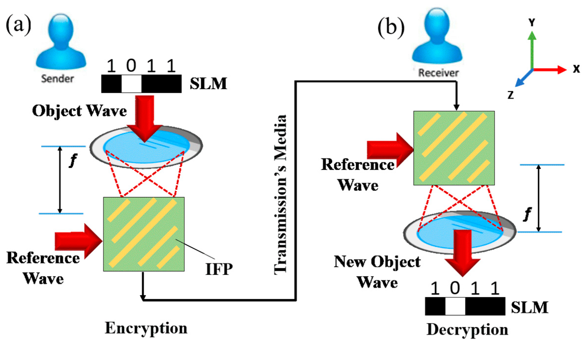
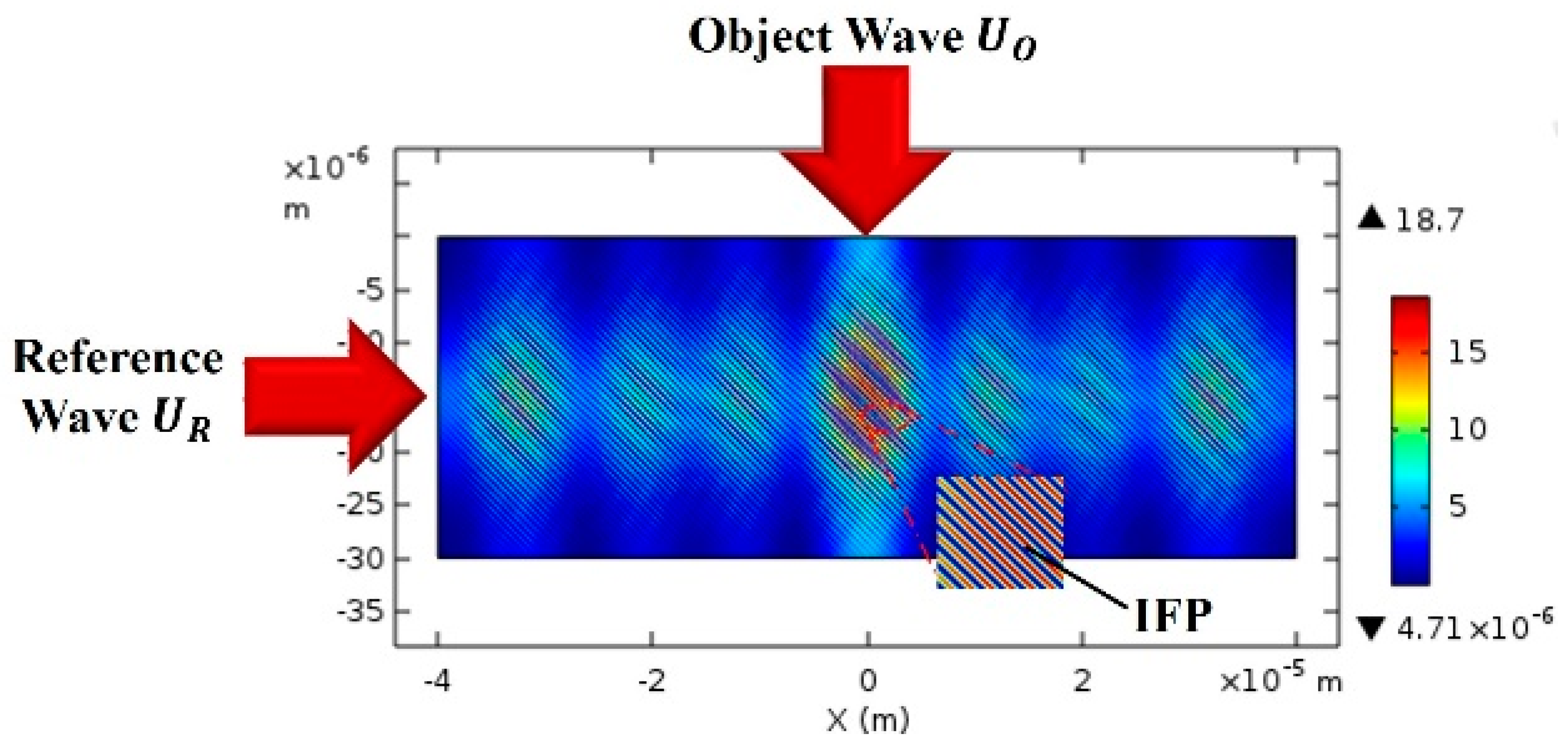
The system model of the optical encryption holographic [20], as shown in Figure 1, includes the following components: a space light modulator (SLM), a Fourier lens with a focal length f, an object wave which carries object information (e.g., 1011) and a reference wave. The transmission’s media such as optical signals combined with acoustic signals are implemented as a means to an send interference fringe pattern (IFP), as shown Figure 1, that carries object information to a receiver [21]. The optical signal is used to encrypt the object information, and the encrypted signal is carried by an acoustic signal, and then the signal will be transmitted to the acoustic channel for long-distance transmission.
When the complex amplitude of the reference wave and object wave at plane z = 0, then is given by [22]:
where, is the real amplitude of the reference wave; is the waist radius of the reference wave; is the wave number for a reference, is the reference wavelength, and n is the index of refraction of holographic material, is the wave front curvature of the reference wave at distance x from the focal plane position and is defined by
Here, is the Rayleigh range.
In Figure 1a, firstly, the light will pass through the SLM to carry object information e.g., 4 bits “1011”, and the output will be the object wave. Secondly, the object wave passes through the Fourier lens with a focal length f. In Fourier optics, the process of the object wave that is focused by the Fourier lens is called a Fourier transformation. Hence, the output from Fourier lens is , which is focused on holographic plane and is calculated by [23]:
where, is the object wavelength, f is the focal length, is object information e.g., “1011”, u represents the spatial coordinates in the Fourier/image space and is the spatial frequency.
2.1. Holographic Encryption
The Figure 1a shows the encryption process of the object information where the object wave flows across the reference wave to generate a cipher that carries object information. This cipher is called a complex interference fringe pattern (IFP) [24,25]. The electric field intensity of the IFP is calculated by:
2.2. Holographic Decryption
The decryption process is the inverse of the above encryption process. In the Figure 1b, the IFP is modulated and illuminated only by the reference wave to produces an image of new object wave which is given by:
The MOD is a holographic refractive index modulator function, which modulates holographic material refractive index above a certain threshold value of electric field intensity [26]. Where, MOD =, dn is the modulation coefficient, the max operator calculates the maximum value within (x, y) domains, and TH is an exposure threshold.
To obtain the retrieved original image that is carried by the Fourier transformation in the Fresnel approximation is applied as
where, FT represents Fourier transformation.
In the encryption and decryption processes, the reference wave should match and coordinate well with these two processes to achieve the best outcome [27]. Hence, the wavelength of the reference wave is considered as the first key. We would like to point out here that the output signal from the Fourier lens is considered as another new cipher. Therefore, the focal length f is regarded as a second key.
2.3. ERSA (Expanded RSA) Algorithm
To achieve a resilient security of data transmission as both a sender and a receiver, this study implemented an expanded encryption process based on the expansion of the RSA algorithm, which was done by using complex function.
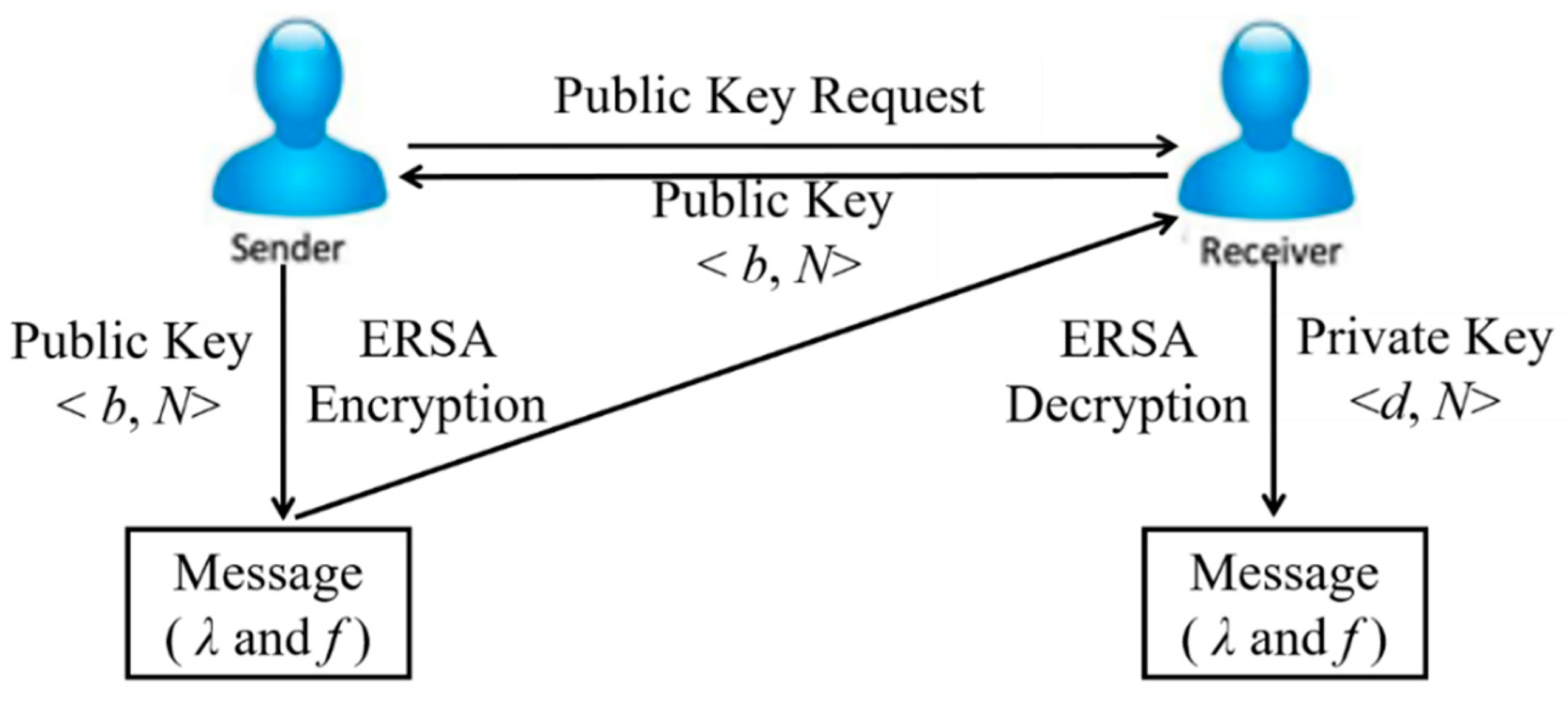
As wavelength λ and focal length f are concerned in the encryption and decryption systems, the wavelength λ and focal length f had to be transmitted to the receiver using a secure channel. The ERSA algorithm was implemented to send system information (λ, f) as a message to the receiver, as shown in Figure 2. The operation was as follows, firstly, a sender sends a request to a receiver for the receiver’s public key (b, N). Then, the receiver sends its public key to the sender. The sender will encrypt the message (λ, f) using the receiver’s public key and send the encrypted message to the receiver. When the receiver receives the cipher, it decrypts it using its private key (d, N) to get the message (λ, f).
The public and private keys’ generation of the ERSA algorithm is done using the following steps:
- Multiply the p and q values to produce , where N is also a complex number. In the ERSA algorithm, the extended Euler function is and, for the conventional RSA algorithm, the Euler function is . Hence, compared to the RSA Euler-phi function, the ERSA provides more security for extending Euler-phi functions than that of the conventional RSA. In contrast to the RSA algorithm, the ERSA includes negative integers by which security can be strengthened.
- A private key (d, N) and a public key (b, N) are calculated as shown in Algorithm 1. The encryption and decryption processes are shown in Algorithms 2 and 3, respectively. The message m that includes information about λ, f must be sent to the receiver through a secure channel. As shown in Algorithm 2, the cipher c, which is formed in a complex function, is sent to the receiver. At the receiver side, the receiver is using its private key to calculate the message m1, which is also a complex number, as shown in Algorithm 3. Finally, the process to convert m1 from a complex number to a real number m that contains information about λ, f is given in Algorithm 4.
Algorithm 1 Calculate <Keys> Input: 1: N 2: 3: 4: Output
| Algorithm 2 <Encryption> |
| Input: |
| 1: |
| 2: Output: |
| Algorithm3 <Decryption> |
| Input: |
| 1: m1 |
| 2: |
| 3: Output |
| Algorithm 4 <V2M (m1, N)> |
| Input: , |
| 1: |
| Input: , |
| 2: |
| 3: |
| 4: : |
| 5: : |
| 6: : |
| 7: : |
| 8: |
| 9: Output m |
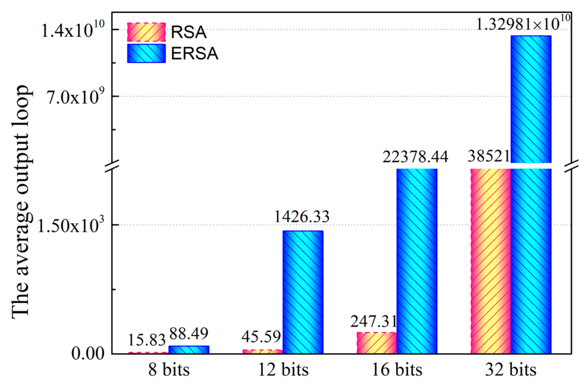
The security of the ERSA algorithm depends upon the intractability of the prime factorization problem. This method is an expanded Pollard’s rho algorithm for prime factorization to analyze the security of ERSA [30]. ERSA’s public key consists of the modulus N and b, however, modulus N comprises a product of two complex numbers, as shown in Table 1. We would like to mention here that the parameter of modulus N is very important for strengthening the complexity of the public key from trap door attacks. In Table 1, we compare the modulus N and key size of ERSA and RSA.
To verify the security of the modulus N, modulus N is analyzed using Pollard’s rho method. This method calculates average output loops using the same key length for both RSA and ERSA; if the is higher than the modulus N, then better security can be achieved.
As shown in Figure 3, Pollard’s rho method is used to compute of modulus N for 8 bits, 12 bits, 16 bits and 32 bits. Under the average output loop of Pollard’s rho method, the ERSA algorithm is more secure than the RSA algorithm when both have the same key size. Therefore, in this study, using the ERSA algorithm to encrypt system information (λ, f) is a more appropriate method for strengthening the security of the data transmissions.
3. Experiment Results and Analysis
Simulation was conducted using the COMSOL Multiphysics tool to simulate the process of the encryption and decryption [31]. As a numerical example, the parameters of the simulation were the object wavelength of = 632.8 nm, the reference wavelength of = 632.8 nm, the hologram material index n = 1.3 and a Fourier lens of focal length of f = 4.20 mm. A rectangle size of a hologram domain was selected where the horizontal size was Lx = 80 μm and the vertical size was Ly = 30 μm.
3.1. Encryption Process
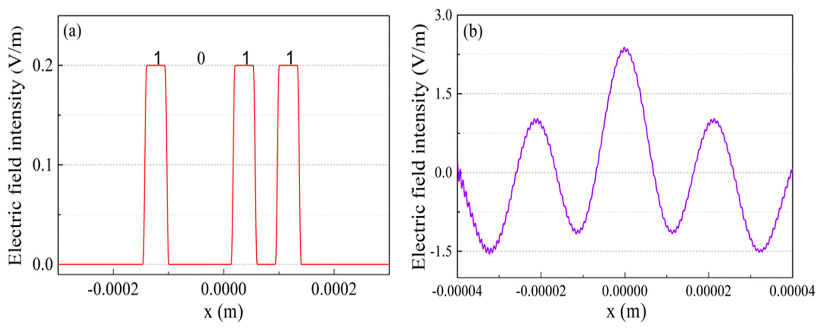
In Figure 4a, we supposed that a 4-bit block object message which was required to be sent from sender to receiver e.g., “1011”. This object message was carried by object wave . As the object wave passed through the Fourier lens with focal length of f = 4.20 mm, the output from the Fourier lens was an electric field of amplitude that was focused on holographic plane, as shown in Figure 4b.
The layout of the wave was such that the reference wave came from the left, while the object wave entered from the top side, as shown in Figure 5. The output signal of the holographic material part was encrypted as a holographic signal.
Figure 5 shows the results of the encryption process. The IFP was produced by interactions between the object wave and reference wave , and, as we proposed above that and are considered to have the same values, hence the IFP arrayed at a 45-degree angle. The IFP is considered as a cipher pattern that records the encrypted information.
3.2. ERSA Algorithm Process
The ERSA algorithm was implemented to send system information (λ, f) (for e.g., λ = 632.8 nm, f = 4.20 mm) to the receiver by implementing Algorithms 1–4, as mentioned in Section 2.3. Algorithm 1 was used to calculate the private and public keys. Algorithm 2 was implemented to encrypt the system information to be ready to send it to the receiver over the insecure channel. Algorithm 3 was performed as the decryption process. Algorithm 4 was used to convert the complex number to a real number.
To comprehend the system’s processes, the following steps are a numerical example of how to build a secure system:
(1) For Algorithm 1, the keys are generated using the following steps:
Step 1 Choose two complex functions, such as p and q, where their square parameters are prime numbers:
Step 2 Determine the modulus N as
Step 3 Compute
Step 4 Calculate d to satisfy the congruence relation . Select an integer b such that , where b is a coprime to . If we select b value as 9883 then d will be 1,170,426,739.
The public key is (b, N) and the pair (9883, 8489 + 50,326i) is considered as a public key. The private key is (d, N) and the pair (117,0426,739, 8489 + 50,326i) is regarded as a private key.
(2) For Algorithm 2, the system information is encrypted using the following step:
Step 1: At the sender end, the system information is encrypted using the formula (11)
where, m is a message that contains information about two secure parameters which are reference wave λ and focal length f. In the above example, we assumed that λ = 632.8 nm and f = 4.20 mm.
Step 2: The message m = [632.8 nm, 4.20 mm] is converted to ASCII and will be [54 51 50 46 56 110 109 44 52 46 50 48 109 109].
Step 3: In Equation (11), the message m is encrypted using the public key (b, N) which is (9883, 8489+50,326i). The encrypted message c is a cipher text which is ready to be sent to the receiver.
c = [−2810 + 23,293i, −26,212 + 15,233i, −29,011 + 55,884i, −25,754 + 5107i, −23,922 + 17,208i, −35,858 + 43,449i, −34,376 + 32,569i, −17,690 + 50,076i, −12,936 + 43,603i, −25,754 + 5107i, −29,011 + 55,884i, −36,250 + 20,784i, −34,376 + 32,569i, −34,376 + 32,569i]
(3) For Algorithm 3, the system information is decrypted using the following step:
Step 1: At the receiver’s end, c is decrypted using the Formula (11):
where, d = 1,170,426,739, N = 8489 + 50,326i
m1 = [−50,272 + 8489i, −50,275 + 8489i, −50,276 + 8489i, −50,280 + 8489i, −50,270 + 8489i, −50,216 + 8489i, −50,217 + 8489i, −50,282 + 8489i, −50,274 + 8489i, −50,280 + 8489i, −50,276 + 8489i, −50,278 + 8489i, −50,217 + 8489i, −50,217 + 8489i].
Step 2: the V2M (m1, N) function (that converts complex numbers into real numbers) is used to convert the m1 in complex number to ASCII code.
ASCII: [54 51 50 46 56 110 109 44 52 46 50 48 109 109]
The ASCII code is converted to a real message and will be
(4) For Algorithm 4, V2M (m1, N) is used to convert a complex value to text, and the following is a short example of how to convert one parameter of message m to an integer number.
m1= −50,272 + 8489i, N = 8489 + 50,326i
Step 1
Step 2
Step 3
Step 4 :458,406 mod (2,604,769,397) = 458,406
Step 5 :2,602,051,793 mod (−2,604,769,397) = −2,717,604
Step 6 ( − 2,717,604i)/(8489-50,326i) = 54 + 0i
Step 7 Output 54
3.3. Decryption Process
The decryption process is shown in Figure 6. This process is done by turning off the object wave of the receiver and letting the correct reference wave pass though the hologram and the output of this process is a new object wave which carries information sent by the sender. At the receiver side, the reference wave should be accurate to that of the reference wave of the sender.
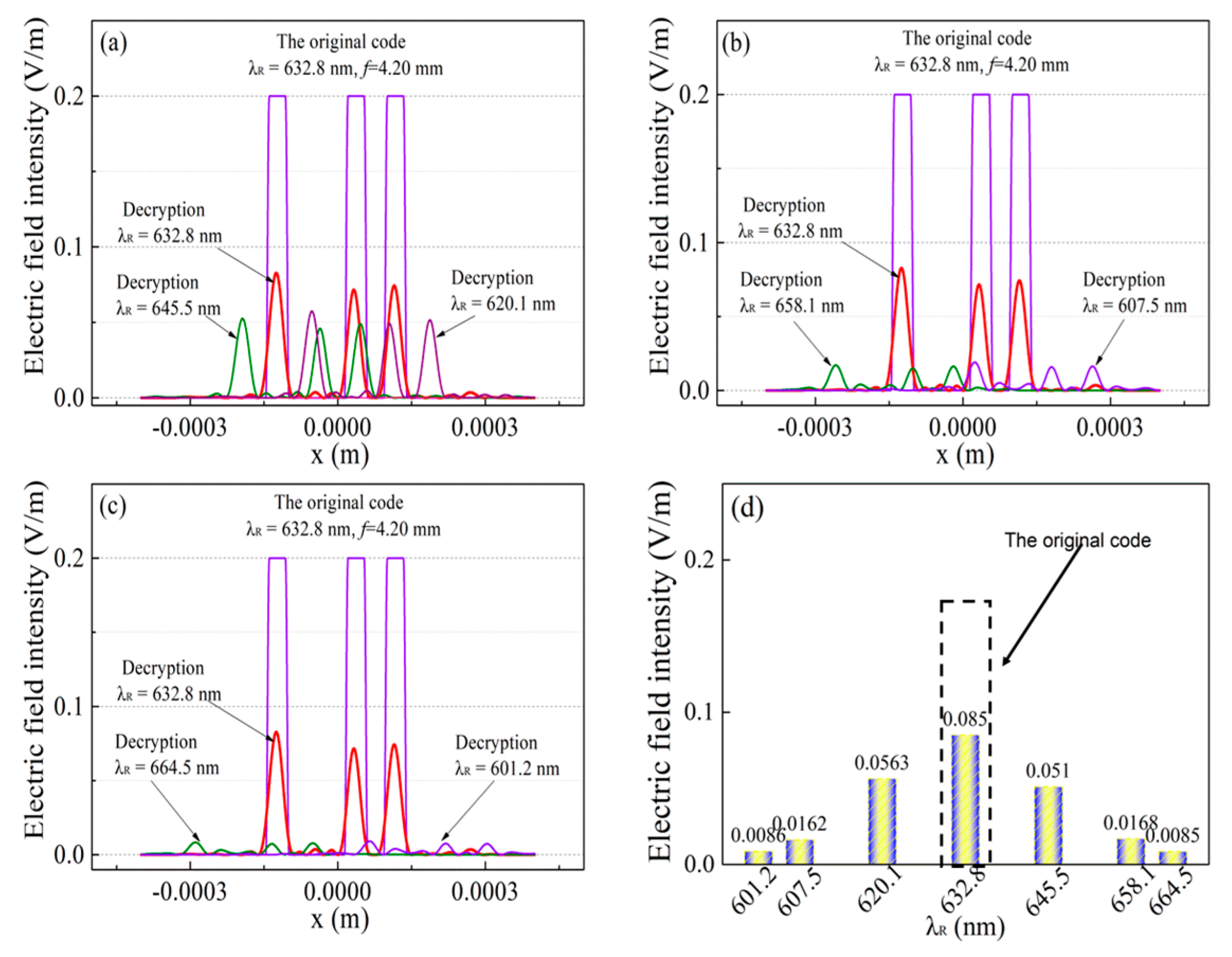
If the reference wave falls on the hologram that contains the IFP information, then a new object wave will be created. Previously, we supposed that a decryption’s key was chosen to be = 632.8 nm, as shown in Figure 6a. The Figure 6b shows that the decryption process will fail if a different key is selected, e.g., = 601.2 nm. Then, the original code with square pulses (e.g., “1011”) is compared with the decrypted code of the different reference wavelength, as shown in Figure 7. The reference wave is tuned from 601.2 nm to 664.5 nm and keeping a Fourier lens of focal length f value at 4.20 mm. In Figure 7a–c, comparisons between the original code of = 632.8 nm and that of the reference waves of (601.2 nm to 664.5 nm) are shown. We can see from these figures that the reference wave of 632.8 nm has the highest amplitude and exhibits optimal electric field strength to recover the original code, as shown in Figure 7d. Hence, the reference wavelength is considered as the first decryption key and the simulation is performed to make sure that the reference wavelength is accurate at the receiver during decryption process.
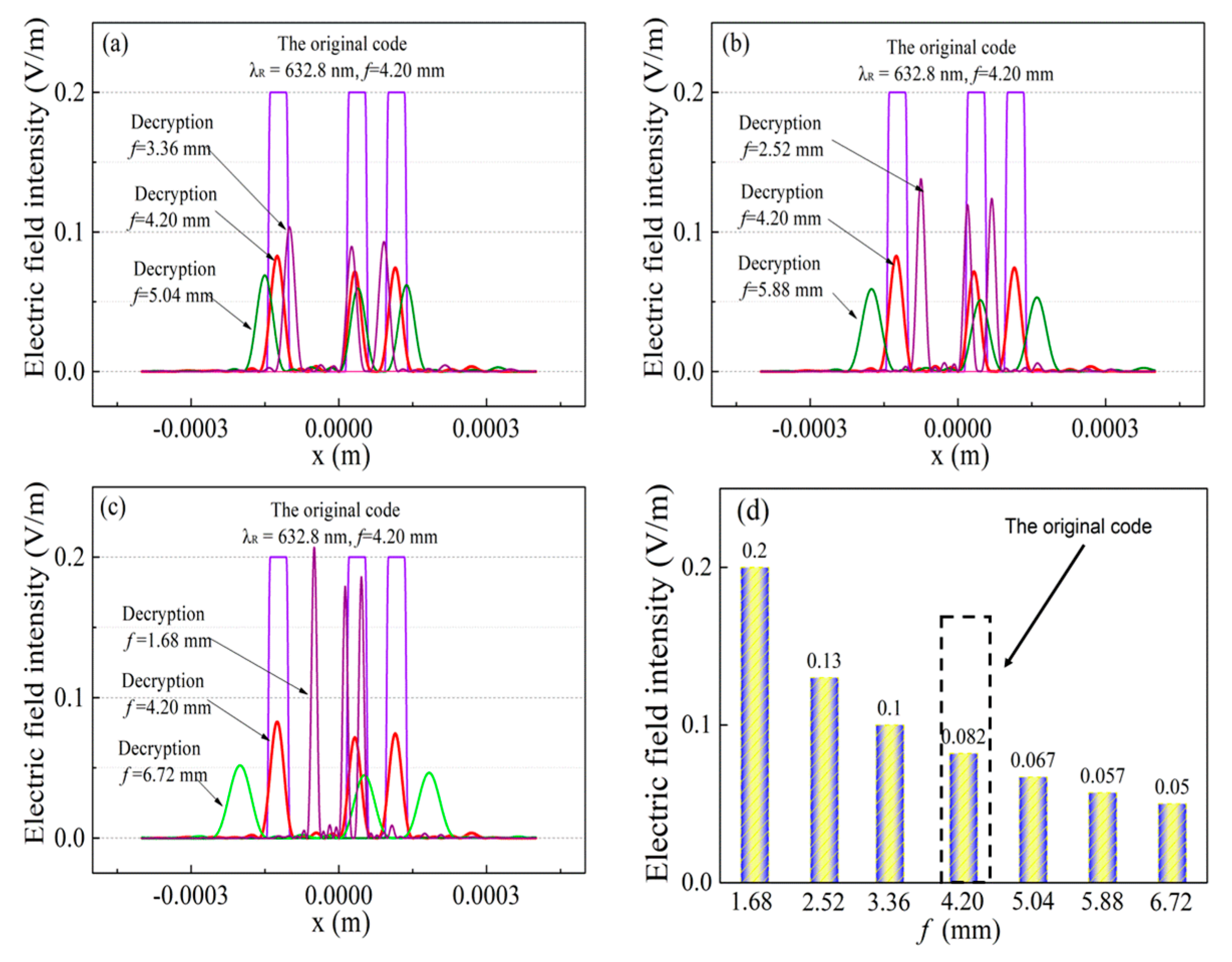
When the new object wave passes through the Fourier lens to be Fourier transformed, the focal length f is considered as a second decrypted key. An accurate focal length f is required to be verified, a computer-based simulation is conducted with various focal lengths f and a reference wave is maintained to be constant at = 632.8 nm. As shown in Figure 8, the original code with square pulses (e.g., “1011”) is compared by selecting various focal lengths f between 1.68 mm and 6.72 mm under the = 632.8 nm condition. Figure 8a–c shows that the focal length of f = 4.20 mm has better matching with the bit period of the original code than the other ones. Figure 8d shows that the focal length f = 4.20 mm does not have the highest amplitude. However, the wide period of the signal is located within the original bit’s period. Therefore, this signal with focal length f = 4.20 mm is an accurate value for decrypting data.
4. Security Evaluation
4.1. Bits Error Check
To determine the error of the decrypted code’s period with respect to the original code’s period, mean square error (MSE) [32,33] is calculated as:
where, M is the total number of samples in the code, is the value of the original encrypted code on the x axis, and is retrieval decrypted code.
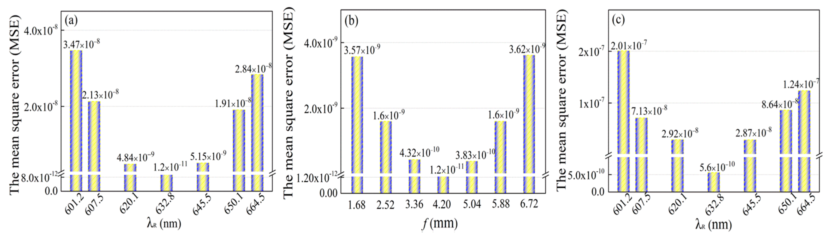
For the VOHE system, minimum MSE is obtained when the reference wave is set to 632.8 nm, as shown in Figure 9a. The minimum MSE is obtained when the focal length is at f = 4.20 mm, as shown in Figure 9b. If the Fourier lens of the VOHE system is removed, only holographic encryption remains and the reference wave is set to 632.8 nm, then a new result of the minimum MSE, as shown in Figure 9c, is higher than in (a) and (b). As a result, the minimum MSE values in (a) and (b) are smaller than in (c). It means that the VOHE system with the Fourier lens will have the highest performance.
4.2. Testing and Analysis
This section evaluates the security of the ERSA algorithm based on a statistical test suite for random and pseudorandom number generators for cryptographic applications NIST test [34]. Constructing robust and unpredictable random numbers are of paramount importance in most cryptographic applications. The encrypted message c of the ERSA algorithm (in Section 3.2) is required to be random enough against security attacks.
To verify the security of the encrypted message c, c is analyzed using the NIST method. This method calculates a p-value using the same key length for both RSA and ERSA. If the p-value has the highest value then the c value is considered as having better randomness. The p-value is frequently called a “tail probability”. If the p-value is <0.01, then it is concluded that the c value is nonrandom, otherwise the c value is random.
Table 2 shows a comparison between RSA and ERSA encryptions using the NIST tests. To comprehend this process, a numerical example is presented to evaluate both systems. We consider that has the same bit-size for both algorithms. In the ERSA algorithm, two complex functions, such as p = 155 + 168i, q = 187 + 122i, are selected (in Section 3.2), and two prime numbers, such as p = 49,277 and q = 47,221, are selected for the RSA algorithm.
Table 2 shows the NIST test results of the p-value generated by the ERSA and RSA algorithms, separately. As shown in the results, all tested items pass all tests except the linear complexity and rank tests. Additionally, eight items of the test’s results exhibit that the ERSA algorithm has higher-consistency results than RSA.
5. Conclusions
This work presents a new method of encrypting holographic information that can be employed for communications between deep submergence research vehicles to provide the highest security. The encryption model has been successfully simulated using COMSOL Multiphysics to simulate holograms and Fourier lens in the VOHE system. The system has two keys for encryption and decryption which must be coherent with each other. The wavelength λ was considered as a first key and the focal length f was considered as a second key.
Minimum mean square error (MSE) was used to evaluate the accuracy of the received signal. The evaluation results, which were based on Pollard’s rho method, indicate that we can obtain better security performance using the ERSA algorithm. Furthermore, security evaluation of the ERSA public key algorithm was also conducted using the NIST method for examining the randomness of the transmitted data.
We considered in this paper that the encryption process was done between only two nodes. In future research, we will further investigate the security of data transmissions over multinode network systems.
In the real-world environment and because of the sensitivity of the optical media, we expect that utilizing the optical and the acoustic waves together will provide high communication stability. Furthermore, it is able to achieve a high-speed transmission over long distances.
Author Contributions
Methodology, investigation, writing—original draft, and data curation, Y.P.; conceptualization, supervision, and project administration, T.N.; resources, S.Y., investigation, T.K. All authors have read and greed to the published version of the manuscript.
Funding
This research received no external funding.
Acknowledgments
The authors wish to thank Jianning Han, North University of China, China, for providing technical support.
Conflicts of Interest
The authors declare no conflict of interest.
References
- Spagnolo, G.S.; Cozzella, L.; Leccese, F. Underwater Optical Wireless Communications: Overview. Sensors 2020, 20, 2216. [Google Scholar]
- Diamant, R.; Campagnaro, F.; De Grazia, M.D.F.; Casari, P.; Testolin, A.; Calzado, V.S.; Zorzi, M. On the relationship between the underwater acoustic and optical channels. IEEE Trans. Wirel. Commun. 2017, 16, 8037–8051. [Google Scholar] [CrossRef]
- Roumelas, G.D.; Nistazakis, H.E.; Stassinakis, A.N.; Volos, C.K.; Tsigopoulos, A.D. Underwater optical wireless communications with chromatic dispersion and time jitter. Computation 2019, 7, 35. [Google Scholar] [CrossRef] [Green Version]
- Hong, Z.; Yan, Q.; Li, Z.; Zhan, T.; Wang, Y. Photon-counting underwater optical wireless communication for reliable video transmission using joint source-channel coding based on distributed compressive sensing. Sensors 2019, 19, 1042. [Google Scholar] [CrossRef] [Green Version]
- Doh, K.B.; Kim, K.; Poon, T.-C. Computer generated holographic image processing for information security. In Parallel and Distributed Computing: Applications and Technologies; Springer: Berlin, Germany, 2004; pp. 111–115. [Google Scholar]
- Hennelly, B.; Sheridan, J.T. Optical image encryption by random shifting in fractional fourier domains. Opt. Lett. 2003, 28, 269–271. [Google Scholar] [CrossRef] [PubMed] [Green Version]
- Zhou, N.; Li, H.; Wang, D.; Pan, S.; Zhou, Z. Image compression and encryption scheme based on 2d compressive sensing and fractional mellin transform. Opt. Commun. 2015, 343, 10–21. [Google Scholar] [CrossRef]
- Kong, D.; Cao, L.; Jin, G.; Javidi, B. Three-dimensional scene encryption and display based on computer-generated holograms. Appl. Opt. 2016, 55, 8296–8300. [Google Scholar] [CrossRef]
- Chatterjee, A.; Dhanotia, J.; Bhatia, V.; Prakash, S. Virtual Optical Encryption Using Phase Shifted Digital Holography and Rsa Algorithm. In Proceedings of the 2018 3rd International Conference on Microwave and Photonics (ICMAP), Dhanbad, India, 9–11 February 2018; pp. 1–2. [Google Scholar]
- Chang, H.T.; Wang, Y.-T.; Chen, C.-Y. Angle Multiplexing Optical Image Encryption in the Fresnel Transform Domain Using Phase-only Computer-Generated Hologram. Photonics 2020, 7, 1. [Google Scholar] [CrossRef] [Green Version]
- Tay, C.J.; Quan, C.; Chen, W.; Fu, Y. Color image encryption based on interference and virtual optics. Opt. Laser Technol. 2010, 42, 409–415. [Google Scholar] [CrossRef]
- Gao, Y.; Zhang, Z.; Liu, G. Three-dimensional display using computer-generated hologram based on virtual optics. Optik 2010, 121, 1395–1400. [Google Scholar] [CrossRef]
- Seo, Y.-H.; Choi, H.-J.; Bae, J.-W.; Kang, H.-J.; Lee, S.-H.; Yoo, J.-S.; Kim, D.-W. A new coding technique for digital holographic video using multi-view prediction. IEICE Trans. Inform. Syst. 2007, 90, 118–125. [Google Scholar] [CrossRef]
- Rivest, R.L.; Shamir, A.; Adleman, L. A method for obtaining digital signatures and public-key cryptosystems. Commun. ACM 1978, 21, 120–126. [Google Scholar] [CrossRef]
- Kaliski, B.; Staddon, J. Pkcs# 1: Rsa Cryptography Specifications Version 2.0. Available online: https://www.hjp.at/doc/rfc/rfc2437.html. (accessed on 18 September 2020).
- Wiener, M.J. Cryptanalysis of short rsa secret exponents. IEEE Trans. Inform. Theory 1990, 36, 553–558. [Google Scholar] [CrossRef] [Green Version]
- Kuwakado, H.; Koyama, K.; Tsuruoka, Y. A new rsa-type scheme based on singular cubic curves y 2 < cd02261. Gif > x 3 + bx 2 (mod n). IEICE Trans. Fundam. Electron. Commun. Comput. Sci. 1995, 78, 27–33. [Google Scholar]
- Elkamchouchi, H.; Elshenawy, K.; Shaban, H. Extended rsa cryptosystem and digital signature schemes in the domain of gaussian integers. In Proceedings of the 8th International Conference on Communication Systems, Singapore, 28 November 2002. [Google Scholar]
- Castagnos, G. An efficient probabilistic public-key cryptosystem over quadratic fields quotients. Finite Fields Their Appl. 2007, 13, 563–576. [Google Scholar] [CrossRef] [Green Version]
- Hariharan, P. Basics of Holography; Cambridge University Press: Cambridge, UK, 2002. [Google Scholar]
- Farr, N.; Bowen, A.; Ware, J.; Pontbriand, C.; Tivey, M. An Integrated, Underwater Optical/Acoustic Communications System. In Proceedings of the Oceans’10 IEEE Sydney, Sydney, Australia, 24–27 May 2010. [Google Scholar]
- Bandres, M.A.; Gutiérrez-Vega, J.C. Ince–gaussian beams. Opt. Lett. 2004, 29, 144–146. [Google Scholar] [CrossRef]
- O’Shea, D.C.; Suleski, T.J.; Kathman, A.D.; Prather, D.W. Diffractive Optics: Design, Fabrication, and Test; SPIE Press: Bellingham, WA, USA, 2004; Volume 62. [Google Scholar]
- Wang, W.-C.; Huang, C.-h.; Sung, P.-C.; Li, M.-H. Optical Interferometric Apparatus for Real-Time Full-Field Thickness Inspection and Method Thereof. U.S. Patent 9644947B2, 9 May 2017. [Google Scholar]
- Yue, Z.; Xue, G.; Liu, J.; Wang, Y.; Gu, M. Nanometric holograms based on a topological insulator material. Nat. Commun. 2017, 8, 1–5. [Google Scholar] [CrossRef] [Green Version]
- Bányász, I. Refractive index modulation vs. Before-bleach optical density modulation characteristics of silver halide phase holograms. Opt. Commun. 2005, 244, 79–91. [Google Scholar] [CrossRef]
- Yang, P.; Nagase, T. Analysis of a virtual optical encryption holographic system: Decrypted code using the multiple-bit virtual optical encryption holographic system based on the comsol multiphysics. In Proceedings of the 2019 6th International Conference on Systems and Informatics (ICSAI), Shanghai, China, 2–4 November 2019. [Google Scholar]
- Stergiopoulos, G.; Kandias, M.; Gritzalis, D. Approaching encryption through complex number logarithms. In Proceedings of the 2013 International Conference on Security and Cryptography (SECRYPT), Reykjavik, Lceland, 29–31 July 2013. [Google Scholar]
- Anand, P.R.; Bajpai, G.; Bhaskar, V. Real-time symmetric cryptography using quaternion julia set. IJCSNS Int. J. Comput. Sci. Netw. Secur. 2009, 9, 20–26. [Google Scholar]
- Pollard, J.M. A monte carlo method for factorization. BIT Numer. Math. 1975, 15, 331–334. [Google Scholar] [CrossRef]
- Efremidis, N.K.; Chen, Z.; Segev, M.; Christodoulides, D.N. Airy beams and accelerating waves: An overview of recent advances. Optica 2019, 6, 686–701. [Google Scholar] [CrossRef] [Green Version]
- Wackerly, D.; Mendenhall, W.; Scheaffer, R.L. Mathematical Statistics with Applications; Cengage: Boston, MA, USA, 2014. [Google Scholar]
- Swathika, E.; Karthika, N.; Janet, B. Image encryption and decryption using chaotic system. In Proceedings of the 2019 IEEE 9th International Conference on Advanced Computing (IACC), Tiruchirappalli, India, 13–14 December 2019. [Google Scholar]
- Pareschi, F.; Rovatti, R.; Setti, G. On statistical tests for randomness included in the nist sp800-22 test suite and based on the binomial distribution. IEEE Trans. Inform. Forensics Secur. 2012, 7, 491–505. [Google Scholar] [CrossRef]
Figure 1.
Model of the virtual optical holographic encryption (VOHE) system. (a) Encryption process; (b) Decryption process.
Figure 1.
Model of the virtual optical holographic encryption (VOHE) system. (a) Encryption process; (b) Decryption process.

Figure 2.
A schematic diagram of ERSA.

Figure 3.
The average output loop of Pollard’s rho method.

Figure 4.
(a) The object message e.g., “1011”. (b) The electric field amplitude

Figure 5.
The encryption strength and electric field at . (Inset: the interference fringe pattern (IFP) at a 45-degree angle).
Figure 5.
The encryption strength and electric field at . (Inset: the interference fringe pattern (IFP) at a 45-degree angle).

Figure 6.
The decryption strength and electric field at: (a) , (b) . (Inset: the IFP with at a 45-degree angle).
Figure 6.
The decryption strength and electric field at: (a) , (b) . (Inset: the IFP with at a 45-degree angle).

Figure 7.
Comparisons between the original code of 632.8 nm and the decrypted code of different reference waves : (a) 620.1 nm, 632.8 nm and 645.5 nm, (b) 607.5 nm, 632.8 nm and 658.1 nm, and (c) 601.2 nm, 632.8 nm and 664.5 nm; (d) electric field strength of data decrypted with different reference waves from 601.2 nm to 664.5 nm.

Figure 8.
Comparisons between the original code of 4.20 mm and the decrypted code of different focal lengths f: (a) 3.36 mm, 4.20 mm and 5.04 mm, (b) 2.52 mm, 4.20 mm and 5.88 mm, and (c) 1.68 mm, 4.20 mm and 6.72 mm; (d) electric field strength of data decrypted with different focal lengths from 1.68 mm to 6.72 mm.

Figure 9.
The MSE of data decrypted using the different (a) reference waves from 601.2 nm to 664.5 nm and (b) focal lengths from 1.68 mm to 6.72 mm. (c) The MSE of data decrypted for the other method (remove the Fourier lens from the VOHE system and leaving only holographic encryption) using different reference waves from 601.2 nm to 664.5 nm.


Table 1.
Details of N and the key size of RSA and ERSA.
| Algorithm | Modulus N | The Size of Key |
|---|---|---|
| RSA | Len(x) | |
| ERSA | Len(x) + Len(y) |
Table 2.
NIST test results.
| Test Items | ERSA | RSA | |
|---|---|---|---|
| p-Value | p-Value | ||
| 1 | Frequency | 0.548506 | 0.423711 |
| 2 | Block frequency | 0.548506 | 0.423711 |
| 3 | Cumulative sums | 0.958638 | 0.322973 |
| 4 | Runs | 0.661694 | 0.203323 |
| 5 | Longest run | 0.810056 | 0.732505 |
| 6 | Rank | 0.000000 | 0.000000 |
| 7 | Approximate entropy | 0.758892 | 0.322153 |
| 8 | Serial | 0.999877 | 0.498531 |
| 9 | Linear complexity | 0.000000 | 0.000000 |
| 10 | FFT | 0.646355 | 0.168669 |
© 2020 by the authors. Licensee MDPI, Basel, Switzerland. This article is an open access article distributed under the terms and conditions of the Creative Commons Attribution (CC BY) license (http://creativecommons.org/licenses/by/4.0/).
Share and Cite
MDPI and ACS Style
Peng, Y.; Nagase, T.; You, S.; Kanamoto, T. A VOHE System for Underwater Communications. Electronics 2020, 9, 1557. https://doi.org/10.3390/electronics9101557
AMA Style
Peng Y, Nagase T, You S, Kanamoto T. A VOHE System for Underwater Communications. Electronics. 2020; 9(10):1557. https://doi.org/10.3390/electronics9101557
Chicago/Turabian StylePeng, Yang, Tomoyuki Nagase, Shan You, and Toshiki Kanamoto. 2020. "A VOHE System for Underwater Communications" Electronics 9, no. 10: 1557. https://doi.org/10.3390/electronics9101557
Note that from the first issue of 2016, this journal uses article numbers instead of page numbers. See further details here.