Fault Current Limiters in Power Systems: A Comprehensive Review


Department of Electrical Engineering, King Fahd University of Petroleum & Minerals, Dhahran 31261, Saudi Arabia
*
Author to whom correspondence should be addressed.
Energies 2018, 11(5), 1025; https://doi.org/10.3390/en11051025
Submission received: 6 March 2018
/
Revised: 13 April 2018
/
Accepted: 17 April 2018
/
Published: 24 April 2018
(This article belongs to the Section F: Electrical Engineering)
Abstract
:Power systems are becoming more and more complex in nature due to the integration of several power electronic devices. Protection of such systems and augmentation of reliability as well as stability highly depend on limiting the fault currents. Several fault current limiters (FCLs) have been applied in power systems as they provide rapid and efficient fault current limitation. This paper presents a comprehensive literature review of the application of different types of FCLs in power systems. Applications of superconducting and non-superconducting FCLs are categorized as: (1) application in generation, transmission and distribution networks; (2) application in alternating current (AC)/direct current (DC) systems; (3) application in renewable energy resources integration; (4) application in distributed generation (DG); and (5) application for reliability, stability and fault ride through capability enhancement. Modeling, impact and control strategies of several FCLs in power systems are presented with practical implementation cases in different countries. Recommendations are provided to improve the performance of the FCLs in power systems with modification of its structures, optimal placement and proper control design. This review paper will be a good foundation for researchers working in power system stability issues and for industry to implement the ongoing research advancement in real systems.
1. Introduction
Nowadays, the transmission lines of power systems are being stressed to transfer larger amounts of power, much closer to their thermal limit, than were considered when built. Power resources are limited and are increasingly more uncertain and variable. The integration of several renewable energy resources, including large-scale wind farms, into the existing grid is a great challenge for power system researchers. It increases the complexity of the electric networks with an inherently high short circuit rate. Generally, the electric networks are vulnerable to AC/DC faults and sophisticated protection apparatus and procedures need to be developed to avoid costly or even irremediable damage. Current limiting reactors are used in power systems for limiting short circuit currents and avoiding damage to the power system due to excessive fault currents. However, current limiting reactors have impedance during normal operation of the system [1].
The stability and security of electric power systems has become increasingly significant due to their complex nature. The application of a fault current limiter is one of the promising solutions to the stability and security issues of power systems. Different kinds of fault current limiters, such as resistive, inductive, superconducting, non-superconducting, flux-lock, DC reactor and resonance FCL, have been offered for limiting fault currents and improving the dynamic stability of power systems [2,3,4,5,6]. Resistive-type and inductive-type FCLs provide nearly zero impedance under normal operating conditions, whereas they provide high-impedance resistors or inductors in faulty conditions. Recently, a number of practical superconducting fault current limiter (SFCL) devices have been effectively developed and verified by in-grid tests. The present focus on applied superconductivity technology to build SFCL devices has been moving from the 10-kV distribution level [7,8] to the 100-kV transmission level [8,9].
This paper provides a broad view of the applications of several superconducting and non-superconducting FCLs in different branches of power networks. Structure and control techniques for several FCLs are discussed. Several optimal parameter selection and optimal placement techniques for FCLs are provided. Practical implementation cases in different countries with field tests are discussed. Lastly, current challenges for FCL application are addressed and future works are recommended.
The paper is organized as follows: Section 2 provides a general overview of the application of FCLs in several branches of power systems; the structure and working principles of superconducting and non-superconducting FCLs are discussed in Section 3 and Section 4 respectively; optimal placement techniques for FCLs are provided in Section 5; the practical implementation issues for FCLs in different countries and field-testing results are discussed in Section 6; stability augmentation in different branches of power systems with FCLs are presented in Section 7; current challenges for FCLs application and some future works are recommended in Section 8; and finally, Section 9 highlights the major conclusions of this survey.
2. Superconducting and Non-Superconducting FCLs
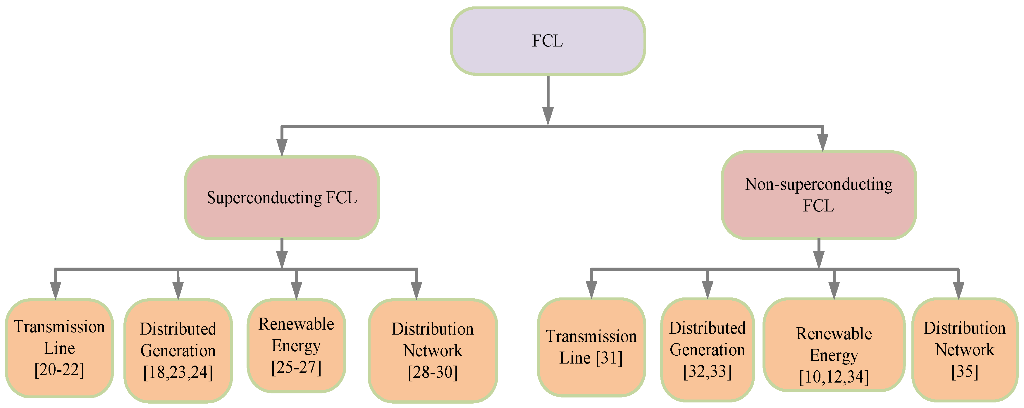
Fault current limiters (FCLs) are considered serious candidates to be inserted into electrical grids in order to prevent short-circuit damage and the inevitable upgrading of the system equipment. Mainly, two types of FCLs are extensively applied in power systems: non-superconducting [10,11,12,13] and superconducting [14,15,16,17,18,19]. Superconducting FCLs have been applied in different parts of the power network such as renewable power generation, distribution generation, transmission system, distribution network [18,20,21,22,23,24,25,26,27,28,29,30]. Also, non-superconducting types FCLs have been employed in several branches of power system such as generation, transmission, distribution network for improving dynamic performance by limiting fault current [10,12,31,32,33,34,35]. The tree diagram shown in Figure 1 summarizes the different applications of superconducting and non-superconducting FCLs in power systems.
Both superconducting FCL and non-superconducting FCL have been extensively applied in transmission and distribution networks and renewable energy systems for different purposes such as stability enhancement, protection improvement, fault current reduction and fault ride through capability enhancement. Main advantages and disadvantages of superconducting and non-superconducting FCLs are summarized in Table 1.
3. Superconducting FCLs
Depending on the structure and operating principle, superconducting fault current limiters (SFCLs) can be categorized as different types: Non-inductive reactor, inductive, transformer, resistive, hybrid, flux-lock and magnetic-shield.
3.1. Non-Inductive Type SFCL
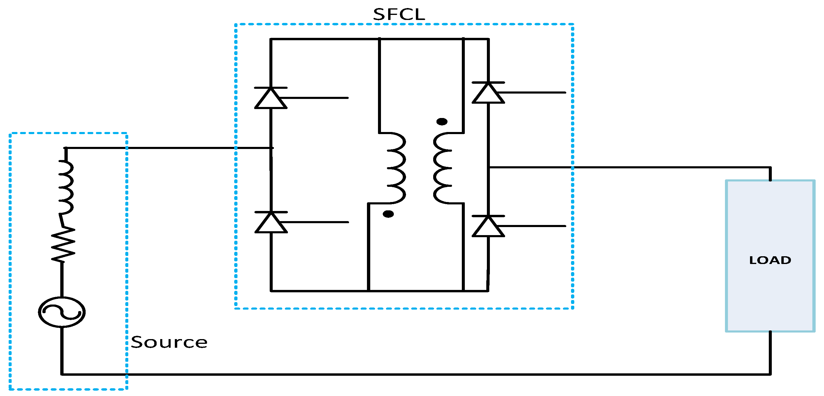
A schematic diagram of non-inductive type SFCL is shown in Figure 2, which is made of two superconducting coils [60].
A current limiting coil and a trigger coil are connected in anti-parallel and are magnetically coupled well. Different types of configurations like a coaxial coil arrangement and a bifilar winding arrangement were compared. The bifilar winding arrangement was found to be superior to have a high impedance ratio [60].
3.2. Inductive Type SFCL
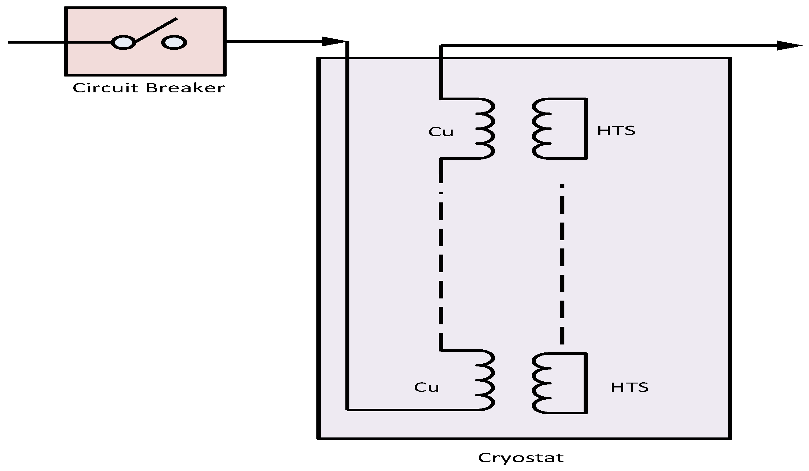
Inductive type SFCL has two coaxial windings and an optional magnetic core [61]. Primary winding is made up of copper (Cu), whereas secondary winding is made up of a high temperature superconductor (HTS). The SFCL is cooled in a liquid nitrogen bath. The electrical connection diagram of inductive SFCL is shown in Figure 3.
During the steady state mode of the power system, nearly zero impedance is shown by inductive SFCL as the zero impedance of the secondary superconducting winding is reflected to the primary. However, during system contingencies, resistance in the secondary is reflected in the primary circuits to limit the fault currents.
3.3. Transformer Type SFCL
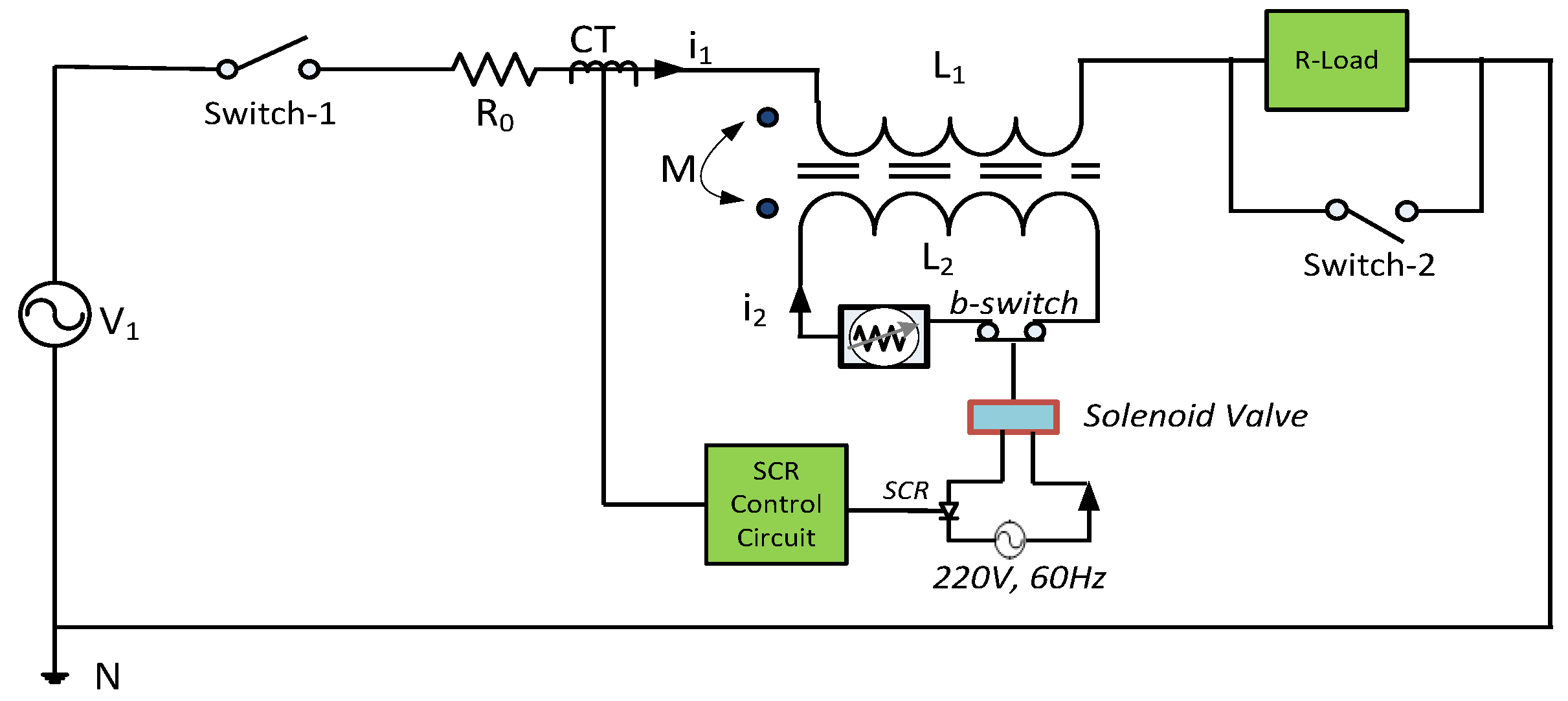
Enhancement of supply reliability and power system stability have been observed with the transformer type SFCL [52,62,63,64,65,66,67,68]. The primary side of the transformer type SFCL is connected in series with the load whereas the secondary side is connected in series with superconductors. The transformer type fault current limiter with vacuum interrupter is shown in the Figure 4. In Figure 4, L1 and L2 are the inductance in primary and secondary respectively. M is the mutual inductance between the primary and secondary coils of the transformer.
Upon the occurrence of faults, superconductors in the secondary side of the transformer are quenched, consequently, fault current in the secondary is limited to a lower value. Due to the current limiting in the secondary, fault current in the primary side is limited as well.
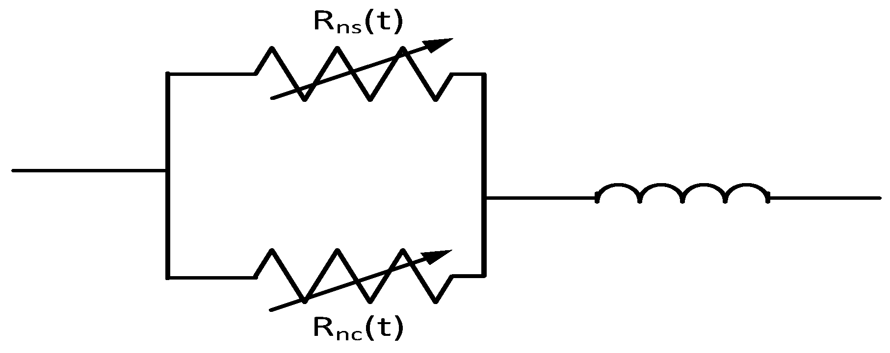
3.4. Resistive Type SFCL
Resistive type SFCL can improve the transient stability of the power system by suppressing the level of fault currents in a quick and efficient manner [5,69,70,71,72,73,74,75,76,77,78,79]. A very simple structure of resistive SFCL is shown in Figure 5 consisting of nth units of stabilizing and superconducting resistances in parallel [5]. Coil inductance with nth units is connected in series with the parallel resistive branch.
In the normal steady state condition, the values of stabilizing (Rns) and superconducting (Rnc) resistances are zero. However, during fault conditions, these resistances become nonzero time-varying parameters to maintain superconducting states according to their unique characteristics. The value of the coil inductance is kept as small as possible in order to have minimal AC loss during normal operation. Therefore, the effect of the inductor during steady state operation is ignored.
A long length of the superconductor is needed to make a high voltage and high current system in case of resistive and inductive type SFCLs. However, this required length is significantly reduced in hybrid SFCL, which makes it commercially applicable [80].
3.5. Hybrid SFCL
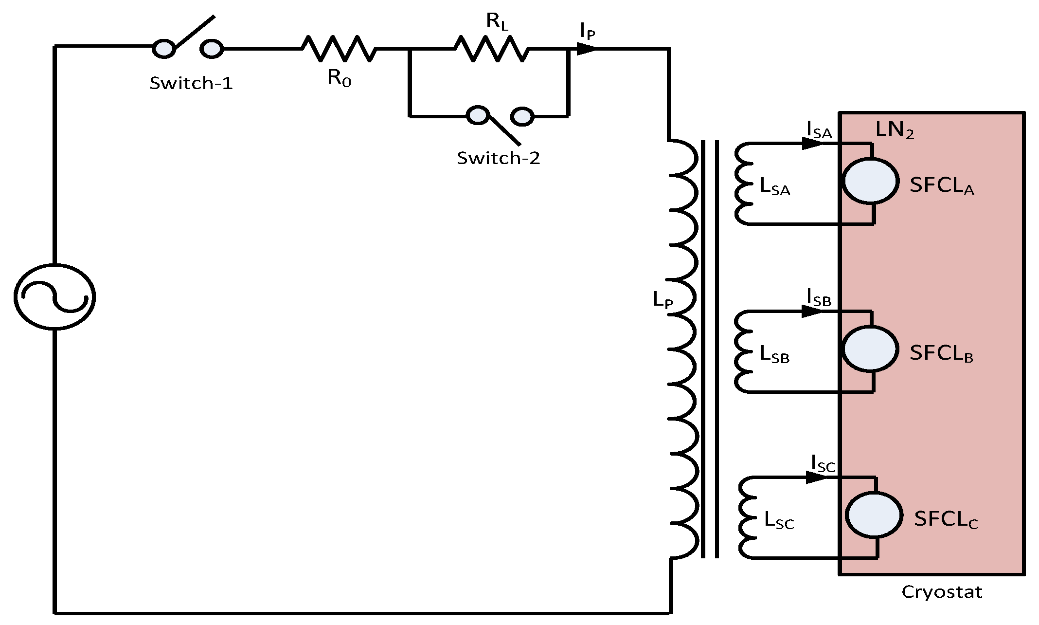
Due to the slight critical current differences between the several units, resistive SFCL faces difficulty in quenching simultaneously between the units; however, this problem can be solved with hybrid SFCL [81]. Hybrid SFCL is proposed for limiting fault current and improving dynamic performance of power system [80,81,82,83]. A hybrid type SFCL has a primary winding and several secondary windings as shown in Figure 6 [81]. Each of the secondary windings is connected in series with a superconducting resistive unit. In Figure 6, LP is inductance in the primary winding of the transformer and LSA, LSB, LSC and ISA, ISB, ISB are the inductances and currents of secondary windings A, B and C respectively.
During normal operation, resistance of the superconducting units connected in series with the secondary windings is zero. Therefore, current (IP) flows through the power system without any loss. When fault appears on the system, superconducting unit is quenched and fault current is limited. In this way, hybrid SFCL has almost no effect on the system performance during normal operation and limits fault current during contingencies.
3.6. Flux-Lock Type SFCL
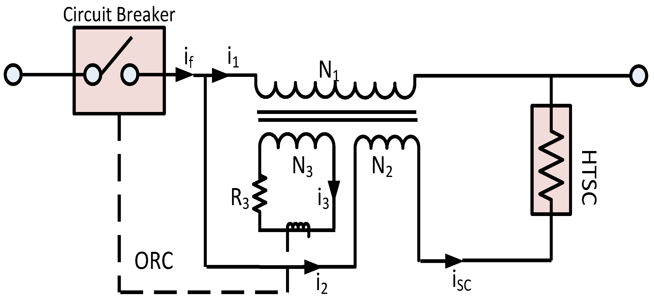
Among several of the SFCLs, the flux-lock type SFCL has less power burden of the high temperature superconducting (HTSC) element [53]. Short circuit current in power system can be limited with the flux-lock type fault current limiter during different contingencies [36,41,53,84,85,86,87,88]. The configuration of the flux-lock type SFCL with over current relay is shown in the Figure 7 where N1, N2, N3 and i1, i2, i3 represent coil-1, coil-2 and coil-3 and their currents, respectively. ORC stands for over current relay.
As shown in Figure 7, the flux-lock type SFCL has two main parts— the current limiting part and the current interrupting part. The current limiting part consists of two parallel-connected coils and a high temperature superconductor (HTSC) connected in series with one of the coils. The current interrupting part consists of an over current relay driven by one of the parallel coils and a circuit breaker. During normal operation, zero voltage is induced across the coil as the magnetic fluxes generated in two coils are cancelled out. In faulty conditions, fault current is limited by the voltage generations across the coils.
3.7. Magnetic Shield Type SFCL
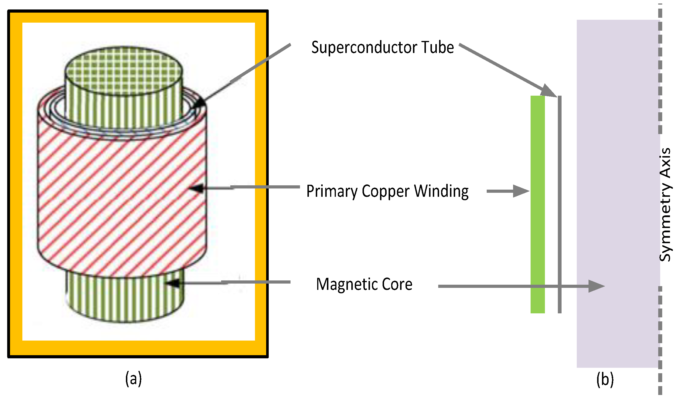
Magnetic shield type SFCLs have been reported in References [50,51,89,90,91,92,93,94]. They consist of a primary copper coil and secondary high temperature superconductor (HTS) tube wound around a magnetic iron core [93] as shown in Figure 8. In the magnetic shield SFCL, screen currents thwart flux penetration into the iron core during standard operation as the HTS tube is fixed in between the primary copper winding and the magnetic core.
During fault conditions, superconducting to a normal transition value is increased as the current exceeds critical value of HTS elements. Therefore, the resistance of the HTS tube is replicated in the primary circuit and magnetic flux infiltrates into the iron core augmenting impedance of the limiter.
Table 2 summarizes superconducting FCLs in terms of cost, advantages, limitation and applications and so forth.
4. Non-Superconducting FCLs
Generally, superconducting fault current limiters have been extensively used in power systems. However, non-superconducting fault current limiters could play an important role in reducing fault current and improving the dynamic stability of power systems with minimal cost compared to superconducting fault current limiters [10,34,97]. There are several types of non-superconducting fault current limiters as follows.
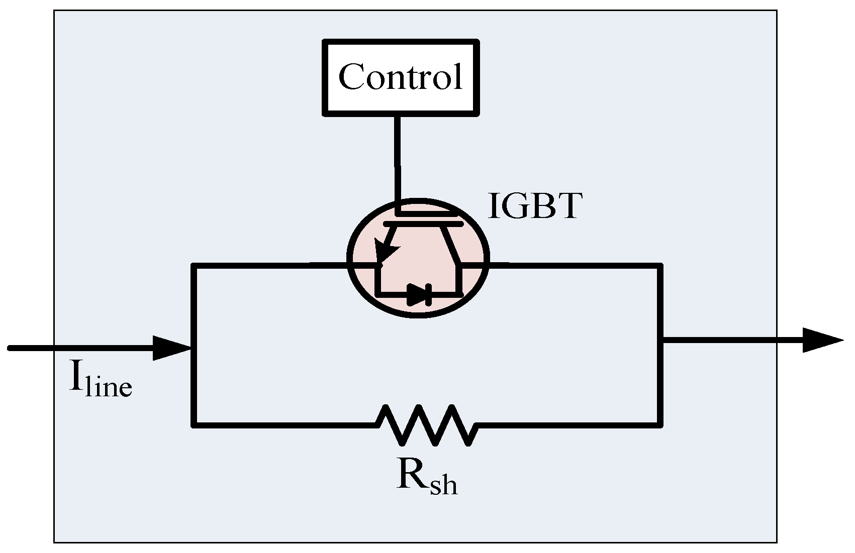
4.1. Series Dynamic Braking Resistor (SDBR)
SDBR is a non-superconducting FCL that has been extensively used in power systems, especially for the fault ride through capability enhancement of wind farms [54,55,56,57,58,59]. SDBR consists of a resistor in parallel with a switch. The switch is turned on and off based on the occurrence of a fault in the system. Due to fast response, IGBT is used as a switch as shown in Figure 9.
During normal operation, IGBT is turned on and the braking resistor is bypassed. Therefore, the SDBR has no effect on the system during normal condition of the grid. At the inception of grid fault, voltage at the point of common coupling (Vpcc) decreases and becomes lower than the predefined reference voltage (Vref). IGBT is turned off at this condition and braking resistor comes in series with the line to limit the sharp increase in line current. Braking resistor continues to be in series with the line until Vpcc becomes greater than Vref. When Vpcc surpasses Vref, IGBT is turned on and system returns to its normal operation.
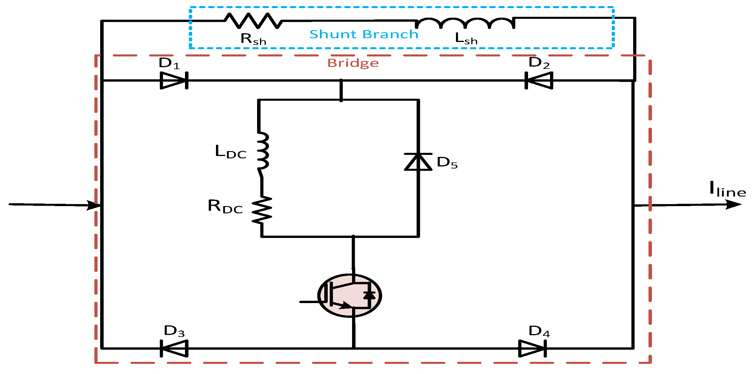
4.2. Bridge Type Fault Current Limiter (BFCL)
The main function of BFCL is to insert resistance and induction at the inception of a fault. It does not require superconductive characteristics for its operation, thus it has less application costs compared to other fault current limiting devices. The bridge part is composed of a diode rectifier, a very small dc limiting reactor (LDC), a small DC resistance (RDC), a commercially available semiconductor (IGBT) switch (CM200HG-130H) and a freewheeling diode. The main shunt branch is connected in parallel with the bridge part. It consists of a series of connected resistance and reactance (Rsh + jωLsh).
During normal operation, the IGBT switch is turned on and current flows through the path D1-LDC-RDC-D4 for positive half cycle of the signal. Then, current conducts through the path D2-LDC-RDC-D3 for negative half cycle of the signal. As the current through the LDC has unified direction during this normal operating condition LDC is charged to the peak of the line current and essentially behaves like short circuit and it has negligible voltage drop. Consequently, BFCL has no impact on the system in normal operating conditions. During contingencies, the IGBT switch is turned off and essentially the bridge behaves like an open circuit. So, the shunt path of the BFCL comes into operation and limits the fault current. At the same time, the freewheeling diode provides a discharge path for reactor (LDC). It is worth mentioning that during fault initiation LDC the line current tends to increase drastically; however, LDC limits this current. Therefore, the IGBT switch is saved from high di/dt.
4.3. Modified Bridge Type Fault Current Limiter (MBFCL)
The structure of the bridge of the fault current limiter is rearranged to enhance low voltage ride through the capability of fixed speed and variable speed wind farms [49,104]. This new topology is named a modified bridge type fault current limiter (MBFCL). In BFCL shunt path consists of a series connected resistor and inductor. However, an inductor is omitted in MBFCL because it discharges when the shunt path is disconnected. During normal operation, MBFCL bridge is short-circuited as the IGBT gate signal is high, thus shunt branch resistance is bypassed. When a fault appears on the system, the IGBT gate signal becomes low by proper control action, the bridge part of the MBFCL is eventually open and shunt resistance is inserted in the line to limit the fault current.
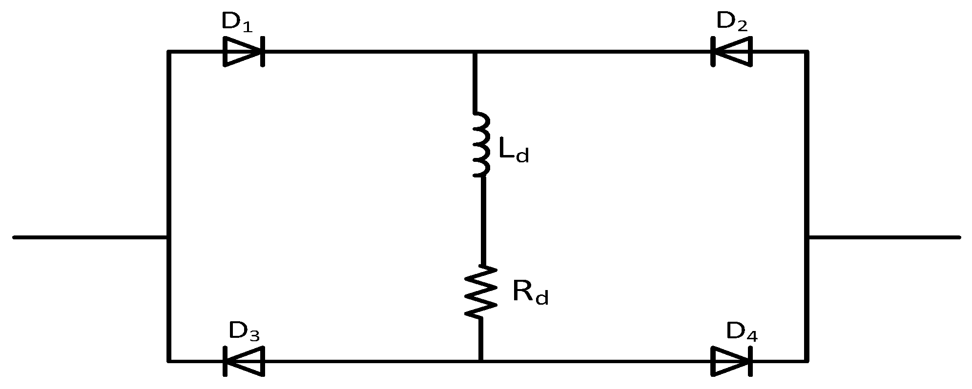
4.4. DC Link Fault Current Limiter (DLFCL)
The DC link fault current limiter is proposed for fault ride through capability enhancement of an inverter based distributed generation system [32]. The non-superconducting DTFCL module is composed of a diode bridge and an inductive coil that has an inductor Ld and very small resistance Rd as shown in Figure 11.
During normal operation, the DC reactor has a negligible impact. However, the reactor can effectively suppress severe di/dt and it can limit fault current successfully over the fault duration.
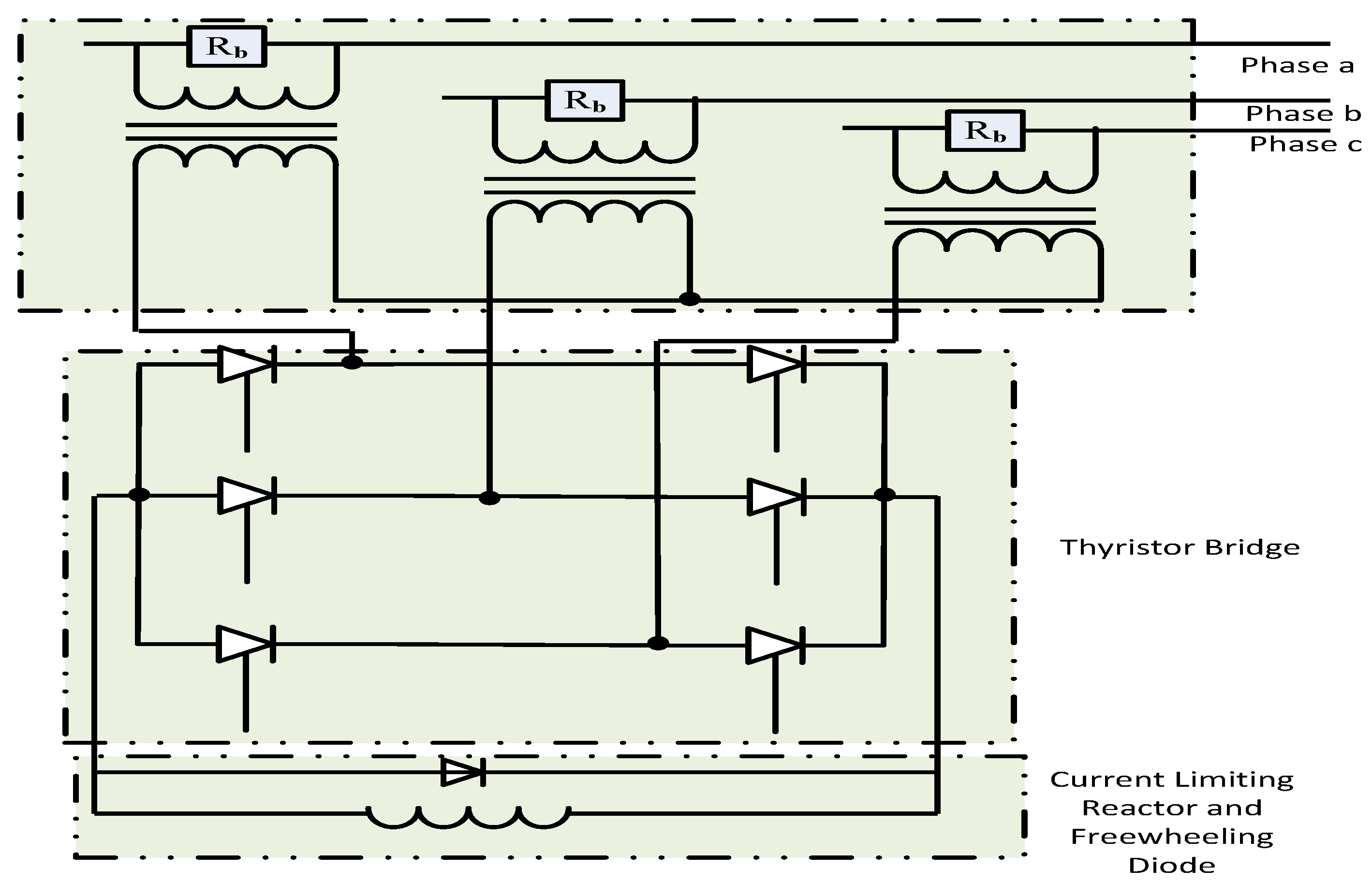
4.5. Transformer Coupled BFCL
A transformer coupled bridge type fault current limiter is presented [105] for low voltage ride through (LVRT) capability enhancement of a doubly fed induction generator (DFIG). The schematic diagram of the fault current limiter is shown in Figure 12. A bypass resistor (Rb) is used to absorb the majority of the current harmonics during normal operation and to reduce voltage spikes.
In a steady state system, all the thyristors are kept turned on and limiting reactors are bypassed. During system disturbances, gate signals of the thyristors are removed and a limiting reactor is inserted to limit fault current.
Table 3 summarizes different types of non-superconducting fault current limiters.
5. Optimal Parameters and Placement of Fault Current Limiters
The optimal location for FCLs in a power network has several potential benefits. These include enhancing the system reliability and security, reducing fault current and voltage sag, improving fault ride through capability and increasing the interconnection of renewable energy. Several optimal placement techniques have been reported in the literature [14,18,23,106,107,108,109,110,111,112,113]. Number of FCLs units, optimal parameters and optimal positions are considered for the placement of the FCLs in power system with several objectives like fault current reduction, reliability and stability improvement, FCL cost reduction and optimization of operating time of the over current relays. Some of the works focused on optimal placement mainly with single objective function as either fault current reduction [114,115] or stability enhancement [113]. Since there is the tradeoff among several objectives, enhancing one of them might lead to the deterioration of the others. Multiobjective optimization techniques [18,23,107,116] have been reported to solve the above mentioned problem. However, most of the optimal placement techniques do not take into account uncertainties in power systems, especially the unpredictable variations in the status of a DG, wind and PV systems when determining the best location for SFCL [14]. New placement algorithms can be developed considering several networks uncertainties for better performance. Table 4 summarizes optimal placement parameter selection techniques for different superconducting FCLs.
6. Field Tests of FCLs
Although short circuit tests can be conducted to demonstrate current limiting capability of any developed SFCL, a field test is necessary to validate the performance and reliability. SFCL practical installing issues and field tests have been reported [17,46,47,48,118,119,120,121,122,123]. In many countries FCLs have been practically installed and field tests have been done with results and recommendations for further study. Table 5 below shows field test results from different countries.
Long term operational tests have been performed in majority of the field tests to guarantee the reliability and performance of the SFCL devices. For example, the device temperature test to check whether it is within or above the tolerance value [47]. Determination of operational cost by measuring power consumption is one of the main requirements during long term operation tests of SFCL. However, only operational cost of hybrid SFCL [1,47] has been determined and compared with circuit breaker replacement cost and other damages to the power system equipment due to high fault currents. More discussion and feasibility analysis of other types of SFCLs are required with rigorous filed tests. Furthermore, non-superconducting solid state FCLs grid operation and field tests with feasibility analysis should be done in future work before real time grid integration.
7. FCLs in Stability and Fault Ride Through Capability Enhancement
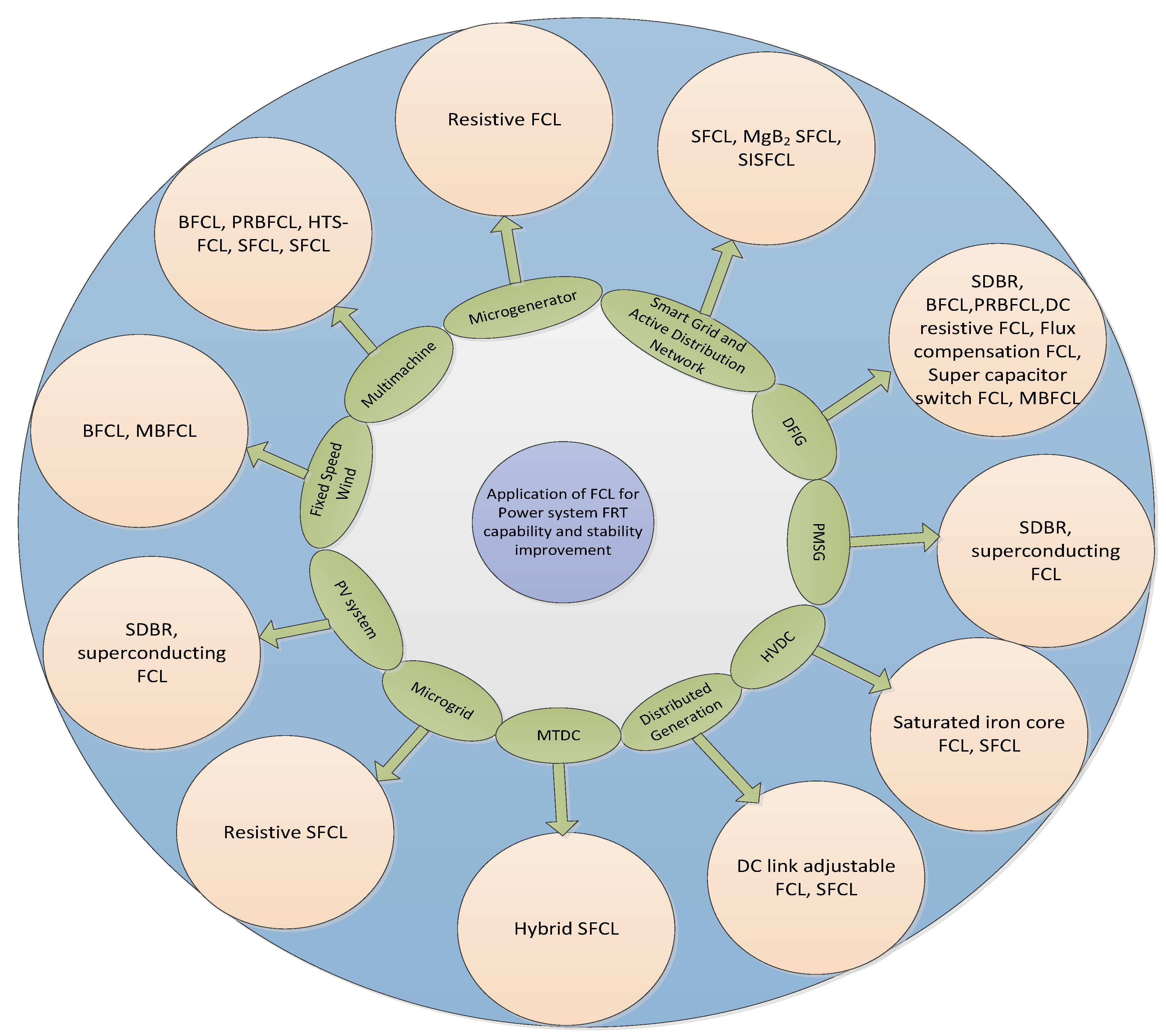
Due to the increased electrical power demand the fault levels in power systems increase causing severe damage to power system equipment. One of the main ways of enhancing power system stability and reliability is to interconnect the power systems for exchanging power among each other [124,125,126,127]. However, when fault occurs in the system, fault current is contributed to the fault point from all the interconnected parts which restrict interconnection to a certain extent so that the fault current could be kept within the breaking capability of the circuit breakers. Another feasible way is to employ fault current limiters in order to enhance reliability and stability of the interconnected power systems [19,33,34,54,104,128,129,130,131,132,133,134,135,136,137,138,139,140,141,142,143,144]. Implementation of SFCLs has been reported [145,146] for limiting fault current as well as improving stability of active distribution network by reducing impact on circuit breaker. In [145], different types of SFCLs have been applied in a medium voltage active distribution network in order to investigate their impact on transient recovery voltage of circuit breaker. This investigation shows the capability of SFCLs in reducing both the magnitude and rate of rise of transient recovery voltage on circuit breaker which in turn improves system stability. Stability enhancement of microgrids, smart grids, multimachine systems, PV systems, high voltage direct current (HVDC) and wind systems has been observed with different fault current limiters such as SFCL, BFCL, DC link FCL, super capacitor switch FCL and standard iron core FCL as shown in Figure 13. As clearly visualized in the Figure 13, the superconducting FCLs have been examined with many branches of power system. However, non-superconducting FCL have been applied in few branches of power system.
Different types of non-superconducting FCLs like bridge type fault current limiter (BFCL), parallel resonance bridge type fault current limiter (PRBFCL) have been examined in DFIG based wind integration, multimachine system and fixed speed wind system. Application of these non-superconducting FCL could be investigated in HVDC, smart grid, microgrid and multi-terminal HVDC (MTDC). Till date, some of the SFCLs have been practically implemented in some power systems in the world. However, non-superconducting fault current are yet to be implemented in real power system. Diodes and IGBT switches are mainly required for non-superconducting FCLs which can be implemented easily [104]. Moreover, required inductor and resistor for current limiting part are non-superconducting in nature which will reduce implementation cost excessively compared to superconducting fault current limiter for future in power system.
8. Industry Practices/Practical Implementation
Several experiments at industry levels or laboratory are performed prior to practical implementation of superconducting fault current limiters (SFCLs) in real system, especially for high voltage application of SFCL. To establish the winding technique of the largest high temperature superconductor (HTS) coil and build up the superconducting magnet system for high voltage application, for instance, 500 kV SFCL, short sample test of HTS wire and tension test of double pancake coil are performed in [147].
In [148], no-insulation (NI) coil is firstly applied in an inductive SFCL prototype as the secondary winding, which is magnetically coupled with the primary winding. A two-winding structure air-core prototype was developed with copper wire in primary winding and NI coils in secondary winding and this developed structure was brought under different experiments like short circuit test and impedance variation test which are needed before large-scale industrial production.
In South Korea, most of the power plants are located in the southern regions, while 40% of the loads are in northern regions. And, due to social and environmental constraints, installing additional power plant in southern region is difficult; as a result, more generators are added in the existing sites which cause more fault currents and instability in the systems. To resolve this issue, in [118], a novel hybrid type SFCL is presented. Although, in Korea, 22.9 kV hybrid SFCL was installed before, voltage level is still not as expected and recovery time is larger. This newly developed hybrid SFCL solves these problems.
In the framework of development of HTS based SFCL, Italian power system planners have done significant tests. After successful demonstration of techno-economic feasibility, 9 kV/3.4 MVA SFCL were installed. Second phase of Italian project for installation of 9 kV/15.6 MVA has been started [120] in the distribution grid of Milano region. This phase mainly focuses thermo-fluid dynamic behavior of cryogenic coolant flowing in forced convection through the superconducting cables.
9. Current Challenges and Future Works
Nowadays, high penetration of distributed generation in the form of PV, wind and energy storage interfaced with power electronic converters causes several technical issues especially high level of fault current. Moreover, power systems are becoming more complex with advances towards a smart grid consisting of control, computers, automation and new technology and equipment working together. It is a great challenge for power system researcher to secure stability of such system from high level of fault current. In order to reduce the stress on circuit breaker and other protective devices, fault current limiters are to be installed to keep fault current within permissible limit. However, their application, control, placement, field test, optimal parameter design are important and need further research. Although FCLs have been extensively studied and applied in AC system; their applications are quite limited in systems with HVDC. Multiterminal HVDC (MTDC) is evolving, where several converters are connected together to form a high voltage DC grid. Such system is more vulnerable to AC/DC faults. Coordination of superconducting and non-superconducting FCLs can be a better solution for MTDC. Still, a lot of challenges are there in developing and testing of non-superconducting FCLs in power system. From this comprehensive review, it is recommended that further research should be conducted to fill up the following gaps for FCLs application in power systems.
- ✓
- Economic analysis of FCLs.
- ✓
- Optimal placement and design of FCLs considering network uncertainties.
- ✓
- Analysis, application and feasibility studies of non-superconducting FCLs in HVDC and MTDC systems in order to reduce vulnerability of system with AC/DC faults.
- ✓
- Examining application FCLs for DFIG and or PMSG based large scale wind integrated VSC-HVDC system.
- ✓
- Comparative studies of superconducting and non-superconducting FCLs in terms of economic aspects and performance analysis.
- ✓
- Development of non-superconducting FCLs and conducting their field tests for real grid integration.
- ✓
- Coordinated control strategy can be developed between flexible AC transmission system (FACTS) devices and FCLs.
- ✓
- Linearized model can be developed for the system comprising FCLs to conduct small signal stability analysis and design FCLs parameters.
10. Conclusions
The aim of this research is to offer a detailed and in-depth review of fault current limiters in power system. Application of FCLs in different branches of power systems like generation, transmission and distribution networks, AC/DC systems, renewable energy resources integration, distributed generation is reviewed and documented. The key discussion is divided into several parts, such as application of FCLs in several branches of power systems, categorizing and discussing the structure of several FCLs, pros and cons of different FCLs, real grid operation and testing of FCLs, optimal placement and parameter design and stability and fault ride through capability augmentation employing different FCLs. It is realized from the literature review that the FCLs placement is important in limiting fault current and augmenting stability of power system. However, a lot of challenges still are there in applying FCLs in power system such as minimizing interference with neighboring communication line, minimizing loss in normal operation, designing optimal parameters, coordinated control design between FCL and other protective devices, feasibility analysis, field test and real grid operation. Several gaps are presented in this review as challenges to FCL application and control in power systems, which are interesting topics for power system researchers.
Author Contributions
All authors contributed to this work by collaboration. Md Shafiul Alam is the first author in this manuscript. All authors revised and approved for the publication.
Acknowledgments
The authors would like to acknowledge the support provided by Deanship of Scientific Research, King Fahd University of Petroleum & Minerals, through the Electrical Power and Energy Systems Research Group funded project # RG171002.
Conflicts of Interest
The authors declare no conflict of interest.
References
- Noe, M.; Hyun, O.; Jagels, H. Investigation of the feasibility of superconducting fault current limiters in Seoul and Berlin. In Proceedings of the 6th European Conference on Applied Superconductivity, Sorrento, Italy, 14–18 September 2003; pp. 682–689. [Google Scholar]
- Ito, D.; Yoneda, E.S.; Tsurunaga, K.; Tada, T.; Hara, T.; Ohkuma, T.; Yamamoto, T. 6.6 kV/1.5 kA-class superconducting fault current limiter development. IEEE Trans. Magn. 1992, 28, 438–441. [Google Scholar] [CrossRef]
- Willen, D.W.A.; Cave, J.R. Short circuit test performance of inductive high T/sub c/ superconducting fault current limiters. IEEE Trans. Appl. Supercond. 1995, 5, 1047–1050. [Google Scholar] [CrossRef]
- Lim, S.-H.; Choi, H.-S.; Chung, D.-C.; Jeong, Y.-H.; Han, Y.-H.; Sung, T.-H.; Han, B.-S. Fault Current Limiting Characteristics of Resistive Type SFCL Using a Transformer. IEEE Trans. Appl. Supercond. 2005, 15, 2055–2058. [Google Scholar] [CrossRef]
- Sung, B.C.; Park, D.K.; Park, J.W.; Ko, T.K. Study on a series resistive sFCL to improve power system transient stability: Modeling, simulation, and experimental verification. IEEE Trans. Ind. Electron. 2009, 56, 2412–2419. [Google Scholar] [CrossRef]
- Sahebi, A.; Samet, H.; Ghanbari, T. Evaluation of power transformer inrush currents and internal faults discrimination methods in presence of fault current limiter. Renew. Sustain. Energy Rev. 2017, 68, 102–112. [Google Scholar] [CrossRef]
- Noe, M.; Hobl, A.; Tixador, P.; Martini, L.; Dutoit, B. Conceptual Design of a 24 kV, 1 kA Resistive Superconducting Fault Current Limiter. IEEE Trans. Appl. Supercond. 2012, 22, 5600304. [Google Scholar] [CrossRef]
- Elschner, S.; Kudymow, A.; Fink, S.; Goldacker, W.; Grilli, F.; Schacherer, C.; Hobl, A.; Bock, J.; Noe, M. ENSYSTROB—Resistive Fault Current Limiter Based on Coated Conductors for Medium Voltage Application. IEEE Trans. Appl. Supercond. 2011, 21, 1209–1212. [Google Scholar] [CrossRef]
- Lee, S.; Yoon, J.; Yang, B.; Moon, Y.; Lee, B. Analysis model development and specification proposal of 154kV SFCL for the application to a live grid in South Korea. Phys. C Supercond. Appl. 2014, 504, 148–152. [Google Scholar] [CrossRef]
- Hasan, M.; Rashid, G. Fault ride through capability improvement of DFIG based winds farm by fuzzy logic controlled parallel resonance fault current limiter. Electr. Power Syst. Res. 2016, 146, 1–8. [Google Scholar] [CrossRef]
- Tarafdar, M.T.; Jafari, M.; Naderi, S.B. Transient stability improvement using non-superconducting fault current limiter. In Proceedings of the 1st Power Electronic & Drive Systems & Technologies Conference (PEDSTC), Tehran, Iran, 17–18 February 2010; pp. 367–370. [Google Scholar]
- Hossain, M.E. Performance analysis of diode-bridge-type non-superconducting fault current limiter in improving transient stability of DFIG based variable speed wind generator. Electr. Power Syst. Res. 2017, 143, 782–793. [Google Scholar] [CrossRef]
- Hagh, M.T.; Abapour, M. Nonsuperconducting fault current limiter with controlling the magnitudes of fault currents. IEEE Trans. Power Electron. 2009, 24, 613–619. [Google Scholar] [CrossRef]
- Jo, H.C.; Joo, S.K. Superconducting fault current limiter placement for power system protection using the minimax regret criterion. IEEE Trans. Appl. Supercond. 2015, 25. [Google Scholar] [CrossRef]
- Blair, S.M.; Elders, I.M.; Booth, C.D.; Burt, G.M.; McCarthy, J.; Singh, N.K. Superconducting fault current limiter application in a power-dense marine electrical system. IET Electr. Syst. Transp. 2011, 1, 93–102. [Google Scholar] [CrossRef] [Green Version]
- Kim, M.H.; Kim, J.S.; You, I.K.; Lim, S.H.; Kim, J.C. A study on practical impedance of superconducting fault current limiter on bus tie in a power distribution system. J. Int. Counc. Electr. Eng. 2011, 1, 54–59. [Google Scholar] [CrossRef]
- Lee, J.-G.; Khan, U.A.; Hwang, J.-S.; Seong, J.-K.; Shin, W.-J.; Park, B.-B.; Lee, B.-W. Assessment on the influence of resistive superconducting fault current limiter in VSC-HVDC system. Phys. C Supercond. Appl. 2014, 504, 163–166. [Google Scholar] [CrossRef]
- Jo, H.C.; Joo, S.K.; Lee, K. Optimal placement of superconducting fault current limiters (SFCLs) for protection of an electric power system with distributed generations (DGs). IEEE Trans. Appl. Supercond. 2013, 23, 3–6. [Google Scholar] [CrossRef]
- Ye, L.Y.L.; Lin, L.L.L.; Juengst, K.-P. Application studies of superconducting fault current limiters in electric power systems. IEEE Trans. Appl. Supercond. 2002, 12, 900–903. [Google Scholar] [CrossRef]
- Hatta, H.; Muroya, S.; Nitta, T.; Shirai, Y.; Taguchi, M. Experimental study on limiting operation of Superconducting Fault Current Limiter in double circuit transmission line model system. IEEE Trans. Appl. Supercond. 2002, 12, 812–815. [Google Scholar] [CrossRef]
- Li, B.; Li, C.; Guo, F.; Xin, Y.; Wang, C.; Pang, X. Coordination of superconductive fault current limiters with zero-sequence current protection of transmission lines. IEEE Trans. Appl. Supercond. 2014, 24. [Google Scholar] [CrossRef]
- Llambes, J.C.H.; Hazelton, D.W.; Weber, C.S. Recovery under load performance of 2nd generation HTS superconducting fault current limiter for electric power transmission lines. IEEE Trans. Appl. Supercond. 2009, 19, 1968–1971. [Google Scholar] [CrossRef]
- Elmitwally, A.; Gouda, E.; Eladawy, S. Optimal allocation of fault current limiters for sustaining overcurrent relays coordination in a power system with distributed generation. Alexandria Eng. J. 2015, 54, 1077–1089. [Google Scholar] [CrossRef]
- Hemmati, S.; Sadeh, J. Applying superconductive fault current limiter to minimize the impacts of Distributed Generation on the distribution protection systems. In Proceedings of the 11th International Conference on Environment and Electrical Engineering, Venice, Italy, 18–25 May 2012; pp. 808–813. [Google Scholar]
- Mardani, M.; Fathi, S.H. Fault current limiting in a wind power plant equipped with a DFIG using the interface converter and an optimized located FCL. In Proceedings of the 6th Power Electronics, Drive Systems & Technologies Conference, Tehran, Iran, 3–4 February 2015; pp. 328–333. [Google Scholar]
- Zhao, Y.; Krause, O.; Saha, T.K.; Li, Y. Stability enhancement in distribution systems with DFIG-based wind turbine by use of SFCL. In Proceedings of the Australasian Universities Power Engineering Conference, Hobart, Australia, 29 September–3 October 2013; pp. 1–6. [Google Scholar]
- Chen, L.; Zheng, F.; Deng, C.; Li, Z.; Guo, F. Fault Ride-Through Capability Improvement of DFIG-Based Wind Turbine by Employing a Voltage-Compensation-Type Active SFCL. Can. J. Electr. Comput. Eng. 2015, 38, 132–142. [Google Scholar] [CrossRef]
- Mordadi-Bidgoli, M.; Heydari, H. Comprehensive FEM analysis for saturable core fault current limiters in distribution network. In Proceedings of the 22nd Iranian Conference on Electrical Engineering, ICEE 2014, Tehran, Iran, 20–22 May 2014; pp. 665–670. [Google Scholar]
- Gunawardana, S.M.; Perera, S.; Moscrop, J.W. Application of saturated core fault current limiters to interconnected distribution networks. In Proceedings of the Australasian Universities Power Engineering Conference: Challenges for Future Grids, Wollongong, Australia, 27–30 September 2015; pp. 1–6. [Google Scholar]
- Xue, S.; Gao, F.; Sun, W.; Li, B. Protection principle for a DC distribution system with a resistive superconductive fault current limiter. Energies 2015, 8, 4839–4852. [Google Scholar] [CrossRef]
- Li, B.; Li, Q.; Liu, H.; Han, M.; Huang, Z.; Wang, J. The overvoltage of interrupting off-load transmission line with series-resonant type fault current limiter. In Proceedings of the 7th Asia-Pacific International Symposium on Electromagnetic Compatibility, Shenzhen, China, 17–21 May 2016; pp. 84–87. [Google Scholar]
- Abapour, M.; Jalilian, A.; Hagh, M.T.; Muttaqi, K.M. DC-link fault current limiter-based fault ride-through scheme for inverter-based distributed generation. IET Renew. Power Gener. 2015, 9, 690–699. [Google Scholar] [CrossRef]
- Naderi, S.B.; Negnevitsky, M.; Jalilian, A.; Hagh, M.T. Efficient fault ride-through scheme for three phase voltage source inverter-interfaced distributed generation using DC link adjustable resistive type fault current limiter. Renew. Energy 2016, 92, 484–498. [Google Scholar] [CrossRef]
- Marei, M.I.; El-Goharey, H.S.K.; Toukhy, R.M. Fault ride-through enhancement of fixed speed wind turbine using bridge-type fault current limiter. J. Electr. Syst. Inf. Technol. 2016, 3, 119–126. [Google Scholar] [CrossRef]
- Radmanesh, H. Distribution Network Protection Using Smart Dual Functional Series Resonance based Fault Current and Ferroresonance Overvoltages Limiter. IEEE Trans. Smart Grid 2016, 8, 1. [Google Scholar] [CrossRef]
- Ko, S.; Lim, S. Analysis on magnetizing characteristics due to peak fault current limiting operation of a modified flux-lock-type SFCL with two magnetic paths. IEEE Trans. Appl. Supercond. 2016, 26, 4–8. [Google Scholar] [CrossRef]
- Radmanesh, H.; Fathi, S.H.; Gharehpetian, G.B. Novel high performance DC reactor type fault current limiter. Electr. Power Syst. Res. 2015, 122, 198–207. [Google Scholar] [CrossRef]
- Alam, M.S.; Abido, M.A.Y. Fault ride-through capability enhancement of voltage source converter-high voltage direct current systems with bridge type fault current limiters. Energies 2017, 10, 1898. [Google Scholar] [CrossRef]
- Alam, M.S.; Hussein, A.; Abido, M.A.; Al-Hamouz, Z.M. VSC-HVDC system stability augmentation with bridge type fault current limiter. In Proceedings of the 6th International Conference on Clean Electrical Power, Santa Margherita Ligure, Italy, 27–29 June 2017; pp. 531–535. [Google Scholar]
- Nourmohamadi, H.; Nazari-Heris, M.; Sabahi, M.; Abapour, M. A Novel Structure for Bridge-Type Fault Current Limiter: Capacitor Based Nonsuperconducting FCL. IEEE Trans. Power Electron. 2017, 33, 3044–3051. [Google Scholar] [CrossRef]
- Ko, S.C.; Han, T.H.; Lim, S.H. Study on peak current limiting characteristics of a flux-lock type SFCL with two magnetically coupled circuits. Phys. Procedia 2013, 45, 305–308. [Google Scholar] [CrossRef]
- Majka, M.; Kozak, J.; Kozak, S.; Wojtasiewicz, G.; Janowski, T. Design and numerical analysis of the 15 kV class coreless inductive type SFCL. IEEE Trans. Appl. Supercond. 2015, 25. [Google Scholar] [CrossRef]
- Kozak, J.; Majka, M.; Kozak, S.; Janowski, T. Comparison of inductive and resistive SFCL. IEEE Trans. Appl. Supercond. 2013, 23, 6–9. [Google Scholar] [CrossRef]
- Chen, L.; Chen, H.; Shu, Z.; Zhang, G.; Xia, T.; Ren, L. Comparison of inductive and resistive SFCL to robustness improvement of a VSC-HVDC system with wind plants against DC fault. IEEE Trans. Appl. Supercond. 2016, 26. [Google Scholar] [CrossRef]
- Naderi, S.B.; Jafari, M.; Tarafdar Hagh, M. Controllable resistive type fault current limiter (CR-FCL) with frequency and pulse duty-cycle. Int. J. Electr. Power Energy Syst. 2014, 61, 11–19. [Google Scholar] [CrossRef]
- Xin, Y.; Gong, W.Z.; Sun, Y.W.; Cui, J.B.; Hong, H.; Niu, X.Y.; Wang, H.Z.; Wang, L.Z.; Li, Q.; Zhang, J.Y.; et al. Factory and field tests of a 220 kV/300 MVA statured iron-core superconducting fault current limiter. IEEE Trans. Appl. Supercond. 2013, 23. [Google Scholar] [CrossRef]
- Hyun, O.B.; Yim, S.W.; Yu, S.D.; Yang, S.E.; Kim, W.S.; Kim, H.R.; Lee, G.H.; Sim, J.; Park, K.B. Long-term operation and fault tests of a 22.9 kV hybrid SFCL in the KEPCO test grid. IEEE Trans. Appl. Supercond. 2011, 21, 2131–2134. [Google Scholar] [CrossRef]
- Kim, H.R.; Yang, S.E.; Yu, S.D.; Kim, H.; Kim, W.S.; Park, K.; Hyun, O.B.; Yang, B.M.; Sim, J.; Kim, Y.G. Installation and testing of SFCLs. IEEE Trans. Appl. Supercond. 2012, 22, 704–707. [Google Scholar] [CrossRef]
- Rashid, G.; Ali, M.H. Nonlinear control-based modified BFCL for LVRT capacity enhancement of DFIG based wind farm. IEEE Trans. Energy Convers. 2017, PP, 284–295. [Google Scholar] [CrossRef]
- Kaiho, K.; Yamaguchi, H.; Arai, K.; Umeda, M.; Yamaguchi, M.; Kataoka, T. A current limiter with superconducting coil for magnetic field shielding. Phys. C Supercond. Appl. 2001, 354, 115–119. [Google Scholar] [CrossRef]
- Hekmati, A.; Vakilian, M.; Fardmanesh, M. Proposed flux-based optimization method for determination of minimum superconductor material in shield-type superconducting fault current limiters. Sci. Iran. 2012, 19, 1843–1849. [Google Scholar] [CrossRef]
- Jung, B.I.; Choi, H.W.; Choi, H.S. Reduction of the power burden of a transformer-type SFCL using a vacuum interrupter. IEEE Trans. Appl. Supercond. 2015, 25, 4–7. [Google Scholar] [CrossRef]
- Kim, J.S.; Lim, S.H.; Kim, J.C. Study on protection coordination of a flux-lock type SFCL with over-current relay. IEEE Trans. Appl. Supercond. 2010, 20, 1159–1163. [Google Scholar] [CrossRef]
- Ji, T.; He, X.; Li, X.; Liu, K.; Zhang, M. Performance analysis and research on LVRT of PMSG wind power systems with SDBR. In Proceedings of the 33rd Chinese Control Conference, Nanjing, China, 28–30 July 2014; pp. 6953–6958. [Google Scholar]
- Okedu, K.E.; Muyeen, S.M.; Takahashi, R.; Tamura, J. Wind farms fault ride through using DFIG with new protection scheme. IEEE Trans. Sustain. Energy 2012, 3, 242–254. [Google Scholar] [CrossRef]
- Shawon, M.H.; Al-durra, A.; Caruana, C.; Muyeen, S.M. Small signal stability analysis of doubly fed induction generator including SDBR. In Proceedings of the 15th International Conference on Electrical Machines and Systems (ICEMS), Sapporo, Japan, 21–24 October 2012; pp. 31–39. [Google Scholar]
- Okedu, K.E. Enhancing DFIG wind turbine during three-phase fault using parallel interleaved converters and dynamic resistor. IET Renew. Power Gener. 2016, 10, 1211–1219. [Google Scholar] [CrossRef]
- Ali, M.H.; Hossain, M.M. Transient stability improvement of doubly fed induction generator based variable speed wind generator using DC resistive fault current limiter. IET Renew. Power Gener. 2015, 18, 803–809. [Google Scholar] [CrossRef]
- Hussein, A.A.; Hasan Ali, M. Comparison among series compensators for transient stability enhancement of doubly fed induction generator based variable speed wind turbines. IET Renew. Power Gener. 2016, 10, 116–126. [Google Scholar] [CrossRef]
- Hoshino, T.; Muta, I.; Nakamura, T.; Salim, K.M.; Yamada, M. Non-inductive variable reactor design and computer simulation of rectifier type superconducting fault current limiter. IEEE Trans. Appl. Supercond. 2005, 15, 2063–2066. [Google Scholar] [CrossRef]
- Kozak, S.; Janowski, T.; Wojtasiewicz, G.; Kozak, J.; Kondratowicz-Kucewicz, B.; Majka, M. The 15 kV class inductive SFCL. IEEE Trans. Appl. Supercond. 2010, 20, 1203–1206. [Google Scholar] [CrossRef]
- Shirai, Y.; Noda, S.; Yamabe, K.; Hattori, K.; Baba, J.; Nishihara, T.; Nitta, T.; Kobayashi, S.; Sato, K. Current limiting performance of three-phase concentric transformer type SFCL at unbalanced fault conditions. IEEE Trans. Appl. Supercond. 2013, 23, 3–7. [Google Scholar] [CrossRef] [Green Version]
- Choi, S.G.; Choi, H.S.; Ha, K.H. Analysis of recovery characteristics of three-phase transformer type SFCL per types of faults according to reclosing system. IEEE Trans. Appl. Supercond. 2012, 22, 4–7. [Google Scholar] [CrossRef]
- Cho, Y.S.; Choi, H.S.; Jung, B.I. Current limiting and recovering characteristics of three-phase transformer-type SFCL with neutral lines according to reclosing procedure. IEEE Trans. Appl. Supercond. 2011, 21, 2205–2208. [Google Scholar] [CrossRef]
- Choi, H.S.; Lee, J.H.; Cho, Y.S.; Park, H.M. Recovery behaviors of the transformer-type SFCL with or without neutral lines. IEEE Trans. Appl. Supercond. 2009, 19, 1793–1796. [Google Scholar] [CrossRef]
- Yamabe, K.; Yonemura, N.; Shirai, Y.; Baba, J. Current limiting and recovery tests under load of three-phase transformer type coaxial SFCL in a model power system. IEEE Trans. Appl. Supercond. 2014, 24. [Google Scholar] [CrossRef]
- Choi, H.S.; Cho, Y.S. Critical current equalization via neutral lines in a transformer-type SFCL. IEEE Trans. Appl. Supercond. 2008, 18, 733–736. [Google Scholar] [CrossRef]
- Fushiki, K.; Nitta, T.; Baba, J.; Suzuki, K. Design and basic test of SFCL of transformer type by use of Ag sheathed BSCCO wire. IEEE Trans. Appl. Supercond. 2007, 17, 1815–1818. [Google Scholar] [CrossRef]
- Moghadasi, A.; Sarwat, A.; Guerrero, J.M. Multiobjective optimization in combinatorial wind farms system integration and resistive SFCL using analytical hierarchy process. Renew. Energy 2016, 94, 366–382. [Google Scholar] [CrossRef]
- Sung, B.C.; Park, J. Optimal parameter selection of resistive SFCL applied to a power system using eigenvalue analysis. IEEE Trans. Appl. Supercond. 2010, 20, 1147–1150. [Google Scholar] [CrossRef]
- Ahn, M.C.; Park, D.K.; Yang, S.E.; Kim, M.J.; Chang, H.M.; Yoon, Y.S.; Seok, B.Y.; Park, J.W.; Ko, T.K. Recovery characteristics of resistive SFCL wound with YBCO coated conductor in a power system. IEEE Trans. Appl. Supercond. 2007, 17, 1859–1862. [Google Scholar] [CrossRef]
- Zou, Z.C.; Xiao, X.Y.; Liu, Y.F.; Zhang, Y.; Wang, Y.H. Integrated protection of DFIG-based wind turbine with a resistive-type SFCL under symmetrical and asymmetrical faults. IEEE Trans. Appl. Supercond. 2016, 26. [Google Scholar] [CrossRef]
- Zou, Z.C.; Xiao, X.Y.; Ou, R.; Li, C.S. Low-voltage ride-through capability enhancement of DFIG-based wind turbine with a resistive-type SFCL connected in series with rotor winding. In Proceedings of the IEEE International Conference on Applied Superconductivity and Electromagnetic Devices, Shanghai, China, 20–23 November 2015; pp. 42–43. [Google Scholar]
- Morandi, A.; Imparato, S.; Grasso, G.; Berta, S.; Martini, L.; Bocchi, M.; Fabbri, M.; Negrini, F.; Ribani, P.L. Design of a DC resistive SFCL for application to the 20 kV distribution system. IEEE Trans. Appl. Supercond. 2010, 20, 1122–1126. [Google Scholar] [CrossRef]
- Kim, H.; Lee, J.Y.; Kim, H.R.; Yang, S.E.; Yu, S.D.; Kim, W.S.; Hyun, O.B.; Ko, J.; Yeom, H. An effect of HTS wire configuration on quench recovery time in a resistive SFCL. IEEE Trans. Appl. Supercond. 2013, 23, 7–10. [Google Scholar] [CrossRef]
- Zhu, J.; Zheng, X.; Qiu, M.; Zhang, Z.; Li, J.; Yuan, W. Application simulation of a resistive type superconducting fault current limiter (SFCL) in a transmission and wind power system. In Proceedings of the 7th International Conference on Applied Energy, Abu Dhabi, UAE, 28–31 April 2015; pp. 716–721. [Google Scholar]
- Didier, G.; Bonnard, C.H.; Lubin, T.; Leveque, J. Comparison between inductive and resistive SFCL in terms of current limitation and power system transient stability. Electr. Power Syst. Res. 2015, 125, 150–158. [Google Scholar] [CrossRef]
- Mafra, G.R.F.Q.; Sotelo, G.G.; Fortes, M.Z.; Sousa, W.T.B.D. Application of resistive superconducting fault current limiters in offshore oil production platforms. Electr. Power Syst. Res. 2017, 144, 107–114. [Google Scholar] [CrossRef]
- Behzad, S.; Negnevitsky, M.; Jalilian, A.; Tarafdar, M.; Muttaqi, K.M. Low voltage ride-through enhancement of DFIG-based wind turbine using DC link switchable resistive type fault current limiter. Electr. Power Energy Syst. 2017, 86, 104–119. [Google Scholar]
- Lee, S.; Yoon, J.; Lee, B. Analysis model development and specification proposal of hybrid superconducting fault current limiter (SFCL). Phys. C Supercond. Appl. 2010, 470, 1615–1620. [Google Scholar] [CrossRef]
- Choi, H.S.; Cho, Y.S.; Lim, S.H. Operational characteristics of hybrid-type SFCL by the number of secondary windings with YBCO films. IEEE Trans. Appl. Supercond. 2006, 16, 719–722. [Google Scholar] [CrossRef]
- De, S.K.; Raja, P. A study on relay coordination in a distribution system with distributed generation and hybrid SFCL. In Proceedings of the IEEE AFRICON Conference, Pointe-Aux-Piments, Mauritius, 9–12 September 2013; pp. 1–6. [Google Scholar] [CrossRef]
- Kim, W.S.; Hyun, O.B.; Park, C.R.; Yim, S.W.; Yu, S.D.; Yang, S.E.; Kim, H.S.; Kim, H.R. Dynamic characteristics of a 22.9 kV hybrid SFCL for short-circuit test considering a simple coordination of protection system in distribution networks. IEEE Trans. Appl. Supercond. 2012, 22, 3–6. [Google Scholar] [CrossRef]
- Lim, S.H. Operational characteristics of a flux-lock-type SFCLWith an uninterruptible power supplying function. IEEE Trans. Appl. Supercond. 2014, 24, 1404–1407. [Google Scholar]
- Lim, S.H.; Ko, S.; Han, T.H. Analysis on fault current limiting and recovery characteristics of a flux-lock type SFCL with an isolated transformer. Phys. C Supercond. Appl. 2013, 484, 263–266. [Google Scholar] [CrossRef]
- Han, T.H.; Ko, S.C.; Lim, S.H. Current limiting characteristics of a flux-lock type SFCL using two triggered HTSC elements. Phys. Procedia 2013, 45, 297–300. [Google Scholar] [CrossRef]
- Lim, S.H.; Moon, J.F.; Kim, J.C. Improvement on current limiting characteristics of a flux-lock type SFCL using E-I core. IEEE Trans. Appl. Supercond. 2009, 19, 1904–1907. [Google Scholar] [CrossRef]
- Lim, S.H. Analysis on current limiting characteristics of a transformer type SFCL with two triggering current levels. Phys. C Supercond. Appl. 2013, 484, 253–257. [Google Scholar] [CrossRef]
- Morandi, A.; Fabbri, M.; Ribani, P.L. Coupled electromagnetic-thermal model and equivalent circuit of a magnetic shield type SFCL. IEEE Trans. Appl. Supercond. 2013, 23. [Google Scholar] [CrossRef]
- Hekmati, A.; Hosseini, M.; Vakilian, M.; Fardmanesh, M. A novel method of flat YBCO rings development for shield-type superconducting fault current limiters fabrication. Phys. C Supercond. Appl. 2012, 472, 39–43. [Google Scholar] [CrossRef]
- Onishi, T.; Kawasumi, M.; Sasaki, K.I.; Akimoto, R. An experimental study on a fast self-acting magnetic shield type superconducting fault current limiter. IEEE Trans. Appl. Supercond. 2002, 12, 868–871. [Google Scholar] [CrossRef]
- Fabbri, M.; Morandi, A.; Negrini, F.; Ribani, P.L. Temperature dependent equivalent circuit of a magnetic-shield type SFCL. IEEE Trans. Appl. Supercond. 2005, 15, 2078–2081. [Google Scholar] [CrossRef]
- Heydari, H.; Abrishami, A.A.; Bidgoli, M.M. Comprehensive analysis for magnetic shield superconducting fault current limiters. IEEE Trans. Appl. Supercond. 2013, 23. [Google Scholar] [CrossRef]
- Fabbri, M.; Morandi, A.; Negrini, F.; Ribani, P.L. Magnetic-shield-type fault current limiter equivalent circuit. IEEE Trans. Appl. Supercond. 2004, 14, 1966–1973. [Google Scholar] [CrossRef]
- Liang, F.; Yuan, W.; Zhu, J.; Zhang, M.; Venuturumilli, S.; Li, J.; Patel, J.; Zhang, G. Experimental test of two types of non-inductive solenoidal coils for superconducting fault current cimiters use. IEEE Trans. Appl. Supercond. 2017, 27, 1505–1509. [Google Scholar] [CrossRef]
- Furuse, M.; Yamasaki, H.; Manabe, T.; Sohma, M.; Kondo, W.; Yamaguchi, I.; Kumagai, T.; Kaiho, K.; Arai, K.; Nakagawa, M. Current limiting properties of MOD-YBCO thin films stabilized with high-resistivity alloy shunt layer. IEEE Trans. Appl. Supercond. 2007, 17, 3479–3482. [Google Scholar] [CrossRef]
- Firouzi, M.; Gharehpetian, G.B.; Mozafari, B. Improvement of power system stability by using new switching technique in bridge-type fault current limiter. Electr. Power Components Syst. 2016, 43, 234–244. [Google Scholar] [CrossRef]
- Kim, M.J.; Chang, H.M.; Sim, J.; Yim, S.W.; Hyun, O.B. Emergency blackout operation of cryogenic system for hybrid SFCL. IEEE Trans. Appl. Supercond. 2011, 21, 1284–1287. [Google Scholar] [CrossRef]
- Zhao, Y.; Saha, T.K.; Krause, O.; Li, Y. Performance analysis of resistive and flux-lock type SFCL in electricity networks with DGs. In Proceedings of the IEEE Power and Energy Society General Meeting, Denver, CO, USA, 22–26 July 2015; pp. 1–5. [Google Scholar]
- Kado, H.; Ickikawa, M. Performance of a high-Tc superconducting fault current limiter-design of a 6.6 kV magnetic shielding type superconducting fault current limiter. IEEE Trans. Appl. Supercond. 1997, 7, 993–996. [Google Scholar] [CrossRef]
- Janowski, T.; Kozak, S.; Malinowski, H.; Wojtasiewicz, G.; Kondratowicz-Kucewicz, B.; Kozak, J. Properties comparison of superconducting fault current limiters with closed and open core. IEEE Trans. Appl. Supercond. 2003, 13, 2072–2075. [Google Scholar] [CrossRef]
- Alam, M.S.; Abido, M.A.Y. Fault Ride Through Capability Enhancement of a Large-Scale PMSG Wind System with Bridge Type Fault Current Limiters. Adv. Electr. Comput. Eng. 2018, 18, 43–50. [Google Scholar] [CrossRef]
- Jafari, M.; Naderi, S.B.; Hagh, M.T.; Abapour, M.; Hosseini, S.H. Voltage sag compensation of point of common coupling (PCC) using fault current limiter. IEEE Trans. Power Deliv. 2011, 26, 2638–2646. [Google Scholar] [CrossRef]
- Rashid, G.; Ali, M.H. Bridge-type fault current limiter for asymmetric fault ride-through capacity enhancement of doubly fed induction machine based wind generator. In Proceedings of the 2014 IEEE Energy Conversion Congress and Exposition, Pittsburgh, PA, USA, 14–18 September 2014; pp. 1903–1910. [Google Scholar] [CrossRef]
- Guo, W.; Xiao, L.; Dai, S.; Xu, X.; Li, Y.; Wang, Y. Evaluation of the performance of BTFCLs for enhancing LVRT capability of DFIG. IEEE Trans. Power Electron. 2015, 30, 3623–3637. [Google Scholar] [CrossRef]
- Zhang, X.; Ruiz, H.S.; Geng, J.; Coombs, T.A. Optimal location and minimum number of superconducting fault current limiters for the protection of power grids. Int. J. Electr. Power Energy Syst. 2017, 87, 136–143. [Google Scholar] [CrossRef]
- Yu, P.; Venkatesh, B.; Member, S.; Yazdani, A.; Member, S. Optimal location and sizing of fault current limiters in mesh networks using iterative mixed integer nonlinear programming. IEEE Trans. POWER Syst. 2016, 31, 4776–4783. [Google Scholar] [CrossRef]
- Zare, S.; Ali, A.H.K.; Hashemi, S.M.; Katebi, F.; Khalili, R. Fault current limiter optimal placement by harmony search algorithm. In Proceedings of the 22nd International Conference on Electricity Distribution, Stockholm, Sweden, 10–13 June 2013; pp. 10–13. [Google Scholar]
- Kim, S.-Y.; Kim, W.-W.; Kim, J.-O. Determining the location of superconducting fault current limiter considering distribution reliability. IET Gener. Transm. Distrib. 2012, 6, 240–246. [Google Scholar] [CrossRef]
- Teng, J.-H.; Lu, C.-N. Optimum fault current limiter placement with search space reduction technique. IET Gener. Transm. Distrib. 2010, 4, 485–494. [Google Scholar] [CrossRef]
- Sung, B.C.; Member, S.; Park, D.K.; Park, J. Study on optimal location of a resistive SFCL applied to an electric power grid. IEEE Trans. Appl. Supercond. 2009, 19, 2048–2052. [Google Scholar] [CrossRef]
- Chantachiratham, P.; Hongesombut, K. PSO based approach for optimum fault current limiter placement in power system. In Proceedings of the 9th International Conference on Electrical Engineering/Electronics, Computer, Telecommunications and Information Technology, Phetchaburi, Thailand, 16–18 May 2012; pp. 1–4. [Google Scholar]
- Didier, G.; Lévêque, J.; Rezzoug, A. A Novel approach to determine the optimal location of SFCL in electric power grid to improve power system stability. IEEE Trans. Power Syst. 2013, 28, 978–984. [Google Scholar] [CrossRef]
- El Moursi, M.S.; Hegazy, R. Novel technique for reducing the high fault currents and enhancing the security of ADWEA power system. IEEE Trans. Power Syst. 2013, 28, 140–148. [Google Scholar] [CrossRef]
- Hongesombut, K.; Mitani, Y.; Tsuji, K. Optimal location assignment and design of superconducting fault current limiters applied to loop Power systems. IEEE Trans. Appl. Supercond. 2003, 13, 1828–1831. [Google Scholar] [CrossRef]
- Mahmoudian, A.; Niasati, M.; Khanesar, M.A. Multi objective optimal allocation of fault current limiters in power system. Int. J. Electr. Power Energy Syst. 2017, 85, 1–11. [Google Scholar] [CrossRef]
- Sadi, M.A.H.; Ali, M.H. Transient stability enhancement by bridge type fault current limiter considering coordination with optimal reclosing of circuit breakers. Electr. Power Syst. Res. 2015, 124, 160–172. [Google Scholar] [CrossRef]
- Seo, S.; Kim, S.J.; Moon, Y.H.; Lee, B. A hybrid superconducting fault current limiter for enhancing transient stability in Korean power systems. Phys. C 2013, 494, 331–334. [Google Scholar] [CrossRef]
- Kim, H.; Yang, S.; Yu, S.; Kim, H.; Park, B.; Han, Y.; Park, K.; Yu, J. Development and grid operation of superconducting fault current limiters in KEPCO. IEEE Trans. Appl. Supercond. 2014, 24, 2504–2507. [Google Scholar]
- Angeli, G.; Bocchi, M.; Ascade, M.; Rossi, V.; Valzasina, A.; Martini, L. Development of superconducting devices for power grids in Italy: Update about the SFCL project and launching of the research activity on HTS cables. IEEE Trans. Appl. Supercond. 2016, 27, 406–411. [Google Scholar] [CrossRef]
- Martini, L.; Bocchi, M.; Angeli, G.; Ascade, M.; Rossi, V.; Valzasina, A.; Ravetta, C.; Fratti, S.; Martino, E. Live grid field-testing final results of the first Italian superconducting fault current limiter and severe 3-phase fault experience. IEEE Trans. Appl. Supercond. 2015, 25. [Google Scholar] [CrossRef]
- Hyun, O.B.; Park, K.B.; Sim, J.; Kim, H.R.; Yim, S.W.; Oh, I.S. Introduction of a hybrid SFCL in KEPCO grid and local points at issue. IEEE Trans. Appl. Supercond. 2009, 19, 1946–1949. [Google Scholar] [CrossRef]
- Martini, L.; Bocchi, M.; Ascade, M.; Valzasina, A.; Rossi, V.; Ravetta, C.; Angeli, G. Live-grid installation and field testing of the first Italian superconducting fault current limiter. IEEE Trans. Appl. Supercond. 2013, 23, 3–6. [Google Scholar] [CrossRef]
- Alam, M.S.; Razzak, A.; Hasan, N.; Chowdhury, A.H. Transmission Capacity Enhancement of East-West Interconnectors Using Series-Shunt Compensation. In Proceedings of the International Conference on Electrical and Computer Engineering, Dhaka, Bangladesh, 20–22 December 2012; pp. 579–582. [Google Scholar]
- Alam, M.S.; Chowdhury, A.H.; Hasan, M.N. Comparison of series and combined series-shunt compensation on East-West Interconnectors of Bangladesh Power System. In Proceedings of the 3rd International Conference on Advances in Electrical Engineering, Dhaka, Bangladesh, 17–19 December 2015; pp. 280–283. [Google Scholar]
- Hossain, M.A.; Pota, H.R.; Issa, W.; Hossain, M.J. Overview of AC microgrid controls with inverter-interfaced generations. Energies 2017, 10, 1300. [Google Scholar] [CrossRef]
- Rana, J.; Alam, M.S.; Islam, S. Continuous Wavelet Transform Based Analysis of Low Frequency Oscillation in Power System. In Proceedings of the 3rd International Conference on Advances in Electrical Engineering, Dhaka, Bangladesh, 17–19 December 2015; pp. 320–323. [Google Scholar]
- Hossain, M.K.; Ali, M.H. Transient stability augmentation of PV/DFIG/SG-based hybrid power system by parallel-resonance bridge fault current limiter. Electr. Power Syst. Res. 2016, 130, 89–102. [Google Scholar] [CrossRef]
- Alaraifi, S.; El Moursi, M.S.; Zeineldin, H.H. Optimal allocation of HTS-FCL for power system security and stability enhancement. IEEE Trans. Power Syst. 2013, 28, 4702–4711. [Google Scholar] [CrossRef]
- Sjostrom, M.; Cherkaoui, R.; Dutoit, B. Enhancement of power system transient stability using superconducting fault current limiters. IEEE Trans. Appl. Supercond. 1999, 9, 1328–1330. [Google Scholar] [CrossRef]
- Generation, W.P.; Fereidouni, A.R.; Vahidi, B.; Member, S.; Mehr, T.H. The impact of solid state fault current limiter on power network with wind-turbine power generation. IEEE Trans. Smart Grid 2013, 4, 1188–1196. [Google Scholar]
- Emhemed, A.S.; Tumilty, R.M.; Singh, N.K.; Burt, G.M.; McDonald, J.R. Analysis of transient stability enhancement of LV-connected induction microgenerators by using resistive-type fault current limiters. IEEE Trans. Power Syst. 2010, 25, 885–893. [Google Scholar] [CrossRef]
- He, H.; Chen, L.; Yin, T.; Cao, Z.; Yang, J.; Tu, X.; Ren, L. Application of a SFCL for fault ride-through capability enhancement of DG in a microgrid system and relay protection coordination. IEEE Trans. Appl. Supercond. 2016, 26, 608–615. [Google Scholar] [CrossRef]
- Khan, U.A.; Seong, J.K.; Lee, S.H.; Lim, S.H.; Lee, B.W. Feasibility analysis of the positioning of superconducting fault current limiters for the smart grid application using Simulink and SimPowerSystem. IEEE Trans. Appl. Supercond. 2011, 21, 2165–2169. [Google Scholar] [CrossRef]
- Ahmed, S.; Khaliq, A.; Uddin, S.M.; Uddin, S. Stability enhancement in smart grid by using superconducting fault current limiter. In Proceedings of the Symposium on Recent Advances in Electrical Engineering (RAEE), Islamabad, Pakistan, 19–20 October 2015; pp. 1–6. [Google Scholar]
- Chen, Y.; Liu, X.; Sheng, J.; Cai, L.; Jin, Z.; Gu, J.; An, Z.; Yang, X.; Hong, Z. Design and application of a superconducting fault current limiter in a multiterminal HVDC systems. IEEE Trans. Appl. Supercond. 2014, 24, 805–809. [Google Scholar] [CrossRef]
- Chen, L.; Chen, H.; Yang, J.; Zhu, L.; Tang, Y.; Koh, L.H.; Xu, Y. Comparison of superconducting fault current limiter and dynamic voltage restorer for LVRT improvement of high penetration microgrid. IEEE Trans. Appl. Supercond. 2017, 27, 607–613. [Google Scholar] [CrossRef]
- Manohar, P.; Ahmed, W. Superconducting fault current limiter to mitigate the effect of DC line fault in VSC-HVDC system. In Proceedings of the 2012 International Conference on Power, Signals, Controls and Computation, Thrissur, India, 3–6 January 2012; pp. 1–6. [Google Scholar]
- Li, B.; Jing, F.; Jia, J.; Li, B. Research on Saturated Iron-Core Superconductive Fault Current Limiters Applied in VSC-HVDC Systems. IEEE Trans. Appl. Supercond. 2016, 26. [Google Scholar] [CrossRef]
- Moghadasi, A.; Sarwat, A.I. Optimal analysis of resistive superconducting fault current limiters applied to a variable speed wind turbine system. In Proceedings of the IEEE SoutheastCon, Fort Lauderdale, FL, USA, 9–12 April 2015; pp. 1–7. [Google Scholar]
- Ashraf, M.; Sadi, H.; Ali, M.H. Transient Stability Enhancement of Multi- Machine Power System By Parallel Resonance Type Fault Current Limiter. In Proceedings of the North American Power Symposium (NAPS), Charlotte, NC, USA, 4–6 October 2015; pp. 1–6. [Google Scholar]
- Sadi, M.A.H.; Ali, M.H. Combined Operation of SFCL and Optimal Reclosing of Circuit Breakers for Power System Transient Stability Enhancement. In Proceedings of the IEEE Southeastcon, Jacksonville, FL, USA, 4–7 April 2013; pp. 1–6. [Google Scholar]
- Firouzi, M.; Gharehpetian, G.B. Improving fault ride-through capability of fixed-speed wind turbine by using bridge-type fault current limiter. IEEE Trans. Energy Convers. 2013, 28, 361–369. [Google Scholar] [CrossRef]
- Hossain, M.K.; Ali, M.H. Transient Stability Augmentation of PV/DFIG/SG-Based Hybrid Power System by Nonlinear Control-Based Variable Resistive FCL. IEEE Trans. Sustain. Energy 2015, 6, 1638–1649. [Google Scholar] [CrossRef]
- Singh, N.K.; Tumilty, R.M.; Burt, G.M.; Bright, C.G.; Brozio, C.C.; Roberts, D.A.; Smith, A.C.; Husband, M. System-Level Studies of a MgB2 Superconducting Fault-Current Limiter in an Active Distribution Network. IEEE Trans. Appl. Supercond. 2010, 20, 54–60. [Google Scholar] [CrossRef]
- Li, B.; Li, C.; Guo, F.; Xin, Y. Overcurrent Protection Coordination in a Power Distribution Network with the Active Superconductive Fault Current Limiter. IEEE Trans. Appl. Supercond. 2014, 24, 3–6. [Google Scholar] [CrossRef]
- Liang, C. Winding Technology and Experimental Study on 500 kV Superconductive Fault Current Limiter. IEEE Trans. Appl. Supercond. 2018, 28, 5601105–5601109. [Google Scholar] [CrossRef]
- Qiu, D.; Li, Z.Y.; Gu, F.; Huang, Z.; Zhao, A.; Hu, D.; Wei, B.G.; Huang, H.; Hong, Z.; Ryu, K.; et al. Experiment study on an inductive superconducting fault current limiter using no-insulation coils. Phys. C Supercond. Appl. 2018, 546, 1–5. [Google Scholar] [CrossRef]
Figure 1.
Superconducting and non-superconducting fault current limiters (FCLs) in different branches of power system.
Figure 1.
Superconducting and non-superconducting fault current limiters (FCLs) in different branches of power system.

Figure 2.
Basic circuit diagram of non-inductive superconducting fault current limiter (SFCL) with single phase circuit.
Figure 2.
Basic circuit diagram of non-inductive superconducting fault current limiter (SFCL) with single phase circuit.

Figure 3.
3.15 kV class inductive SFCL.

Figure 4.
Transformer type SFCL with load in single phase circuit.

Figure 5.
A simple structure of resistive SFCL.

Figure 6.
Structure of hybrid SFCL.

Figure 7.
Configuration of the flux-lock type SFCL.

Figure 8.
Magnetic Shield SFCL (a) Full structural view (b) Cross sectional view.

Figure 9.
Series dynamic breaking resistor (SDBR) Configuration.

Figure 10.
Bridge type fault current limiter.

Figure 11.
Direct current (DC) link fault current limiter.

Figure 12.
Transformer coupled bridge fault current limiter (BFCL).

Figure 13.
Stability enhancement with fault current limiters.


Table 1.
Comparisons of superconducting and non-superconducting FCLs.
| Items | Superconducting FCL | Non-Superconducting FCL | References |
|---|---|---|---|
| Size and weight | Big size and heavy weight. | Small in size and less weight. | [36,37] |
| Cost | As the required inductor and resistor are superconducting nature, it has high implantation cost. | Less cost due to non-superconducting nature of required inductor and resistor. | [38,39,40,41] |
| Loss | Most of them have no loss during normal operation; however, inductive type SFCL has loss in normal operating condition. | It has loss in normal operation of the system. | [42,43,44,45] |
| Implementation status | Some of them like saturated iron core, hybrid and resistive SFCL have been practically implemented in power systems in some countries. | Recently proposed bridge fault current limiter (BFCL), modified BFCL, transformer coupled BFCL have not been implemented in real systems. Detailed feasibility analysis is needed to be done for practical implementation. | [30,46,47,48,49] |
| Interference with neighboring communication line | It has interference with communication line. | No interference with communication line has been reported in any research article. | [30,50,51] |
| Fault detection and control systems | Most of them does not require additional fault detection and control system. | Most of the non-superconducting FCL needs additional fault detection and control circuit. | [25,26,27,30] |
| Topology complexity | Most of them has highly complex circuit topology. | Structure is very simple for most of them. | [32,52,53,54,55,56,57,58,59] |
Table 2.
Comparisons of different SFCLs in terms application, cost, pros and cons.
| SFCL Types | Advantages | Disadvantages | References |
|---|---|---|---|
| Non-inductive |
|
| [60,95,96] |
| Inductive |
|
| [42,43,44,45] |
| Transformer |
|
| [65] |
| Resistive |
|
| [5,69,70,71,72,73,74,75,76,77,78,79,80,97] |
| Hybrid |
|
| [80,81,82,83,98] |
| Flux-lock |
|
| [36,41,86,99] |
| Magnetic Shield |
|
| [91,93,100,101] |
Table 3.
Non-superconducting fault current limiter summary.
| FCL Type | FCL Position | Required Number of Units | Transformer | Semiconductor Devices | Controller Circuit |
|---|---|---|---|---|---|
| SDBR | AC side | 3 units | Not needed | IGBT | Needed |
| BFCL | AC side | 3 units | Not needed | IGBT plus diodes | Needed |
| MBFCL | AC side | 3 units | Not needed | IGBT plus diodes | Needed |
| DLFCL | DC side | 1 unit | Not needed | Only diodes | Not Needed |
| Transformer coupled BFCL | AC side | 3 units | Needed | Thyristors and diode | Needed |
Table 4.
Optimization techniques for the placement of superconducting FCLs.
| Objective Function | Used Method/Algorithm | FCL Types | Considered Network | Features | References |
|---|---|---|---|---|---|
| Minimization of main-backup overcurrent relay (OCR)-pairs coordination maintenance index and the total cost of required FCLs. | Multi objective Particle Swarm Optimization (MOPSO) | Impedance SFCL | IEEE 30-bus meshed system and IEEE 33-bus radial system |
| [23] |
| Minimization of number of SFCLs, fault current and optimal relay operating time | Scenario optimization | Hybrid resistive SFCL | 17-bus power system with DGs |
| [18] |
| Maximizing reliability, Minimizing fault current and FCLs cost | Pareto algorithms | Impedance SFCL | IEEE 39-bus and 57 bus systems |
| [116] |
| Minimization of total installed cost, including a fixed cost of installation and incremental cost of impedance | Iterative mixed integer nonlinear programming | Impedance SFCL | The IEEE 9-bus, IEEE 30-bus and a real North American 395-bus transmission system |
| [107] |
| Minimization of angular deviations between the rotors of the synchronous machines | Transient stability index method | Resistive SFCL | IEEE benchmarked four-machine two-area test system |
| [113] |
| Minimization of power loss | Sensitivity index method | Resistive SFCL | IEEE benchmarked four-machine two-area test system |
| [111] |
| Minimization of FCLs unit and parameters | Genetic algorithm | Impedance SFCL | Six-bus test system and IEEE 30-bus system |
| [110] |
Table 5.
Optimization techniques for the placement of superconducting FCLs.
| Country | FCL Type | FCL Rating | Test Names | Test Results | References |
|---|---|---|---|---|---|
| China | Saturated iron-core superconducting fault current limiter (SI-SFCL) | 220 kV/300 MVA |
| AC coil deformation, oil tank pressure, insulation resistance of AC/DC coil, AC voltage withstanding capability were as expected in the test results. | [46] |
| Korea | Hybrid superconducting fault current limiter (SFCL) | 25.8 kV/630 A and 22.9 kV/630 A |
| Cryostat suspension has been experienced during test for several times due to blackouts and false alarms. Most of the problem were solved during tests. Temperatures, liquid nitrogen level and internal pressure remained within ±0.1 K, ±0.5 cm and ±0.3 bar range respectively under all load conditions, proving stability in cooling superconducting elements. Finally, it has been stated that SFCL is capable of functioning reliably under repeated faults. | [47,48] |
| Italy | Resistive-type SFCL | 9 kV/3.4 MVA |
| SFCL behavior for 24 h test duration in grid shows promising results | [121,123] |
© 2018 by the authors. Licensee MDPI, Basel, Switzerland. This article is an open access article distributed under the terms and conditions of the Creative Commons Attribution (CC BY) license (http://creativecommons.org/licenses/by/4.0/).
Share and Cite
MDPI and ACS Style
Alam, M.S.; Abido, M.A.Y.; El-Amin, I. Fault Current Limiters in Power Systems: A Comprehensive Review. Energies 2018, 11, 1025. https://doi.org/10.3390/en11051025
AMA Style
Alam MS, Abido MAY, El-Amin I. Fault Current Limiters in Power Systems: A Comprehensive Review. Energies. 2018; 11(5):1025. https://doi.org/10.3390/en11051025
Chicago/Turabian StyleAlam, Md Shafiul, Mohammad Ali Yousef Abido, and Ibrahim El-Amin. 2018. "Fault Current Limiters in Power Systems: A Comprehensive Review" Energies 11, no. 5: 1025. https://doi.org/10.3390/en11051025
Note that from the first issue of 2016, this journal uses article numbers instead of page numbers. See further details here.