Ocean Wave Energy Converters: Status and Challenges

1
Sustainable Energy Systems Engineering, Texas A&M University-Kingsville, Kingsville, TX 78363, USA
2
Mechanical and Industrial Engineering Department, Texas A&M University-Kingsville, Kingsville, TX 78363, USA
*
Author to whom correspondence should be addressed.
Energies 2018, 11(5), 1250; https://doi.org/10.3390/en11051250
Submission received: 1 April 2018
/
Revised: 24 April 2018
/
Accepted: 9 May 2018
/
Published: 14 May 2018
(This article belongs to the Special Issue Wave Energy Potential, Behavior and Extraction)
Abstract
:Wave energy is substantial as a resource, and its potential to significantly contribute to the existing energy mix has been identified. However, the commercial utilization of wave energy is still very low. This paper reviewed the background of wave energy harvesting technology, its evolution, and the present status of the industry. By covering the theoretical formulations, wave resource characterization methods, hydrodynamics of wave interaction with the wave energy converter, and the power take-off and electrical systems, different challenges were identified and discussed. Solutions were suggested while discussing the challenges in order to increase awareness and investment in wave energy industry as a whole.
1. Introduction
The concept of harvesting energy from the ocean is not a recent idea. A patent of a wave energy converter (WEC) was filed as at 1799 [1], and several hundreds of patents related to wave energy conversion have been in existence by the late 20th century [2,3,4]. The first reported practical form of wave energy usage was by Y. Masuda when ocean waves were used to power navigation buoys [5]. The resurgence in wave energy research in the 1970s–1980s was partially as the result of the so-called oil crises of 1973 since the crises created the awareness of governments and policy makers to the temporal and spatial nature of fossil fuel reserves [6,7]. Hence, a lot of research and development efforts were spearheaded by governments [8,9] and inter government associations [10]. Another reason was the recognition of fossil fuel especially petroleum-based fuel as a ‘dirty’ fuel because it releases carbon dioxide and other greenhouse gases into the atmosphere causing global warming and other adverse effects on the environment [11].
Renewable energy sources as choices of alternative forms of energy supply are attractive since they are inexhaustible and cleaner during operation. Ocean wave energy has the second largest potential among all ocean renewable energy sources [12,13]. Although opinion varies on the amount that can be successfully exploited out of the total wave resource, some studies have conservatively estimated this amount to be up to 10–20% of the total potential [14,15,16,17]. At this amount, it is a substantial part of the current total world power consumption [18]. A study in 2010 estimated the world total theoretical potential of ocean energy resource about 29,500 TWh/yr [19]. This estimation did not consider technical, geographical, and economic constraints that would make the actual recoverable resource to be less. Many countries and regions having considerable exposure to the oceans within and along their borders have realized the potential of wave energy contributing to their energy needs. Related studies have been performed to evaluate the amount of exploitable ocean wave energy resource in those areas. Some countries have actively conducted studies to estimate the amount of ocean energy available within their countries for exploitation. For example, the United States with a substantial exposure to the ocean along its borders has a good potential of ocean energy exploitation. A comprehensive study conducted in the U.S. estimated the wave energy resource along its coast to be 2640 TWh/yr with the recoverable energy up to 1170 TWh/yr [20]. The total recoverable wave energy resource in the United Kingdom has been estimated around 50 TWh/yr [21] while another study [22] estimated it around 69 TWh/yr. Regions such as Australia, South America and Southern Coast of Africa have been recognized as high density wave energy areas with peak level of up to 90 kW/m along their coast lines [23].
Many countries have seen some development in the planning, installation, and operation of wave energy converters. Although the amount is still low compared to other renewable energy sources, such as solar and wind, the progress shows that interests and awareness in the ocean wave energy as a viable source of energy are increasing. The information shown in Table 1 is valid as of the end of 2016. It should be noted that all of these WEC installations included in Table 1 were not in commercialization stage yet, and WECs at prototype design or conceptualization stage were not included.
There have been many concepts and designs of wave energy converters over the years. Many of them remained at the design stage, laboratory test stage, or prototype testing stage [25,26], while only a few have been deployed [27]. Despite all these studies focused on wave energy conversion technology and the amount of identified resource potential, the commercial utilization of ocean wave energy is still low compared to other renewable sources, such as solar energy and wind energy. One of the issues affecting the commercial utilization of wave energy is the difficulty in integrating power from large WECs into the electricity grid due to the high variability of the wave properties [28]. Another reason is that there is little or nonexistence of grid facilities where the wave resources are located. Even when the coastlines have facilities for grid connections, the coastlines may have other competing uses such as recreation, which may make getting permits for building large scale WECs closed to coastlines a challenge. Extreme weather conditions are also factors to be considered that make the construction, operation, and maintenance of WEC systems challenging. Lastly, wave properties (height, period and direction) have very high variabilities in both space and time, which make it difficult to plan and harvest the energy from ocean waves.
There were reported successes in testing of models and prototypes of WECs [25,26,29]. These models had capacities ranging from a few hundred watts to up to 500 kW [30]. Transforming these laboratory and prototype models to large scale commercial successes have been one major challenge hindering the commercialization of WECs as the focus being on integrating large scale WECs into the electricity grid. Compared to other renewable energy systems that are successful in both technology development and commercialization, such as wind and solar, wave energy is still at a nascent stage. There are very few grid-connected commercialized WEC systems operating anywhere in the world [24]. For example, a company in United States had to abandon its WEC program in 2010 because the program would not be profitable [31].
In this paper, the authors reviewed different concepts of wave energy conversion while covering some historical perspectives and backgrounds, discussed the ocean wave energy resource assessment, and presented the evolution of the conversion technologies while analyzing the hydrodynamics of wave energy as the WECs interacting with the ocean environment. The general status of the emerging wave energy conversion industry was studied with focus on the challenges facing the industry and suggested solutions.
2. Wave Energy Resource Assessment
To effectively plan either small or large scale WECs, it is important to have an estimate of both the total resource potential and the exploitable resource. The change in ocean wave properties when it travels from the deep offshore to coastal areas is critical since it affects the wave energy resource. The characterization of the ocean wave properties would ensure that the appropriate technology to extract the optimum amount of energy is applied. The wave energy harvesting should start with the proper characterization of available wave energy resources in a given area. The available wave energy resource depends mainly on the wave height and wave period [32,33,34,35]. Many organizations at both the government and private levels have conducted various studies to estimate the wave energy resource potential at both global [36,37] and regional levels [38,39,40,41]. For example, National Renewable Energy Laboratory, a United States government agency, has estimated the gross and recoverable wave energy resource potentials in United States [20]. Besides those studies sponsored at government level, numerous researchers have estimated the wave energy resource potential at national, regional and sub-regional levels. Some of these studies can be found in China [42,43,44,45], Ireland [32,46], Spain [39,47], the Mediterranean Sea [48,49,50], the Aegean Sea [51,52], Black Sea [40], India Ocean [53], etc. Table 2 shows estimations of the wave energy resource potential in different regions of the world. This data provides general overview. However, it is lacking in technical and economic studies, as well as being limited by geographical constraints between countries in these regions.
Most of these estimations’ resolutions are yearly average, and only offer an overview on wave energy potential. Actual location specified data will have to be either measured or forecasted for the particular location if detailed WEC design, installation, and operation are to be undertaken. The work done by [54,55] analyzed wave data in the Gulf of Mexico focusing on the assessment of wave energy potential considering both the spatial and temporal variation of the wave energy resource using the energy event method. A lot of different data bases are available with ocean wave properties in many parts of the world. However, these ocean wave properties are usually for providing information for other ocean related activities, including seafaring vessels, offshore structures for oil and gas exploitation activities, weather stations, and even for recreational activities such as surfing. While data from these data bases can be beneficial, they are not tailored for WEC systems since some vital information may be missing from them. For example, data that gives significant wave height, wave period and direction may not have good enough grid resolution to be adequately used for implementing a WEC design and planning.
Ocean wave property data are normally collected from weather stations, ocean buoys and the satellite. Most of these data have grid resolutions of about 20 km by 20 km that makes them suitable for wave energy resource assessment but not sufficient for specific WEC design. Meanwhile, the wave properties vary when the bathymetry changes rapidly from the offshore regions to the coastal areas [56,57,58]. For the wave energy resource assessment in the nearshore areas, two factors are important: (1) the location of the wave properties includes the effect of wave reaction and shoaling in the nearshore areas forming hotspots with high energy potential as waves travel from offshore to coastal areas; (2) the change in the wave properties per unit area becomes pronounced, therefore, more data points should be required in this region in order to accurately assess the wave energy resource in the area. Some work has been done in specific nearshore areas in order to identify the hot spots best suited for wave energy extraction, the qualification of the wave energy potential, and the frequency of occurrence of the wave properties (wave height and period) [58].
Some computer applications have been developed to simulate and forecast ocean wave properties, and to improve the grid resolution of wave data to make them suitable for specific needs. These applications were validated with data collected from weather stations and ocean buoys. For example, the wave energy resource of the Iberian Peninsula was studied [47], in which the wave properties were simulated using a coupled SWAN-WAVEWATCH III approach. Each of the two applications provided the boundary condition for one another. WAVEWATCH III was used for the deep offshore areas while SWAN was used for the coastal areas. They were able to achieve a resolution of approximately 5.5 km by 11.1 km in the offshore region and 920 m by 920 m in the coastal areas. Resolutions of 20 km by 20 km, 10 km by 10 km, and 2 km by 2 km were achieved for forecasting and simulating wave properties using WAVEWATCH III in the Mediterranean Sea [48]. WAVEWATCH III was also used by [46] for both offshore and nearshore areas, in which the grid resolution ranged from 10 km by 10 km in the offshore region to 225 m by 225 m in the coastal areas. Other scholars have used WAVEWATCH III, SWAN, WAMIT, and combination of these applications [53,59,60] to simulate and forecast ocean wave properties that have shown a very good accuracy by comparing with actual measured data. Therefore, these computer applications have proven over time to be reliable methods for the simulation and forecast of ocean wave properties. Recent advancement in the assessment of ocean wave energy resources have progressed from merely predicting ocean wave properties for calculating the potential, to computer tools to better evaluate the temporal and spatial variability of the resource [55]. The use of machine learning tools, optimization methods, and artificial neural networks [61,62,63] has increased the accuracy of wave energy prediction. Furthermore, the combination of optimization methods with data obtained from wave property predicting tools has allowed further improving of the accuracy in the wave energy assessment [64,65].
These ocean energy assessment methods have provided very good framework for WEC designers in the design and planning stage. However, the spatial resolution of the wave energy assessment is one major limitation especially for nearshore areas, where the wave properties vary rapidly with change in bathymetry [56,57,58]. The finest spatial resolutions are in the range of 200 m, so in situ investigation will still be required to obtain accurate wave data for detailed WEC design.
3. Wave Energy Extraction Technologies
Although there are many different patents filed for WECs, with each claiming to be unique, different ways are used to classify wave energy converters. WECs can be classified based on their working principles, i.e., the mode of capturing energy. WECs can also be classified based on their ways of converting the energy from the waves to electrical energy. Another classification method is based on water depth of the ocean where the WEC is sited (Shoreline, Nearshore and Offshore). WECs can also be classified based on the ratio of the magnitude of the wavelength over the interacting part of the WEC. If the WEC absorber is smaller than the wavelength of the incoming waves, it is called a point absorber [66,67,68,69,70,71]. For terminators [72], the dominant wave direction is perpendicular to the structural extension of the WEC, while it is called an attenuator if the structural extension is parallel to the incoming wave direction [73]. In this paper, the WECs were broadly classified under three categories (Figure 1): Oscillating Water Columns (OWC), Oscillating Body Systems, and Overtopping Converters.
3.1. Oscillating Water Column (OWC)
The Oscillating Water Column is one of the first identified methods by which energy can be extracted from ocean wave. The earliest OWCs were located on fixed structures on the shoreline or very close to the shore [29] or on naturally occurring or manmade rigid structures, such as breakwaters or rock cliffs on the sea [26]. Applications as a floating device are also possible, and these are suitable for offshore locations [74]. The operating mode of OWC shown in Figure 2 is a simplified one. A partially submerged structure with an opening in the underwater section is made to trap air above the free air surface. The air inside the internal free surface moves according to the oscillatory motion of the water column to drive a turbine placed across. Many prototypes based on OWC have been built and tested. A lot of configurations and modifications have been adapted in order to increase the efficiency. For example, a backward bent duct buoy was used to capture surge and pitch motion of waves [75], and a spar buoy with a long vertical tube opened at the bottom to make the water column moving only in the heave direction to produce pneumatic power through the relative motion between the water and vertical column. Comparing these basic technologies of energy capture mechanism of the OWC, it can be concluded that the performance of any of these devices will be influenced by the water depth and wave direction in addition to the wave height and wave period, which are used to estimate the resource potential. For example, a spar buoy will be more suitable for offshore locations where the water depth can accommodate the draft of the elongated vertical tube with more powerful waves, while the spar buoy is not sensitive to wave direction [30]. The sloped configuration will be more suitable for regions closed to the shore with considerable water depth so that it can float and capture both the surging and heaving waves. Meanwhile, since the sloped buoy is sensitive to wave direction, nearshore areas with more unidirectional waves will make sloped buoy perform better.
Most of the fixed OWC wave energy converters were located on either the coastline or the nearshore areas. Fixed structures are more practical and convenient in these areas because ease of installation, operation, and maintenance leads to lower costs. In addition, power transmission facilities for such devices are easier to be installed compared to devices located in the deep offshore areas. The main disadvantage in these low depth regions is that the wave possesses less power due to wave breaking. The structure (Figure 1a) is designed in such a way that an opening is submerged below the water surface in which the incident waves oscillate the air trapped in the oscillating column. Prototypes of the fixed OWC device have been installed in Norway [25], Portugal [76], Iceland [77], Italy [78], Spain [79], Japan [26], etc. One of the major advantages as discussed earlier is that such systems can be integrated into existing or planned coastal structures, such as breakwater and retaining walls. So construction costs can be shared since the civil design and construction costs take the greatest portion of fixed OWC’s cost besides the well turbine.
Although the energy conversion efficiency was very low, buoys were first deployed in Japan to capture wave energy [30]. As the name implies, these devices are usually allowed to float on the sea surface, and they are moored loosely to a fixed point to allow free oscillations. Similar to the fixed OWC devices, the opening of the water column was normally submerged below the sea surface during operation. Experimentally modifications were made to increase the amount of power capture, e.g., a backward bent duct buoy (Figure 2) in which the opening of the oscillating column faced backward in relatively to the direction of the incident wave [74]. The spar buoy was also a modification of the floating OWC wave energy converter that can be in sloped or straight configuration [30].
When the first OWC wave energy converter was deployed by Masuda in the 1940s [30], the theoretical knowledge of the OWC’s hydrodynamics was still limited that caused very low power absorbing efficiency. Since then, various modifications have been made in order to improve the power capturing efficiency of the OWC device. The spar buoy [74] and BBDB [75] were examples of shape modifications that were made to improve the power capturing efficiency. With the increased knowledge about the power capture of an oscillating system through its interaction with the ocean waves (more discussion in Section 4.2) and the increased availability and capability of computational fluid dynamics tools and numerical methods, the efficiency of the OWC device could be estimated even at the design stage. The prototype also allows the comparison between theoretical simulated performance with experimental tests. Using the Pico OWC prototype [80], its annual efficiencies in different sea states with different turbine sizes were determined using stochastic modelling approach. The efficiency ranged between 15% and 40% as recorded. The work by [81] also estimated the power performance of an OWC proposed in Spain at 2011. Using data from this site, the monthly average performance of the OWC was estimated using an integrated approach included both the absorbed energy from the waves and the efficiency of the turbines. Turbines with different rated capacities were used. The results showed that the higher rated capacity turbines had lower capacity factor than the lower rated capacity factor turbines. However, the results did not show the efficiency of the device in relative to the total available energy in the region. In other studies [82,83], numerical methods were used in the optimization of OWC that focused on the initiation of damping in the turbine in order to increase energy capture rate.
3.2. Overtopping Devices
The overtopping devices capture water close to the wave crest and introduce it into a chamber that stores water at a higher level than the average sea water level. The potential energy in the stored water is converted to useful energy by a low head hydraulic turbine as shown in Figure 1b. The hydrodynamics of overtopping devices is non-linear, so its power capture is not subjected to the hydrodynamic theories described in Section 4.2. Tapchan [84] is an example of WECs based on this technology, while the more popular ones are Wave Dragon [85] and Seawave Slot Cone Generator [86]. Overtopping devices can be used on the shoreline when they are integrated with breakwater facilities. However, due to the reduction in wave heights as the waves travel onshore from offshore, more power would be collected by the floating types installed offshore since the wave is more powerful, such as Wave Dragon.
Modifications have been made in the Tapchan [84] to the collecting channel, which allowed the approaching wave height to be increased as the collecting channel narrowed from the mouth towards the reservoir end where the propagating waves were concentrated. This increased the potential energy available for the low head hydraulic turbine. The case of the Tapchan exemplifies the different modifications and designs made to the basic structure of a typical overtopping WEC in order to increase the potential energy input into the turbine and provide a steady supply of water into the reservoir. Another example is the Wave Dragon (Figure 3) [85], which has two reflectors in the collecting structure to concentrate the incoming waves towards the reservoir. And the Sea Wave Slot Cone Generator [86] has a slopping wall to introduce the collected water in the reservoir smoothly into the hydraulic turbine.
Basically, the geometry of the reflector and the turbine efficiency determine the overall performance of the overtopping device. The overtopping device has the advantage that its power conversion process is one-step, i.e., the turbine converts energy directly from the captured sea water. Investigating the energy conversion from the captured water is the first step to evaluate the overtopping device. The tests performed on a Wave Dragon prototype by [87] for about 18 month showed overall average energy conversion efficiency around 12%.
3.3. Oscillating Body Systems
Oscillating body system moves with the motion of the ocean waves, which can be translational (mainly heave) or rotational (mainly pitch) as shown in Figure 1c. It can either be floating on or submerged in the ocean. Depending on the wave energy capture concept, oscillating modes in the surge/sway, heave and pitch are possible. This capture method is more suitable for regions with considerable depth because these regions have more powerful waves and the bottom of the floating device will not scour the seabed. This method could capture maximum power when the body is in resonance with the ocean waves [88].
Heaving systems can be single body heaving buoys [89], in which a heaving body moves relatively to a fixed frame of reference. The relative motion between the oscillatory part and the fixed part usually drives a power take-off system or a turbine. Different hydraulic fluids were used in this system, which was discussed in subsequent sections. Most of the heaving systems were connected directly to a linear generator [89] as shown in Figure 4a. A model with 10 kW power output deployed in Oregon (Figure 4b) to undergo series of tests had 3.5 m radius and 6.7 m spar length [90]. Another concept is the multibody system, which was designed to solve the problem that may arise in deep offshore areas as it is difficult to have a body reacting against another structure fixed to the ocean floor due to depth. In a multibody system, the energy was produced from the motion of two connected bodies that oscillates out of sync [30]. Some prototypes based on this concept had been tested to produce useful energy, including AquaBuoy [91], Interproject Service (IPS) buoy (Figure 5a) [92], and Wave Bob (Figure 5b) [93].
Heaving systems can also be fully submerged in which the bottom part is fixed to the seabed and the upper part oscillates vertically according to the wave action. The motion of the buoyant part drives a generator situated in the bottom part of the device. A device can also be hinged to the seabed while its top made of a buoyant material oscillates in response to the action of the waves. A very good example is the Archimedes Wave Swing (AWS) [94] as shown in Figure 5c, which used same concept similar to a single heaving system but fully submerged.
The mechanism of single body or two bodies heaving systems make them unsuitable for shoreline areas. Depending on their sizes, a single heaving body and submerged system can be adapted for nearshore areas. However, the captured energy will be reduced since less energy is captured in the heaving mode. They are much more suitable for offshore areas.
Heaving systems interact with waves to produce motion that drives a power take-off (PTO) system to generate useful energy. Optimization of this body motion will lead to increase in captured energy. The hydrodynamics of oscillating bodies leads the fact that the optimum energy is absorbed when the body oscillates at resonance with the incoming waves. The controllable parameters related to the hydrodynamics of an oscillating body are the inertia, geometry, and the PTO damping [95,96,97]. The optimization approach adopted by [95,96] was to tune the geometry of the WEC to capture most available energy in a particular wave climate. The major limitation of this method is that the optimum capture bandwidth was narrow and also it was location specified. The power capture was improved by varying the mass of device to enable it resonate with the incoming waves [97]. However, practical methods to achieve the improvement were not discussed while only theoretical calculations were presented. The optimization of geometry, shape, and inertia provides a good way of increasing the captured energy of an oscillating body. The main challenge is to practically change these parameters during operation so that the optimum energy capture bandwidth could be increased.
3.4. Rotational (Pitching) Systems
Because of the methods that most WECs were moored, other motion directions (surge/sway and pitching/rolling) are possible. Some WECs have been made to convert energy based on pitch motion, e.g., the Duck [1]. Another successful WEC that converts energy based on the pitch motion is the Pelamis (Figure 6c) [98], which is the first grid connected WEC. The Pelamis is the most studied among all the pitch motion based WECs. It was usually moored loosely with sections hinged together. These hinged sections were aligned with the wave direction. When the joints experience wave action, they were resisted by the hydraulic rams that pressurized the hydraulic fluids through a motor to drive an electric generator. Another example is the Searev (Figure 6b) [99], which was a bottom hinged device suitable for nearshore areas. The Searev was hinged to the seabed with the top part moving in a rotational manner in response to the wave action. Others pitch motion based WECs include McCabe wave pump [30], wave roller [30], Oyster [100], The Mace (Figure 6a) [101], etc. The pitching devices can be adapted for both offshore and nearshore areas since the pitch motion is a quasi-surge motion, which can benefit from the concentration of ocean waves direction in the nearshore region and produce more power from the surge motions.
As discussed above, Pelamis is one of the most studied WECs due to the fact that it is the first commercially operated WEC. Despite the cessation of operation in 2014 when its parent company went into administration [73], Pelamis had provided researchers a benchmark for the evaluation of wave energy extraction in different locations. Tests of energy extraction based on scaled prototype [98,103] and simulations by numerical methods and computer tools based on the Pelamis concept have been reported. From those studies, it can be seen that the power take-off system could act as a mechanical damper to not only transmit absorbed energy but also to regulate the interaction between the device and the ocean waves in order to optimize the total useful energy captured by Pelamis [104,105].
Table 3 summarizes different WEC concepts with aforementioned examples.
3.5. Performance Comparison of Different WECs
The non-convergence of energy conversion technologies has created some challenges in terms of comparing their performances and efficiencies. Many researchers introduced different devices claiming increase in performance through optimizing some parameters. However, the question remains—what is the benchmark of quantifying or qualifying such increase? As discussed in Equation (1) of Section 4.2, maximum theoretical energy absorbed by an oscillating body depends on the direction of its motion, so will it be appropriate to compare the efficiencies of designs with the same or similar parameters under different oscillating directions? It is one of the questions to be answered when comparing the performance of these devices.
Since the aim of different WECs is to reach competitive technical and commercial level, parameters related to this aim should form part of the framework for performance comparison of different WECs. One of such attempt was by [107], who compared the performance of Wavestar (heaving) and Pelamis (pitching) at different locations in Europe. Multiple power ratings of the devices were tested while incorporating variables such as availability and capacity factors. Their results showed that Pelamis performed better in regions with high wave energy potential while Wavestar performed better in regions with low wave energy potential. A more detailed comparison analysis was performed by [108] as shown in Figure 7, in which eight different WECs were investigated including heaving systems, surging systems, and oscillating water columns. Indices used to compare performance included absorbed energy per unit weight of WEC, absorbed energy per surface area, and absorbed energy per power take-off force in five different test sites in Europe. The same methodology was used by [109] in an expanded setting as the WECs’ performance were tested in selected regions of high wave energy density in Europe, Africa, Asia, America and Australia. Comparison of efficiency through the power absorbed per weight, surface area or PTO force is a good comparison technique, and can also be expanded to include costs when more technically reliable capture methods become available.
4. Wave Energy Converter Design
When designing a wave energy converter, the type of harvesting technique should be chosen first. To decide the harvesting technique, one should consider characterization of the ocean wave energy properties and resources, site assessment, and other factors that determine the survivability and successful operation of the WEC in the open sea. For the energy capture of a WEC, numerical and theoretical analysis can be applied to determine the magnitude of the captured energy. Basic theoretical analysis has limitations since real waves are nonlinear and vary greatly both temporally and spatially. In addition, viscous and eddy losses cannot be adequately captured using theoretical analysis. Despite these limitations, basic theoretical analysis forms the first step to be considered when designing a WEC.
Most WEC designers first designed and manufactured laboratory models in wave tanks after the harvesting concept was determined. These scaled models were first tested in the laboratories to analyze their performance. Some after successful tests progressed to testing of prototypes in large wave tanks [30], which were reported in Norway and France. While the testing of laboratory models gave a good insight of a WEC’s performance, it was still inadequate to fully predict the WEC’s performance in the ocean environment. For example, the OSPREY was destroyed at sea not long after it was deployed [30]. Most WECs did not perform optimally in the open sea compared to the capturing efficiencies reported in the laboratories. Most designs and tests were presently at the model stage, and focused on the optimization and the power take-off of the energy captured by the WECs. Structural reliability studies related to WEC designs were still very few. The work done by [110] investigated the failure mode in a laboratory scaled model of a modified point absorber using the failure mode and effect analysis (FMEA) method. Using a laboratory scaled model, the components of the WEC device were analyzed separately, including buoy, bearings, nuts and bolts, fastenings, etc.
4.1. Model Testing of WECs
The design and testing of the WECs have been carried out by different developers and researchers. However, testing methods are as diverse as the capture technologies since there is still no convergence of the ocean wave capture technologies. While some tests were based on very small-scale laboratory models, some tests were conducted in larger wave testing facilities on bigger scale models that were lower in magnitude up to a factor of three or four of the designed WEC. The performances of WECs can also be estimated based on complex mathematical models through powerful computer simulations. Meanwhile, testing methods are significantly influenced by the wave energy capturing methods. For example, setting up WECs to be installed in breakwater or shoreline areas may be more difficult and expensive to be replicated in the laboratory scale, while a floating system can easily be scaled down for laboratory tests. Some tests were performed considering a WEC as a whole completed device, while some tests focused on different modules of a WEC separately, such as PTO, electrical systems [103,110,111], etc. No matter which testing mode or method is used, it is affected by the aim of the developers/researchers, cost, harvesting technology, and available facilities.
While the testing of small scale model gives a lot of insight about behavior and performance of the device, there are limitations of the method because as the uncertainties in the results greatly increase as the wave properties and size of device increases. With the increase in the number of test sites around the world, larger scale prototypes can be tested now [112]. To reduce the uncertainties associated with small scale tests and cost with large scale tests, it is possible to first used numerical and analytical tools to analyze the survivability, structural reliability, stability, and efficiency of a laboratory scaled model [113]. They compared the results with experimental studies, and then tested a larger scale using real ocean wave conditions in which they also analyzed the maintainability of an oscillating surging WEC [113]. The numerical simulation covered the effect inertial force, drag forces, hydrodynamic radiation and diffraction effects. The complex nonlinear effects such as turbulence, wake impact and flow separation could also be considered. One major advantage of the computer simulations is that changes can be made to the shape of a WEC and wave conditions easily. The results of the simulation of the motion flab angle showed very good convergence between the experimental models and computer simulation model. However, some noticeable differences were seen between the time histories of the sensors embedded in the WEC with similar trend.
The classical approach of WEC design, testing, and deployment was adopted by [87]. They worked on a wave dragon that is an overtopping device. A laboratory model was first tested for about three years. A prototype was then deployed in the open sea with extensive monitoring and measurements on its efficiency, behavior, and survivability for two years. The prototype tested was connected to the grid, and fully equipped with turbines, mooring systems, etc. The prototype is 4.5 times lesser in size than the proposed WEC design. Although they differ in size by a factor of about 12, results from the hydrodynamic performance showed a correlation between the laboratory scale and the prototype model. The whole testing process gave very good feedback to understand the WEC operations, however, the total time spent (about five years) in the testing process is too long.
Another study [114] used numerical analysis to calculate the power absorption under real ocean wave conditions with the equations optimized using MATLAB. A new capturing concept was proposed, which used the pressure differences occurred at various points in the wave field to drive a fluid flow. They compared two different designs of the concept, one having the moving parts at the bottom of the air chambers while the other one having the moving parts at the top. Using purely numerical methods, the device had an estimated yearly capacity factor greater than 50% when it was simulated in a nearshore wave condition of 16.8 kW/m generating 82 kW out of 150 kW rated power.
The characterization, design, and testing of WECs have moved gradually from extensive physical testing of very small scales in the laboratory to using numerical methods and computer simulations with powerful computing tools. This not only saves a lot of time, it also saves costs and is more efficiency in the design and testing process. New computing tools take into consideration complex process in the interactions between WEC and ocean waves that are nonlinear in nature. Large multi-dimensional wave conditions can now be modelled easily. Therefore, real ocean wave conditions can be incorporated into the early stages of design and testing.
Some works used combinations of both numerical and computational analyses. The numerical and computational combination method will not in any event replace the testing of either prototypes or laboratory scale model. Instead, it will act as a compliment to each other. Hence, testing time will be greatly reduced with more accurate understanding of the behavior of a WEC in real ocean conditions.
4.2. Hydrodynamics of Wave Energy Converters
If all the wave energy resource potential at a particular location and time is absorbed and converted, there will be no more waves to continually power the device. In fact, this scenario is theoretically impossible. A lot of theories have been propounded to describe the relationship between the WECs and the sea waves [30]. Apart from the overtopping devices, the rest of the WECs utilized the oscillatory motions to generate energy. The oscillatory motions could be either the oscillatory mode of the body relative to the ocean waves or the oscillatory mode similar with the OWCs in which the water column oscillates in a column chamber. All oscillating bodies employed one or more oscillatory mode. The Oyster and Wave Roller were primarily pitching devices, but they also experienced some quasi surge motions and were usually hinged to the sea bottom (Figure 1c). On the other hand, the Pelamis experienced solely the pitching motion while hinged at the sea surface, and the AWS oscillated only in the heave mode.
The motion of any oscillating body at sea can be described by the Newton second law of motion [30] as expressed in Equation (1).
where i and j are subscripts representing the hydrodynamic properties in the ith mode due to the motion in the jth mode. Mij, Aij, Bij, Cij and Fi are the mass, added mass, radiation damping, hydrostatic force, and external forces matrices, respectively. The external forces include the excitation forces, PTO forces, viscous forces, etc. The value x represents displacement and its derivatives with respect to time. Using a one-dimensional analysis in a linearized frequency domain, Equation (1) can be written as
In Equation (2), the viscous effects are neglected. fd is the excitation force that is zero in calm water. S is the cross-sectional area of the body on the free surface plane while PTO force is represented by fPTO. The PTO force fPTO equals . C is the linear damper coefficient, and K is the stiffness of a linear spring. Assuming a regular wave of frequency (ω), . X and Fd are complex amplitudes. Based on Equation (2), it can be obtained as
The absorbed power averaged over a given period of time is given as , and the maximum power occurs when
The condition in Equation (4) is referred as the resonance condition, and ω at that point is the resonant frequency. Some computer applications such as WAMIT developed by the National Renewable Energy Laboratory (NREL) in the U.S. and ANSYS/AQWA [108] can be used to obtain the stiffness, excitation forces, added mass, and the damping coefficient in any body with any geometry and degrees of freedom of the body’s motion.
The consequence of the Equations (1) to (4) above is that maximum theoretical power to be extracted from a sea wave has a relationship between the wave energy fluxes per unit length of a wave crest (the resource potential) as described in the following equations [115,116,117].
- n = 1 if body is in heave motion;
- n = 2 if body is in surge motion
- Pmax = Maximum Extractable power;
- Lmax = Absorption width at maximum power
- λ = ocean wavelength;
- ρ = seawater density;
- g = gravitational acceleration; T = wave period
- H = significant wave height
This relation is similar to the Betz limit for the power coefficient in wind energy systems. One of the assumptions of these equations is that the sea wave is regular with small amplitude and oscillates in a single mode so that the power take-off is linear. Suffice to say, the WEC should resonate with the sea waves in order to reach Pmax. However, it is almost impossible since sea waves are polychromatic in nature. Meanwhile, the extraction technologies have their unique motion modes that may affect the actual captured energy. According to Equation (5), a surging body can theoretically capture twice of what a heaving body does if both devices are operated under similar wave conditions.
From the hydrodynamics analyses of WECs, particularly oscillating bodies, it seems that achieving the optimum energy capture is impossible because resonance of the WEC device will only occur in a narrow wave period bandwidth due to multiple waves and periods in the ocean. A lot of studies [104,118,119,120,121] have been performed in order to optimize and control the behavior of a WEC to regulate the ocean energy conversion process in complex ocean conditions. Different control methods were studied. The optimum phase control regulated the reactive power in order to achieve maximum power [122]. Latching [118] is a partial phase control method that was proposed theoretically in the late seventies through to the late eighties [121,122,123,124,125,126,127,128], and is more popular in the design of most proposed WECs. However, the wave conditions of latching method must be predicted in advance in a time frame of about half of the resonant wave period of a WEC, which is very difficult given the high variability of real sea waves conditions.
4.3. Power Take-Off (PTO)
The conversion of wave energy to useful energy is the main goal of the wave energy conversion process. Most of the focus in the design of a WEC is to make power available as electric power to be transferred into the utility grid. There have also been some studies on small to medium scale systems as stand-alone systems, where the captured energy is consumed in-situ or very close to the harvesting area with very little or no need of extensive storage and transmission systems. There are many different existing technologies for wave energy conversion, the choice of power take-off is diverse as well. However, some power take-off systems are standard, and the others are usually modifications and upgrades of the standard systems.
The OWC is one of the oldest wave capture technologies, and the first set of WECs were designed based on this technology. The major challenge the OWC was that the air flow due to the oscillating column of water caused by the wave action was reciprocating in nature. This problem was solved with the invention of the Wells turbine [129,130]. The Wells turbine is an axial flow turbine that can self rectifies. Therefore, the torque of the turbine is not affected by the airflow’s direction. Since the first invention and deployment of the Wells turbine, different upgrades and modifications have been performed on it to improve its efficiency. Most OWC preferred using the Wells turbine because the ratio between the airflow and blade velocity was high while the peak efficiency was considerably high and the cost of manufacture was low. Some of the disadvantages of the Wells turbine include (1) the torque can be very low when the airflow is low; (2) their sizes are relatively large when compared to other turbines with similar power ratings; and (3) they are susceptible to aerodynamic noise [131,132,133,134,135,136]. Other turbines with similar working process of the Wells turbine are the self-rectifying impulse turbine [137,138,139,140,141,142] and the Dennis-Auld turbine [143]. Compared to conventional turbines, these self-rectifying turbines’ performance were relatively acceptable if the performance was averaged over a given period of time considering the fact that they were operating under a highly unsteady state environment.
The hydraulic turbines used in overtopping devices were similar to the ones used in the low head hydroelectric [144,145] because their modes of operation are very similar. The Pelton impulse turbine [146,147] is suitable for use by oscillating bodies as well as overtopping devices because they can use water as an alternative to hydraulic driven motors. Majority of oscillating body conversion systems used the hydraulic oil. They also have gas accumulators that can store energy for some time [105]. This type of system was used in the Pelamis. A comprehensive review of hydraulic systems used in wave energy converters can be found in [104].
Another type of power take-off is the linear electrical generator. This method converts mechanical wave energy directly to electrical energy, so energy loss due to friction from moving parts is greatly reduced. This method was mainly used in oscillating body systems. The downside of this method is that the requirement of using heavy magnets causes increase in mass of the whole system and reduction in efficiency due to the low velocity of wave oscillations. With the increase in popularity of oscillating body systems, the use of linear generator has been proposed for the power take-off of new WEC designs. Extensive reviews on the use of linear generators can be found in [90,91,148,149,150,151,152]. There are ongoing studies to design new systems, improve existing power take-off systems, and develop hybrids of existing methods [153,154,155,156].
The energy desired mostly from the wave energy conversion process is the electricity. When connecting into the electricity grid, the requirements and regulations may vary from countries to countries and even vary on sub regional cases. The WEC systems have to be modified to meet these requirements. Like energy from other distributed generation sources, wave energy conversion systems produce energy in an irregular and intermittent way, and needs to go through some conditioning before being fed into the electric grid as regulated in IEEE-1547-2003 [157]. According to [104,158], they have identified three main requirements for a reliable WEC system, including
- a good power take-off system to convert mechanical power to electricity,
- regularization of the unstable electricity to meet grid requirement or meet the electrical load if it is to be supplied to a stand -alone system, and
- the power electronics to ensure the quality of power at the user’s end.
Similar to other distributed generation sources, power conversion can be DC/AC, DC/DC, AC/DC, AC/DC/AC and AC/AC. A lot of studies and reviews about wave energy electrical systems can be found in [119,158,159,160,161,162,163,164,165,166,167,168]. Table 4 summarized examples of WECs with their PTO systems.
5. Challenges of Wave Energy Systems
The challenges of WECs range from the techno-economic problems to issues affecting its operation and maintenance [168] in the harsh ocean environment due to ocean salinity and extreme weather conditions [169]. The environmental impacts of wave energy converters might not be easy to evaluate since very few if at all any device have been deployed long enough to comprehensively determine the environmental impacts both at the coastal areas and offshore locations. Although there are many existing studies focusing on technical aspects of WECs, different capture technologies also face different challenges.
One of the major challenges militating against WEC design and deployment is that the technologies are still at a nascent stage compared with other matured renewable energy technologies such as wind and solar [170,171,172,173], despite many prototypes and patents reported in so many literatures. Different technologies are being considered for harvesting wave energy, which also means that there has not been any convergence of wave conversion technology. Therefore, it is difficult to predict the challenges and address them at the design stage of a WEC. Moreover, even the most successful capturing device (Pelamis) to date has not achieved the same levelized cost of energy with wind or solar energy.
5.1. Design, Installation and Operation
The design, operation and installation of any structure or facility in the ocean environment are always a challenge compared to land-based structures. The case of the WEC design is even more pronounced as the WEC is expected to actively interact with the ocean waves in a specific way to harvest energy from it. Apart from the WEC being able to withstand operational loads, its performance and survival under extreme loading conditions during events such as hurricanes and storms are highly important. The corrosive nature of sea water [174,175,176] can be problems for some parts of a WEC as well. The implication is that a comprehensive operation and maintenance strategy have to be planned for WEC systems at the design stage, which will definitely incur additional cost to the lifecycle cost.
Another important consideration for operation and maintenance planning activity is the accessing of the facility if it is offshore [177,178,179,180,181]. The experience gained from the offshore energy industry including offshore wind and oil and gas industries [182] can help to appreciate the risks and costs associated with maintaining an offshore facility. Because of this, a system in which maintenance activities are well spaced will be a good option, limiting costs associated with mobilizing crews to the facility many times. Compared with WECs in deep offshore locations, issues associated with construction are reduced for WECs to be located in coastal and nearshore areas, and the accessibility is also easier. However, nearshore WEC structures have to compete with other coastal uses such as recreation, docks, etc. If the WEC can be incorporated into existing structures, such as breakwater structures, costs can be shared and minimized.
5.2. Environmental and Other Issues
The impact of WEC structures and its operation on its immediate environment needs to be investigated. Similar with all renewable energy system, its operation produces little or no greenhouse gas that makes WEC environmentally friendly in the first place. However, analysis should be conducted to ensure that the WEC facility have little or no negative effect on the aquatic plant and marine life in the place where WEC is going to be deployed. It should be noted that WECs on shoreline areas will reduce shoreline erosion because energy have been extracted from the waves [15]. There have been concerns that WEC structures can introduce new species into the immediate environment and also become artificial reefs [183] thereby causing a shift in balance of the local ecosystem. For systems that use hydraulic fluid such as oscillating body systems, precaution measurements should be taken to prevent leakages or better make the hydraulic fluid biodegradable. The majority of environmental impacts of WECs may occur during the construction and installation stage. Drilling, dredging and other construction activities can cause pollution or generate unbalance in the natural habitat of the ocean plants and animals. Other adverse effects on marine life could be trapping, collision, etc. [184]. The effect of seaweeds, biofouling on the WEC structure, can cause reduction in performance and also accelerate structural degradation [185,186,187,188].
Ocean wave conditions are hard to predict and power production is intermittent. The power density depends on wave height and wave period that increases the challenge in the prediction of expected power production. Other problems that might arise for the WEC system is the transmission of the produced energy because electricity grid facilities may be almost non-existent where the power is produced. Where there is a developed offshore wind energy system, those facilities may be made available for WEC systems. Another issue is the ‘aesthetics’, especially for shoreline devices since the local coastal community may want to resist the installation of a large structure close to them. In addition, most of the structural designs performed on WECs were completed in isolation of the power capture. WEC designers should to be careful when doing it since changes on some of the structural parameters could affect the power capture. For example, the mooring system of a heaving device goes a long way to affect the damping coefficient, which in turn affects its energy absorbing capability.
6. Conclusions
Many studies are currently taking place around the world, especially in the United States, Europe, and China, on the wave energy systems as it can be seen from the volume of literatures published from these regions. Upon all these studies about different conversion technologies, none have really made it to large commercial stages when compared to wind and solar energy. There has been progress in theoretical studies, experimental and model testing of WEC prototypes in the laboratory, however, translating these successes to actual field deployment have been very difficult. The developments in the methods for wave resource potential characterizations have been very encouraging since there are powerful computer software and applications available now to predict and simulate wave conditions with finer temporal and spatial resolutions. But most of the characterizations were still being done using static methods. Therefore, the complexity of the wave energy temporal and spatial variability was not adequately captured due to the dynamic nature of these properties.
Recent advances in the use of numerical simulations with computational fluid dynamics have seen the use of ‘testing’ large scale prototypes while incorporating complex interactions between the WEC and the sea waves. This method has been applied to existing technologies and the new ones that are modified from the existing capture methods. The use of both the simulations and laboratory tests will lead to higher efficiency in the nascent wave energy industry. Actually, no ‘champion’ may not necessarily emerge from the present competing wave energy capture technologies. Instead, all capturing methods may be combined to optimize the wave energy capture in a particular wave energy farm. Future studies will focus on the best placement of WECs in a typical wave energy farm.
When there is a breakthrough in any of the presently wave capture technologies, the challenges that may arise due to construction, operation and maintenance, wave energy farm optimization, lifecycle costs, return on investments, environmental issues, socio-economic issues, and permits will be fully studied. Until then, these challenges that are presently at the level of hypothesis and predictions will remain so.
Author Contributions
Tunde Aderinto wrote the initial draft paper under the supervision of Hua Li. Hua Li made major revision on the initial draft paper, and approved the final version to be published.
Acknowledgments
The authors are thankful to the support from Texas A&M University-Kingsville and National Science Foundation (award # EEC-1359414).
Conflicts of Interest
The authors declare no conflict of interest. The founding sponsors had no role in the design of the study; in the collection, analyses, or interpretation of data; in the writing of the manuscript, and in the decision to publish the results.
References
- Clément, A.; McCullen, P.; Falcão, A.; Fiorentino, A.; Gardner, F.; Hammarlund, K.; Pontes, M.T. Wave energy in Europe: Current status and perspectives. Renew. Sustain. Energy Rev. 2002, 6, 405–431. [Google Scholar] [CrossRef]
- Falnes, J. A review of wave-energy extraction. Mar. Struct. 2007, 20, 185–201. [Google Scholar] [CrossRef]
- McCormick, M.E. Ocean Wave Energy Conversion; Courier Corporation: North Chelmsford, MA, USA, 1981. [Google Scholar]
- Pelc, R.; Fujita, R.M. Renewable energy from the ocean. Mar. Policy 2002, 26, 471–479. [Google Scholar] [CrossRef]
- Masuda, Y. An experience of wave power generator through tests and improvement. In Hydrodynamics of Ocean Wave-Energy Utilization; Springer: Berlin/Heidelberg, Germany, 1986; pp. 445–452. [Google Scholar] [CrossRef]
- Masters, C.D.; Root, D.H.; Dietzman, W.D. Distribution and quantitative assessment of world crude-oil reserves and resources. In The Changing Carbon Cycle; Springer: New York, NY, USA, 1986; pp. 491–507. [Google Scholar] [CrossRef]
- McGlade, C.; Ekins, P. The geographical distribution of fossil fuels unused when limiting global warming to 2 [deg] C. Nature 2015, 517, 187–190. [Google Scholar] [CrossRef] [PubMed]
- Grove-Palmer, C.O.J. Wave energy in the United Kingdom: A review of the programme June 1975 to March 1982. In Proceedings of the 2nd International Symposium on Wave Energy Utilization, Trondheim, Norway, 22–24 June 1982; pp. 22–24. [Google Scholar]
- Previsic, M.; Moreno, A.; Bedard, R.; Polagye, B.; Collar, C.; Lockard, D.; Rocheleau, R. Hydrokinetic energy in the United States—Resources, challenges and opportunities. In Proceedings of the 8th European Wave Tidal Energy Conference, Uppsala, Sweden, 7–10 September 2009; pp. 76–84. [Google Scholar]
- Annual Report 2015. International Energy Agency Implementing Agreement on Ocean Energy Systems. 2016. Available online: https://www.ocean-energy-systems.org/documents/82577_oes_annual_report_2016.pdf/ (accessed on 8 August 2017).
- Wuebbles, D.J.; Jain, A.K. Concerns about climate change and the role of fossil fuel use. Fuel Process. Technol. 2001, 71, 99–119. [Google Scholar] [CrossRef]
- Thorpe, T.W. A Brief Review of Wave Energy; Harwell Laboratory, Energy Technology Support Unit: Didcot, UK, 1999. [Google Scholar]
- Ilyas, A.; Kashif, S.A.; Saqib, M.A.; Asad, M.M. Wave electrical energy systems: Implementation, challenges and environmental issues. Renew. Sustain. Energy Rev. 2014, 40, 260–268. [Google Scholar] [CrossRef]
- Cruz, J. Ocean Wave Energy: Current Status and Future Prespectives; Springer Science & Business Media: Berlin/Heidelberg, Germany, 2007; e-ISBN 978-3-540-74895-3. [Google Scholar]
- Mustapa, M.A.; Yaakob, O.B.; Ahmed, Y.M.; Rheem, C.K.; Koh, K.K.; Adnan, F.A. Wave energy device and breakwater integration: A review. Renew. Sustain. Energy Rev. 2017, 77, 43–58. [Google Scholar] [CrossRef]
- Wahyudie, A.; Jama, M.A.; Susilo, T.B.; Saeed, O.; Nandar, C.S.A.; Harib, K. Simple bottom-up hierarchical control strategy for heaving wave energy converters. Int. J. Electr. Power Energy Syst. 2017, 87, 211–221. [Google Scholar] [CrossRef]
- Mork, G.; Barstow, S.; Kabuth, A.; Pontes, M.T. Assessing the global wave energy potential. In Proceedings of the ASME 2010 29th International Conference on Ocean, Offshore and Arctic Engineering, Shanghai, China, 6–11 June 2010; pp. 447–454. [Google Scholar]
- Energy Information Administration. International Energy Outlook. Available online: www.eia.doe.gov/1eo/index.html (accessed on 12 April 2017).
- IRENA. Wave Energy Technology Brief [Www Document]. 2014. Available online: www.irena.org (accessed on 10 April 2018).
- Jacobson, P.T.; Hagerman, G.; Scott, G. Mapping and Assessment of the United States Ocean Wave Energy Resource; No. DOE/GO/18173-1; Electric Power Research Institute: Palo Alto, CA, USA, 2011. [Google Scholar]
- Carbon Trust. Accelerating Marine Energy CTC797; Carbon Trust: London, UK, 2011. [Google Scholar]
- The Crown Estate. UK Wave and Tidal Key Resource Areas Project—Summary Report [WWW Document]. 2012. Available online: https://www.thecrownestate.co.uk (accessed on 10 April 2018).
- Younesian, D.; Alam, M.R. Multi-stable mechanisms for high-efficiency and broadband ocean wave energy harvesting. Appl. Energy 2017, 197, 292–302. [Google Scholar] [CrossRef]
- Ocean Energy Systems. Annual Report Ocean Energy Systems 2016. 2017. Available online: https://report2016.ocean-energy-systems.org/ (accessed on 11 March 2018).
- Bønke, K.; Ambli, N. Prototype wave power stations in Norway. In Utilization of Ocean Waves—Wave to Energy Conversion; ASCE: Reston, VA, USA, 1986; pp. 34–45. [Google Scholar]
- Ohneda, H.; Igarashi, S.; Shinbo, O.; Sekihara, S.; Suzuki, K.; Kubota, H.; Morita, H. Construction procedure of a wave power extracting caisson breakwater. In Proceedings of the 3rd Symposium on Ocean Energy Utilization, Tokyo, Japan, 22–23 January 1991; pp. 171–179. [Google Scholar]
- Falcão, A.F. Modelling of Wave Energy Conversion; Instituto Superior Técnico, Universidade Técnica de Lisboa: Lisboa, Portugal, 2014. [Google Scholar]
- Sjolte, J. Marine Renewable Energy Conversion: Grid and Off-Grid Modeling, Design and Operation. Doctoral Thesis, Norges Teknisk-Naturvitenskapelige Universitet, Trondheim, Norway, 2014. [Google Scholar]
- Whittaker, T.J.T.; McIlwaine, S.J.; Raghunathan, S. A review of the Islay shoreline wave power station. In Proceedings of the First European Wave Energy Symposium, Thorntonhall, UK, 1993; pp. 283–286. [Google Scholar]
- Antonio, F.D.O. Wave energy utilization: A review of the technologies. Renew. Sustain. Energy Rev. 2010, 14, 899–918. [Google Scholar] [CrossRef]
- Lehmann, M.; Karimpour, F.; Goudey, C.A.; Jacobson, P.T.; Alam, M.R. Ocean wave energy in the United States: Current status and future perspectives. Renew. Sustain. Energy Rev. 2017. [Google Scholar] [CrossRef]
- Filipot, J.F.; Roeber, V.; Boutet, M.; Ody, C.; Lathuiliere, C.; Louazel, S.; Suanez, S. Nearshore wave processes in the Iroise Sea: Field measurements and modelling. In Proceedings of the Coastal Dynamics 2013—7th International Conference on Coastal Dynamics, Arcachon, France, 24–28 June 2013; Available online: http://www. coastaldynamics2013.fr/pdf_files/055_Filipot_Jean_Francois.pdf (accessed on 12 December 2017).
- Chen, Z.; Yu, H.; Hu, M.; Meng, G.; Wen, C. A review of offshore wave energy extraction system. Adv. Mech. Eng. 2013, 5, 623020. [Google Scholar] [CrossRef]
- Veigas, M.; López, M.; Iglesias, G. Assessing the optimal location for a shoreline wave energy converter. Appl. Energy 2014, 132, 404–411. [Google Scholar] [CrossRef]
- Gunn, K.; Stock-Williams, C. Quantifying the global wave power resource. Renew. Energy 2012, 44, 296–304. [Google Scholar] [CrossRef]
- Izadparast, A.H.; Niedzwecki, J.M. Estimating the potential of ocean wave power resources. Ocean Eng. 2011, 38, 177–185. [Google Scholar] [CrossRef]
- Mollison, D. Wave climate and the wave power resource. In Hydrodynamics of Ocean Wave-Energy Utilization; Springer: Berlin/Heidelberg, Germany, 1986; pp. 133–156. [Google Scholar] [CrossRef]
- Lenee-Bluhm, P.; Paasch, R.; Özkan-Haller, H.T. Characterizing the wave energy resource of the US Pacific Northwest. Renew. Energy 2011, 36, 2106–2119. [Google Scholar] [CrossRef]
- Iglesias, G.; López, M.; Carballo, R.; Castro, A.; Fraguela, J.A.; Frigaard, P. Wave energy potential in Galicia (NW Spain). Renew. Energy 2009, 34, 2323–2333. [Google Scholar] [CrossRef]
- Citiroglu, H.K.; Okur, A. An approach to wave energy converter applications in Eregli on the western Black Sea coast of Turkey. Appl. Energy 2014, 135, 738–747. [Google Scholar] [CrossRef]
- Haces-Fernandez, F. Investigation on the Possibility of Extracting Wave Energy from the Texas Coast. Master’s Thesis, Texas A&M University, Kingsville, TX, USA, 2014. [Google Scholar]
- Wang, Z.; Dong, S.; Dong, X.; Zhang, X. Assessment of wind energy and wave energy resources in Weifang sea area. Int. J. Hydrogen Energy 2016, 41, 15805–15811. [Google Scholar] [CrossRef]
- Liang, B.; Shao, Z.; Wu, G.; Shao, M.; Sun, J. New equations of wave energy assessment accounting for the water depth. Appl. Energy 2017, 188, 130–139. [Google Scholar] [CrossRef]
- Liang, B.; Shao, Z.; Wu, Y.; Shi, H.; Liu, Z. Numerical study to estimate the wave energy under Wave-Current Interaction in the Qingdao coast, China. Renew. Energy 2017, 101, 845–855. [Google Scholar] [CrossRef]
- Chen, X.; Wang, K.; Zhang, Z.; Zeng, Y.; Zhang, Y.; O’Driscoll, K. An assessment of wind and wave climate as potential sources of renewable energy in the nearshore Shenzhen coastal zone of the South China Sea. Energy 2017, 134, 789–801. [Google Scholar] [CrossRef]
- Gallagher, S.; Tiron, R.; Whelan, E.; Gleeson, E.; Dias, F.; McGrath, R. The nearshore wind and wave energy potential of Ireland: A high resolution assessment of availability and accessibility. Renew. Energy 2016, 88, 494–516. [Google Scholar] [CrossRef]
- Silva, D.; Bento, A.R.; Martinho, P.; Soares, C.G. High resolution local wave energy modelling in the Iberian Peninsula. Energy 2015, 91, 1099–1112. [Google Scholar] [CrossRef]
- Mentaschi, L.; Besio, G.; Cassola, F.; Mazzino, A. Performance evaluation of Wavewatch III in the Mediterranean Sea. Ocean Model. 2015, 90, 82–94. [Google Scholar] [CrossRef]
- Pelli, D.; Cappietti, L.; Oumeraci, H. Assessing the wave energy potential in the Mediterranean Sea using WAVEWATCH III. In Progress in Renewable Energies Offshore, Proceedings of the 2nd International Conference on Renewable Energies Offshore, Lisbon, Portugal, 24–26 October 2016; Taylor & Francis Group: London, UK, 2016; pp. 21–26. ISBN 978-1-138-62627-0. [Google Scholar]
- Arena, F.; Laface, V.; Malara, G.; Romolo, A.; Viviano, A.; Fiamma, V.; Carillo, A. Wave climate analysis for the design of wave energy harvesters in the Mediterranean Sea. Renew. Energy 2015, 77, 125–141. [Google Scholar] [CrossRef]
- Jadidoleslam, N.; Özger, M.; Agiralioglu, N. Wave power potential assessment of Aegean Sea with an integrated 15-year data. Renew. Energy 2016, 86, 1045–1059. [Google Scholar]
- Lavidas, G.; Venugopal, V. A 35 year high-resolution wave atlas for nearshore energy production and economics at the Aegean Sea. Renew. Energy 2017, 103, 401–417. [Google Scholar] [CrossRef]
- Seemanth, M.; Bhowmick, S.A.; Kumar, R.; Sharma, R. Sensitivity analysis of dissipation parameterizations in a third-generation spectral wave model, WAVEWATCH III for Indian Ocean. Ocean Eng. 2016, 124, 252–273. [Google Scholar] [CrossRef]
- Fernandez, F.H.; Martinez, A.; Ramirez, D.; Li, H. Characterization of wave energy patterns in Gulf of Mexico. In Proceedings of the 2017 IISE Annual Conference, Pittsburgh, PA, USA, 20–23 May 2017; pp. 1532–1537. [Google Scholar]
- Haces-Fernandez, F.; Li, H.; Ramirez, D. Wave energy characterization and assessment in the US Gulf of Mexico, East and West Coasts with Energy Event concept. Renew. Energy 2018, 123, 312–322. [Google Scholar] [CrossRef]
- Mollison, D. Wave energy losses in intermediate depths. Appl. Ocean Res. 1983, 5, 234–237. [Google Scholar] [CrossRef]
- Folley, M.; Whittaker, T.J.T. Analysis of the nearshore wave energy resource. Renew. Energy 2009, 34, 1709–1715. [Google Scholar] [CrossRef]
- Barstow, S.; Mørk, G.; Lønseth, L.; Mathisen, J.P. WorldWaves wave energy resource assessments from the deep ocean to the coast. J. Energy Power Eng. 2011, 5, 730–742. [Google Scholar]
- Zieger, S.; Babanin, A.V.; Rogers, W.E.; Young, I.R. Observation-based source terms in the third-generation wave model WAVEWATCH. Ocean Model. 2015, 96, 2–25. [Google Scholar] [CrossRef]
- Amrutha, M.M.; Kumar, V.S.; Sandhya, K.G.; Nair, T.B.; Rathod, J.L. Wave hindcast studies using SWAN nested in WAVEWATCH III-comparison with measured nearshore buoy data off Karwar, eastern Arabian Sea. Ocean Eng. 2016, 119, 114–124. [Google Scholar] [CrossRef]
- Robertson, B.; Gharabaghi, B.; Hall, K. Prediction of Incipient Breaking Wave-Heights Using Artificial Neural Networks and Empirical Relationships. Coast. Eng. J. 2015, 57, 1550018. [Google Scholar] [CrossRef]
- Castro, A.; Carballo, R.; Iglesias, G.; Rabuñal, J.R. Performance of artificial neural networks in nearshore wave power prediction. Appl. Soft Comput. 2014, 23, 194–201. [Google Scholar] [CrossRef]
- Cornejo-Bueno, L.; Borge, J.N.; Alexandre, E.; Hessner, K.; Salcedo-Sanz, S. Accurate estimation of significant wave height with support vector regression algorithms and marine radar images. Coast. Eng. 2016, 114, 233–243. [Google Scholar] [CrossRef]
- Cornejo-Bueno, L.; Garrido-Merchán, E.C.; Hernández-Lobato, D.; Salcedo-Sanz, S. Bayesian optimization of a hybrid system for robust ocean wave features prediction. Neurocomputing 2018, 275, 818–828. [Google Scholar] [CrossRef]
- Cornejo-Bueno, L.; Nieto-Borge, J.C.; García-Díaz, P.; Rodríguez, G.; Salcedo-Sanz, S. Significant wave height and energy flux prediction for marine energy applications: A grouping genetic algorithm–Extreme Learning Machine approach. Renew. Energy 2016, 97, 380–389. [Google Scholar] [CrossRef]
- Falnes, J.; Lillebekken, P.M. Budal’s Latching-Controlled-Buoy Type Wave-Power Plant. In Proceedings of the 5th European Wave Energy Conference, Cork, Ireland, 17–20 September 2003. [Google Scholar]
- Wang, L.; Göteman, M.; Engström, J.; Eriksson, M.; Isberg, J. Constrained Optimal Control of Single and Arrays of Point-Absorbing Wave Energy Converters. In Proceedings of the Marine Energy Technology Symposium, Washington, DC, USA, 25–27 April 2016. [Google Scholar]
- Wang, L.; Isberg, J. Nonlinear passive control of a wave energy converter subject to constraints in irregular waves. Energies 2015, 8, 6528–6542. [Google Scholar] [CrossRef]
- Valério, D.; Beirão, P.; da Costa, J.S. Optimisation of wave energy extraction with the Archimedes Wave Swing. Ocean Eng. 2007, 34, 2330–2344. [Google Scholar] [CrossRef]
- Wang, L.; Engström, J.; Göteman, M.; Isberg, J. Constrained optimal control of a point absorber wave energy converter with linear generator. J. Renew. Sustain. Energy 2015, 7, 043127. [Google Scholar] [CrossRef]
- Wang, L.; Engström, J.; Leijon, M.; Isberg, J. Coordinated control of wave energy converters subject to motion constraints. Energies 2016, 9, 475. [Google Scholar] [CrossRef]
- Available online: http://aw-energy.com/aboutwaveroller/waveroller-concept (accessed on 20 September 2017).
- Available online: http://www.emec.org.uk/about-us/wave-clients/pelamis-wave-power/ (accessed on 20 September 2017).
- Ogata, T.; Washio, Y.; Osawa, H.; Tsuritani, Y.; Yamashita, S.; Nagata, Y. The open sea tests of the offshore floating type wave power device “Mighty Whale”: Performance of the prototype. In Proceedings of the ASME 2002 21st International Conference on Offshore Mechanics and Arctic Engineering, Oslo, Norway, 23–28 June 2002; pp. 517–524. [Google Scholar] [CrossRef]
- Masuda, Y.; McCormick, M.E. Experiences in pneumatic wave energy conversion in Japan. In Utilization of Ocean Waves—Wave to Energy Conversion; ASCE: Reston, VA, USA, 1986; pp. 1–33. [Google Scholar]
- Falcão, A.D.O. The shoreline OWC wave power plant at the Azores. In Proceedings of the Fourth European Wave Energy Conference, Aalborg, Denmark, 4–6 December 2000; pp. 4–6. [Google Scholar]
- Heath, T.; Whittaker, T.J.T.; Boake, C.B. The design, construction and operation of the LIMPET wave energy converter (Islay, Scotland). In Proceedings of the 4th European Wave Energy Conference, Aalborg, Denmark, 4–6 December 2000; pp. 49–55. [Google Scholar]
- Arena, F.; Ascanelli, A.; Romolo, A. On design of the first prototype of a REWEC3 caisson breakwater to produce electrical power from wave energy. In Proceedings of the ASME 2013 32nd International Conference on Ocean, Offshore and Arctic Engineering, Nantes, France, 9–14 June 2013; p. V008T09A102. [Google Scholar]
- Torre-Enciso, Y.; Ortubia, I.; de Aguileta, L.L.; Marqués, J. Mutriku wave power plant: From the thinking out to the reality. In Proceedings of the 8th European Wave and Tidal Energy Conference, Uppsala, Sweden, 7–10 September 2009; Volume 710. [Google Scholar]
- De O Falcão, A.F.; Rodrigues, R.J.A. Stochastic modelling of OWC wave power plant performance. Appl. Ocean Res. 2002, 24, 59–71. [Google Scholar] [CrossRef]
- Carballo, R.; Iglesias, G. A methodology to determine the power performance of wave energy converters at a particular coastal location. Energy Convers. Manag. 2012, 61, 8–18. [Google Scholar] [CrossRef]
- Lopez, I.; Pereiras, B.; Castro, F.; Iglesias, G. Optimization of turbine-induced damping for an OWC wave energy converter using a RANS-VOF numerical model. Appl. Energy 2014, 127, 105–114. [Google Scholar] [CrossRef]
- Simonetti, I.; Cappietti, L.; Elsafti, H.; Oumeraci, H. Optimization of the geometry and the turbine induced damping for fixed detached and asymmetric OWC devices: A numerical study. Energy 2017, 139, 1197–1209. [Google Scholar] [CrossRef]
- Mehlum, E. Tapchan. In Hydrodynamics of Ocean Wave-Energy Utilization; Springer: Berlin/Heidelberg, Germany, 1986; pp. 51–55. [Google Scholar] [CrossRef]
- Tedd, J.; Kofoed, J.P. Measurements of overtopping flow time series on the Wave Dragon, wave energy converter. Renew. Energy 2009, 34, 711–717. [Google Scholar] [CrossRef]
- Vicinanza, D.; Frigaard, P. Wave pressure acting on a seawave slot-cone generator. Coast. Eng. 2008, 55, 553–568. [Google Scholar] [CrossRef]
- Kofoed, J.P.; Frigaard, P.; Friis-Madsen, E.; Sørensen, H.C. Prototype testing of the wave energy converter wave dragon. Renew. Energy 2006, 31, 181–189. [Google Scholar] [CrossRef]
- Falnes, J. Principles for Capture of Energy from Ocean Waves. Phase Control and Optimum Oscillation; Department of Physics, NTNU: Trondheim, Norway, 1997. [Google Scholar]
- Hirohisa, T. Sea trial of a heaving buoy wave power absorber. In Proceedings of the 2nd International Symposium on Wave Energy Utilization, Trondheim, Norway, 22–24 June 1982; pp. 403–417. [Google Scholar]
- Waters, R.; Stålberg, M.; Danielsson, O.; Svensson, O.; Gustafsson, S.; Strömstedt, E.; Leijon, M. Experimental results from sea trials of an offshore wave energy system. Appl. Phys. Lett. 2007, 90, 034105. [Google Scholar] [CrossRef]
- Weinstein, A.; Fredrikson, G.; Parks, M.J.; Nielsen, K. AquaBuOY-the offshore wave energy converter numerical modeling and optimization. In Proceedings of the OCEANS’04- MTTS/IEEE TECHNO-OCEAN’04, Kobe, Japan, 9–12 November 2004; Volume 4, pp. 1854–1859. [Google Scholar] [CrossRef]
- Salter, S.H.; Lin, C.P. Wide tank efficiency measurements on a model of the sloped IPS buoy. In Proceedings of the 3rd European Wave Energy Conference, Patras, Greece, 30 September–2 October 1998; pp. 200–206. [Google Scholar]
- Weber, J.; Mouwen, F.; Parish, A.; Robertson, D. Wavebob—Research & development network and tools in the context of systems engineering. In Proceedings of the Eighth European Wave and Tidal Energy Conference, Uppsala, Sweden, 7–10 September 2009. [Google Scholar]
- Gardner, F.E. Learning experience of AWS pilot plant test offshore Portugal. In Proceedings of the 6th European Wave Energy Conference, Glasgow, UK, 29 August–2 September 2005; pp. 149–154. [Google Scholar]
- Shadman, M.; Estefen, S.F.; Rodriguez, C.A.; Nogueira, I.C. A geometrical optimization method applied to a heaving point absorber wave energy converter. Renew. Energy 2018, 115, 533–546. [Google Scholar] [CrossRef]
- Goggins, J.; Finnegan, W. Shape optimisation of floating wave energy converters for a specified wave energy spectrum. Renew. Energy 2014, 71, 208–220. [Google Scholar] [CrossRef]
- Flocard, F.; Finnigan, T.D. Increasing power capture of a wave energy device by inertia adjustment. Appl. Ocean Res. 2012, 34, 126–134. [Google Scholar] [CrossRef]
- Yemm, R.; Pizer, D.; Retzler, C.; Henderson, R. Pelamis: Experience from concept to connection. Philos. Trans. R. Soc. A 2012, 370, 365–380. [Google Scholar] [CrossRef] [PubMed]
- Ruellan, M.; BenAhmed, H.; Multon, B.; Josset, C.; Babarit, A.; Clement, A. Design methodology for a SEAREV wave energy converter. IEEE Trans. Energy Convers. 2010, 25, 760–767. [Google Scholar] [CrossRef]
- Whittaker, T.; Collier, D.; Folley, M.; Osterried, M.; Henry, A.; Crowley, M. The development of Oyster—A shallow water surging wave energy converter. In Proceedings of the 7th European Wave and Tidal Energy Conference, Porto, Portugal, 11–13 September 2007; pp. 11–14. [Google Scholar]
- Salter, S.H. The swinging mace. In Proceedings of the Workshop Wave Energy R&D, Cork, Ireland, 1–2 October 1992; pp. 197–206. [Google Scholar]
- Available online: http://tpe-pelamis.e-monsite.com/pages/mes-pages/i-b-presentation-du-pelamis-schemas-et-videos.html (accessed on 6 December 2017).
- Henderson, R. Design, simulation, and testing of a novel hydraulic power take-off system for the Pelamis wave energy converter. Renew. Energy 2006, 31, 271–283. [Google Scholar] [CrossRef]
- Liu, Z.; Qu, N.; Han, Z.; Zhang, J.; Zhang, S.; Li, M.; Shi, H. Study on energy conversion and storage system for a prototype buoys-array wave energy converter. Energy Sustain. Dev. 2016, 34, 100–110. [Google Scholar] [CrossRef]
- Antonio, F.D.O. Modelling and control of oscillating-body wave energy converters with hydraulic power take-off and gas accumulator. Ocean Eng. 2007, 34, 2021–2032. [Google Scholar] [CrossRef]
- Washio, Y.; Osawa, H.; Nagata, Y.; Fujii, F.; Furuyama, H.; Fujita, T. The offshore floating type wave power device “Mighty Whale”: Open sea tests. In Proceedings of the Tenth International Offshore and Polar Engineering Conference, Seattle, WA, USA, 28 May–2 June 2000. [Google Scholar]
- O’Connor, M.; Lewis, T.; Dalton, G. Techno-economic performance of the Pelamis P1 and Wavestar at different ratings and various locations in Europe. Renew. Energy 2013, 50, 889–900. [Google Scholar] [CrossRef]
- Babarit, A.; Hals, J.; Muliawan, M.J.; Kurniawan, A.; Moan, T.; Krokstad, J. Numerical benchmarking study of a selection of wave energy converters. Renew. Energy 2012, 41, 44–63. [Google Scholar] [CrossRef]
- Rusu, L.; Onea, F. The performance of some state-of-the-art wave energy converters in locations with the worldwide highest wave power. Renew. Sustain. Energy Rev. 2017, 75, 1348–1362. [Google Scholar] [CrossRef]
- Chandrasekaran, S.; Raghavi, B. Design, Development and Experimentation of Deep Ocean Wave Energy Converter System. Energy Procedia 2015, 79, 634–640. [Google Scholar] [CrossRef]
- Eriksson, M.; Isberg, J.; Leijon, M. Hydrodynamic modelling of a direct drive wave energy converter. Int. J. Eng. Sci. 2005, 43, 1377–1387. [Google Scholar] [CrossRef]
- Viviano, A.; Naty, S.; Foti, E.; Bruce, T.; Allsop, W.; Vicinanza, D. Large-scale experiments on the behaviour of a generalised Oscillating Water Column under random waves. Renew. Energy 2016, 99, 875–887. [Google Scholar] [CrossRef]
- Dias, F.; Renzi, E.; Gallagher, S.; Sarkar, D.; Wei, Y.; Abadie, T.; Rafiee, A. Analytical and computational modelling for wave energy systems: The example of oscillating wave surge converters. Acta Mech. Sin. 2017, 1–16. [Google Scholar] [CrossRef] [PubMed]
- Babarit, A.; Wendt, F.; Yu, Y.H.; Weber, J. Investigation on the energy absorption performance of a fixed-bottom pressure-differential wave energy converter. Appl. Ocean Res. 2017, 65, 90–101. [Google Scholar] [CrossRef]
- Aderinto, T.O.; Haces-Fernandez, F.; Li, H. Design and Potential Application of Small Scale Wave Energy Converter. In Proceedings of the ASME 2017 International Mechanical Engineering Congress and Exposition, Tampa, FL, USA, 3–9 November 2017; p. V006T08A084. [Google Scholar] [CrossRef]
- Evans, D.V. A theory for wave-power absorption by oscillating bodies. J. Fluid Mech. 1976, 77, 1–25. [Google Scholar] [CrossRef]
- Budar, K.; Falnes, J. A resonant point absorber of ocean-wave power. Nature 1975, 256, 478–479. [Google Scholar] [CrossRef]
- Mei, C.C. Power extraction from water waves. J. Ship Res. 1976, 20, 63–66. [Google Scholar]
- Falnes, J. Optimum control of oscillation of wave-energy converters. Int. J. Offshore Polar Eng. 2002, 12, 147–155. [Google Scholar]
- Wang, L.; Isberg, J.; Tedeschi, E. Review of control strategies for wave energy conversion systems and their validation: The wave-to-wire approach. Renew. Sustain. Energy Rev. 2018, 81, 366–379. [Google Scholar] [CrossRef]
- Penalba, M.; Cortajarena, J.A.; Ringwood, J.V. Validating a wave-to-wire model for a wave energy converter—Part II: The electrical system. Energies 2017, 10, 1002. [Google Scholar] [CrossRef]
- Lin, Y.; Bao, J.; Liu, H.; Li, W.; Tu, L.; Zhang, D. Review of hydraulic transmission technologies for wave power generation. Renew. Sustain. Energy Rev. 2015, 50, 194–203. [Google Scholar] [CrossRef]
- Hals, J.; Bjarte-Larsson, T.; Falnes, J. Optimum reactive control and control by latching of a wave-absorbing semisubmerged heaving sphere. In Proceedings of the 21st International Conference on Offshore Mechanics and Arctic Engineering, Oslo, Norway, 23–28 June 2002; Volume 4, pp. 415–423. [Google Scholar] [CrossRef]
- Budal, K.; Falnes, J. Wave power conversion by point absorbers: A Norwegian project. Int. J. Ambient Energy 1982, 3, 59–67. [Google Scholar] [CrossRef]
- Budal, K.; Falnes, J. Interacting point absorbers with controlled motion. In Power from Sea Waves; Academic Press: London, UK, 1980; pp. 381–399. [Google Scholar]
- Naito, S.; Nakamura, S. Wave energy absorption in irregular waves by feedforward control system. In Hydrodynamics of Ocean Wave-Energy Utilization; Springer: Berlin/Heidelberg, Germany, 1986; pp. 269–280. [Google Scholar] [CrossRef]
- Hoskin, R.E.; Count, B.M.; Nichols, N.K.; Nicol, D.A.C. Phase control for the oscillating water column. In Hydrodynamics of Ocean Wave-Energy Utilization; Springer: Berlin/Heidelberg, Germany, 1986; pp. 257–268. [Google Scholar]
- Hoskin, R.E.; Nichols, N. Optimal strategies for phase control of wave energy devices. In Utilization of Ocean Waves—Wave to Energy Conversion; ASCE: New York, NY, USA, 1987. [Google Scholar] [CrossRef]
- Korde, U.A. Phase control of floating bodies from an on-board reference. Appl. Ocean Res. 2001, 23, 251–262. [Google Scholar] [CrossRef]
- Wells, A.A. Fluid driven rotary transducer. Br. Patent Spec. 1976, 1, 595–700. [Google Scholar]
- Whittaker, T.J.T.; Wells, A.A. Experiences with a hydropneumatic wave power device. In Proceedings of the International Symposium on Wave and Tidal Energy, Canterbury, UK, 27–29 September 1978; Volume 1, pp. B4–B57. [Google Scholar]
- Raghunathan, S. The Wells air turbine for wave energy conversion. Prog. Aerosp. Sci. 1995, 31, 335–386. [Google Scholar] [CrossRef]
- Curran, R.; Gato, L.M.C. The energy conversion performance of several types of Wells turbine designs. Proc. Inst. Mech. Eng. Part A J. Power Energy 1997, 211, 133–145. [Google Scholar] [CrossRef]
- De Falcão, A.F. Control of an oscillating-water-column wave power plant for maximum energy production. Appl. Ocean Res. 2002, 24, 73–82. [Google Scholar] [CrossRef]
- Gato, L.M.C.; Falcao, A.D.O. Aerodynamics of the wells turbine: Control by swinging rotor-blades. Int. J. Mech. Sci. 1989, 31, 425–434. [Google Scholar] [CrossRef]
- Gato, L.M.C.; Eça, L.R.C.; Falcao, A.D.O. Performance of the Wells turbine with variable pitch rotor blades. J. Energy Resour. Technol. 1991, 113, 141–146. [Google Scholar] [CrossRef]
- Taylor, J.R.M.; Caldwell, N.J. Design and construction of the variable-pitch air turbine for the Azores wave energy plant. In Proceedings of the Third European Wave Power Conference, Patras, Greece, 30 September–2 October 1998; Volume 30. [Google Scholar]
- Babintsev, I.A. Apparatus for Converting Sea Wave Energy into Electrical Energy. U.S. Patent No. 3,922,739, 2 December 1975. [Google Scholar]
- Liu, Z.; Cui, Y.; Kim, K.W.; Shi, H.D. Numerical study on a modified impulse turbine for OWC wave energy conversion. Ocean Eng. 2016, 111, 533–542. [Google Scholar] [CrossRef]
- Pereiras, B.; Valdez, P.; Castro, F. Numerical analysis of a unidirectional axial turbine for twin turbine configuration. Appl. Ocean Res. 2014, 47, 1–8. [Google Scholar] [CrossRef]
- Pereiras, B.; López, I.; Castro, F.; Iglesias, G. Non-dimensional analysis for matching an impulse turbine to an OWC (oscillating water column) with an optimum energy transfer. Energy 2015, 87, 481–489. [Google Scholar] [CrossRef]
- Setoguchi, T.; Santhakumar, S.; Maeda, H.; Takao, M.; Kaneko, K. A review of impulse turbines for wave energy conversion. Renew. Energy 2001, 23, 261–292. [Google Scholar] [CrossRef]
- Scuotto, M.; Falcão, A.D.O. Wells and impulse turbines in an OWC wave power plant: A comparison. In Proceedings of the 6th European Wave Tidal Energy Conference, Glasgow, UK, 29 August–2 September 2005. [Google Scholar]
- Curran, R.; Denniss, T.; Boake, C. Multidisciplinary design for performance: Ocean wave energy conversion. In Proceedings of the Tenth International Offshore and Polar Engineering Conference, Seattle, WA, USA, 28 May–2 June 2000. [Google Scholar]
- Paish, O. Small hydro power: Technology and current status. Renew. Sustain. Energy Rev. 2002, 6, 537–556. [Google Scholar] [CrossRef]
- Raabe, J. Hydro Power; VDI Verlag: Duseeldorf, Germany, 1985. [Google Scholar]
- Estefen, S.F.; Esperança, P.T.T.; Ricarte, E.; Costa, P.R.; Pinheiro, M.M.; Clemente, C.H.; Souza, J.A. Experimental and numerical studies of the wave energy hyperbaric device for electricity production. In Proceedings of the 27th International Conference Offshore Mechanics Arctic Engineering, Estoril, Portugal, 15–20 June 2008. [Google Scholar] [CrossRef]
- Boström, C.; Lejerskog, E.; Stålberg, M.; Thorburn, K.; Leijon, M. Experimental results of rectification and filtration from an offshore wave energy system. Renew. Energy 2009, 34, 1381–1387. [Google Scholar] [CrossRef]
- Leijon, M.; Boström, C.; Danielsson, O.; Gustafsson, S.; Haikonen, K.; Langhamer, O.; Tyrberg, S. Wave energy from the North Sea: Experiences from the Lysekil research site. Surv. Geophys. 2008, 29, 221–240. [Google Scholar] [CrossRef]
- Lejerskog, E.; Gravråkmo, H.; Savin, A.; Strömstedt, E.; Tyrberg, S.; Haikonen, K.; Svensson, O. Lysekil research site, sweden: A status update. In Proceedings of the 9th European Wave and Tidal Energy Conference, Southampton, UK, 5–9 September 2011. [Google Scholar]
- Elwood, D.; Yim, S.C.; Prudell, J.; Stillinger, C.; von Jouanne, A.; Brekken, T.; Paasch, R. Design, construction, and ocean testing of a taut-moored dual-body wave energy converter with a linear generator power take-off. Renew. Energy 2010, 35, 348–354. [Google Scholar] [CrossRef]
- Scruggs, J.; Jacob, P. Harvesting Ocean Wave Energy. Science 2009, 323, 1176–1178. [Google Scholar] [CrossRef] [PubMed]
- Brekken, T.K.; Von Jouanne, A.; Han, H.Y. Ocean wave energy overview and research at Oregon State University. In Proceedings of the Power Electronics and Machines in Wind Applications, Lincoln, NE, USA, 24–26 June 2009; pp. 1–7. [Google Scholar] [CrossRef]
- Papini, G.P.; Fontana, M. Reduced Model and Application of Inflating Circular Diaphragm Dielectric Elastomer Generators for Wave Energy Harvesting. J. Vibr. Acoust. 2015, 137, 011004. [Google Scholar] [CrossRef] [Green Version]
- Moretti, G.; Fontana, M.; Vertechy, R. Parallelogram-shaped dielectric elastomer generators: Analytical model and experimental validation. J. Intell. Mater. Syst. Struct. 2015, 26, 740–751. [Google Scholar] [CrossRef] [Green Version]
- Scherber, B.; Grauer, M.; Köllnberger, A. Electroactive polymers for gaining sea power. Proc. SPIE 2013, 8687, 86870K. [Google Scholar] [CrossRef]
- Jean, P.; Wattez, A.; Ardoise, G.; Melis, C.; Van Kessel, R.; Fourmon, A.; Queau, J.P. Standing wave tube electro active polymer wave energy converter. Proc. SPIE 2012, 8340, 83400C. [Google Scholar] [CrossRef]
- Basso, T.S.; DeBlasio, R. IEEE 1547 series of standards: Interconnection issues. IEEE Trans. Power Electron. 2004, 19, 1159–1162. [Google Scholar] [CrossRef]
- O’Sullivan, D.; Griffiths, J.; Egan, M.G.; Lewis, A.W. Development of an electrical power take off system for a sea-test scaled offshore wave energy device. Renew. Energy 2011, 36, 1236–1244. [Google Scholar] [CrossRef]
- Blanco, M.; Navarro, G.; Lafoz, M. Control of power electronics driving a switched reluctance linear generator in wave energy applications. In Proceedings of the 13th European Conference on Power Electronics and Applications, Barcelona, Spain, 8–10 September 2009; pp. 1–9. [Google Scholar]
- Boström, C.; Leijon, M. Operation analysis of a wave energy converter under different load conditions. IET Renew. Power Gener. 2011, 5, 245–250. [Google Scholar] [CrossRef]
- Tedeschi, E.; Carraro, M.; Molinas, M.; Mattavelli, P. Effect of control strategies and power take-off efficiency on the power capture from sea waves. IEEE Trans. Energy Convers. 2011, 26, 1088–1098. [Google Scholar] [CrossRef]
- Luan, H.; Onar, O.C.; Khaligh, A. Dynamic modeling and optimum load control of a PM linear generator for ocean wave energy harvesting application. In Proceedings of the Twenty-Fourth Annual IEEE Applied Power Electronics Conference and Exposition, Washington, DC, USA, 15–19 February 2009; pp. 739–743. [Google Scholar] [CrossRef]
- Igic, P.; Zhou, Z.; Knapp, W.; MacEnri, J.; Sørensen, H.C.; Friis-Madsen, E. Multi-megawatt offshore wave energy converters–electrical system configuration and generator control strategy. IET Renew. Power Gener. 2011, 5, 10–17. [Google Scholar] [CrossRef]
- Barnes, M.; El-Feres, R.; Kromlides, S.; Arulampalam, A. Power quality improvement for wave energy converters using a D-STATCOM with real energy storage. In Proceedings of the 2004 First International Conference on Power Electronics Systems and Applications, Hong Kong, China, 9–11 November 2004; pp. 72–77. [Google Scholar] [CrossRef]
- Kazmierkowski, M.P.; Jasinski, M. Power electronics for renewable sea wave energy. In Proceedings of the 2010 12th International Conference on Optimization of Electrical and Electronic Equipment (OPTIM), Brasov, Romania, 20–22 May 2010; pp. 4–9. [Google Scholar] [CrossRef]
- Wang, L.; Lee, D.J.; Lee, W.J.; Chen, Z. Analysis of a novel autonomous marine hybrid power generation/energy storage system with a high-voltage direct current link. J. Power Sources 2008, 185, 1284–1292. [Google Scholar] [CrossRef]
- Shek, J.K.H.; Macpherson, D.E.; Mueller, M.A. Experimental verification of linear generator control for direct drive wave energy conversion. IET Renew. Power Gener. 2010, 4, 395–403. [Google Scholar] [CrossRef]
- Veritas, D.N. Guidelines on Design and Operation of Wave Energy Converters; Carbon Trust: London, UK, 2005. [Google Scholar]
- Mueller, M.; Jeffrey, H. UKERC Marine (Wave and Tidal Current) Renewable Energy Technology Roadmap: Summary Report; UK Energy Research Centre, University of Edinburgh: Edinburgh, UK, 2008. [Google Scholar]
- McDonald, A.; Schrattenholzer, L. Learning rates for energy technologies. Energy Policy 2001, 29, 255–261. [Google Scholar] [CrossRef] [Green Version]
- Guanche, R.; De Andres, A.D.; Simal, P.D.; Vidal, C.; Losada, I.J. Uncertainty analysis of wave energy farms financial indicators. Renew. Energy 2014, 68, 570–580. [Google Scholar] [CrossRef]
- Krohn, D.; Woods, M.; Adams, J.; Valpy, B.; Jones, F.; Gardner, P. Wave and Tidal Energy in the UK: Conquering Challenges, Generating Growth; document Version; Renewable UK: London, UK, 2013. [Google Scholar]
- Starling, M. Guidelines for Reliability, Maintainability and Survivability of Marine Energy Conversion Systems: Marine Renewable Energy Guides; European Marine Energy Centre: Orkney, UK, 2009. [Google Scholar]
- Faulkner, D. Rogue waves-defining their characteristics for marine design. ACTES DE COLLOQUES-IFREMER 2012, 3–18. [Google Scholar]
- Roth, I.F.; Ambs, L.L. Incorporating externalities into a full cost approach to electric power generation life-cycle costing. Energy 2004, 29, 2125–2144. [Google Scholar] [CrossRef]
- O’Connor, M.; Lewis, T.; Dalton, G. Operational expenditure costs for wave energy projects and impacts on financial returns. Renew. Energy 2013, 50, 1119–1131. [Google Scholar] [CrossRef]
- Gallagher, S.; Tiron, R.; Dias, F. A detailed investigation of the nearshore wave climate and the nearshore wave energy resource on the west coast of Ireland. In Proceedings of the ASME 2013 32nd International Conference on Ocean, Offshore and Arctic Engineering, Nantes, France, 9–14 June 2013. [Google Scholar]
- O’Connor, M.; Lewis, T.; Dalton, G. Weather window analysis of Irish west coast wave data with relevance to operations & maintenance of marine renewables. Renew. Energy 2013, 52, 57–66. [Google Scholar] [CrossRef]
- Abdulla, K.; Skelton, J.; Doherty, K.; O’Kane, P.; Doherty, R.; Bryans, G. Statistical availability analysis of wave energy converters. In Proceedings of the Twenty-first International Offshore and Polar Engineering Conference, Maui, HI, USA, 19–24 June 2011. [Google Scholar]
- Gray, A.; Dickens, B.; Bruce, T.; Ashton, I.; Johanning, L. Reliability and O&M sensitivity analysis as a consequence of site specific characteristics for wave energy converters. Ocean Eng. 2017, 141, 493–511. [Google Scholar] [CrossRef]
- Maples, B.; Saur, G.; Hand, M.; van de Pietermen, R.; Obdam, T. Installation, Operation, and Maintenance Strategies to Reduce the Cost of Offshore Wind Energy; NREL: Denver, CO, USA, 2013. [Google Scholar] [CrossRef]
- Witt, M.J.; Sheehan, E.V.; Bearhop, S.; Broderick, A.C.; Conley, D.C.; Cotterell, S.P.; Hosegood, P. Assessing wave energy effects on biodiversity: The Wave Hub experience. Philos. Trans. R. Soc. A 2012, 370, 502–529. [Google Scholar] [CrossRef] [PubMed]
- Inger, R.; Attrill, M.J.; Bearhop, S.; Broderick, A.C.; James Grecian, W.; Hodgson, D.J.; Godley, B.J. Marine renewable energy: Potential benefits to biodiversity? An urgent call for research. J. Appl. Ecol. 2009, 46, 1145–1153. [Google Scholar] [CrossRef]
- Tiron, R.; Pinck, C.; Reynaud, E.G.; Dias, F. Is biofouling a critical issue for wave energy converters? In Proceedings of the Twenty-Second International Offshore and Polar Engineering Conference, Rhodes, Greece, 17–22 June 2012. [Google Scholar]
- Tiron, R.; Mallon, F.; Dias, F.; Reynaud, E.G. The challenging life of wave energy devices at sea: A few points to consider. Renew. Sustain. Energy Rev. 2015, 43, 1263–1272. [Google Scholar] [CrossRef]
- Tiron, R.; Gallagher, S.; Doherty, K.; Reynaud, E.G.; Dias, F.; Mallon, F.; Whittaker, T. An Experimental Study of the Hydrodynamic Effects of Marine Growth on Wave Energy Converters. In Proceedings of the International Conference on Offshore Mechanics and Arctic Engineering, Nantes, France, 9–14 June 2013; Volume 8. [Google Scholar] [CrossRef]
- Shields, M.A.; Woolf, D.K.; Grist, E.P.; Kerr, S.A.; Jackson, A.C.; Harris, R.E.; Gibb, S.W. Marine renewable energy: The ecological implications of altering the hydrodynamics of the marine environment. Ocean Coast. Manag. 2011, 54, 2–9. [Google Scholar] [CrossRef]
Figure 1.
Classification of Wave Energy Converter (WEC) extraction technologies: (a) oscillating water column, (b) overtopping devices, and (c) oscillating bodies [13].
Figure 1.
Classification of Wave Energy Converter (WEC) extraction technologies: (a) oscillating water column, (b) overtopping devices, and (c) oscillating bodies [13].

Figure 2.
Schematic Representation of a Backward Bent Duct Buoy (Floating Oscillating Water Column (OWC)) [75].
Figure 2.
Schematic Representation of a Backward Bent Duct Buoy (Floating Oscillating Water Column (OWC)) [75].

Figure 3.
Schematic Representation of Wave Dragon [85].
Figure 3.
Schematic Representation of Wave Dragon [85].

Figure 4.
Schematic Representations of (a) a single heaving buoy developed in Sweden [89] and (b) single heaving body system developed in Oregon University, USA [90].

Figure 5.
Schematic Representations of the 2-Body systems: (a) IPS buoy [92], (b) Wavebob [93], and (c) Archimedes Wave Swing (Submerged) [94].

Figure 6.
Schematic Representations of the 2-Body systems: (a) The Swinging Mace [101], (b) Searev [99], and (c) Pelamis [102].

Figure 7.
Comparison of Different WECs’ performance [108] based on: (a) absorbed energy per WEC weight, and (b) absorbed energy per contacted surface area. (WEC type: 1 = heaving buoy, 2 = submerged heaving buoy, 3 = 2-body heaving buoy, 4 = fixed buoy array, 5 = floating buoy array, 6 = fixed oscillating flap, 7 = floating 3-body oscillating flap, and 8 = floating OWC).


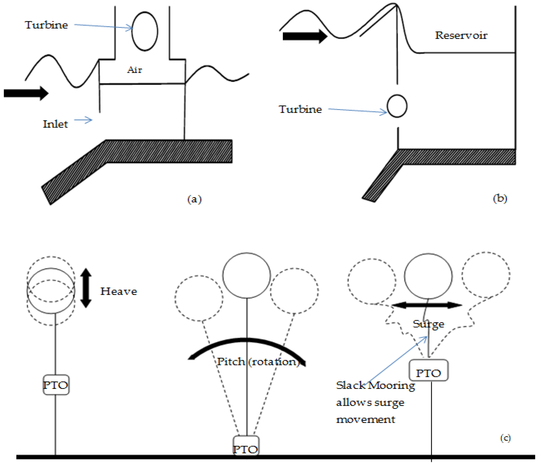
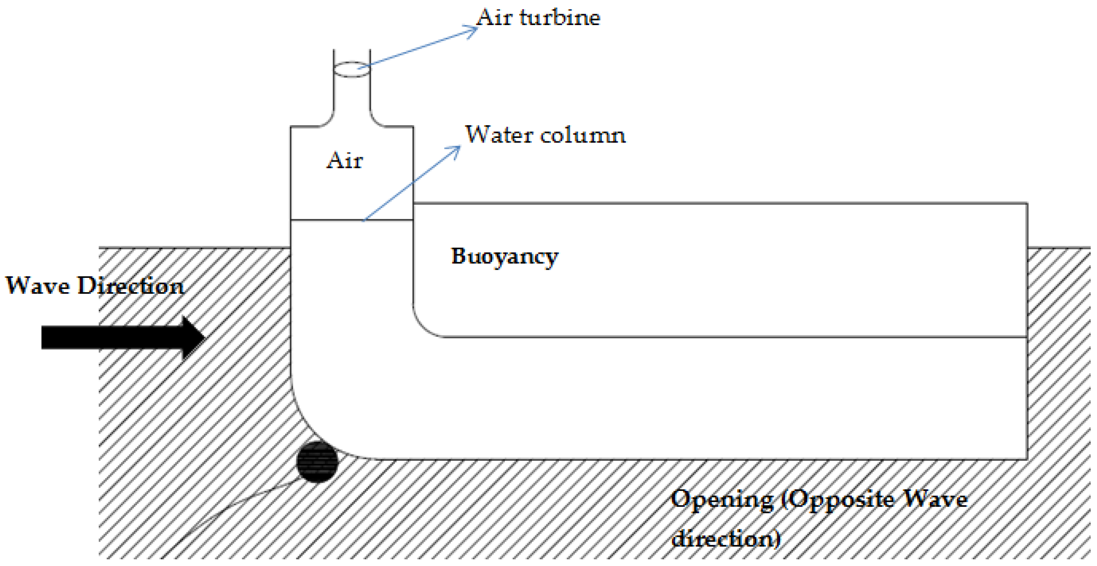
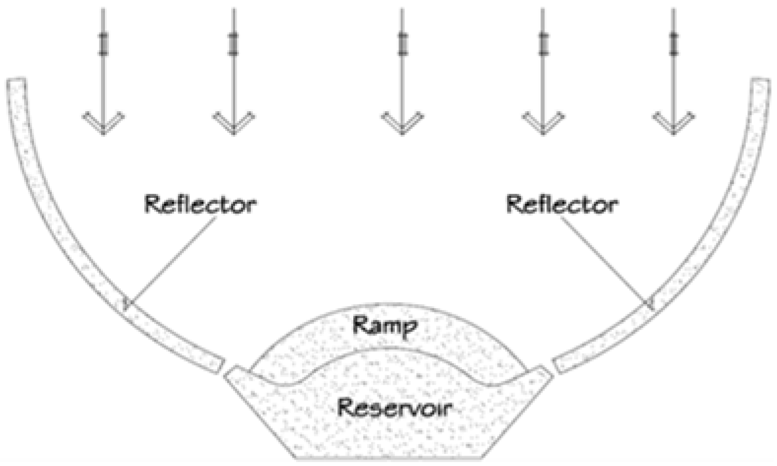
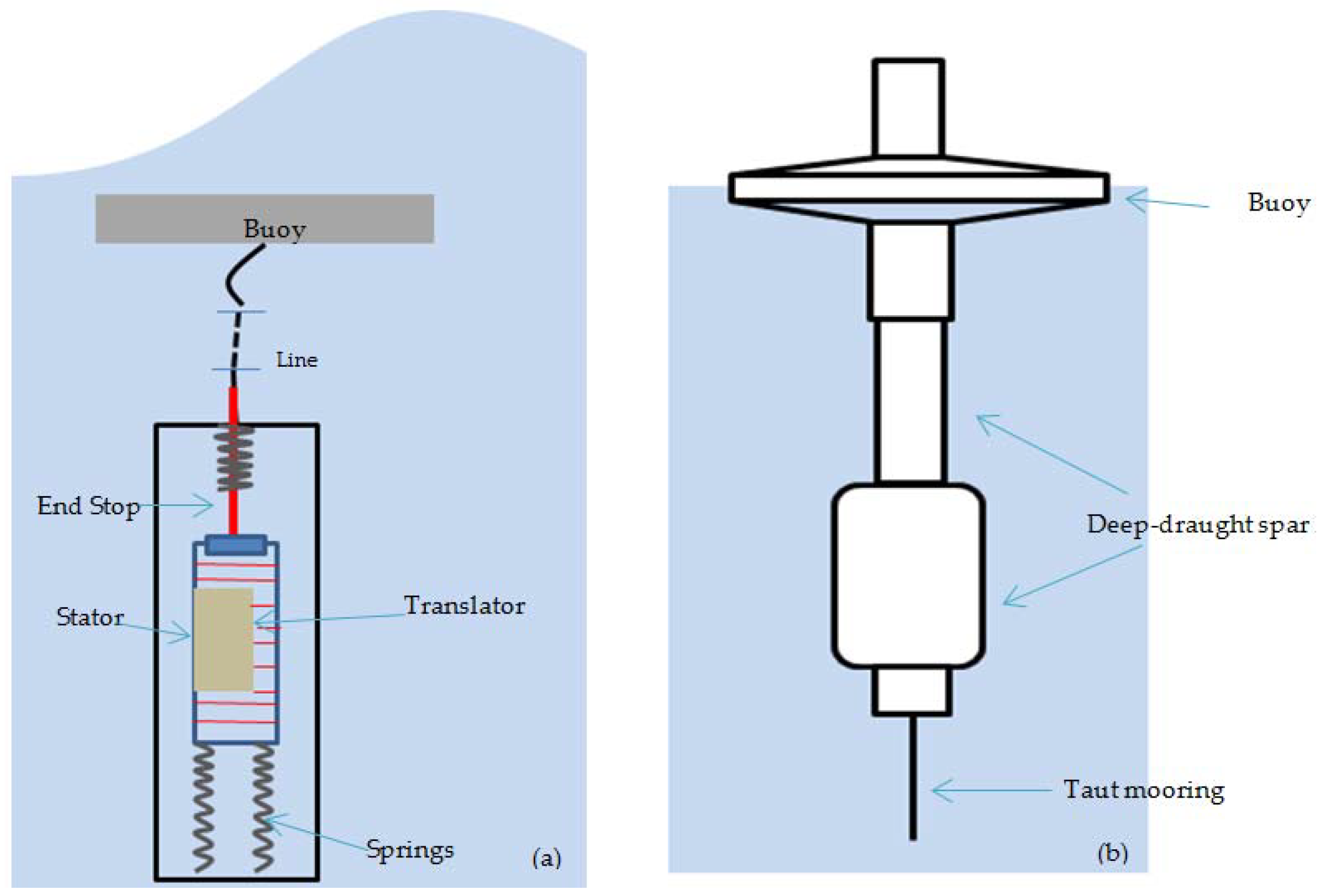
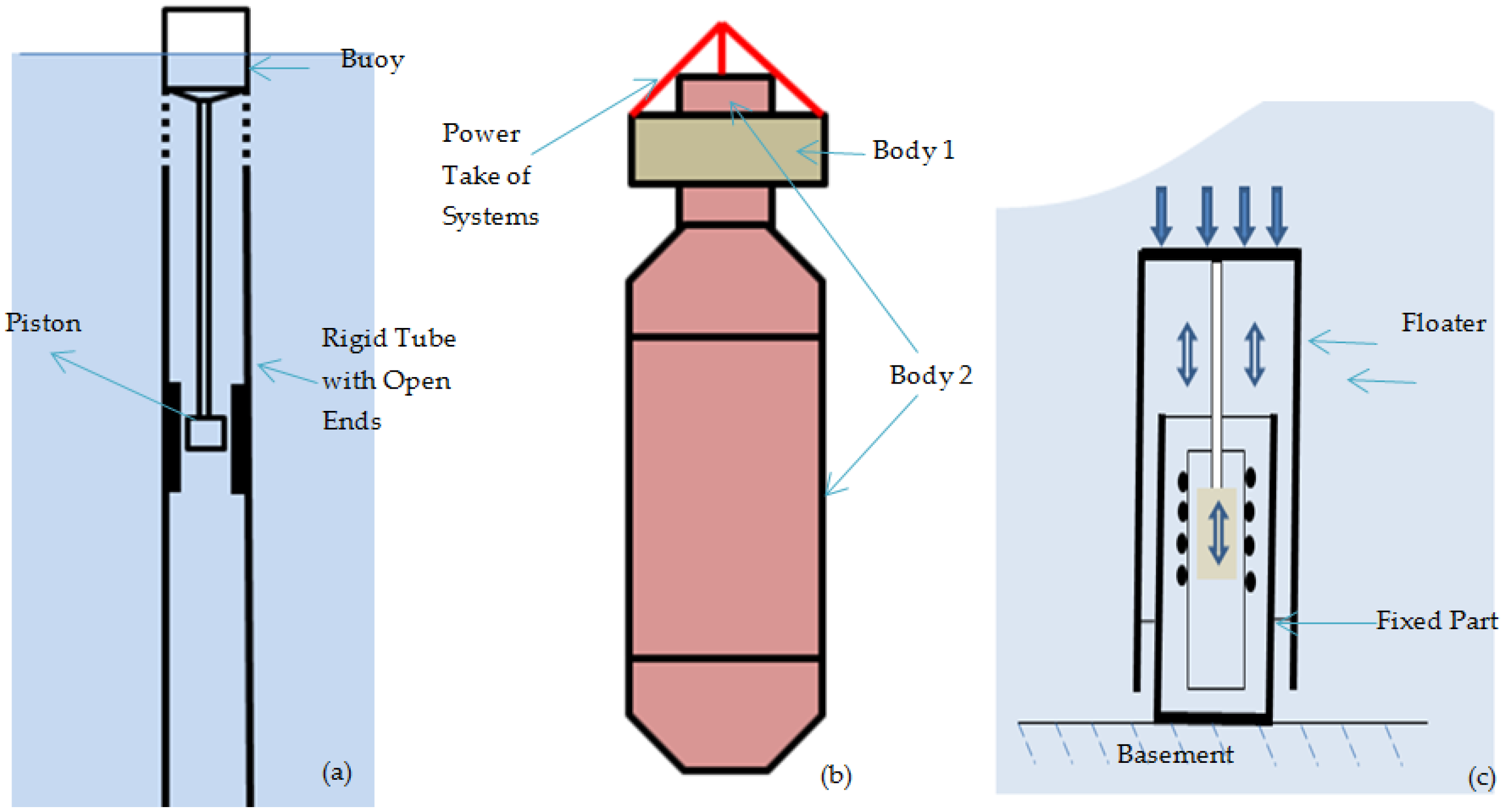
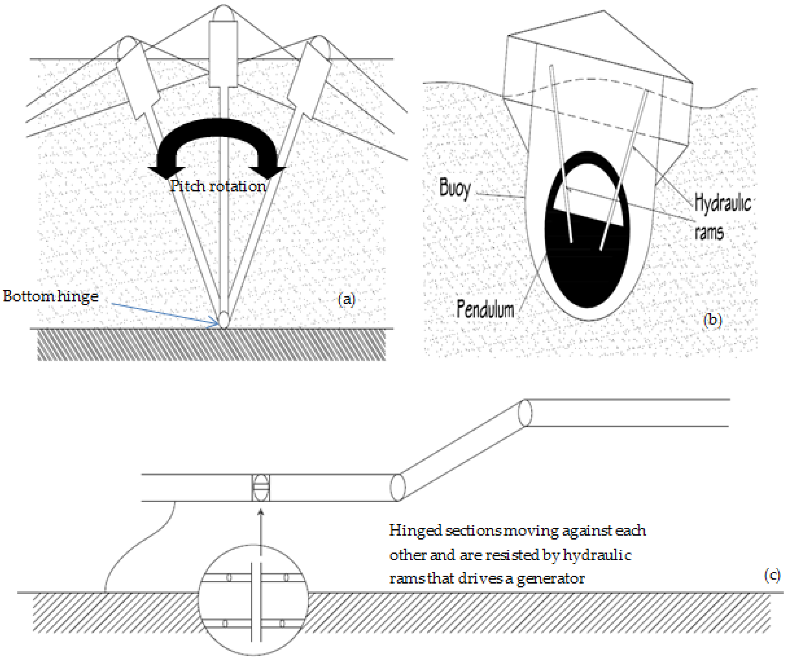
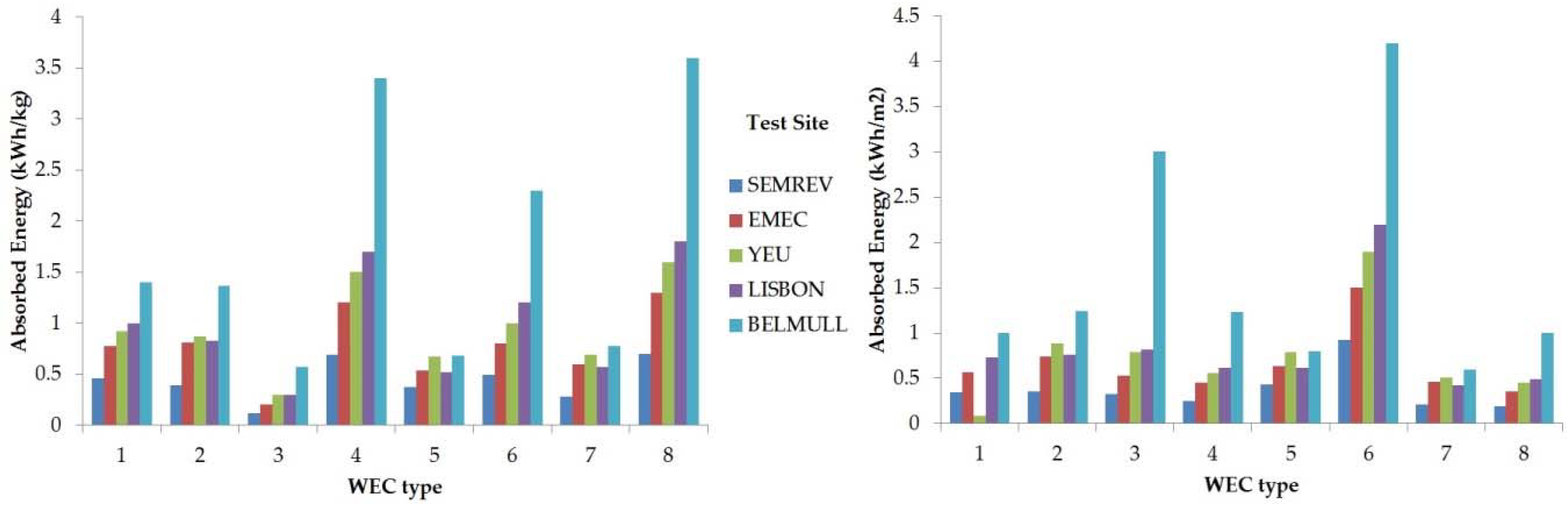
Table 1.
Wave Energy Converters Installations (kW) around the World [24].
Table 1.
Wave Energy Converters Installations (kW) around the World [24].
| Country | Planned | Installed | Operational | Total |
|---|---|---|---|---|
| Canada | 0 | 0 | 11 | 11 |
| New Zealand | 0 | 20 | 0 | 20 |
| Denmark | 39 | 12 | 1 | 52 |
| Italy | 0 | 150 | 0 | 150 |
| Mexico | 200 | 0 | 0 | 200 |
| Ghana | 0 | 0 | 450 | 450 |
| Spain | 0 | 230 | 296 | 526 |
| Korea | 0 | 0 | 665 | 665 |
| China | 0 | 400 | 300 | 700 |
| Portugal | 350 | 0 | 400 | 750 |
| United States | 1335 | 500 | 30 | 1865 |
| Sweden | 0 | 0 | 3200 | 3200 |
| Ireland | 5000 | 0 | 0 | 5000 |
Table 2.
Theoretical Potential of Wave Energy Resource in Different Regions of the World [19].
Table 2.
Theoretical Potential of Wave Energy Resource in Different Regions of the World [19].
| Regions | Wave Energy Potential (TWh/y) |
|---|---|
| Mediterranean Sea and Atlantic Archipelagos (Azores, Cape Verde, Canaries) | 1300 |
| Central America | 1500 |
| Western and Northern Europe | 2800 |
| Africa | 3500 |
| North America and Greenland | 4000 |
| South America | 4600 |
| Australia, New Zealand and Pacific Islands | 5600 |
| Asia | 6200 |
| TOTAL | 29,500 |
Table 3.
Summary of Wave Energy Converters with Examples.
| Wave Energy Harvesting Method | Examples | ||
|---|---|---|---|
| Oscillating Water Column | Fixed Structure | Pico [76], LIMPET [77], Sakata [26], REWEC3 [78], Mutriku [79] | |
| Floating Structure | Mighty Whale [106] | ||
| Oscillating Bodies | Floating | Heave | IPS buoy [92], Wavebob [93], AquaBuoy [91] |
| Rotation | Pelamis [98], SEAREV [99] | ||
| Submerged | Heave | AWS [94] | |
| Rotation | Wave Roller [30], Oyster [100], The Mace [101] | ||
| Overtopping Devices | Fixed Structure | TAPCHAN [84], SSG [86] | |
| Floating Structure | Wave Dragon [85] | ||
Table 4.
Examples of some Wave Energy Converters with their Power Take-Off (PTO) Systems.
| WEC Name | WEC Type | PTO | Remarks |
|---|---|---|---|
| Pico [76] | Oscillating water column | Wells turbine | Horizontal axis turbine used |
| LIMPET [77] | Oscillating water column | Wells turbine | - |
| REWEC3 [78] | Oscillating water column | Wells turbine | Multi turbines with 136 chambers |
| Mutriku [79] | Oscillating water column | Wells turbine | Multi turbines with 16 chambers |
| Mighty Whale [106] | Oscillating water column | Wells turbine | - |
| Sakata [26] | Oscillating water column | Wells turbine | Two units installed in breakwater |
| IPS buoy [92] | Heaving body | Hydraulic oil system & linear generator | Tests performed using the two listed PTO systems |
| AquaBuoy [91] | Heaving system | Impulse turbine | - |
| Wavebob [93] | Heaving body | Hydraulic System | Biodegradable hydraulic fluid |
| SEAREV [99] | Pitching system | Hydraulic System | Hydraulic pumps connected to the pendulum wheel charged the high pressure accumulators, which discharged their energy into hydraulic engines to drive electric generators |
| Pelamis [98] | Pitching system | Hydraulic System | Hydraulic pumps utilized the bending motion (caused by the passing waves) inside the joints |
| Oyster [100] | Pitching/quasi surge system | Hydraulic System | Bottom mounted WEC with water-pump serving as PTO |
| Wave Dragon [85] | Overtopping device | - | Turbines were used to convert the low head of the water into mechanical energy |
| TAPCHAN [84] | Overtopping device | - | Low head turbines and conventional hydroelectric turbines of appropriate size |
© 2018 by the authors. Licensee MDPI, Basel, Switzerland. This article is an open access article distributed under the terms and conditions of the Creative Commons Attribution (CC BY) license (http://creativecommons.org/licenses/by/4.0/).
Share and Cite
MDPI and ACS Style
Aderinto, T.; Li, H. Ocean Wave Energy Converters: Status and Challenges. Energies 2018, 11, 1250. https://doi.org/10.3390/en11051250
AMA Style
Aderinto T, Li H. Ocean Wave Energy Converters: Status and Challenges. Energies. 2018; 11(5):1250. https://doi.org/10.3390/en11051250
Chicago/Turabian StyleAderinto, Tunde, and Hua Li. 2018. "Ocean Wave Energy Converters: Status and Challenges" Energies 11, no. 5: 1250. https://doi.org/10.3390/en11051250
Note that from the first issue of 2016, this journal uses article numbers instead of page numbers. See further details here.