LCL Filter Design with EMI Noise Consideration for Grid-Connected Inverter


1
College of Mechatronics and Control Engineering, Shenzhen University, Shenzhen 518060, China
2
Department of Vehicle Engineering, National Taipei University of Technology, No. 1, Section 3, Chung-Hsiao E. Road, Taipei 106, Taiwan
*
Author to whom correspondence should be addressed.
Energies 2018, 11(7), 1646; https://doi.org/10.3390/en11071646
Submission received: 25 May 2018
/
Revised: 15 June 2018
/
Accepted: 20 June 2018
/
Published: 25 June 2018
(This article belongs to the Special Issue Power Electronics in DC-Microgrid Systems)
Abstract
:The grid-injected current total harmonics distortion (THD) and electromagnetic interference (EMI) noise must be considered in a transformer-less grid-connected inverter for a more electric aircraft (MEA) system. This paper develops a procedure for the design of the magnetic components of the LCL filter used in harmonic control and EMI reduction of the silicon carbide (SiC) grid-connected inverter in the MEA. The LCL filter is designed with effective harmonic attenuation and a compact size. To meet the space constraint requirement, specific design attention is focused on a customized amorphous cored inductor, with a comprehensive study of the relationships of inductor winding with respect to EMI noise. Reduced THD and EMI are verified through experiments performed on a 30 kW, 230 V/400 Hz three-phase grid-connected inverter prototype with the LCL filter.
1. Introduction
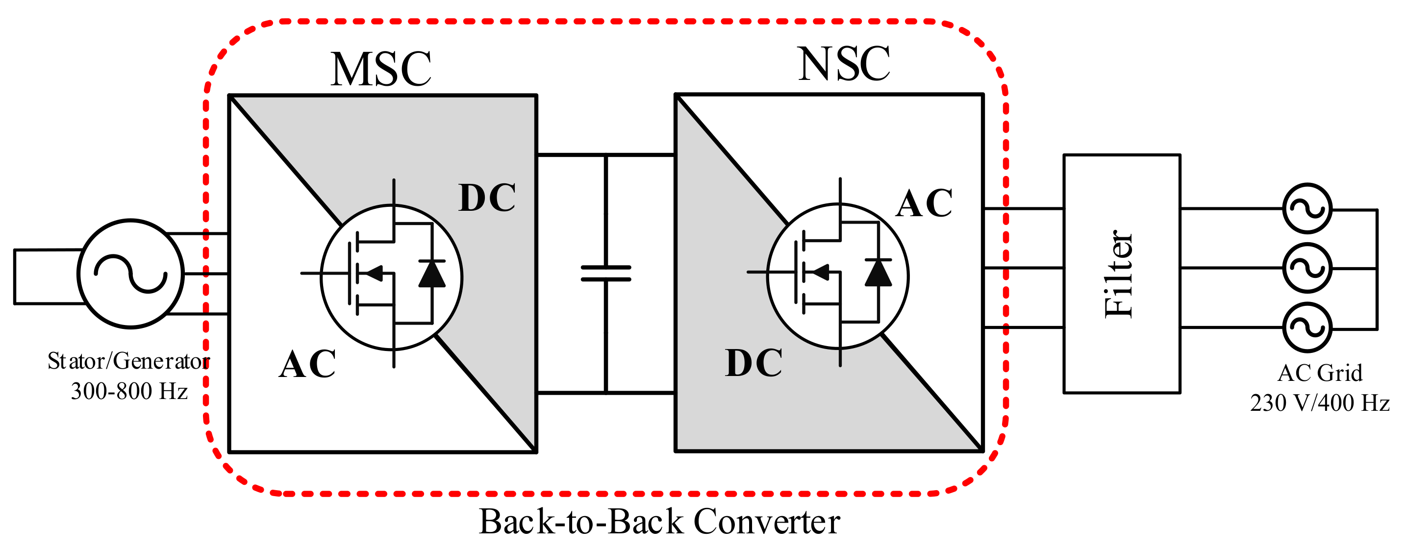
The concept of more electric aircraft (MEA) is based on the increasing use of electric power to replace the non-electric subsystems (pneumatic, mechanical, and hydraulic) in the traditional aircraft. The MEA concept provides significant improvements in reliability, maintenance cost, fuel consumption, and overall weight of the aircraft [1,2,3,4]. Because of the strict weight and space constraints, an electric starter/generator (ESG) is employed that acts as a motor to start the gas turbine engine and as a generator to convert the mechanical power to electrical power used to supply the onboard loads [5]. As in Figure 1, a back-to-back power converter that contains a machine-side converter (MSC) and a network-side converter (NSC) is used as the interface between the ESG and the power grid. As the passive components of the filter dominate the total weight of the power converter, the filter design has become one of the key technologies for MEA.
The LCL filter is widely used in the grid-connected inverter because of its harmonic attenuation performance and system stability. There are two inductors used, one located at the inverter side and the other located at the grid side. Compact and efficient magnetic components design in the power inverter results in minimization of its total size and weight; thus, magnetic material plays an important role in the grid-connected high power density inverter [6,7]. Winding technology [8,9,10], switching frequency [11], and core selection [12] are three important issues in the size reduction of magnetic components in the LCL filter.
Furthermore, current harmonic distortion of the grid-connected power inverter must be considered because of the power quality requirement in the power grid. In addition to the power quality of the power grid, another important issue is the conducted electromagnetic interference (EMI), which is mainly generated by the high frequency transistor switching and parasitic components in the noise conduction path [13,14,15]. Mostly, the EMI noise in the DC side of the inverter is suppressed to meet the EMI standard [16]. In Reference [17], the reduced EMI noise in the AC side of the inverter has been observed but the parasitic components in the LCL filter are not considered. In a grid-connected inverter, the differential mode (DM) EMI is dominant compared with the common mode (CM) EMI; thus, the LCL filter can be treated as an EMI filter [18] in the high frequency range if the self-resonant frequency in the filtering inductor is high enough. The resonant frequency is relatively dependent on the parasitic components in the inductor [19]. Thus, if total harmonics distortion (THD) and EMI can be reduced at the same time with one filter, the power density would be increased pronouncedly.
To address this problem, a higher order filter with a copper foil-wound inductor is used instead. Section 2 gives the procedure to determine the output LCL filter’s parameters. Section 3 presents the magnetic components design in the LCL filter. Section 4 evaluates the performance of the copper foil and copper wire inductors in EMI noise control. Section 5 presents the experiments. Finally, Section 6 concludes the paper.
2. LCL Filter Design Procedure
2.1. Components of the LCL Filter
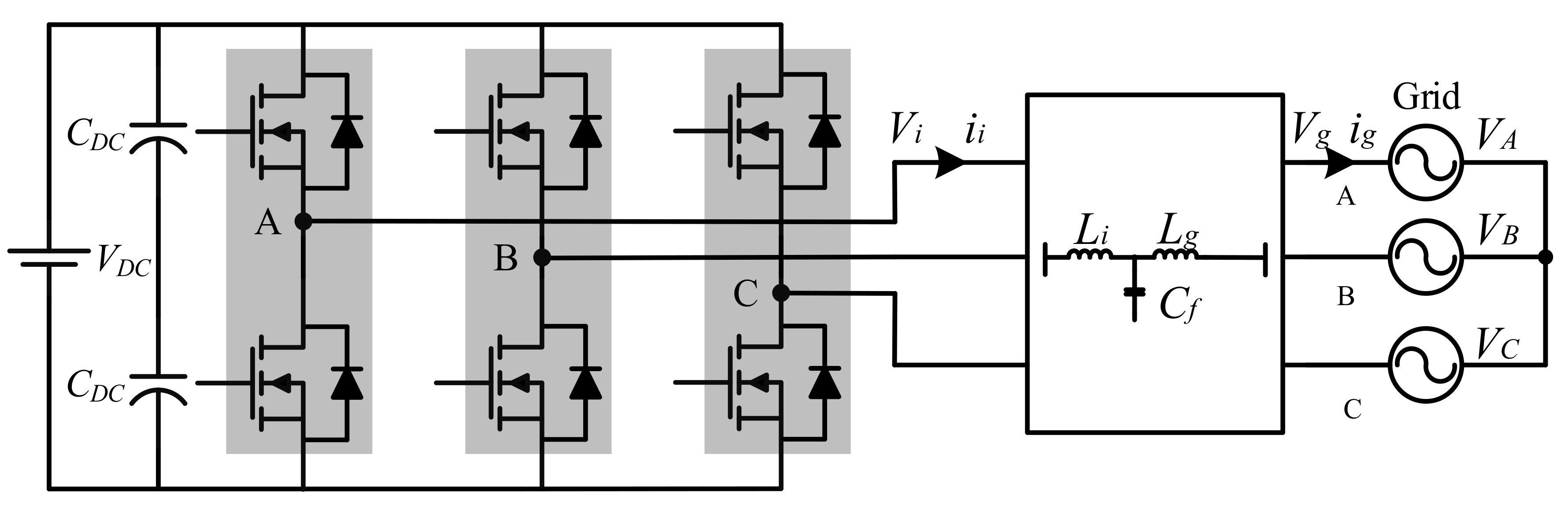
Figure 2 shows the LCL type grid-connected inverter system, which corresponds to the NSC shown in Figure 1. The output LCL filter is a component necessary to satisfy the harmonic limit requirement [20,21]. is the inverter side inductor, is the filtering capacitor, is the grid side inductor, is the inverter side voltage, and is the grid voltage.
The LCL filter is used to suppress the harmonics at the fundamental and multiples of the switching frequency . Compared with other filter topologies, the LCL topology [22] has low grid current distortion and reactive power production, good roll off of 60 dB/decade at high frequency and relatively low required switching frequency.
The bode plot of transfer function of the LCL filter, as given in Equation (1), exhibits 60 dB/decade attenuation above the resonant frequency, given by Equation (2). The resonant frequency should be in the range of to ensure the whole system remains stable.
In a two-level system, the maximum inverter side ripple current is given in Equation (3), where is the DC input voltage, and is the modulation index.
From Equation (3), one can see that the maximum current ripple occurred with the modulation factor = 0.5 given by Equation (4).
With a rated voltage of (phase to phase), an operating condition of power P, and a switching frequency in the grid-connected system, the base impedance is calculated by
Additionally, the base capacitance is
is the percentage of absorbed reactive power under the rated condition [23]. The filtering capacitor . The inverter side inductor can be selected by the maximum ripple current requirement, as shown in Equation (4). According to Equations (7) and (8), the minimum is calculated with Equation (9).
The grid side inductor is chosen according to attenuation ratio , as expressed in Equation (10). The LCL filter is expected to attenuate the grid side current in accordance with the IEEE Std 519, as shown in Table 1 [24]. The harmonic distortion and total demand distortion depends on the ratio of maximum short circuit current and maximum demand load current at the at the point of common coupling (PCC). In a grid-connected system, the ratio is usually smaller than 20 [25]. is the relationship between the two inductors. To increase the power density, the silicon carbide (SiC) power module is employed in the grid-connected inverter to ensure the switching frequency can be increased to 60 kHz or higher.
2.2. Simulation Results
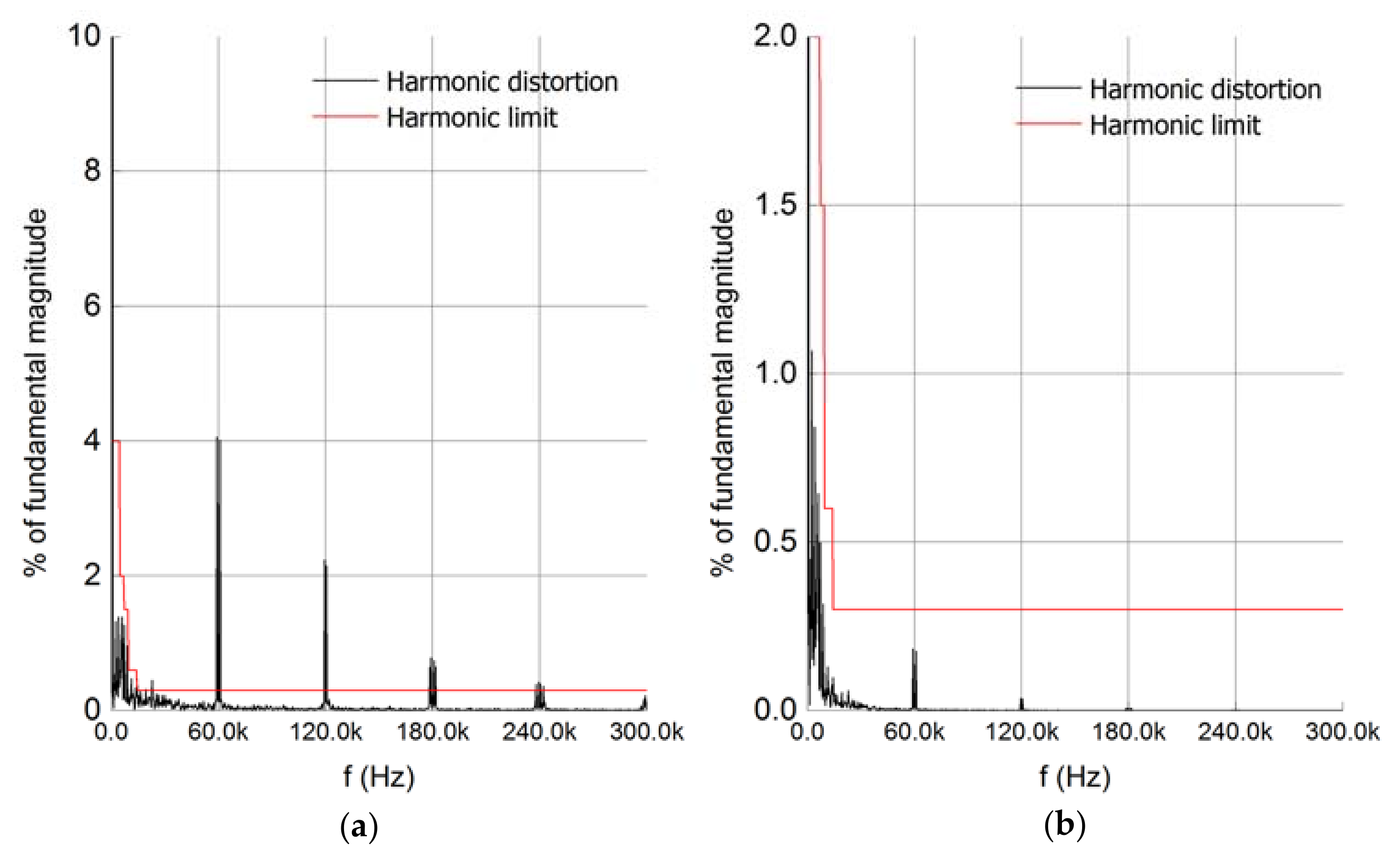
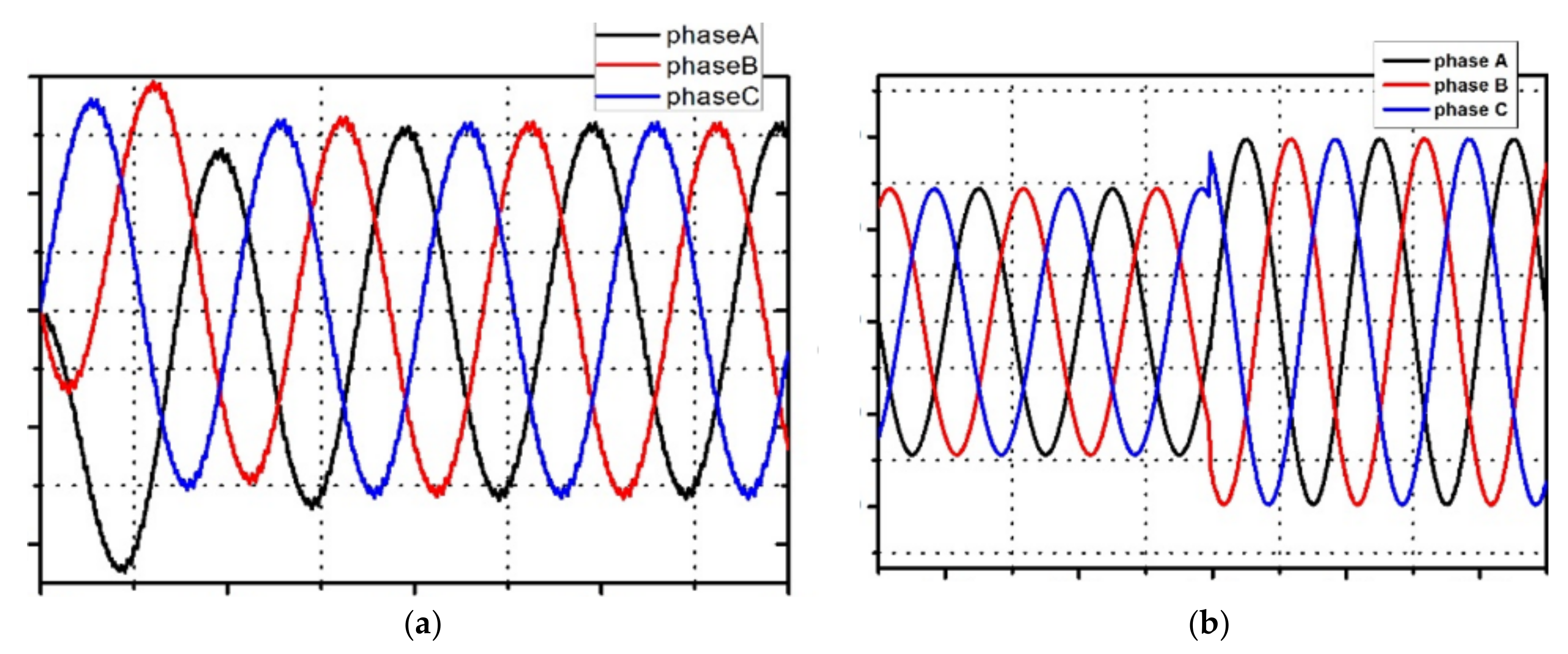
The simulation of LCL three-phase grid-connected inverter is carried out based on Matlab/Simulink to verify the system design procedure. The grid phase voltage is 220 V, the DC-link voltage is 750 V, the switching frequency is 60 kHz, and the rated power is 30 kW. Figure 3 shows the simulation currents and their THD analysis results. It reveals that the inverter side current’s total harmonic distortion is smaller than the harmonic limit. It can be found that the harmonics distortion is reduced from 6.47% to 2.26% by the LCL filter. The experimental setup can be designed according to the simulation parameters. Figure 4a shows the transient inverter side current at start time and Figure 4b shows dynamic response of grid-connected current. It can be seen that the system can be adjusted quickly and achieve stability, which shows that the system has good dynamic response performance.
3. Magnetic Material in the LCL Filter Design
3.1. Core Material Selection
To minimize the core loss and space, Table 2 shows some specifications for the different types of magnetic core materials in the power electronic converter design. is the maximum flux density, and , , and are the power loss parameters related to the switching frequency and the maximum flux density variation.
The nanocrystalline core has the lowest core loss, whereas the powder iron core has the largest core loss. The low core loss, high saturation flux density, wider operation frequency, and high operation temperature of the amorphous core allow for advanced power conditioning applications with high power.
The chosen amorphous EE magnetic core for the filtering inductor has an inductance L and carries a maximum current without saturating. is the effective cross area of the magnetic core, is the window area, MLT is the mean length per turn. The copper and core loss also should be considered and dissipated through the surface of the inductor winding.
In the three-phase EE core, the maximum flux density reduced to two-thirds via the increased flux density distribution. n is the number of turns, and is the gap length:
The celebrated general Steinmetz equation for core loss given in Equation (11) and the copper loss given in Equation (15) can be used to evaluate the temperature rise in the inductor.
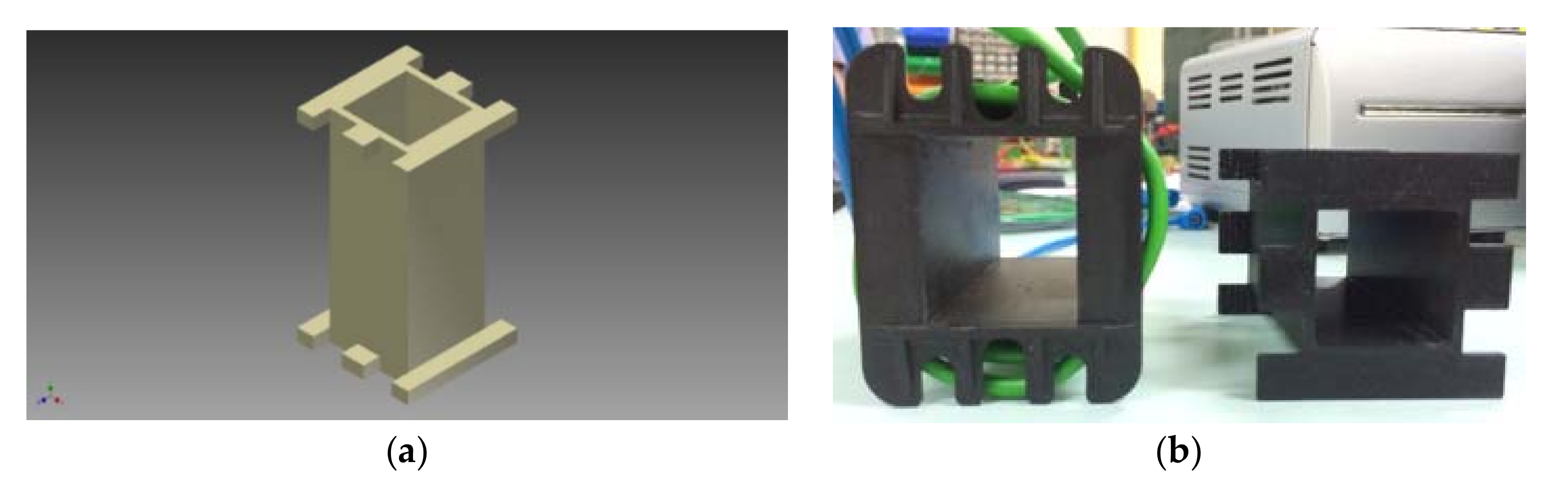
3.2. 3D Printing Technology for Bobbin Design
3D printing technology, as shown in Figure 5, is adopted for the bobbin fabrication to achieve the purpose of compactness. Figure 5b shows a comparison of the commercial and 3D printed bobbins; although the 3D printed bobbin is more expensive than the commercial bobbin, it can reduce the volume by up to 40%, leading to higher power density. The fabricated bobbin with a thickness of 2 mm and the acrylonitrile butadiene styrene (ABS) material is chosen for 3D printing.
4. Inductor Winding Design
4.1. Parasitic Components in the Two Types of Wound Inductors
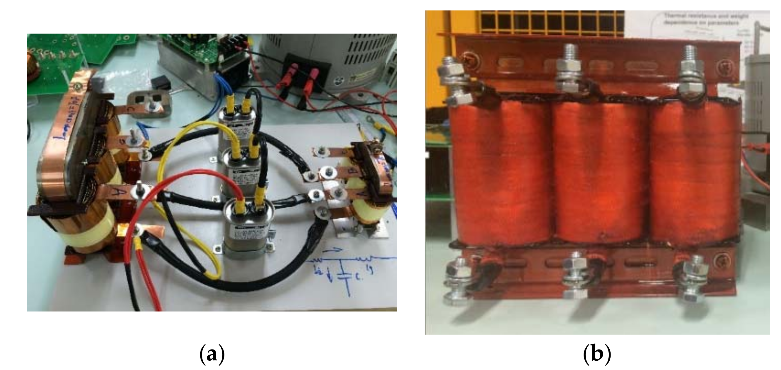
To reduce the parasitic components at higher frequency range, the conventional copper wire for inductor winding is replaced by copper foil with an EE amorphous core, as shown in Figure 6. Copper foil winding can help to reduce the inductor’s overall material cost by 15 to 20 percent. The copper foil winding can be used in high current applications because of its size reduction benefit. The size of the copper wire for high current is large and the window area in the magnetic core is limited. Using the copper foil for the winding is a better choice in the case of limited inductor space.
Table 3 shows the parameters of inductors and in the LCL filter, including core type, foil size, number of turns, and air gap. All the parameters are designed according to the inverter design specification. The amorphous core with low loss and high saturation flux density is chosen for the filtering inductors’ design.
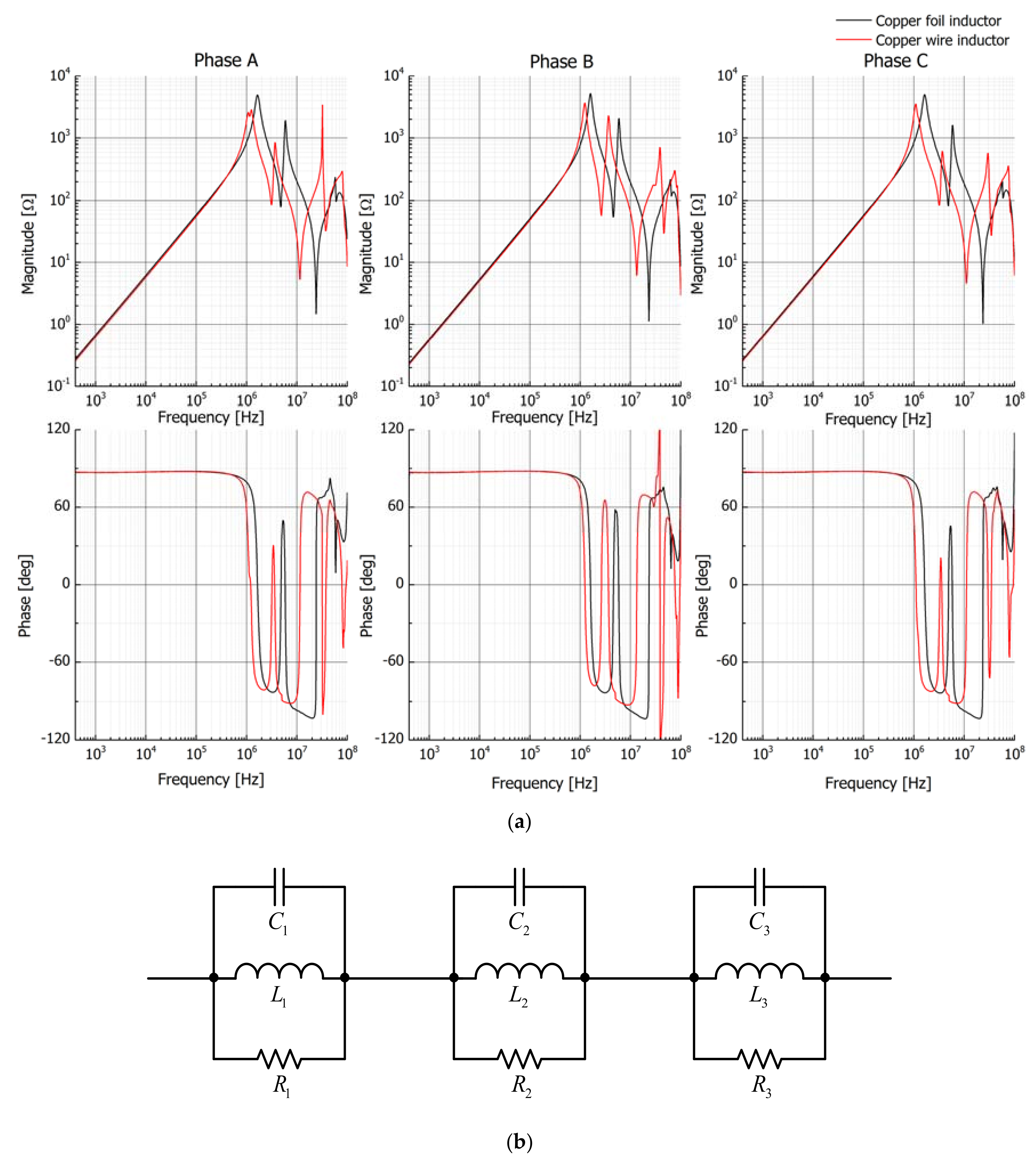
Figure 7a shows the impedance of the two types of inductors with different winding technology that is measured by a Hewlett Packard 4194A Impedance analyzer. The copper foil inductor is found to have higher resonant frequency than that of the copper wire inductor. The higher resonant frequency indicates that it has better noise attenuation for the conducted EMI noise in the range of 150 kHz to 30 MHz.
Figure 7a shows the high frequency model of the copper foil inductor, which is a second order equivalent circuit. Parasitic components of , , and can be calculated by the impedance values at , , and . Figure 7b reveals that the impedance of the whole equivalent circuit can be written as Equation (16).
The approximate values of , , , , , and can be estimated at the three frequencies , , and . The difference between the simulation and the measurement can be minimized via the least squares method, as shown in Equation (17), to improve the accuracy of the inductor parasitic components derivation.
Table 4 shows the equivalent circuit parameters in the two types of winding inductors. The value of in the copper foil inductor is found to be higher than that in the copper wire inductor. The larger high-frequency inductor can help to reduce the inductor of the EMI filter. More accurate circuit components in the filter can be used in the simulation model to predict the noise at low and high frequencies.
4.2. EMI Noise Model with LCL Filter Consideration
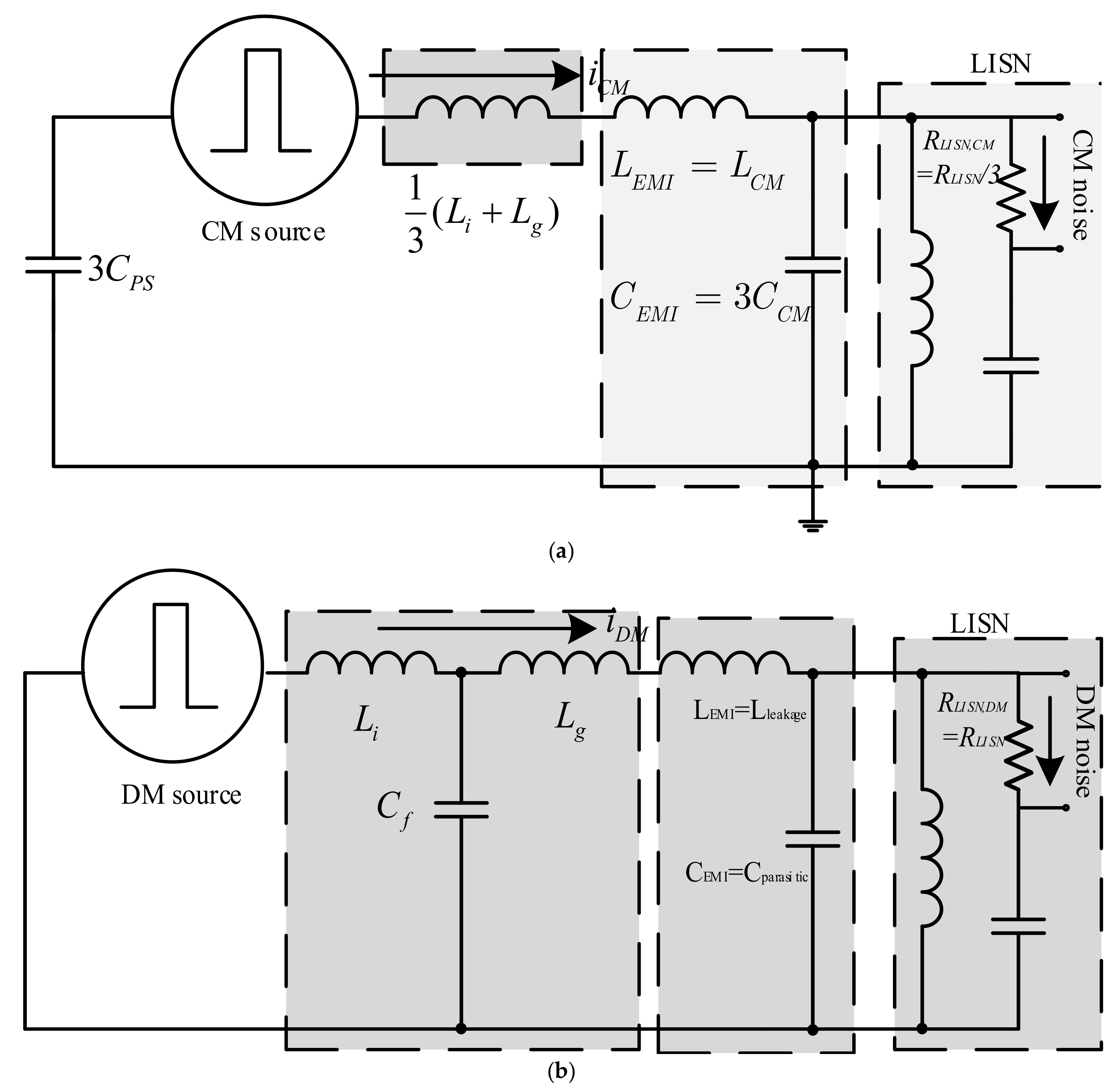
Figure 8 shows the common mode (CM) and differential mode (DM) EMI noise model with the LCL filter consideration; Equation (18) and Equation (19) are the CM and DM noise voltages, respectively. It can be found that the larger impedance of denotes the smaller noise voltage and reduced EMI filter requirement. Thus, the weight of the copper foil inductor is smaller than the copper wire inductor in the system requirement for the inverter. Compared to the copper wire inductor, the copper foil inductor has more efficient high-frequency noise attenuation ability and saves more space for the EMI filter design. According to the above analysis, the copper foil inductor will be designed and applied in the experiment to verify its THD and EMI noise attenuation effect.
5. Experiment Results
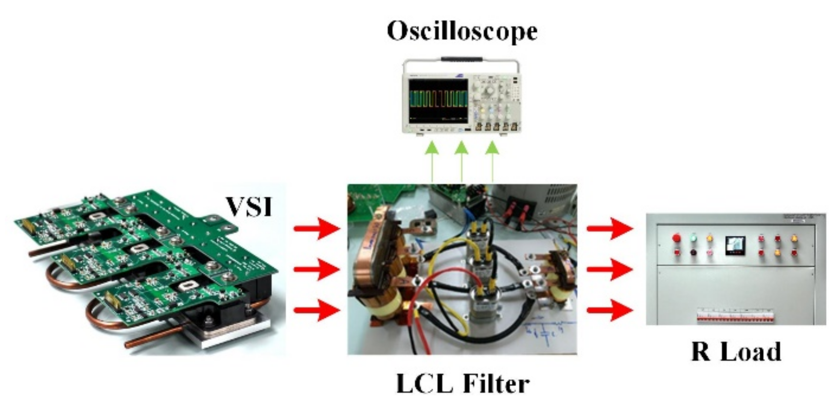
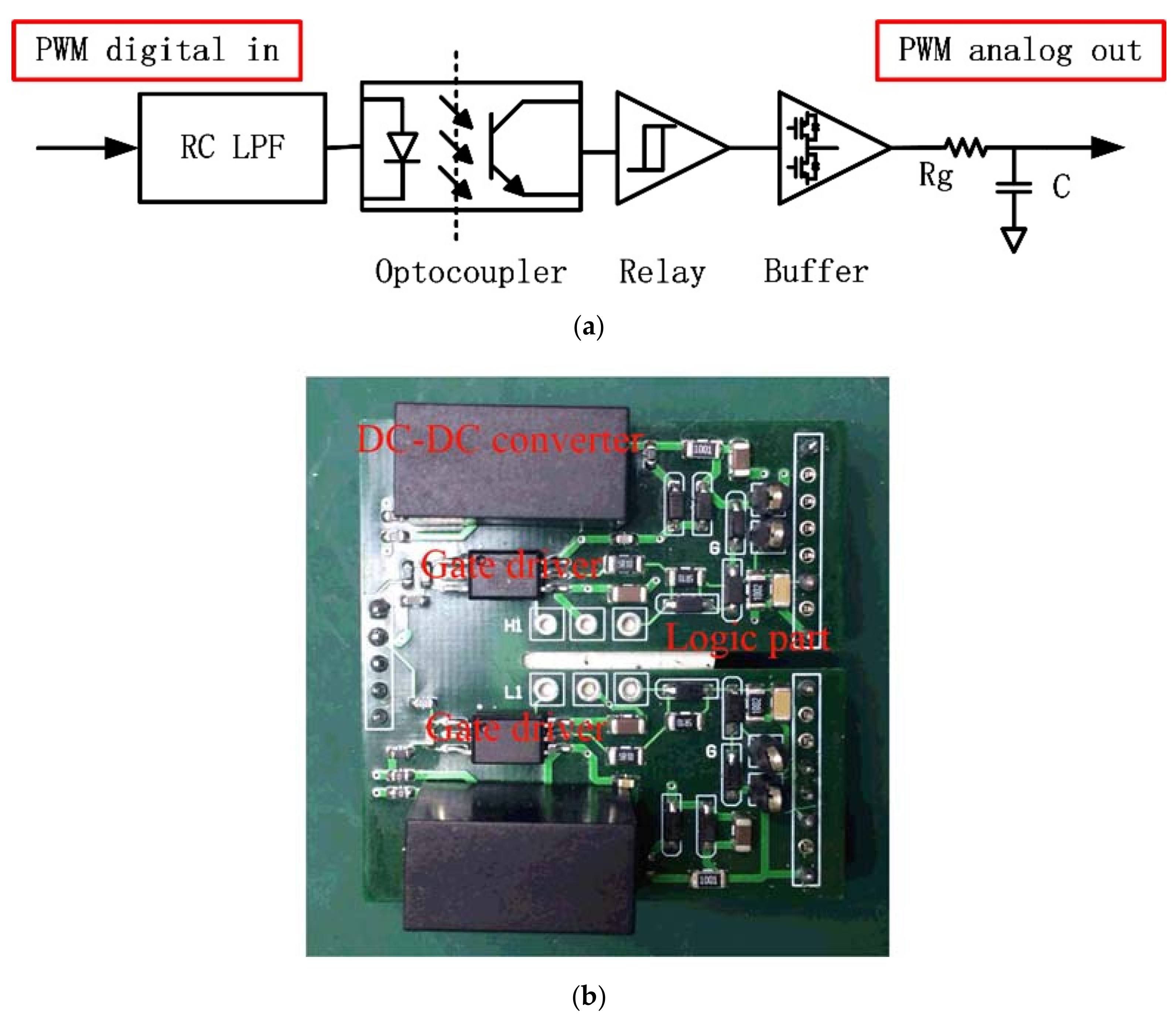
As shown in Figure 9, the LCL filter design was verified in a 30 kW, 750 V (DC) and 230 V/400 Hz two-level three-phase grid-connected inverter based on the early works. The SiC power module is employed to achieve a high switching frequency with the commercial product CAS100H12AM1 (1.2 kV, 100 A) from Wolfspeed. It achieves 97.9% energy conversion efficiency at an input power of 30 kW and switching frequency of 60 kHz. The filtering inductors are designed with amorphous core and are foil- or wire-wound for comparison. All the parameters in the copper foil- and copper wire-wound inductor are the same except for the winding material. The gate driver is a composite of five parts including the DC–DC converter module (G1212S-2W) which is shown in Figure 10. Integrated circuit (ACPL-P345) is chosen as the optocoupler which isolates the high working voltage and low driver voltage; the relay module which functions as a hysteresis comparator for threshold control; and the buffer is output gate current which increases the driving capability.
5.1. Copper Wire Inductor Analysis Results
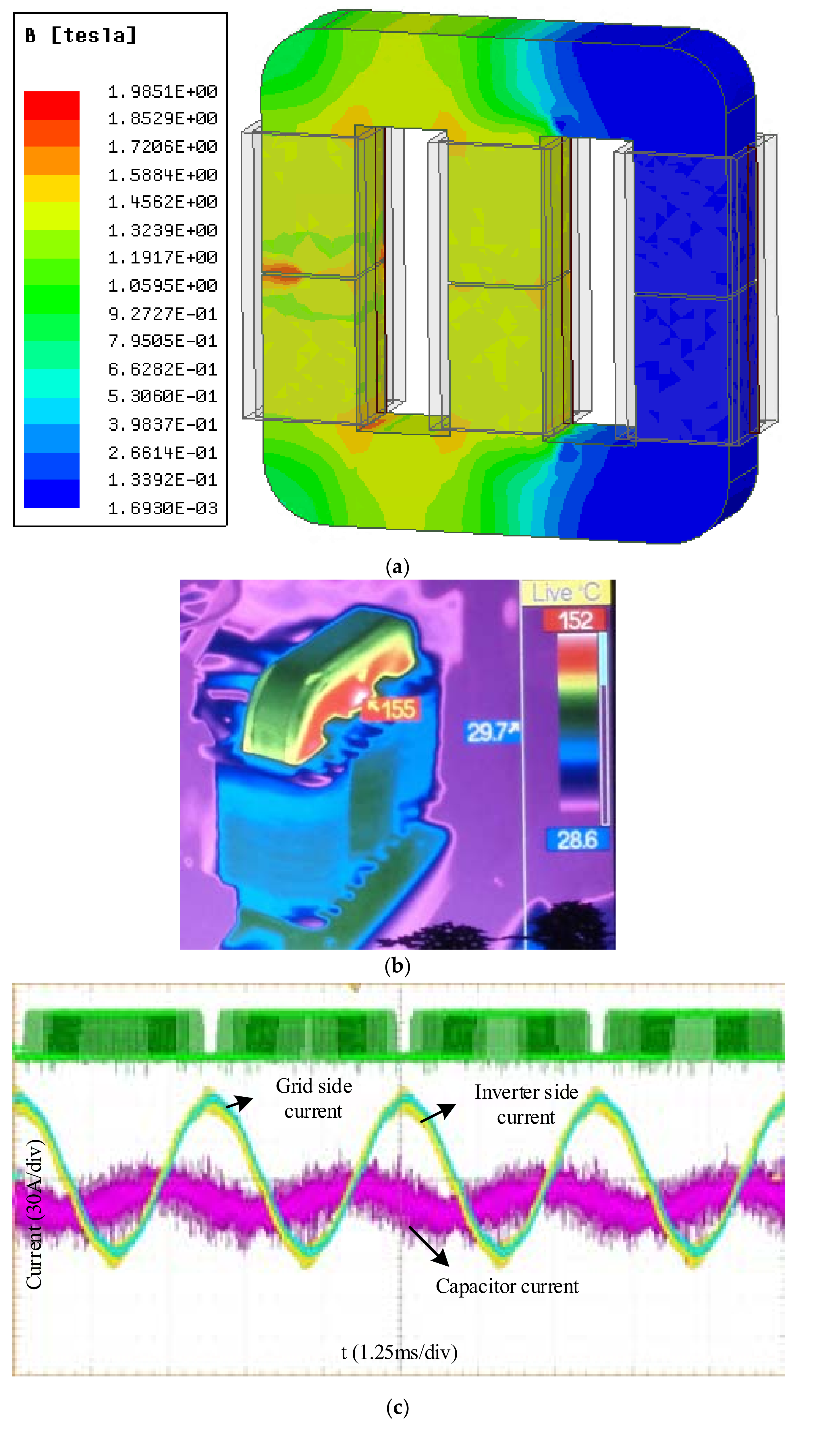
Figure 11a shows the simulated flux distribution at full load by finite element analysis (FEA) software, in which the maximum flux in the core is four-fifths of the saturation flux 1.56 T. Figure 11b shows the temperature distribution in the filtering inductor after one hour full load running; the maximum temperature is 155 °C, which is lower than its Curie Temperature of 399 °C.
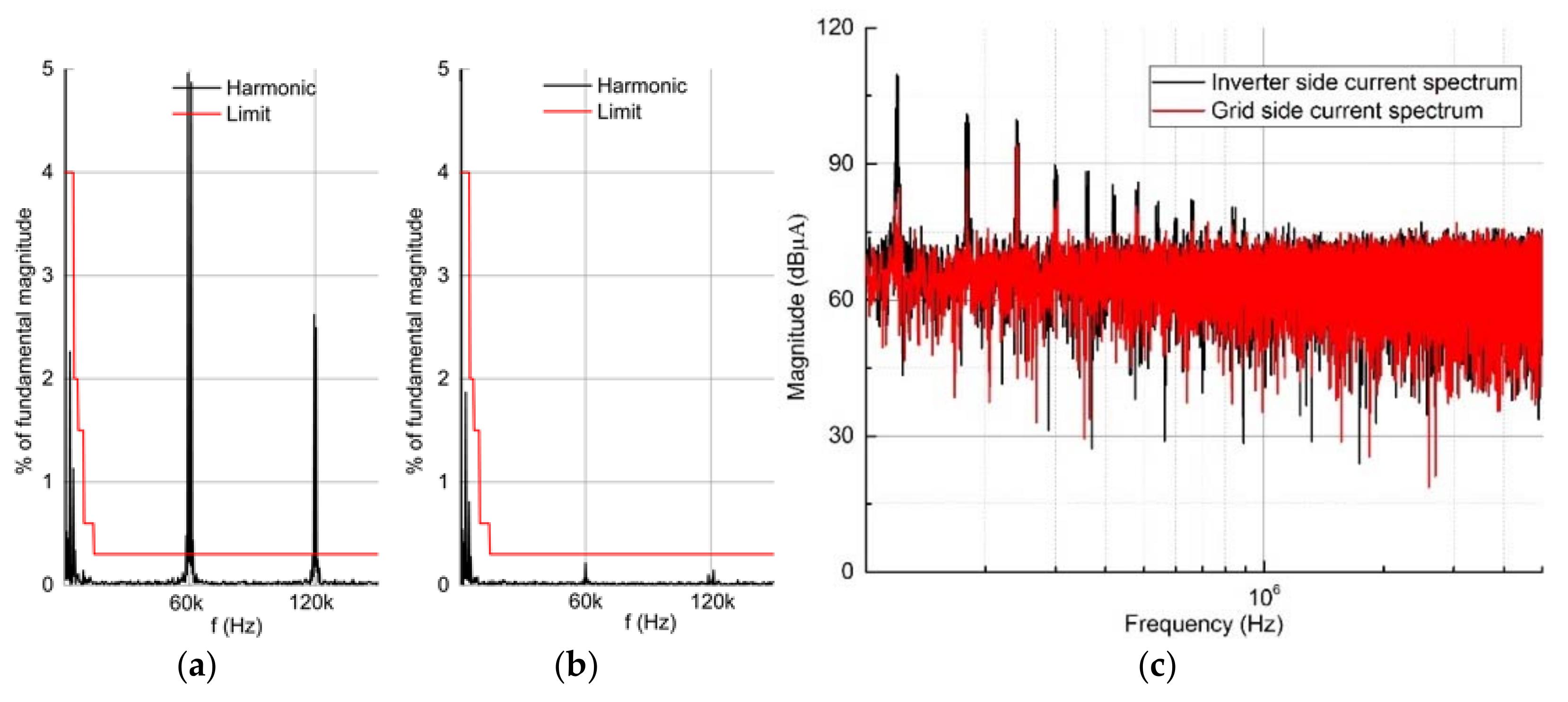
Figure 11c shows the experimental current in the inverter with foil-wound inductor. Figure 12a,b show a comparison of the current harmonic distortion, from which it can be found that the current distortion in the grid side is suppressed below the standard by the LCL filter. Figure 12c shows the high-frequency current spectrum, from which one can see that the spectrum is suppressed in the range of 150 kHz to 1 MHz, which is part of the EMI frequency range. The reduced EMI noise can lead to smaller EMI filter requirement.
5.2. Copper Foil Inductor Analysis Results
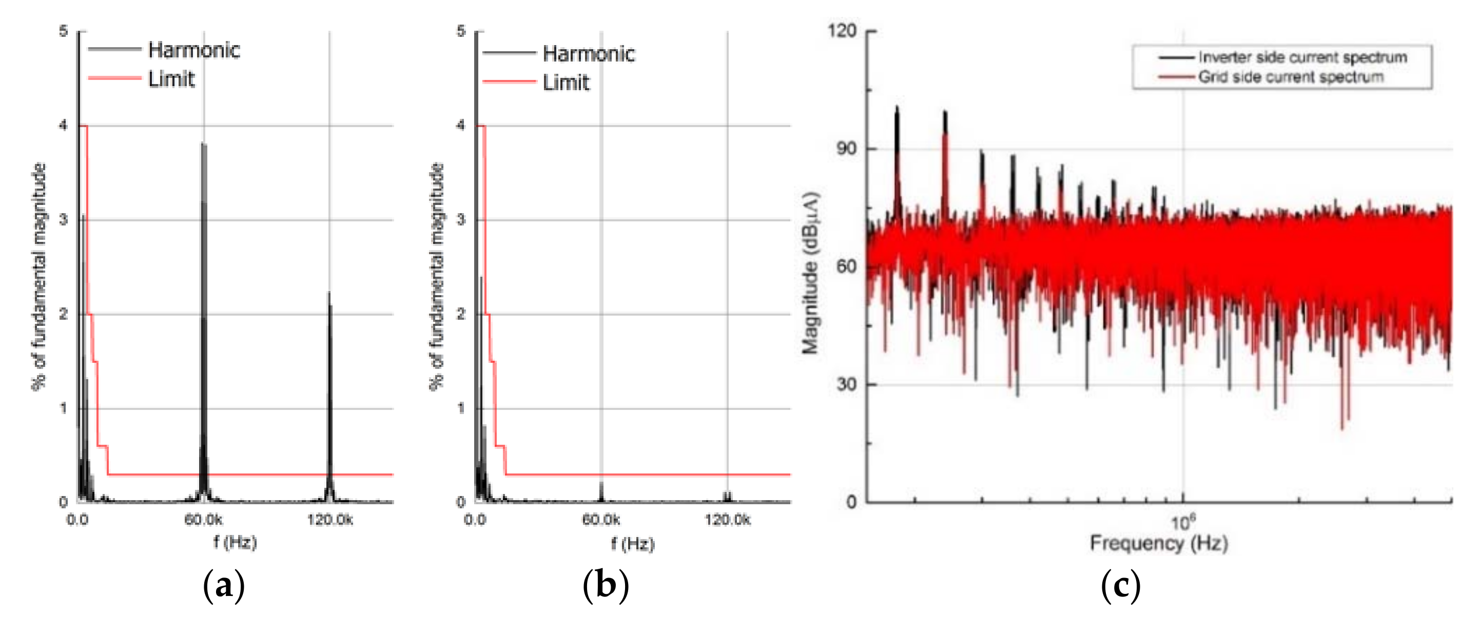
Figure 13a,b show the harmonic distortion of the measured current waveforms with the copper foil inductor in the LCL filter; one can see that the grid side current harmonic distortion is reduced below the standard. Figure 13c shows the reduced current spectrum in the frequency domain.
Figure 12c and Figure 13c reveal that the LCL filter is able to not only reduce the THD but also reduce the DM EMI noise at the higher frequency range. Lower resonant frequency can lead to greater noise attenuation performance, as derived from Figure 8, and Equations (18) and (19).
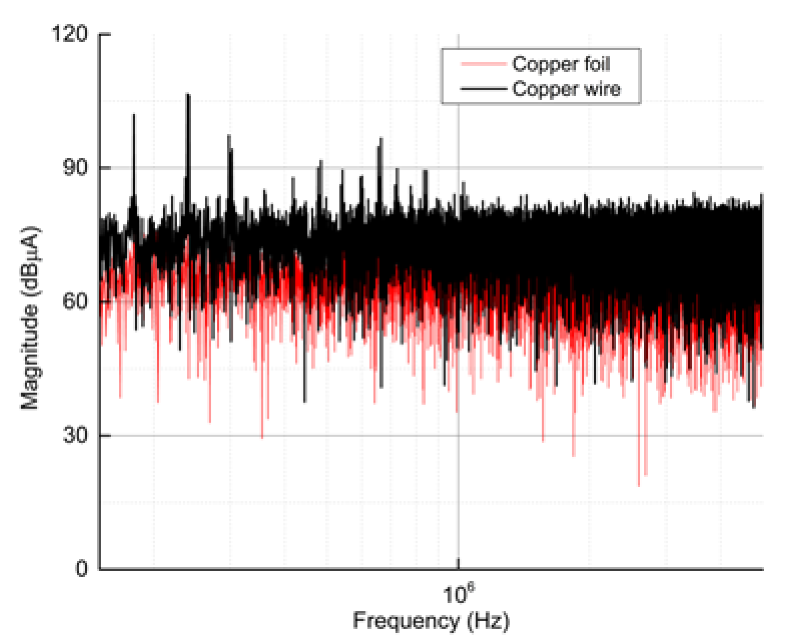
Figure 14 shows a comparison of the grid side current spectrum in the two types of LCL filters, one with copper wire inductor and the other with the copper foil inductor. The high-frequency current spectrum in the LCL filter with the copper foil-wound is smaller than that with the copper wire-wound. Thus, the foil-wound inductor is used in the high-power density inverter to achieve a smaller EMI filter requirement.
6. Conclusions
This paper proposed the LCL filter design in a grid-connected system using a foil-wound inductor, 3D printed components, and a SiC-based power converter. The experimental inverter and grid side currents’ spectrum were used to evaluate the noise attenuation comparison of the copper foil-wound and traditional copper wire-wound inductors in the LCL filter. Because of the higher resonant frequency, lower EMI noise, and reduced space requirement in the foil-wound inductor compared to the traditional approach, it is highly recommended for the high-power density inverter design.
Author Contributions
Y.L. conceived and designed the simulation and experiments; C.-M.L. analyzed the data.
Acknowledgments
The work was financially supported by the Foundations of Shenzhen Science and Technology Committee (JCYJ20170817100322198, JCYJ20160422165525693) and Natural Science Foundation of Guangdong—Doctor startup project (2017A030310317).
Conflicts of Interest
The authors declare no conflict of interest.
References
- Rosero, J.; Ortega, J.; Aldabas, E.; Romeral, L. Moving towards a more electric aircraft. IEEE Aerosp. Electron. Syst. Mag. 2007, 22, 3–9. [Google Scholar] [CrossRef] [Green Version]
- Sinnett, M. 787 No-bleed systems: Saving fuel and enhancing operational efficiencies. Aero Quart. 2007, 18, 6–11. [Google Scholar]
- Sarlioglu, B.; Morris, C.T. More electric aircraft: Review, challenges, and opportunities for commercial transport aircraft. IEEE Trans. Transp. Electr. 2015, 1, 54–64. [Google Scholar] [CrossRef]
- Cao, W.; Mecrow, B.C.; Atkinson, G.J.; Bennett, J.W.; Atkinson, D.J. Overview of electric motor technologies used for more electric aircraft (MEA). IEEE Trans. Ind. Electron. 2012, 59, 3523–3531. [Google Scholar]
- Bhangu, B.S.; Rajashekara, K. Electric starter generators: Their integration into gas turbine engines. IEEE Ind. Appl. Mag. 2014, 20, 14–22. [Google Scholar] [CrossRef]
- Donghua, P.; Xinbo, R.; Chenlei, B.; Weiwei, L.; Xuehua, W. Magnetic Integration of the LCL Filter in Grid-Connected Inverters. IEEE Trans. Power Electron. 2014, 29, 1573–1578. [Google Scholar] [CrossRef]
- Zhang, X. Passive Component Weight Reduction for Three Phase Power Converters; Virginia Polytechnic Institute and State University: Blacksburg, VA, USA, 2014. [Google Scholar]
- Wang, S.; Lee, F.C.; Van Wyk, J.D. Design of inductor winding capacitance cancellation for EMI suppression. IEEE Trans. Power Electron. 2006, 21, 1825–1832. [Google Scholar] [CrossRef]
- Stadler, A.; Huber, R.; Stolzke, T.; Gulden, C. Analytical calculation of copper losses in litz-wire windings of gapped inductors. IEEE Trans. Magn. 2014, 50, 81–84. [Google Scholar] [CrossRef]
- Hamalainen, H.; Pyrhonen, J.; Nerg, J.; Talvitie, J. AC resistance factor of litz-wire windings used in low-voltage high-power generators. IEEE Trans. Ind. Electron. 2014, 61, 693–700. [Google Scholar] [CrossRef]
- Burkart, R.M.; Uemura, H.; Kolar, J.W. Optimal Inductor Design for 3-Phase Voltage-Source PWM Converters Considering Different Magnetic Materials and a Wide Switching Frequency Range. In Proceedings of the International Power Electronics Conference (IPEC-Hiroshima 2014-ECCE ASIA), Hiroshima, Japan, 18–21 May 2014; pp. 891–898. [Google Scholar]
- Fan, T.; Li, Q.; Wen, X. Development of a high power density motor made of amorphous alloy cores. IEEE Trans. Ind. Electron. 2014, 61, 4510–4518. [Google Scholar] [CrossRef]
- Ji, J.; Wu, W.; He, Y.; Lin, Z.; Blaabjerg, F.; Chung, H. A simple differential mode EMI suppressor for the LLCL-filter based single phase grid-tied transformerless inverter. IEEE Trans. Ind. Electron. 2014. [Google Scholar] [CrossRef]
- Cheng, W.; He, X.; Xu, S.; Sun, W. Analysis of common-mode electromagnetic interference noise in a flyback converter using a self-supply power control integrated circuit. IET Power Electron. 2015, 8, 1749–1757. [Google Scholar] [CrossRef]
- Yang, X.; Long, Z.; Wen, Y.; Huang, H.; Palmer, P.R. Investigation of the trade-off between switching losses and EMI generation in Gaussian S-shaping for high-power IGBT switching transients by active voltage control. IET Power Electron. 2016, 9, 1979–1984. [Google Scholar] [CrossRef]
- Bishnoi, H.; Mattavelli, P.; Burgos, R.P.; Boroyevich, D. EMI filter design of DC-fed motor-drives using behavioral EMI models. In Proceedings of the 17th European Conference on Power Electronics and Applications (EPE’15 ECCE-Europe), Geneva, Switzerland, 8–10 September 2015; pp. 1–10. [Google Scholar]
- Weimin, W.; Yunjie, S.; Zhe, L.; Yuanbin, H.; Min, H.; Blaabjerg, F.; Chung, H.S.h. A modified LLCL filter with the reduced conducted EMI noise. IEEE Trans. Power Electron. 2014, 29, 3393–3402. [Google Scholar] [CrossRef]
- Liserre, M.; Blaabjerg, F.; Hansen, S. Design and control of an LCL-filter-based three-phase active rectifier. IEEE Trans. Ind. Appl. 2005, 41, 1281–1291. [Google Scholar] [CrossRef]
- Yang, S.F.; Huang, T.H. Design of single-turn spiral inductors with embedding a strong-coupling LC resonator for interference suppression. IEEE Trans. Electromagn. Compat. 2017, 59, 919–926. [Google Scholar] [CrossRef]
- Zheng, X.; Xiao, L.; Lei, Y.; Wang, Z. Optimisation of LCL filter based on closed-loop total harmonic distortion calculation model of the grid-connected inverter. IET Power Electron. 2015, 8, 860–868. [Google Scholar] [CrossRef]
- Muhlethaler, J.; Schweizer, M.; Blattmann, R.; Kolar, J.W.; Ecklebe, A. Optimal design of LCL harmonic filters for three-phase PFC rectifiers. IEEE Trans. Power Electron. 2013, 28, 3114–3125. [Google Scholar] [CrossRef]
- Weimin, W.; Yunjie, S.; Zhe, L.; Tianhao, T.; Blaabjerg, F.; Chung, H.S.h. A new type LCL filter with in-series parallel resonant circuit for single-phase grid-tied inverter. IEEE Trans. Ind. Electron. 2014, 61, 4640–4644. [Google Scholar] [CrossRef]
- Patel, Y.; Pixler, D.; Nasiri, A. Analysis and design of TRAP and LCL filters for active switching converters. In Proceedings of the 2010 IEEE International Symposium on Industrial Electronics (ISIE), Bari, Italy, 4–7 July 2010; pp. 638–643. [Google Scholar]
- Langella, R.; Testa, A.; Alii, E. IEEE Recommended Practice and Requirements for Harmonic Control in Electric Power Systems; IEEE: Piscataway, NJ, USA, 2014. [Google Scholar]
- Jiao, Y.; Lee, F.C. LCL filter design and inductor current ripple analysis for a three-level NPC grid interface converter. IEEE Trans. Power Electron. 2015, 30, 4659–4668. [Google Scholar] [CrossRef]
Figure 1.
System diagram of the electric starter/generator in more electric aircraft. (MSC: machine-side converter; NSC: network-side converter).
Figure 1.
System diagram of the electric starter/generator in more electric aircraft. (MSC: machine-side converter; NSC: network-side converter).

Figure 2.
Grid-connected system.

Figure 3.
Current spectrum of the inverter and grid sides: (a) total harmonics distortion (THD) = 6.47%; (b) THD = 2.26%.
Figure 3.
Current spectrum of the inverter and grid sides: (a) total harmonics distortion (THD) = 6.47%; (b) THD = 2.26%.

Figure 4.
Transient output current: (a) transient grid side current at start time; (b) dynamic response of grid-connected current.
Figure 4.
Transient output current: (a) transient grid side current at start time; (b) dynamic response of grid-connected current.

Figure 5.
3D printing technology: (a) configuration for 3D printing; and (b) comparison of a commercial and a 3D printed bobbin.
Figure 5.
3D printing technology: (a) configuration for 3D printing; and (b) comparison of a commercial and a 3D printed bobbin.

Figure 6.
Inductor design in the LCL filter: (a) copper foil-wound, 4.5 kg; (b) copper wire-wound, 6.5 kg.
Figure 6.
Inductor design in the LCL filter: (a) copper foil-wound, 4.5 kg; (b) copper wire-wound, 6.5 kg.

Figure 7.
(a) Impedance of three phases in the two types of inductors; (b) high frequency equivalent circuit of the inductor.
Figure 7.
(a) Impedance of three phases in the two types of inductors; (b) high frequency equivalent circuit of the inductor.

Figure 8.
Electromagnetic interference (EMI) noise model: (a) equivalent common mode (CM) noise model and (b) equivalent differential mode (DM) noise model.
Figure 8.
Electromagnetic interference (EMI) noise model: (a) equivalent common mode (CM) noise model and (b) equivalent differential mode (DM) noise model.

Figure 9.
Experimental setup.

Figure 10.
(a) The schematic of gate driver; (b) The switch gate driver.

Figure 11.
(a) FEA analysis for flux distribution; (b) inductor temperature distribution; (c) currents of the inverter and grid sides.
Figure 11.
(a) FEA analysis for flux distribution; (b) inductor temperature distribution; (c) currents of the inverter and grid sides.

Figure 12.
Harmonic distortion of the measured current with the copper wire winding: (a) inverter side; (b) grid side; and (c) reduced current spectrum at the grid side.
Figure 12.
Harmonic distortion of the measured current with the copper wire winding: (a) inverter side; (b) grid side; and (c) reduced current spectrum at the grid side.

Figure 13.
Harmonic distortion of the measured current with the copper foil winding: (a) inverter side; (b) grid side; and (c) reduced current spectrum in grid side.
Figure 13.
Harmonic distortion of the measured current with the copper foil winding: (a) inverter side; (b) grid side; and (c) reduced current spectrum in grid side.

Figure 14.
Comparison of the high frequency current spectrum at the grid side.


Table 1.
Current distortion limits for systems rated 120 V through 69 kV. (THD: total harmonics distortion.).
Table 1.
Current distortion limits for systems rated 120 V through 69 kV. (THD: total harmonics distortion.).
| Maximum Harmonic Current Distortion in Percent of I1 | |
|---|---|
| 4.0% | |
| 2.0% | |
| 1.5% | |
| 0.6% | |
| 0.3% | |
| THD | 5% |
Table 2.
Magnetic core loss parameters.
| Material | Ferrite | Power Iron | Nanocrystalline | Amorphous |
|---|---|---|---|---|
| (T) | 0.49 | 0.6–1.3 | 1.56 | 1.2 |
| 16.9 | 1798 | 2.3 | 0.053 | |
| 1.25 | 1.02 | 1.32 | 1.81 | |
| 2.35 | 1.89 | 2.1 | 1.74 |
Table 3.
Inductor parameters.
| Parameters | Li | Lg |
|---|---|---|
| Core type | AFEC-90a | AFEC-48a |
| Foil size | ||
| n | 14 | 5 |
| 1 mm | 0.5 mm |
Table 4.
Equivalent circuit parameters in the copper foil inductor and the copper wire inductor.
| Parameters | Copper Foil | Copper Wire | ||
|---|---|---|---|---|
| Estimated | Improved | Estimated | Improved | |
| 90 | 84 | 90 | 82 | |
| 103 | 110 | 237 | 260 | |
| 4922 | 4922 | 3525 | 3525 | |
| 10.8 | 3.8 | 10.6 | 2 | |
| 67.3 | 190 | 180 | 1000 | |
| 1916 | 1916 | 626 | 626 | |
| 0.65 | 0.46 | 1.13 | 0.9 | |
| 11.9 | 22 | 0.25 | 30 | |
| 237 | 237 | 578 | 578 | |
© 2018 by the authors. Licensee MDPI, Basel, Switzerland. This article is an open access article distributed under the terms and conditions of the Creative Commons Attribution (CC BY) license (http://creativecommons.org/licenses/by/4.0/).
Share and Cite
MDPI and ACS Style
Liu, Y.; Lai, C.-M. LCL Filter Design with EMI Noise Consideration for Grid-Connected Inverter. Energies 2018, 11, 1646. https://doi.org/10.3390/en11071646
AMA Style
Liu Y, Lai C-M. LCL Filter Design with EMI Noise Consideration for Grid-Connected Inverter. Energies. 2018; 11(7):1646. https://doi.org/10.3390/en11071646
Chicago/Turabian StyleLiu, Yitao, and Ching-Ming Lai. 2018. "LCL Filter Design with EMI Noise Consideration for Grid-Connected Inverter" Energies 11, no. 7: 1646. https://doi.org/10.3390/en11071646
Note that from the first issue of 2016, this journal uses article numbers instead of page numbers. See further details here.