Improved Performance of Dye-Sensitized Solar Cells with TiO2 Nanoparticles/Zn-Doped TiO2 Hollow Fiber Photoanodes


Department of Mechanical Engineering, Universitas Sebelas Maret, Surakarta 57126, Indonesia
*
Author to whom correspondence should be addressed.
Energies 2018, 11(11), 2922; https://doi.org/10.3390/en11112922
Submission received: 1 October 2018
/
Revised: 22 October 2018
/
Accepted: 24 October 2018
/
Published: 26 October 2018
(This article belongs to the Section A: Sustainable Energy)
Abstract
:In this study, dye-sensitized solar cells (DSSCs) were fabricated using double-layer photoanodes consisting of TiO2 nanoparticles (NPs) and Zn-doped TiO2 hollow fibers (HFs). The TiO2 HFs were prepared by co-axial electrospinning and used as the light-scattering layer in the DSSC. The thickness variations of the TiO2 NP and Zn-doped TiO2 HF photoanode layers affect the performance of the DSSC, especially the short-circuit photocurrent density. The thickness of the TiO2 NP layer significantly affected the absorbance of photons and N719 dye molecules in the double-layer photoanode, while that of the Zn-doped TiO2 HF layer affected the scattering of light, as indicated by the low light transmittance in the photoanode. Conventional DSSCs consist of single-layer photoanodes, and exhibit relatively low efficiency, i.e., 1.293% and 0.89% for TiO2 NP and Zn-doped TiO2 HF, respectively. However, herein, the highest efficiency of the DSSC (3.122%) was achieved with a 15 μm NP-5 μm HF photoanode, for which the short-circuit photocurrent density, open-circuit photovoltage, and fill factor were 15.81 mA/cm2, 0.566 V, and 34.91%, respectively.

1. Introduction
Renewable energies such as wind, geothermal, ocean, hydro, biomass, and solar are promising energy resources for meeting the increasing energy demand in the world [1,2,3]. Sun is the largest source of external energy for our planet. Solar energy is non-toxic, clean, and abundant to satisfy the increasing global energy demand [1]. Solar energy can be directly converted into electrical energy by using solar cells. Third-generation photo-electrochemical solar cells have advantages such as simple processing, environment-friendliness, low cost, and hence find application in a wide range of fields, including dye-sensitized solar cells (DSSCs) [1,4,5,6,7]. DSSCs comprise a semiconductor material, electrolytes, transparent conductive oxide (TCO) substrates, counter electrode, and dye sensitizers [4,5,6,7,8,9,10]. The semiconductor material used as a photoanode has a very significant influence on the performance of the DSSC [11,12,13]. TiO2 is a typically used semiconductor material in DSSCs, and it can provide the highest efficiency among the others obtained with other semiconductor materials such as ZnO, NiO, SnO2, Nb2O5, WO3, Zn2SnO4, and SrTiO3 [14,15,16,17]. This advantage of TiO2 is attributed to its high photovoltaic performance in the visible region [14] and its ability to maximize the absorption of the dye sensitizer on the surface [18,19]. Extensive efforts have been undertaken to modify the morphology and structure of the semiconductor layer in the DSSC photoanode in order to achieve optimal performance [20]. Nanosized semiconductors have been widely used as a DSSC photoanode owing to their high absorption capability for dye sensitizers and the ability to effectively excite electrons [21,22,23].
Typically, small-sized semiconductors (<100 nm), in the form of nanoparticles (NPs) and nanopowders, are widely used as the photoanode in DSSCs [24]. Baglio et al. showed that DSSCs in which the photoanode comprised 10-μm-thick TiO2 nanopowder layers (particle diameter: 21 nm) yielded an efficiency of 1.44% efficiency. The open-circuit photovoltage (VOC), short-circuit photocurrent density (JSC), and fill factor (FF) were 0.69 V, 4.3 mW/cm2, and 50%, respectively [25]. Small-sized nanomaterials possess a large surface area for absorbing dye molecules. However, the high surface area of the photoanode reduces its ability to trap light owing to the large amount of grain boundaries, due to which most of the incoming light (incident light path) is lost [26,27]. On the other hand, large-size semiconductors (>100 nm) can capture a greater amount of the incoming light (incident light path) and scatter more photons in the photoanode; however, their ability to absorb dye molecules is low because of the reduced surface area [26,27,28,29,30].
One way to optimize the characteristics is to use a multilayer structure for the photoanode [31]. A multilayer photoanode comprising a dye-loading layer and a light-scattering layer improved the energy conversion efficiency of DSSCs [29,30,31,32,33,34]. Kim et al. showed that a multilayer stacked TiO2 nanoparticle/nanotube photoanode increased the short-circuit photocurrent density by approximately 12.6% [18]. Xie et al. showed that 500–800 nm TiO2 hollow microspheres had superior light scattering and electron diffusibility to enhance photovoltaic efficiency up to 28.4% [30]. Chava et al. also mentioned that the photoanode based on 150–200 nm TiO2 hollow nanoparticles for scattering layer increased photovoltaic efficiency from 6.08% to 7.58% [31]. The light-scattering layer in photoanode of DSSC provide a longer electron transfer path and higher charge-collection efficiency for improving photoconversion efficiency [18,27].
In a multilayer photoanode, TiO2 NPs are typically used as the dye-loading layer to optimize the absorption of dye molecules [15]. This is because an NP semiconductor has a larger surface area compared to materials with other morphologies [15,35]. On the contrary, semiconductors with one-dimensional nanostructures such as nanowires, nanotubes, nanorods, and nanofibers are suitable as a light scattering layer because of the larger particle size and electron transport capability [28,36]. In addition, modification of the nanofiber structure to a hollow fiber (HF) structure increases the scattering of light owing to the branched structure and larger surface area [37].
HF semiconductors can be fabricated by coaxially electrospinning capillaries [37,38], which produces a low-cost and simple system with excellent control of morphology [39]. Studies on the preparation of TiO2 HFs with excellent electrical properties and non-cracking continuous morphology have been conducted [37]. The addition of zinc to TiO2 HFs resulted in an increase in the inner and outer diameters of the TiO2 HFs. Furthermore, the current density of TiO2 HFs was improved because Zn doping increased the electron mobility. The previous study showed that Zn doping at 0.4% into TiO2 HF enabled the optimum performance of the DSSC owing to the synergetic effect of the anatase and rutile forms in the TiO2 semiconductors [37].
The aforementioned advantages of Zn-doped TiO2 HFs make them suitable for application as a light-scattering layer in DSSCs. However, there has been no systematic study on the use of TiO2 NPs and Zn-doped TiO2 HFs as the double-layer photoanode in DSSCs. In this study, the performance of a DSSC with a double-layer photoanode comprising TiO2 NPs as the dye-loading layer and Zn-doped TiO2 HFs as the light-scattering layer was investigated. The thickness of each layer was varied in order to analyze its effect on the performance of the DSSC.
2. Results and Discussion
2.1. Photoanode Characterization
Figure 1 shows the X-ray diffraction (XRD) pattern of the TiO2 NP and Zn-doped TiO2 HF. The peaks at 2θ = 25.4°, 37.9°, 48.1°, 53.8°, and 55.0° are in accordance with the (101), (004), (200), (105), and (211) crystallographic planes of TiO2. The size of the crystal in each semiconductor can be calculated by using the Scherrer equation, considering the highest peak, i.e., the (101) peak [37,40].
where D is the diameter of the crystallite TiO₂, λ is the wavelength of the X-ray (Cu Kα = 1.5406 Å), and k is a constant (~0.9). θ is the angle of diffraction, and B is the peak width based on the full width at half-maximum intensity. Equation (1) shows that the crystal size is inversely proportional to the peak width; hence the crystal size of the TiO2 NP (15.19 nm) is smaller than that of the Zn-doped TiO2 HF (16.48 nm). Figure 2a shows the morphology of the TiO2 NP. After sintering, the average grain diameter of the TiO2, NP becomes approximately 68.8 nm. The morphology of the Zn-doped TiO2 HF is shown in Figure 2b,c. The average size of the HF semiconductor is 285 nm (outer diameter) and 91 nm (inner diameter). This result suggests that Zn doping causes the diameter of TiO2 to increase [37], rendering it suitable as a light-scattering layer [26]. Figure 2d shows the cross-section image for the double-layer photoanode that consists of 15 µm TiO2 NP and 5 µm Zn-doped TiO2 HF layers.
Figure 3 is a plot of the optical absorption as a function of the photon energy for TiO2 NP and Zn-doped TiO2 HF. Tauc’s method for determining the band gap energy of a semiconductor is implemented using the following equation:
where α is the absorption coefficient, hv is the incident photon energy, c is a constant, and Eg is the electronic energy of the optical band gap. The photon energy is determined by h, Planck’s constant (6.626 × 10⁻³⁴ Js), and v, the frequency. The frequency can be calculated by the relation v = c/λ, where c is the speed of light (2.998 × 10⁸ m/s) and λ is the wavelength of light [22]. The band gap energy of the semiconductor can be determined by extrapolating the straight-line section in the (α.hv)1/r vs. hv curve (Figure 3). Anatase TiO2 is an indirect band gap type; hence, its r is constant, at 2. The results indicate that the band gap energies of TiO2 NP and Zn-doped TiO2 HF are 3.19 and 3.23 eV, respectively. The band gap energy of the HF structure in Zn-doped TiO2 was higher than that of the NP structure.
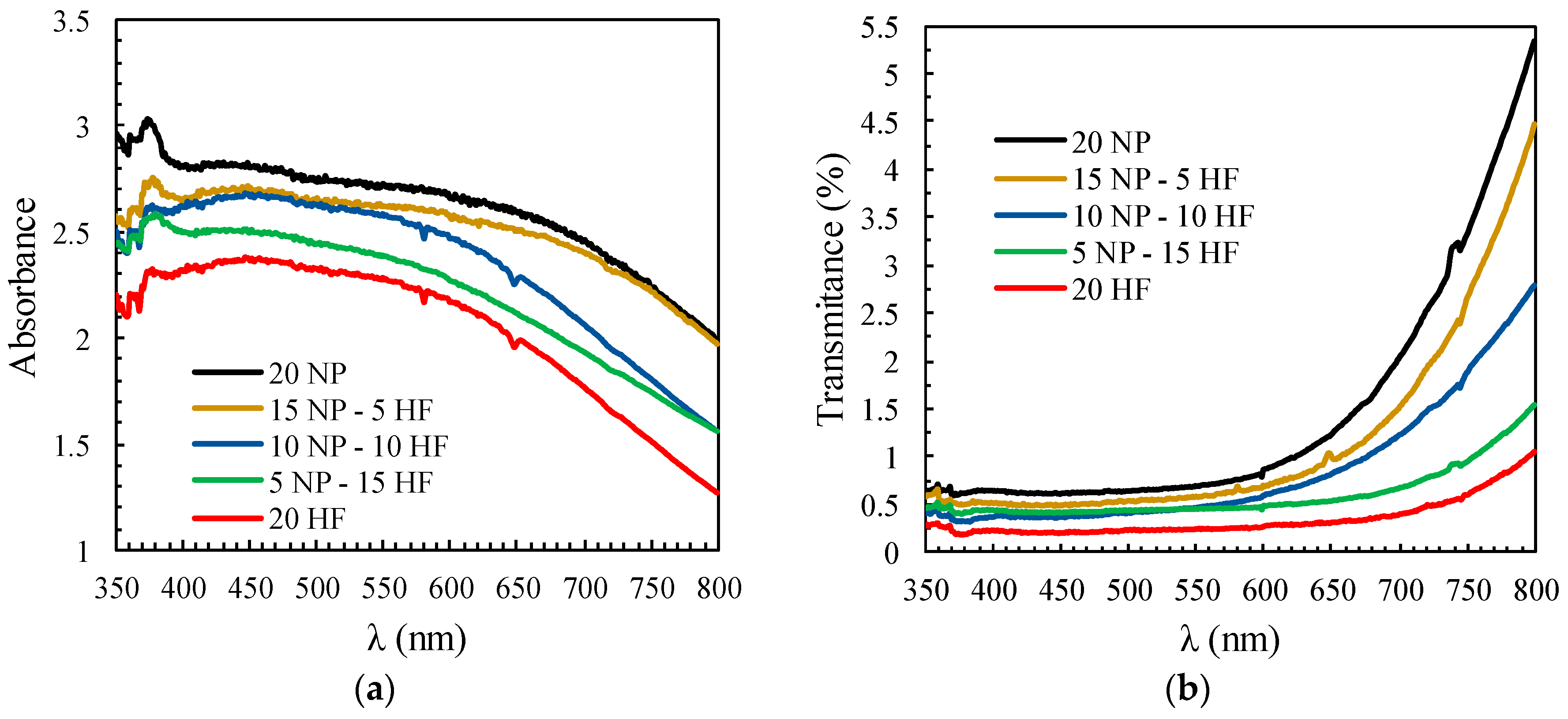
Figure 4 shows the absorption and transmittance of the TiO2 NP and Zn-doped TiO2 HF. Using Figure 4, the optical properties of the photoanode layers can be compared. The absorbance of pure TiO2 NP is higher than that of other photoanodes; hence, TiO2 NPs can absorb a large quantity of light entering the photoanode layer. However, the transmittance test results show that the TiO2 NPs also transmit a large amount of light out of the photoanode. The greater the content of TiO2 NPs in the photoanode, the higher is the light absorbance; however, the transmittance also increases. Conversely, a high content of Zn-doped TiO2 HF decreases the light transmittance as well as absorbance. Hence, the scattering of light in Zn-doped TiO2 HF is better than that in TiO2 NP, owing to the larger diameter and longer structure than TiO2 [28]. In this study, the double-layer structure was equally efficient in dye-loading by TiO2 NP and light scattering by Zn-doped TiO2 HF.
2.2. Performance of DSSCs
Table 1 shows the performance of the DSSCs in terms of the values of VOC, JSC, FF, and efficiency (η) for a typical dye-loading layer composition and thickness of the light-scattering layer in the DSSC photoanode. Figure 5 shows the performance and curves of the photocurrent density versus photovoltage (I-V) for each DSSC. Overall, changes in the photoanode composition of each DSSC do not change the VOC value, which is in the range of 0.55–0.61 V. This is partly because the total thickness of the photoanode in each DSSC is the same. Ito et al. showed that the thicker of photoanode gave the lower photovoltage in DSSC. Thus, the constant total thickness of photoanode in this work produce minor influence in VOC parameter [41]. DSSCs with a single-layer photoanode have a relatively low efficiency, i.e., 1.293% and 0.89% for 20 μm TiO2 NP and Zn-doped TiO2 HF, respectively. However, in this study, the highest DSSC efficiency of 3.122% was achieved by the composition 15 μm NP-5 μm HF for the double-layer photoanode. The DSSC efficiency using the composition 15 μm NP-5 μm HF was about 2.41 times higher than that of DSSCs with a conventional TiO2 NP single layer. The increase in the efficiency of the double-layer DSSC is primarily attributed to the increase in the photocurrent density of the DSSC, which is determined by how many photons are converted into the movement of electrons.
The morphology of TiO2 NP is small and uniform; hence, the NP layer exhibits maximum absorbance for the dye molecules, whereas the morphology of Zn-doped TiO2 HF is large and long, and hence, it supports optimal scattering [28]. The Zn-doped TiO2 HF with a diameter of 285 nm played as a scattering layer in the photoanode. It had superior light scattering capability for capturing a greater amount of incident light path. It produced more photons in the photoanode thus increased electron diffusibility. As a result, the DSSC with double layer of photonoda with a scattering layer leaded a higher photovoltaic conversion efficiency [30,31]. The previous study by Nath et al. showed that the use of light-scattering layers in the photoanode improved the incident photon-to-current conversion efficiency (IPCE) of the DSSC up to 32% [27]. By using TiO2 hollow microspheres with a diameter of 500–800 nm, and Xie et al. reported that light-scattering layers enhanced photovoltaic efficiency from 6.49 to 7.59% [30].
The DSSCs efficiencies in this work were range from 0.890 to 3.122% as shown in the Table 1. Compared with some previous studies [27,30,31], those efficiencies were relatively too low. It caused by the lower fill factor in the solar cell circuit. Fill factor is dominantly influenced by parasitic resistive losses that consists of series and shunt resistance [42]. The electrical resistance in the substrate and the contact resistance between semiconductor and FTO surface gave major influence in series resistance. Thus, it decreased both fill factor and photoconversion efficiency.
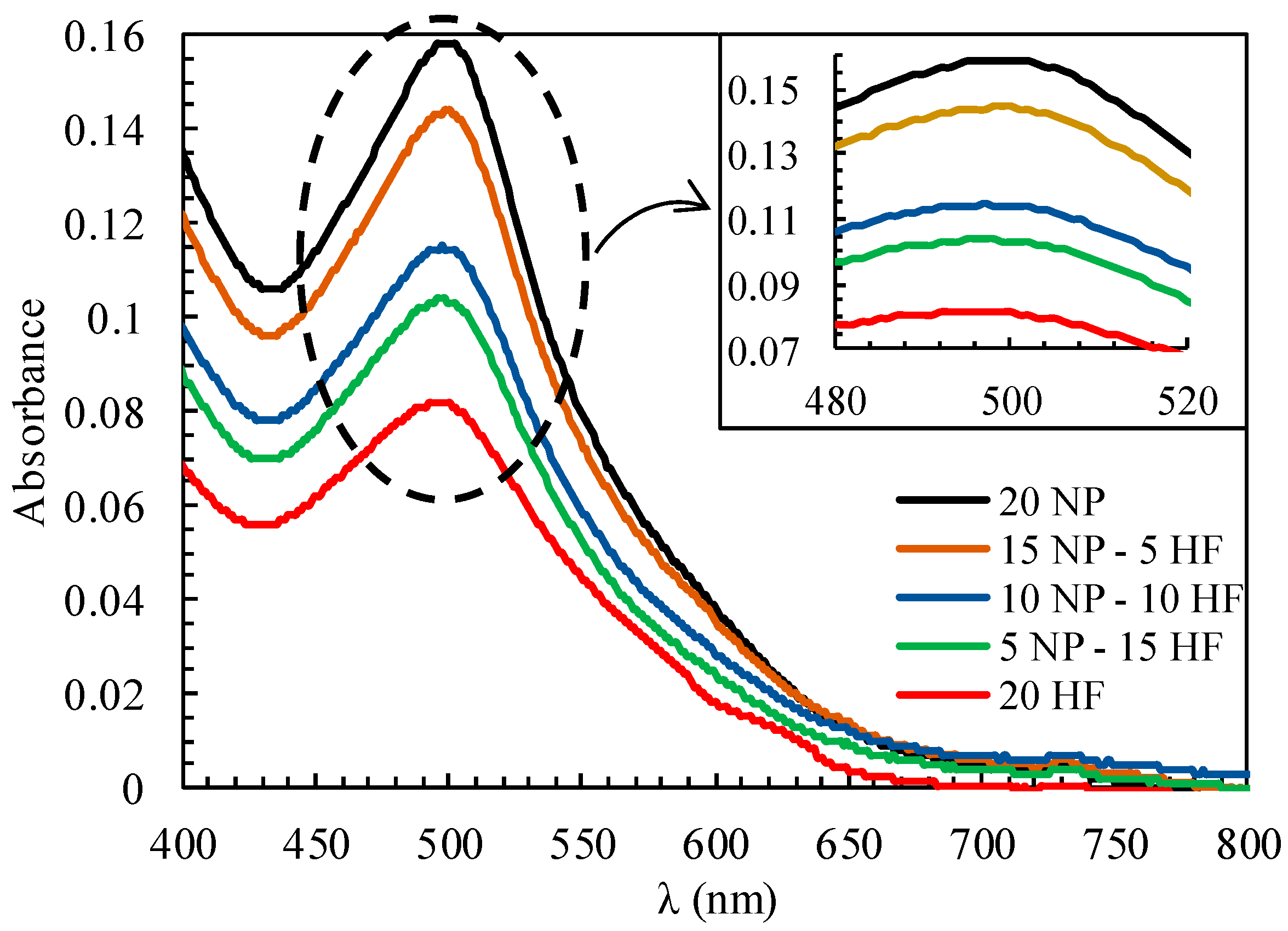
The amount of dye molecules that can be absorbed by the semiconductor (dye loading) was measured using the desorption method [43]. Semiconductors containing the absorbed N719 dye were soaked in 0.1 M NaOH with a distilled solvent for 10 min. Dye molecules that separated from the semiconductor dissolved in the NaOH solution. Further, UV-Vis absorption spectra were acquired to measure the concentration of the solution. Figure 6 shows the absorption spectra of a solution that contains the dye for each photoanode composition. The concentration of the dye loaded in the solution was calculated using the Beer-Lambert law.
A is the UV-Vis absorbance peak intensity, ε is the molar extinction coefficient of the N719 dye, c is the molecular dye concentration, and l is the path length of the light beam. The molar extinction coefficient of N719 for 14,100 M−1cm−1 at 515 nm was determined, and the values are listed in Table 1. Table 1 shows that the photoanode with the highest NP content (20 μm NP) had a high dye-loading capability (8.96 × 10⁻⁸ mol/cm2). However, with decreasing thickness of the NP layer, this capability also reduced owing to the decrease in the surface area available for the absorption of the dye molecules. NP structures that are smaller than the HF structure would provide a large surface area and high-density grain distribution.
3. Materials and Methods
3.1. Synthesis and Characteristics of TiO2 NPs and Zn-Doped TiO2 HF
The TiO2 NP (~ 21 nm particle size) substrate was provided by Sigma Aldrich (St. Louis, MO, USA) and used as received. The Zn-doped TiO2 HF was synthesized by co-axial electrospinning, as illustrated in Figure 7. A detailed description of the synthesis of Zn-doped TiO2 HF is provided in an earlier study [37]. The precursor solution used in co-axial electrospinning was prepared by mixing 0.37 g of titanium (IV) isopropoxide (TTIP, 99.9%, Sigma Aldrich-377 996), 1.13 g of polyvinylpyrrolidone (PVP, MW 40,000, Merck-PVP40, Kenilworth, NJ, USA), and 2 g of absolute ethanol (99.5%, 459 844 Sigma-Aldrich), following which it was stirred for 1 h. Subsequently, 0.78 g acetic acid (99.7%, Sigma Aldrich-320 099) and zinc nitrate hexahydrate (98%, Sigma Aldrich-228 737) in a weight ratio of 0.4% to TiO2 was added to this solution and stirred for 11 h until the solution turned transparent. The precursor solution used as the core (inner side) of the HF layer was prepared by stirring olive oil (Sigma-Aldrich O1514) with a magnetic stirrer for 4 h at 150 °C. The solution was then kept at 25 °C for 25 h in order to remove the foam.
The HF was synthesized by adding 1 mL TTIP solution to the sheath of a syringe pump, where the olive oil solution was supplied to the core of the syringe pump. The diameters of the core and sheath needle syringe pump were 0.3 mm and 0.8 mm, respectively. The syringe pump needle was connected to the positive terminal of a high-voltage power supply (~15 kV), while a collector in the form of an aluminum plate was connected to the negative terminal. The distance between the terminals was 29.5 cm horizontally. TTIP solution was injected at a rate of 0.6 mL/h, whereas the olive oil solution was injected at the rate of 0.2 mL/h. The difference of volume rate in TTIP and oil solution was caused by the difference of needle diameters for obtaining the continuous hollow fibers. During electrospinning, the collector will collect fibers on the collector surface. The fibers were then sintered at 500 °C for 2 h at a heating rate of 2.5 °C/min and subsequently cooled to 50 °C with a cooling rate of 1.5 °C/min to form the Zn-doped TiO2 HF [37].
3.2. Counter Electrode
The counter electrode for the DSSC was prepared by depositing platinum on the surface of fluorine-doped tin oxide (FTO, Sigma-Aldrich) by sputtering. FTO with an area of 2 × 1.5 cm2 was placed in a vacuum tube under a pressure of 9.5 × 10⁻⁵ Torr (0.012665625 Pa). Platinum was connected to the negative terminal, while FTO was connected to the positive terminal of the high-voltage power supply (404 V, 125 mA). Argon gas (4 mTorr or 0.53328947 Pa) was supplied to the vacuum chamber, by which platinum ions will stick to the surface of the FTO. The FTO in the vacuum chamber was rotated at a speed of 5 rpm to produce a uniformly deposited counter electrode. This sputtering process lasted about 20 min.
3.3. DSSC Fabrication and Testing
FTO (Sigma-Aldrich) was used as the DSSC-assembling substrate. Figure 8 shows the structure of the DSSC fabricated in this study. Semiconductor deposition was performed twice to form a double-layer photoanode. The dye-loading layer was prepared by dissolving 0.24 g TiO2 (21 nm, Sigma-Aldrich) into 4 mL ethyl alcohol (96%, Merck). TiO2 NP paste was coated on the FTO surface of area 1 × 1 cm2, to thicknesses of 20, 15, 10, and 5 µm. The photoanode was heated at 100 °C for 10 min to strengthen the bonding and prevent crack formation prior to the second coating.
The light-scattering layer was prepared by dissolving 0.24 g of Zn-doped TiO2 HF into 4 mL ethyl alcohol to form a thick paste. The paste was coated on the TiO2 NP layer, until the total thickness of the semiconductor was 20 µm. The layer was then sintered at 500 °C for 1.5 h at a heating rate of 3 °C/min. Upon attaining a temperature of 50 °C, the photoanode was soaked in a solution of 0.3 mM N719 with absolute ethanol solvents (Merck) for 24 h.
Next, the photoanode was assembled with the counter electrode. The electrode had two holes for electrolyte replenishment. The photoanode and counter electrode were combined with a plastic sealant (30 μm), clamped, and then heated at 115 °C for 8 min to strengthen the bond. An electrolyte solution of 3.3 g sodium iodide (99.95%), 0.523875 g of pure iodine (99.95%), 0.005481 g heteropolyacid (HPA), and 30 mL acetonitrile was injected into the DSSC through the hole in the counter electrode, which was then covered with glass glue. Thus, the DSSC was fabricated. The performance of the DSSC was measured using a solar simulator with an illumination intensity of 100 mW/cm2. The current-voltage (I-V) curves were measured using a digital multimeter (Keithley 2401) to obtain the Jsc, Voc, FF, and efficiency of the DSSC.
4. Conclusions
DSSCs with a double-layer photoanode, comprising TiO2 NP and Zn-doped TiO2 HF layers, were successfully fabricated. The highest efficiency of the DSSC, i.e., 3.122%, was achieved with the composition 15 μm NP-5 μm HF photoanode. The corresponding short-circuit photocurrent density, open-circuit photovoltage, and fill factor were 15.81 mA/cm2, 0.566 V, and 34.91%, respectively. The higher content of the NP semiconductor in the photoanode, the greater was the absorbance of the photons and dye molecules. Further, the higher the content of the HF semiconductor in the photoanode, the stronger was the light-scattering effect. Overall, variations in the composition of the NP and HF photoanode layers affected the short-circuit photocurrent density, but not the open-circuit photovoltage of the DSSCs. As a result, the double-layer photoanode using the composition 15 μm-5 μm HF NP improved the DSSCs efficiency about 2.41 times higher than that of DSSCs with a conventional TiO2 NP single layer.
Author Contributions
Z.A. and S.S. designed the concept and methodology for the experiment. S.H. explored the literature summaries. Z.A. and B.S. performed the case study and wrote the paper. Z.A. and S.H. contributed to analyzing the results. S.S. supervised this work.
Funding
The authors thank the Rector of Universitas Sebelas Maret (UNS) and DP2M DIKTI for financial support through the research grant No. 474/UN27.21/PP/2018.
Conflicts of Interest
The authors declare no conflict of interest.
References
- Li, M.H.; Yum, J.H.; Moon, S.J.; Chen, P. Inorganic p-type semiconductors: Their applications and progress in dye-sensitized solar cells and perovskite solar cells. Energies 2016, 9, 331. [Google Scholar] [CrossRef]
- Prananto, L.A.; Juangsa, F.B.; Iqbal, R.M.; Aziz, M.; Soelaiman, T.A.F. Dry steam cycle application for excess steam utilization: Kamojang geothermal power plant case study. Renew. Energy 2018, 117, 157–165. [Google Scholar] [CrossRef]
- Juangsa, F.B.; Budiman, B.A.; Aziz, M.; Soelaiman, T.A.F. Design of an airborne vertical axis wind turbine for low electrical power demands. Int. J. Energy Environ. Eng. 2017, 8, 293–301. [Google Scholar] [CrossRef] [Green Version]
- Grätzel, M. Dye-sensitized solar cells. J. Photochem. Photobiol. C Photochem. Rev. 2003, 4, 145–153. [Google Scholar] [CrossRef]
- Wei, D. Dye sensitized solar cells. Int. J. Mol. Sci. 2010, 11, 1103–1113. [Google Scholar] [CrossRef] [PubMed]
- Balasingam, S.K.; Lee, M.; Kang, M.G.; Jun, Y. Improvement of dye-sensitized solar cells toward the broader light harvesting of the solar spectrum. Chem. Commun. 2013, 49, 1471–1487. [Google Scholar] [CrossRef] [PubMed] [Green Version]
- Balasingam, S.K.; Kang, M.G.; Jun, Y. Metal substrate based electrodes for flexible dye-sensitized solar cells: Fabrication methods, progress and challenges. Chem. Commun. 2013, 49, 11457–11475. [Google Scholar] [CrossRef] [PubMed]
- Nazeeruddin, M.K.; Baranoff, E.; Grätzel, M. Dye-sensitized solar cells: A brief overview. Sol. Energy 2011, 85, 1172–1178. [Google Scholar] [CrossRef]
- Lee, M.; Balasingam, S.K.; Ko, Y.; Jeong, H.Y.; Min, B.K.; Yun, Y.J.; Jun, Y. Graphene modified vanadium pentoxide nanobelts as an efficient counter electrode for dye-sensitized solar cells. Synth. Met. 2016, 215, 110–115. [Google Scholar] [CrossRef]
- Balasingam, S.K.; Jun, Y. Recent Progress on Reduced Graphene Oxide-Based Counter Electrodes for Cost-Effective Dye-Sensitized Solar Cells. Isr. J. Chem. 2015, 55, 955–965. [Google Scholar] [CrossRef]
- Zhao, J.; Yang, Y.; Cui, C.; Hu, H.; Zhang, Y.; Xu, J.; Lu, B.; Xu, L.; Pan, J.; Tang, W. TiO2 hollow spheres as light scattering centers in TiO2 photoanodes for dye-sensitized solar cells: The effect of sphere diameter. J. Alloys Compd. 2016, 663, 211–216. [Google Scholar] [CrossRef]
- Sutanto, B.; Arifin, Z.; Suyitno; Hadi, S.; Pranoto, L.M.; Agustia, Y.V. Enhancement ZnO nanofiber as semiconductor for dye-sensitized solar cells by using Al doped. AIP Conf. Proc. 2016. [Google Scholar] [CrossRef]
- Syu, Y.K.; Tingare, Y.; Lin, S.Y.; Yeh, C.Y.; Wu, J.J. Porphyrin Dye-Sensitized Zinc Oxide Aggregated Anodes for Use in Solar Cells. Molecules 2016, 21, 1025. [Google Scholar] [CrossRef] [PubMed]
- Ooyama, Y.; Harima, Y. Photophysical and electrochemical properties, and molecular structures of organic dyes for dye-sensitized solar cells. ChemPhysChem 2012, 13, 4032–4080. [Google Scholar] [CrossRef] [PubMed]
- Ito, S.; Murakami, T.N.; Comte, P.; Liska, P.; Grätzel, C.; Nazeeruddin, M.K.; Grätzel, M. Fabrication of thin film dye sensitized solar cells with solar to electric power conversion efficiency over 10%. Thin Solid Films 2008, 516, 4613–4619. [Google Scholar] [CrossRef]
- Bonomo, M.; Dini, D. Nanostructured p-type semiconductor electrodes and photoelectrochemistry of their reduction processes. Energies 2016, 9, 373. [Google Scholar] [CrossRef] [Green Version]
- Kim, H.K.; Utashiro, K.; Abe, Y.; Kawamura, M. Structural Properties of Zinc Oxide Nanorods Grown on Al-Doped Zinc Oxide Seed Layer and Their Applications in Dye-Sensitized Solar Cells. Materials 2014, 7, 2522–2533. [Google Scholar] [CrossRef] [PubMed] [Green Version]
- Kim, A.Y.; Kang, M. High efficiency dye-sensitized solar cells based on multilayer stacked TiO2 nanoparticle/nanotube photoelectrodes. J. Photochem. Photobiol. A Chem. 2012, 233, 20–23. [Google Scholar] [CrossRef]
- Ko, K.W.; Lee, M.; Sekhon, S.S.; Balasingam, S.K.; Han, C.H.; Jun, Y. Efficiency Enhancement of Dye-Sensitized Solar Cells by the Addition of an Oxidizing Agent to the TiO2 Paste. ChemSusChem 2013, 6, 2117–2123. [Google Scholar] [CrossRef] [PubMed]
- Bakhshayesh, A.M.; Azadfar, S.S.; Bakhshayesh, N. Multi-layered architecture of electrodes containing uniform TiO2 aggregates layers for improving the light scattering efficiency of dye-sensitized solar cells. J. Mater. Sci. Mater. Electron. 2015, 26, 9808–9816. [Google Scholar] [CrossRef]
- Hussein, A.K. Applications of nanotechnology in renewable energies—A comprehensive overview and understanding. Renew. Sustain. Energy Rev. 2015, 42, 460–476. [Google Scholar] [CrossRef]
- Sutanto, B.; Arifin, Z. Suyitno Structural characterisation and optical properties of aluminum-doped zinc oxide nanofibers synthesized by electrospinning. J. Eng. Sci. Technol. 2018, 13, 715–724. [Google Scholar]
- Yun, J.H.; Wang, L.; Amal, R.; Ng, H.Y. One-dimensional TiO2 nanostructured photoanodes: From dye-sensitised solar cells to perovskite solar cells. Energies 2016, 9, 12. [Google Scholar] [CrossRef]
- Dao, V.D.; Choi, H.S. Highly-Efficient Plasmon-Enhanced Dye-Sensitized Solar Cells Created by Means of Dry Plasma Reduction. Nanomaterials 2016, 6, 70. [Google Scholar] [CrossRef] [PubMed]
- Baglio, V.; Girolamo, M.; Antonucci, V.; Aricò, A.S. Influence of TiO2 film thickness on the electrochemical behaviour of dye-sensitized solar cells. Int. J. Electrochem. Sci. 2011, 6, 3375–3384. [Google Scholar]
- Yang, L.; Leung, W.W.F. Optimizing scattering layer for efficient dye sensitized solar cells based on TiO2 nanofiber. Polyhedron 2014, 82, 7–11. [Google Scholar] [CrossRef]
- Nath, N.C.D.; Jung, I.S.; Kim, S.-W.; Lee, J.-J. Optimization of hierarchical light-scattering layers in TiO2 photoelectrodes of dye-sensitized solar cells. Sol. Energy 2016, 134, 399–405. [Google Scholar] [CrossRef]
- Lee, J.H.; Ahn, K.; Kim, S.H.; Kim, J.M.; Jeong, S.Y.; Jin, J.S.; Jeong, E.D.; Cho, C.R. Thickness effect of the TiO2 nanofiber scattering layer on the performance of the TiO2 nanoparticle/TiO2 nanofiber-structured dye-sensitized solar cells. Curr. Appl. Phys. 2014, 14, 856–861. [Google Scholar] [CrossRef]
- Rui, Y.; Wang, L.; Zhao, J.; Wang, H.; Li, Y.; Zhang, Q.; Xu, J. Template-free synthesis of hierarchical TiO2 hollow microspheres as scattering layer for dye-sensitized solar cells. Appl. Surf. Sci. 2016, 369, 170–177. [Google Scholar] [CrossRef]
- Xie, F.; Li, Y.; Dou, J.; Wu, J.; Wei, M. Facile synthesis of SnO2 coated urchin-like TiO2 hollow microspheres as efficient scattering layer for dye-sensitized solar cells. J. Power Sources 2016, 336, 143–149. [Google Scholar] [CrossRef]
- Chava, R.K.; Lee, W.M.; Oh, S.Y.; Jeong, K.U.; Yu, Y.T. Improvement in light harvesting and device performance of dye sensitized solar cells using electrophoretic deposited hollow TiO2 NPs scattering layer. Sol. Energy Mater. Sol. Cells 2017, 161, 255–262. [Google Scholar] [CrossRef]
- Wang, G.; Xiao, W.; Yu, J. High-efficiency dye-sensitized solar cells based on electrospun TiO2 multi-layered composite film photoanodes. Energy 2015, 86, 196–203. [Google Scholar] [CrossRef]
- Hung, I.-M.; Bhattacharjee, R. Effect of photoanode design on the photoelectrochemical performance of dye-sensitized solar cells based on SnO2 nanocomposite. Energies 2016, 9, 641. [Google Scholar] [CrossRef]
- Lim, J.; Lee, M.; Balasingam, S.K.; Kim, J.; Kim, D.; Jun, Y. Fabrication of panchromatic dye-sensitized solar cells using pre-dye coated TiO2 nanoparticles by a simple dip coating technique. RSC Adv. 2013, 3, 4801–4805. [Google Scholar] [CrossRef]
- Yin, Y.T.; Chen, L.Y. Promising surface modification strategies for high power conversion efficiency dye sensitized solar cell based on ZnO composite photoanode. Energy Procedia 2014, 61, 2042–2045. [Google Scholar] [CrossRef]
- Zhu, L.; Zhao, Y.L.; Lin, X.P.; Gu, X.Q.; Qiang, Y.H. The effect of light-scattering layer on the performance of dye-sensitized solar cell assembled using TiO2 double-layered films as photoanodes. Superlattices Microstruct. 2014, 65, 152–160. [Google Scholar] [CrossRef]
- Arifin, Z.; Soeparman, S.; Widhiyanuriyawan, D.; Purwanto, A. Dharmanto Synthesis, characterisation, and fabrication hollow fibres of Zn-doped TiO2 for dye-sensitized solar cells. J. Eng. Sci. Technol. 2017, 12, 1227–1239. [Google Scholar]
- Suyitno, S.; Purwanto, A.; Hidayat, R.L.L.G.; Sholahudin, I.; Yusuf, M.; Huda, S.; Arifin, Z. Fabrication and characterization of zinc oxide-based electrospun nanofibers for mechanical energy harvesting. J. Nanotechnol. Eng. Med. 2014, 5, 11002–11006. [Google Scholar] [CrossRef]
- Li, D.; Xia, Y. Electrospinning of nanofibers: Reinventing the wheel? Adv. Mater. 2004, 16, 1151–1170. [Google Scholar] [CrossRef]
- Musavi Gharavi, P.S.; Mohammadi, M.R. The improvement of light scattering of dye-sensitized solar cells aided by a new dandelion-like TiO2 nanostructures. Sol. Energy Mater. Sol. Cells 2015, 137, 113–123. [Google Scholar] [CrossRef]
- Ito, S.; Nazeeruddin, M.K.; Zakeeruddin, S.M.; Péchy, P.; Comte, P.; Grätzel, M.; Mizuno, T.; Tanaka, A.; Koyanagi, T. Study of dye-sensitized solar cells by scanning electron micrograph observation and thickness optimization of porous TiO2 electrodes. Int. J. Photoenergy 2009, 2009, 1–8. [Google Scholar] [CrossRef]
- Gupta, D.; Mukhopadhyay, S.; Narayan, K.S. Fill factor in organic solar cells. Sol. Energy Mater. Sol. Cells 2010, 94, 1309–1313. [Google Scholar] [CrossRef]
- Dou, Y.; Wu, F.; Fang, L.; Liu, G.; Mao, C.; Wan, K.; Zhou, M. Enhanced performance of dye-sensitized solar cell using Bi2Te3 nanotube/ZnO nanoparticle composite photoanode by the synergistic effect of photovoltaic and thermoelectric conversion. J. Power Sources 2016, 307, 181–189. [Google Scholar] [CrossRef]
Figure 1.
XRD pattern of TiO2 NP and Zn-doped TiO2 HF.

Figure 2.
SEM images of (a) TiO2 NP, and (b) Zn-doped TiO2 HF; (c) TEM images of Zn-doped TiO2 HF; (d) Cross section images of photoanode double layer that consists of 15 µm TiO2 NP and 5 µm Zn-doped TiO2 HF layers.
Figure 2.
SEM images of (a) TiO2 NP, and (b) Zn-doped TiO2 HF; (c) TEM images of Zn-doped TiO2 HF; (d) Cross section images of photoanode double layer that consists of 15 µm TiO2 NP and 5 µm Zn-doped TiO2 HF layers.


Figure 3.
(α∙hv)2 vs. hv curve for TiO2 NP and Zn-doped TiO2 HF.

Figure 4.
(a) Absorption and (b) transmittance spectra of TiO2 NP and Zn-doped TiO2 HF.

Figure 5.
I-V curves of DSSCs under irradiation intensity of 100 mW/cm2.

Figure 6.
UV-Vis absorption spectra of the solutions containing dyes adsorbed by various photoanodes.
Figure 6.
UV-Vis absorption spectra of the solutions containing dyes adsorbed by various photoanodes.

Figure 7.
Schematic of co-axial electrospinning to produce Zn-doped TiO2 HF.

Figure 8.
Structure of DSSCs with double-layer photoanode.


Table 1.
Performance parameter of DSSCs with various photoanode layers.
| Photoanode | VOC (V) | JSC (mA/cm2) | Fill Factor (%) | Efficiency (%) | Dye Loading (mol/cm2) |
|---|---|---|---|---|---|
| 20 µm NP | 0.553 | 5.61 | 41.64 | 1.293 | 8.96 × 10⁻⁸ |
| 15 µm NP-5 µm HF | 0.566 | 15.81 | 34.91 | 3.122 | 8.17 × 10⁻⁸ |
| 10 µm NP-10 µm HF | 0.569 | 12.20 | 39.34 | 2.731 | 6.46 × 10⁻⁸ |
| 5 µm NP-15 µm HF | 0.562 | 9.08 | 32.11 | 1.636 | 5.84 × 10⁻⁸ |
| 20 µm HF | 0.612 | 2.94 | 49.55 | 0.890 | 4.65 × 10⁻⁸ |
© 2018 by the authors. Licensee MDPI, Basel, Switzerland. This article is an open access article distributed under the terms and conditions of the Creative Commons Attribution (CC BY) license (http://creativecommons.org/licenses/by/4.0/).
Share and Cite
MDPI and ACS Style
Arifin, Z.; Suyitno, S.; Hadi, S.; Sutanto, B. Improved Performance of Dye-Sensitized Solar Cells with TiO2 Nanoparticles/Zn-Doped TiO2 Hollow Fiber Photoanodes. Energies 2018, 11, 2922. https://doi.org/10.3390/en11112922
AMA Style
Arifin Z, Suyitno S, Hadi S, Sutanto B. Improved Performance of Dye-Sensitized Solar Cells with TiO2 Nanoparticles/Zn-Doped TiO2 Hollow Fiber Photoanodes. Energies. 2018; 11(11):2922. https://doi.org/10.3390/en11112922
Chicago/Turabian StyleArifin, Zainal, Suyitno Suyitno, Syamsul Hadi, and Bayu Sutanto. 2018. "Improved Performance of Dye-Sensitized Solar Cells with TiO2 Nanoparticles/Zn-Doped TiO2 Hollow Fiber Photoanodes" Energies 11, no. 11: 2922. https://doi.org/10.3390/en11112922
Note that from the first issue of 2016, this journal uses article numbers instead of page numbers. See further details here.