Point Absorber Wave Energy Harvesters: A Review of Recent Developments


School of Engineering, RMIT University, Bundoora, Victoria 3083, Australia
*
Author to whom correspondence should be addressed.
Energies 2019, 12(1), 47; https://doi.org/10.3390/en12010047
Submission received: 24 November 2018
/
Revised: 14 December 2018
/
Accepted: 19 December 2018
/
Published: 24 December 2018
Abstract
:Even though ocean waves around the world are known to contain high and dense amounts of energy, wave energy harvesters are still not as mature as other forms of renewable energy harvesting devices, especially when it comes to commercialization, mass production, and grid integration, but with the recent studies and optimizations, the point absorber wave energy harvester might be a potential candidate to stand out as the best solution to harvest energy from highly energetic locations around the world’s oceans. This paper presents an extensive literature review on point absorber wave energy harvesters and covers their recent theoretical and experimental development. The paper focuses on three main parts: One-body point absorbers, two-body point absorbers, and power take-offs. This review showcases the high amount of work being done to push point absorbers towards technological maturity to eventually kick off commercialization and mass production. It should also provide a good background on the recent status of point absorber development for researchers in the field.
1. Introduction
During the oil crisis in the 1970s, light was shed on renewable energy as an alternative to fossil fuels. But after the stabilization of the economic and political status of oil, the renewable energy focus degraded up until the twenty first century, where environmental, ecological and economical concerns re-established renewable energy as one of the most growing topics in the modern era. The difficulties related to exploiting most types of renewable energy resources have surpassed the need to develop novel technologies, and nowadays, most of the research is concentrated around the adaptation of the renewable and sustainable harvesting systems within the petrol-based power grids.
Solar energy, hydropower and wind energy are all being converted by mature technologies which are slowly dominating the power grids around the world and have a strong presence within industry manufacturers. On the other hand, ocean waves energy conversion technology, while it has higher energy density and efficiency, still hasn’t established itself in the renewable energy market, but is currently being researched, analysed and optimized to be implemented within power grids around the world.
Like all other forms of renewable energy resources, ocean wave energy research peaked during the 1970s after it was first established in the late 18th century [1,2], and then the oil business boomed again, lowering the focus on all forms of renewable energy resources, including ocean wave energy harvesting. But recently, due to many factors including the focus on CO2 emissions and environmental impacts of power resources, the low efficiency of renewable energy harvesting system related to solar power, hydropower, and wind energy, and the realisation of massive power density within ocean waves [1,2,3], the development of ocean wave energy harvesting technologies is peaking again with very few models reaching the scaled real seas implementation stage [4,5,6,7]. Most of the work done in ocean wave energy harvesting is theoretical only, and that is due to many factors and challenges.
1.1. Wave Energy Resources
Wind blowing over the surface of the ocean due to the earth gravity generates ocean waves and creating tremendous energy potential which can be converted to electrical energy.
Wave energy is originated from the solar energy, as the sun’s thermal radiation causes a change in the air temperatures which leads to generating wind and ultimately creating propagating waves along the surface of the ocean. What makes wave energy interesting is the fact that it is way denser than solar or wind energy, as the energy gets more concentrated going from solar to wind to wave. According to Falnes [8], per unit volume of energy, solar radiation containing 0.1–0.3 transforms to wind energy containing which finally causes the propagation of ocean waves containing 2–3 of energy. This high energy density can potentially translate to harvested power with higher efficiency compared to other forms of renewable energy harvesting.
This conversion is realized through wave energy devices specifically designed to harvest this energy from the waves, mostly utilizing the surface motion and excitation forces of ocean waves and sometimes the pressure fluctuations below the surface. In ters of ocean wave energy harvesting, the power contained within a unit of wavefront length () in deep waters is defined as [5,8,9]:
where is the water density, is the gravitational constant, is the significant wave height, defined as the mean wave height of the third highest waves, and mathematically calculated as four times the standard deviation of the ocean surface elevation. is the energy period, it is defined as simulating an entire sea state with one sine wave, the energy period would be the period of this sine wave. Mathematically, it is calculated as 0.86 times the peak wave period of the spectrum for the Pierson–Moskowitz spectrum and 0.91 times the peak wave period for the JONSWAP spectrum.
This equation indicates that the power density contained within ocean waves relies on the wave height and wave period of propagating ocean waves. Oceanography defines something called sea state, which is the state (wave height and wave period) of the ocean waves propagating in a certain region at a certain time (sea states are usually seasonal). The sea states are mostly random, but studies have proved that they can be quantified over regions and months of the year with ocean climate studies based on either wind observation, or buoy implementation to record the wave data over a long time, such as the WERATLAS program [10] (European Wave Energy Atlas) designated to indicate the available wave energy in the European shores. Researchers were able to derive a mean of the significant wave height and period, hence the power contained within waves, for specific regions around the world during every month of the year [3,11,12,13]. This variance in the sea state is one of the first challenges for ocean wave energy harvesting. From Equation (1), the wave energy resources are quantified as the power per unit length, and according to Barstow, et al. [14] the southern hemisphere has higher energy potential, and less seasonal variations during annual averages, which makes places like Australia encouraging for wave energy harvesting. The wave energy resources in Australia have been analysed by Morim, Cartwright, Etemad-Shahidi, Strauss and Hemer [3], and the design parameters for a one-body point absorber specifically designed for the Australian shores were calculated by Illesinghe, Manasseh, Dargaville and Ooi [11]. It was concluded that the southern Australian shorelines have a largest energy potential with peak wave periods ranging between 8–12 s and significant wave heights ranging between 2–4 m, these relatively high wave periods present another challenge for wave energy converters which will be discussed further on.
1.2. Wave Energy Harvesters
According to Drew, Plummer and Sahinkaya [1] there was over 1000 designed wave energy harvesters in 2009 from both patents and publications, and these designs can be classified into three different types from a working principle perspective: the oscillating water column (OWC), oscillating body systems, and overtopping devices [2]. Most of these devices rely on resonance to harvest the most energy from the somehow periodic ocean waves, as when the incident wave frequency coincides with the natural resonant frequency of the device, a harvested power peak occurs, like in Figure 1 below around the 6–8 s wave period range.
1.3. Challenges
Ocean wave energy harvesters differ in size, technologies and type of operations, but they all share common challenges:
- Seasonal variations: As discussed earlier, the sea states are not consistent, and they change during the year. This results in variable operating conditions and high difficulty in designing a Wave Energy Converter (WEC) which can cope and operate efficiently with these variations.
- Large wave periods: most of the types of WECs rely on resonance to achieve efficient energy capturing, and as discussed earlier, high energetic locations such as the southern Australian shores tend to have a relatively large wave period. This necessitates big devices with very large masses in order to coincide the device’s natural frequency with the ocean waves frequency and achieve resonance with the incoming waves, which results in design, manufacturing, transport, implementation, mooring, and maintenance difficulties due to the massive volumes and masses.
- Theoretical difficulties: Wave energy harvesting is very multidisciplinary containing boundary element methods of hydrodynamics [8,9,13,16,17,18,19,20,21,22,23,24,25,26,27,28], finite element methods of fluid mechanics [29,30,31,32,33], mechanical to electrical energy transfer [34], power electronics [35,36], and control theories [37,38,39,40,41]. Hydrodynamics for example are theoretically intensive, containing complicated diffraction and radiation wave theories [2] and sometimes non-linear high order wave theories [32,42,43]. This results in considerably intense modelling.
- PTO mechanisms: There are plenty of PTO mechanisms in wave energy harvesters, the main ones being linear generators [27,35,36,44], power hydraulics [45], turbines [46], linear to rotary motion transmission mechanisms [7,37,47], etc. The seasonal variance presented earlier presents a real challenge for the PTOs, as they are usually designed to operate under consistent conditions. Conventional PTOs are also designed to operate under high velocities and low forces (except for linear generators, which are the opposite), in ocean waves conditions, the velocities are low, and the forces are high, rendering the PTOs’ efficient operation tricky. Finally, there is the issue with offshore management, as these devices will be placed offshore (sometimes 40–50 kms from the landline) and maybe submerged underwater, this renders maintenance extremely difficult, and causes contamination issues for the surrounding ecological environment.
- Survivability: Harsh sea conditions, and especially under storms or unconventional sea states, where extremely high waves of large heights and forces are being excited on the WEC raise a lot of structural and survivability questions. Only a handful of WECs were tested at a large scale in the sea like the PowerBuoy in Figure 2 below.
- Finally, the transition from design to testing to commercial manufacturing has proved to be extremely difficult for wave energy harvesters, and this is caused by multiple reasons including: No WEC has standout as the definitive answer to harvesting energy from waves, especially with a large number of different designs. Scaled testing of the WECs in real seas has proved to be extremely difficult and expensive, hence resulting from the financial difficulties of commercialisations. Ruehl and Bull [48] suggested a design stage roadmap for WECs to transit from early design stages to full commercialisation. The iterations, developments, and optimization needed to reach commercialisation were detailed in the publication.
1.4. Point Absorbers Focus
Point absorbers are a type of floating oscillating bodies, which consist of a heaving buoy that extracts the wave energy with a Power Take-Off (PTO) from the relative motion between the buoy and a fixed reference (one-body point absorber) like in Figure 3 below, or between the buoy and a submerged oscillating body (two-body point absorber), or between the submerged body and the sea bed.
One of earliest patents recorded for point absorbers was published in 1885 by Leavitt [50] and it suggested utilizing the wave forces via a heaving buoy connected to a racks and gears system to pump the water to utilize it for air compression. The theoretical development of heaving buoys developed in relation in the 1900s with the studies concerning hydrodynamics of ships and marine structures [9,25,51,52], and recently many optimization studies were conducted as discussed later in the paper. On the experimental side of things, some of the early attempts to test scaled down point absorbers took place in the 1980s in Japan [53] and a few years later in Norway [54], further wave tanks and ocean tests took place afterwards, and recently large scale point absorbers are being tested in real seas [6].
There are extensive literature reviews of wave energy harvesters in general; Drew, Plummer and Sahinkaya [1] presented the general status on wave energy harvesters, focussed on the WEC development in the United Kingdom, and concluded that there is a lack of a main platform for WECs as there are difficulties surrounding the optimizations of their powertrains. Falcão [2] presented an extensive literature review of wave energy utilization since the 1970s and covered all aspects from theories to commercial testing and development. Babarit, et al. [55] compared the performance of eight different WECs; a numerical simulation model was formulated for each WEC. The study compared different performance measures such as capture width, power per mass and power per surface area for different sites around the European coastlines.
All the previous literature review and performance comparison papers focus on wave energy harvesting in general, while this paper will focus on only point absorbers as they offer many benefits as an offshore environment platform. This type of WECs has a low complexity compared to other designs, can harvest energy from different wave directions and offers high efficiency, reliability, and a range of control methods [1,35,37,38,40,41,57,58,59]. And also, as shown below in Figure 4, the southern Australian coast is one of the most wave energetic places in the world, and these locations are offshore with high depth, rendering the oscillating point absorber ideal to harvest energy from such locations, as it is usually used to exploit the energy from the offshore energetic locations with high water depth [2]. Typically, high energetic ocean locations such us as in the southern hemisphere tend to have high depth, compared to the low energy sea locations such as the Mediterranean [3,60]. A review of some of the different techniques and innovations to harvest ocean waves energy using point absorbers was presented by Santhosh, et al. [61]. Compared to other literature reviews of WECs, this paper focuses on the technical development of one and two-body point absorbers, as it covers the recent theoretical and experimental studies of one type of harvesters, which is the point absorber, as it is a strong candidate to be the standout type of WECs to harvest energy from high energetic locations, it has undertaken a lot of design and optimizations in the recent years, and many novel PTOs have been incorporated for it in an attempt to increase both the power and cost efficiencies. The remainder of this literature review will focus on the recent developments and studies concerning the point absorber WEC. It will be divided as follows: the first part will cover the one-body point absorber and will focus on the dynamics and hydrodynamics modelling, and theoretical and experimental development. The second part will focus on the two-body point absorber similarly to the first part. The third part will cover PTOs and focus on both linear PTOs and linear to rotary mechanisms. Then the paper will discuss moorings and our contributions briefly and finish with a brief conclusion.
2. One-Body Point Absorber
2.1. Modelling
This is the simplest type of all wave energy harvesters, as it is basically a floating buoy of a cylindrical, spherical or a hollow cylinder oscillating with the large wave forces exerted on it against a fixed reference (mainly the sea bottom). Energy is harvested with a PTO (usually linear or hydraulic) placed between the buoy and the fixed reference where the oscillating kinetic energy (the dominating oscillation one is the heave) of the floater is converted into electrical power, as shown in Figure 5 below.
2.1.1. Dynamics
The dynamics of a one-body point absorber WEC can be studied in either the frequency domain or the time domain. Each domain has its pros and cons; the frequency domain is very simple, and non-computationally demanding, but cannot model non-linear interactions and forces. While the time domain is more computationally demanding, but can contain nonlinear elements such as higher order waves, non-linear wave excitation forces, non-linear viscous drag forces, complex mooring and end stop requirements, etc. Usually, the time domain simulations are done using a non-linear numerical model or a computational fluids dynamics (CFD)-based finite element analysis (FEA) simulation where the point absorbers are simulated within a numerical wave tank. Connell and Cashman [30] presented a detailed method to simulate waves in ANSYS Fluent (16.0, Ansys, Canonsburg, PA, USA) within a numerical wave tank, with a numerical beach and focused on mesh sensitivity and the damping required to minimize wave reflection, numerically simulated fluid velocities were compared with the results calculated by theory to validate theory. Even though the time domain results are more accurate than the frequency domain ones, for the one-body wave energy harvesters, it was proved that the linear interactions dominate the dynamics, and a simplified model in the frequency domain should be accurate enough for modelling. Guo, Patton, Jin, Gilbert and Parsons [43] compared a linear dynamics model of a cylindrical one-body point absorber with a non-linear model containing non-linear friction and viscous damping forces, and verified the simulated results against experimental measurement results, it was concluded that the linear model can be accurate enough for modelling scaled devices. Zurkinden, Ferri, Beatty, Kofoed and Kramer [42] studied the numerical modelling of a non-linear spherical point absorber with non-linear hydrostatic stiffness and viscous drag and verified the simulation results against experimental measurement results as well. It was shown that the linear model is accurate enough to model spherical buoys. Giorgi and Ringwood [32] compared 9 different modelling techniques, with linear and extremely non-linear models (using CFD to model nonlinear Froude-Krylov wave and viscous drag forces), and he concluded that the non-linearities are insignificant for uncontrolled heaving point absorbers, but introducing latching control increases the non-linear viscous drag forces to an extent where they affect the accuracy of the results. Li and Yu [15] also compared different approaches to model a WEC, and it was concluded that a linear analytical method with a linearized viscous damping coefficient can be as accurate as a fully non-linear CFD modelling method.
There is also very recent work done on the dynamics and non-linearities of one-body point absorbers. Penalba, et al. [26] studied the influence of the non-linear Froude-Krylov forces on the performance of a spherical and cylindrical point absorbers, and it was shown that the linear modelling is accurate enough except for the non-uniform cross sectional shape of a spherical buoy where a non-linear hydrostatic force takes place, but this force can be linearized in the frequency domain for a better accuracy. Also, Jin, et al. [63] conducted a comprehensive study where he compared a fully linear dynamics model without viscous damping with a non-linear dynamics model which incorporates viscous drag damping. The results were verified against those of both the experimental wave tank testing and CFD simulations. In the absence of PTO damping from both the models, and viscous damping from the linear one, the author proved that the viscous damping can have a large effect at large oscillation, especially around resonance. And also, away from the resonance point, the relative velocity difference between the buoy and the water particles is too insignificant to create a viscous drag force.
Therefore, the frequency domain is appropriate for solving the dynamics of a one-body point absorber WEC, and the linear equation based on Newton’s second law of motion in a single degree of freedom is given by:
where , , and are the displacement, velocity, and acceleration of the system respectively in the vertical heave direction; is the total mass of the point absorber, is the hydrostatic stiffness, represents the radiation damping coefficient, represents the linearized viscous damping coefficient, is the wave excitation force exerted on the point absorber, and finally, and are the PTO’s stiffness and damping coefficients to form the PTO force: .
In the frequency domain, solving the linear equations require the assumption that the wave and its excitation force are harmonic, and that the buoy is following the wave displacement. The harmonic buoy displacement is assumed by: yj = Yjest and the wave excitation force is assumed by: Fwej = Fjest where Yj is the complex amplitude of the displacement in m,
Fj is the complex amplitude of the wave excitation force in N, where i is the imaginary unit, and is the wave angular frequency in rad/s.
Alternatively, in the time domain, the Cummins’s equation [51], which was originally applied for ships motions can be used for point absorbers as well:
where , and are the instantaneous displacement, velocity and acceleration respectively in the time domain, is the physical dry mass of the system, is the hydrodynamic added mass at the infinity frequency, is the radiation impulse response function (the inverse Fourier transform of radiation damping spectrum from the frequency domain to the time domain), is the instantaneous wave excitation force exerted on the point absorber, and represents the external forces on the system, these might include linear or non-linear PTO forces, viscous forces, mooring forces,…etc.
Many hydrodynamic terms are present in the previous equations, and the hydrodynamics is one of the most important design characteristics of a point absorber (along with the PTO), the next section will deal with the hydrodynamics of the point absorbers.
2.1.2. Hydrodynamics
The hydrodynamics of point absorbers are derived from the hydrodynamics of ships motions, they are based on solving the problem of an oscillating point absorber in ocean waves by dividing the solution into two parts: the first one is based on assuming that the point absorber is fixed and the wave pressure is exerted on its surface, while the second is based on assuming that the water surface is still and the oscillating point absorber is causing radiated waves due to its dynamics.
Let’s go back to the hydrodynamic terms in the equations above to have a clearer view of the hydrodynamic interactions between the heaving buoy and the surrounding waves.
The wave excitation force exerted on the heaving point-absorber is constituted of both the Froude-Krylov and the wave diffraction forces. This force is caused by the incident wave hitting the surface of the WEC held still in water, which arises from the potential flow wave theory. One has to integrate the incident wave potential pressure (Froude-Krylov) and diffracted wave potential pressure (diffraction) over the surface of the WEC to calculate the wave excitation force:
where is the pressure of both the incident wave potential and the diffracted wave potential, is the unit direction vector, and S represents the wetted surface of the oscillating bodies. One can revert to finite element methods to solve the integral around the boundaries of the oscillating bodies, alternatively, in the linear domain; the wave excitation force (N) is assumed to be an oscillatory force proportional to the incoming wave elevation and can be written as:
where is the imaginary unit, is the wave amplitude, ω is the wave angular frequency in rad/s, and is the complex amplitude of the Froude-Krylov and diffraction wave excitation forces, and is the phase angle between the incoming wave and the excitation force.
In the time domain, instead of modelling the high order wave excitation force using the finite element analysis, one can model the wave excitation force (N) of a first order regular wave similar to Equation (5):
This equation is accurate enough to model the forces under the excitation of regular wave force. One of the advantages of the time domain is the ability to model wave forces under the excitation of irregular waves. This is done by the superposition of different sinusoidal irregular waves (from to ), in the time domain it is modelled as the following summation:
is the wave amplitude calculated using the mean square value from an irregular wave spectrum such as the JONSWAP spectrum [64], and is a randomly chosen phase value for the wave elevation between .
The wave radiation forces are derived by the assumption that the water surface is still, the point absorber is oscillating on the surface, creating radiated waves, which react on the point absorber as radiation forces. These forces are calculated with the integration of the radiated wave potential pressure over the wetted surface of the WEC:
In the frequency domain of a linear system, the radiation forces are equal to a radiation damping term proportional to the velocity of the WEC’s oscillating bodies, and an added mass term proportional to the acceleration:
These hydrodynamic coefficients are presented differently in the time domain, Falnes [25] presented the non-causality of the radiation damping forces, which are presented as:
With the first term representing the added mass, and the second term the radiation damping. is the Radiation Impulse Function in the time domain, it is derived with an inverse Fourier transform of the radiation damping coefficient , the non-causality of the radiation damping is showcased with the convolution integral in the second term of Equation (10).
In Equations (5)–(10), the wave excitation forces coefficient , the radiation damping coefficient and the added mass can be calculated with empirical value function of the incoming wave’s frequency with the equations derived as a solution to the boundary element method which solves the hydrodynamics of a point absorber based on the linear potential flow theory. Traditionally, more than one publication worked on the analytical solution of these hydrodynamic coefficients, for example derived the analytical solution for the hydrodynamic added mass and radiation damping. But more recently, and with the help of new analytical mathematical methods, there has been some work on deriving the hydrodynamic coefficients in different methods. Shi and Huang [22] used the process of separation of variables along with the eigenfunction expansion matching method in order to derive analytical expressions for the horizontal and vertical wave forces exerted on a heaving cylindrical buoy. Kara [65] utilized the Neumann–Kelvin method to solve the transient wave-body interaction problem for a hemispherical buoy in order to investigate the captured power under latching control. The hydrodynamic coefficients were calculated as an impulsive velocity problem. Throughout most of the recent literature [12,55,66], the fast computational simulations using boundary element method (BEM) software such as ANSYS AQWA (13.0, Ansys, Canonsburg, PA, USA) or WAMIT (7.0, WAMIT, Chestnut Hill, MA, USA) have been used to derive the hydrodynamic coefficients in a fast and efficient way. The software is based on the BEM method, it is based on the linear potential flow theory so it solves the hydrodynamics around the boundaries of the wave absorber in question and only a boundary mesh is needed, therefore it is relatively fast and efficient to use such simulation software.
2.2. Theoretical Development
This section will present the recent theoretical development of point absorbers, including design, optimizations, and parameter studies.
The most basic yet constructive development is studying the response of one-body point absorbers under different conditions and varying the parameters, in an attempt to optimize its power capturing capacity in real sea conditions. Yavuz, McCabe, Aggidis and Widden [13] studied the resonance of a point absorber in regular and real irregular sea conditions. A prediction algorithm was developed to predict the incoming waves’ frequencies to tune the PTO parameters in an attempt to maintain the quasi-resonance for regular waves, and to predict the dominant short term frequency for irregular waves to continuously adapt the PTO parameters for better performance. McCabe and Aggidis [67] calculated the optimum power output of a rectangular point absorber in regular waves with the variations of design parameters such as enhancement peak factor, dimensions, aspect ratio, damping coefficient, tuning frequencies, etc. The optimum power is calculated using impedance matching; as in setting the PTO damping and stiffness coefficients equal to the hydrodynamic coefficients. It was noticed that there is a significant difference in the captured power in irregular waves vs. regular ones due to the distribution of energy contained within irregular waves, and that the power capture width is largest with the smallest buoy volume. Eriksson, Isberg and Leijon [20] worked on the design of a cylindrical point absorber with a focus on the hydrodynamic modeling and the power capture width while resonating the device with the frequency of the incoming wave, he focused on how the radius of the buoy has an impact on the resonant frequency and the damping affects the captured power bandwidth. Engstrom [21] analyzed a comprehensive mathematical model and conducted a numerical simulation and analysis for the Lysekil point absorber WEC project in Sweden. Chen, Zang, Hillis, Morgan and Plummer [29] conducted a three dimensional CFD simulation of a point absorber in a wave tank using OpenFoam, the fluid structure interactions were investigated while using high order non-linear waves, and the simulation results were verified against available experimental measurement results. Pastor and Liu [66] numerically simulated a point absorber in both the frequency domain and the time domain, different shapes, diameters and drafts of point absorbers were investigated, and the optimum values for the power absorption with the simulated conditions were pointed out, it was deduced that the shape didn’t have a considerable impact on the captured power, whether the increase in diameter resulted in a considerable increase of the captured power. Koh, Ruy, Cho and Kweon [28] conducted a parametric study of the resonant type floater and optimization of the heaving point absorbers where the different geometric parameters that have an influence on the resonant frequency, generated power and production cost were studied. Giorgi and Ringwood [40] applied latching control to a heaving spherical point absorber in a non-linear CFD simulation. The power output was investigated and compared with traditional linear power estimation methods. The main conclusion was that the generated power was overestimated using the traditional linear boundary element methods. Illesinghe, Manasseh, Dargaville and Ooi [11] studied the PTO damping and stiffness design parameters of a one body point absorber in different climates around the Australian costs, and derived the best parameters for different regions and seasons. Chen, Dolguntseva, Savin, Zhang, Li, Svensson and Leijon [56] conducted a detailed numerical simulation of a point absorber WEC where the Navier-Stokes equations were solved in a fully non-linear ANSYS Fluent CFD simulation. The effects of irregular and extreme waves, such as wave height and wave overtopping (Figure 6 below) were examined, and it was found that there could be a considerable difference of the effects by using the implemented method and the conventional linear BEM methods for large wave heights.
Sergiienko, et al. [68] compared floating- and submerged-point absorbers, and studied the effects of sea states, geometry and volume. It was concluded that submerged point absorbers can perform better in modes of motion other than heave, and that the natural frequency of a submerged point absorber is much lower to the one of a floating one due to the lack of hydrostatic stiffness. Park, Gu, Kim, Cho, Jeong and Lee [41] implemented the maximum power point tracking algorithm to predict the response of a point absorber coupled with a linear generator and to conduct phase control in order to increase the captured power by insuring the wave excitation force and the buoy’s velocity are in phase. The simulations proved that the control algorithm can predict the response well and can increase the captured power. The results were validated using lab experiments. Koh and Cho [69] studied the heave response of a floating buoy with two damping plates attached to it; resembling to spars in real ocean waves energy harvesters. A mathematical model was developed based on the matched eigenfunction expansion method, and the results were validated against a small-scale model tested in a wave tank. The effects of the number of damping plates, their radius, submergence depth, etc. were studied. The reduction of the heave response around the resonance point caused by the damping plates was highlighted. Genest, Bonnefoy, Clément and Babarit [59] investigated the effects of PTO’s actuator efficiency on the reactive control and power harvesting of a point absorber WEC. It was concluded that the actuator efficiency had a major effect on the absorbed power and control performance, especially when reactive control is applied, as it depends on the actuator. Wen, et al. [70] utilized Taguchi method and an objective function in order to optimize the shape and dimensions of a conical floater to maximize the power harvesting efficiency for the coast of China.
Some researchers conducted FEA analysis of one-body point absorbers to study the fluid dynamics and viscous drag behavior. The simulations revolved around high Reynolds number and multi fluid ocean wave domains. Bhinder, Babarit, Gentaz and Ferrant [31] incorporated a 3D-CFD simulation to calculate the drag force by curve fitting the force results with the Morison equation to derive the drag coefficient. The results might be an overestimation since it is very difficult to separate the viscous term from other non-linear forces in the CFD simulation, but nevertheless, even with a high drag coefficient, the drag force results were applied into a numerical code of the cylindrical buoy heave response/absorber power with hydrodynamics calculated using BEM, and it was found that the viscous force had a negligible effect on the absorbed power of a heaving buoy. Giuseppe Giorgi [33] Conducted simulation to identify the viscous drag of a spherical buoy with more than one method, it was concluded that the viscous drag identification is difficult due to the presence of other non-linear effects, it is complicated to separate viscous drag from other nonlinearities, also an over estimation of the viscous drag coefficient was derived to be 0.6.
Lastly, some work has tried to implement novel ideas in the point absorber mechanism or control, For example, Zhang, et al. [71] theoretically introduced a non-linearity in the PTO system by suggesting a snap-through double spring system, and compared it to a typical one-spring linear PTO. The snap-through system showcased negative stiffness which contributed to a highly chaotic behavior at low amplitudes and frequencies and thus increasing the power capture. At high wave amplitudes, the difference in the captured power between the linear and non-linear systems was less pronounced. Yin, et al. [72] presented a novel one-body point absorber which is able to harvest both ocean waves’ energy and current energy. The buoy has an airfoil/blade shape, when it’s half submerged it captures waves energy. When the available ocean waves’ energy is low, it gets fully submerged to capture the current energy. The wave energy absorption was calculated using a linear potential theory based code with the hydrodynamics calculated using WAMIT, while the current energy absorption was calculated using a CFD simulation in ANSYS Fluent. Abdelkhalik and Darani [73] proposed an optimization algorithm for non-linear point absorbers and showcased that a non-linear system with a non-linear hydrostatic force caused by the shape and non-linear PTO force can capture considerably more power than a linear point absorber by the use of a non-linear control force.
After point absorbers go through full scale development, connecting them to grids will require implementation in arrays, similarly to wind turbines, farms will be needed to produce enough power. There has been recent studies to look into the hydrodynamic interactions between point absorbers, and the effect these interactions have on the harvested power. Agamloh, et al. [74] conducted computational fluid dynamics studies on point absorbers and arrays of point absorbers to study the fluid structure interactions. Göteman [75] studied the energy harvesting of arrays of point absorbers through the hydrodynamic interactions between them. A numerical code was formulated in the frequency domain, then in the time domain. Random arrays were formulated and tested, and it was found that using different dimensions of point absorbers within an array can produce more power through the increased power to mass ratio. Babarit, et al. [76] studied the effect of the distance between two-point absorbers connected to hydraulic PTOs on their energy production as seen in Figure 7. It was noticed that both radiation and diffraction forces contribute similarly to the interactions between the two buoys. The front system seemed to be affected positively with the interactions, but the effect becomes neglected with the increase of the distance between the two bodies, unlike the effect on the rear system which is always negative and stays apparent even with a large distance between the two bodies. In general, the interactions and the effects on the power generation were not massive, as in irregular waves, the total interactions reduced the captured power by 4% for both systems combined.
2.3. Experimental Development
This section will present the recent experimental development of point absorbers, it will most address wave tank experiments and some scaled real ocean experiments.
2.3.1. Wave Tank Experiments
This section will present the one-body point absorber experiments run through a wave tank with scaled down models.
Simulation and Experimental Validation
The biggest advantage of the experimental aspect of any study is that it can validate the simulations and mathematical models to gain further confidence in the design and optimization. For example, Vantorre, et al. [77] optimized a heaving point absorber numerically based on the shape, external damping, mass and non-linearities. The bi-cone buoy shape had the best performance in the simulations, but the non-linearities imposed by the bi-cone shape resulted in some efficiency issues, especially concerning the hydrostatic stiffness. Therefore, a conical shape was chosen for the wave tank experiments. In the experiments, the mass was chosen so that the device will always resonate with the incoming regular wave frequency, and the external damping was constant. There was a good agreement between the simulation and experimental results, with the differences attributed to vortex shredding and viscous damping. The conclusions from the experiments were that the decrease of the absorbed power is larger when the resonance frequency of the device is lower than the excitation frequency of the wave and more power can be captured with higher wave heights, but with a decrease in the efficiency, whether the change of period doesn’t affect the capturing efficiency. Lok, et al. [78] presented a numerical evaluation of a novel concept where the buoy is connected to a pulley driving the shaft of a DC (Direct Current) generator with a flywheel, a clutch and a gearbox which is assured to have a high rotational speed input to the generator, and a generator speed controller is assured to have the maximum power output. The numerical model was undertaken for parameter identification and validation in both regular and irregular waves using scaled 1:67 wave tank experiments. Binh, et al. [79] also presented another novel PTO model with rack and pinions converting the bidirectional heave oscillation of the buoy into a unidirectional rotation of an electric generator, a time domain dynamic model was simulated, and then validated through a good agreement of its results with those of a scaled experiment in a wave tank under regular waves, it was concluded that this device can have an efficiency of 28.47%. As discussed earlier, Zurkinden, Ferri, Beatty, Kofoed and Kramer [42] conducted experiments of a 1:20 scaled down Wavestar buoy model in a wave tank to validate the non-linear model of a spherical buoy containing a non-linear hydrostatic stiffness and viscous damping.
Lastly, Tampier and Grueter [23] conducted simulations and experiments to investigate the response of a semispherical buoy connected to a linear damper representing a PTO. The experiments were conducted in a wave tank as seen in Figure 8. There was a good agreement between the simulation and experiment results, and the experiments were conducted to study the effects of the PTO damping, wave height and period on the absorbed power, and finally the potential extractable power from the coast of Chile was calculated for different sea states.
Experimental Investigation
In some cases, theoretical difficulties arise in investigating the response of floating WECs, especially when it comes to complex wave theories and non-linearities, therefore it would be more convenient to conduct such investigations in wave tank experiments. Guo, et al. [80] compared three different methods to experimentally estimate the incoming wave forces on the buoy in order to optimize the control algorithms. In general, all these methods gave a good approximation of the wave excitation force, as their results were close to each other, but the more advanced approximation methods which require more inputs were found to be more appropriate for short waves with quickly varying conditions. Alamian, et al. [81] analyzed the effects of the WEC’s draft, position of center of gravity, and sea depths on the captured power in a scaled wave tank experiment of a rectangular WEC under regular waves and concluded that the lowest draft coupled with the lowest distance between the center of gravity of the WEC and the water surface presented the best power capturing results for the simulated data of the Caspian sea. Zhao, Ning, Göteman and Kang [16] studied the effects of the PTO damping on the wave pressure exerted on a rectangular heaving buoy by running wave tanks experiments. A slide rail with a low friction coefficient is used as a vertical linear slider to keep the device locked in heave. It was concluded that the increase of the PTO damping tends to decrease the exerted wave pressures on the buoy, and that the vortices generated on the front and back side of the buoy contributed greatly to the change of pressure behavior, especially on the front side. Another experimental investigation was conducted by Göteman, et al. [82] who studied the response of a heaving buoy under the load of extreme waves, with the wave elevation being several times higher than the stroke length of the device, using a 1:20 scaled down device in a wave tank. Three buoys were tested (a normal cylindrical one, one with moonpool, and one with moonpool and additional top hat), and all models were connected to a linear PTO with limited stroke, simulated by a friction damping mechanism with springs as end stops. The experiments incorporated both regular (with an extreme wave height impulse) and irregular waves. The results indicate a trend of the measured wave force and the wave height. The variability of the measured force peaks is high; there is a sizeable variance of the measured maximum forces for the same wave height, indicating a relation between the PTO damping and the exerted wave force.
Recently, Zang, et al. [83] conducted one of the most complete experimental parametric studies. The experimental set-up is shown in Figure 9 below, where an air-damper simulates the damping of a linear PTO. It was noticed that for small wave heights, there is a non-linear relation between the wave height and the heave motion of the buoy. This might be related to the coulomb type friction. Also, it was concluded that the power capture width in irregular waves was larger than that in regular waves for the same height and period, and that in both the types of waves there is an optimal damping ratio which results in the maximum captured power, this is usually when the PTO damping is set equal to the hydrodynamic damping.
2.3.2. Sea Testing
Development of some point absorbers has matured from the simulations and wave tank testing into the sea testing. Placing a large scale WEC in the sea is tricky and costly to realize, nevertheless some pioneers were able to recently conduct research and development in real seas. Lejerskog, Boström, Hai, Waters and Leijon [6] analyzed experimental results from a full-scale model of a directly driven point absorber placed in the Lysekil wave energy research site in Sweden as seen in Figure 10. It was concluded that the upward motion produces more power than the downward one and that the speed of the translator has a greater effect on the produced power than the area of the translator.
Liang, Ai and Zuo [7] also conducted sea testing of a scaled down model of a point absorber connected to a novel rack and pinion PTO mechanism. The results of the sea testing showed the excellent agreement with the simulation results. Finally Davis, et al. [84] used the results measured from a model placed in Lake Washington to verify his simulation results.
3. Two-Body Point Absorber
3.1. Modelling
One-body point absorbers present many challenges including the difficulty to design a one-body point absorber big enough with a natural frequency coinciding with the low frequency of the incoming waves in order to achieve the resonance. The distance between the floater and the reference sea bed is too big in the energetic offshore locations, and the power capture width and efficiency are not very encouraging for an expensive offshore power plant. A two-body point absorber might solve these issues, the concept of a two-body point absorber is to add a submerged body oscillating under the buoy. The PTO is usually placed between the buoy and the submerged body like in Figure 11 to avoid the long PTO connection distance between the seabed and the water surface, or rarely between the submerged body and the sea bed in some concepts as illustrated in Figure 12.
The submerged body increases the total mass of the system with the increase of the hydrodynamic added mass and thus reduces the natural frequency of the system. Also, two-body systems like the POWERBUOY benefit from the relative movement between the oscillating buoy and submerged body with the placement of the PTO between the two bodies, thus leading to an increase in the captured power as seen in Figure 13, where the dashed and dotted lines represent two-body point absorbers, and solid lines represent one-body point absorbers. The increase of the radiation and viscous damping caused by the submerged body helps in keeping the device stable in the heave oscillation, as sometimes the submerged body is referred to as a damping plate [85].
3.1.1. Dynamics
The dynamics of a two-body point absorber were first analyzed by Falnes [52] who provided an analysis of the dynamics equations of a two body wave energy harvester in the frequency domain, with a linearized viscous damping force and derived the maximum theoretical absorbed power for different assumptions and modes of oscillations. But most of the work dealing with WECs with submerged oscillating bodies uses the time domain to solve for the heave response of a multiple degrees of freedom WEC, as the viscous damping force plays a big role in the dynamics of the submerged body. Liang and Zuo [86] analyzed the dynamics of a two-body WEC in the frequency domain using a linearized form of the viscous damping and concluded that the viscous damping has a considerable effect on the captured power of a two-body system (10–30% reduction). Therefore it is preferable to model two-body systems in the time domain where the non-linear viscous drag force can be modeled accurately, even though some cases linearize this force for faster computation like in [5,86], and some authors derived linearized forms of the viscous drag force [87].
The dynamics equation of the two-body point absorber in both the frequency and time domains are very similar to the equations of the one-body point absorber except for the addition of some hydrodynamic terms related to the submerged body and the interactions between the two bodies. Presenting the equations with 1 denoting the buoy, and 2 denoting the submerged body, a linear PTO is assumed to be installed between the oscillating floater and submerged body to generate power by utilizing the relative movement between the two:
With all terms being the same as described in Section 2.1 except the last two terms on the left hand side of Equations (11) and (12): and are the hydrodynamics added mass interactions between the buoy and the submerged body, while and are the hydrodynamic radiation damping interactions between the buoy and the submerged body. Similarly, in the time domain, a modified form of the Cummins equation [51] takes form:
Also here in the time domain, all the terms are the same as described in Section 2.1 except the last two terms on the left hand side of Equations (13) and (14): and are the hydrodynamic added masses at the infinity frequency interactions between the floater and the submerged body, while and are the radiation impulse functions of the interactions concerning the radiation damping between the float and the buoy; is the reverse Fourier transform of and is the reverse Fourier transform of .
Bosma, et al. [88] provided a design guide in the frequency domain for a two-body wave absorber based on the POWERBUOY concept, the hydrodynamics simulations were conducted in ANSYS Aqwa and the modeling is completely linear with the absence of the viscous damping force. The same author [89] also developed a design guide for the same two-body WEC in the time domain and accounted for the hydrodynamic interactions between the oscillating bodies and a linearized mooring and viscous damping forces. A more accurate time domain model was developed by Ruehl, Brekken, Bosma and Paasch [45] which included non-linear viscous damping interactions, a more comprehensive hydraulic PTO model, and a two-term mooring system model in an attempt to develop a large-scale two-body WEC mathematical model, all the equations were solved using the Matlab Simulink (7.9.0, MathWorks, Natick, MA, USA) code with a Runge-Kutta integration solver.
3.1.2. Hydrodynamics
The hydrodynamics of two-body wave energy converters are very similar to the hydrodynamics of one-body wave energy converters explained in Section 2.2. Falnes [52] first mentioned the possibility of eliminating the interaction hydrodynamic coefficients from the dynamics equations given the fact that they might be too small compared to the single-body specific hydrodynamic coefficients. Bozzi, Miquel, Antonini, Passoni and Archetti [12] modeled a two-body wave energy harvester for the Italian seas, and the hydrodynamic interactions between the oscillating bodies were studied using ANSYS Aqwa simulations under the influence of increasing of the distance between the two bodies. It was noticed that when the distance between the buoy and the submerged body is greater than 15 m, the hydrodynamics interactions between the two bodies can be regarded as negligible. Also, if the submerged body is placed far enough from the water surface, the radiation damping acting on it can be neglected compared to the viscous damping on the submerged body and radiation damping acting on the buoy [5,86]. These assumptions would render Equations (11)–(14) simpler and reducing the computational effort and time.
As for the hydrodynamic coefficients of a two-body point absorber system, most of the literature use boundary element method simulation software such as ANSYS Aqwa or WAMIT to calculate the coefficients in an efficient and accurate method. Regarding the recent literature, there is some work done on deriving empirical equations to calculate the hydrodynamic coefficients for a two-body point absorber accounting for the individual hydrodynamic properties of the submerged body and the interactions between the two oscillating bodies. Zheng, Shen, You, Wu and Rong [18] derived the hydrodynamic properties of two oscillating cylinders under the excitation of linear ocean waves, a floating one and a submerged one representing a two body WEC. The analytical solution is obtained through separation of variables and matched eigenfunction expansion. A minor parameter study was conducted where the effect of the oscillating devices’ radii on the hydrodynamic properties was investigated. Wu, et al. [90] studied the response of a two-body WEC while changing the design parameters, but more importantly derived and validated an analytical solution for the non-dimensional added mass, damping coefficient, and wave excitation force for both the floater, submerged body, and the interactions between them. A parameter study was conducted, and it was deduced that the design parameters, especially the ones related to the resonant frequency can have a large effect on the captured power. This indicates a high dependency between all the different design parameters.
3.2. Theoretical Development
The concept of two-body point absorber WECs is not new, but recently this type of harvesters has been witnessing more focus as it is theoretically proven to be able to capture more power than one-body point absorbers at a lower resonant frequency closer to the real frequency of ocean waves. This section will discuss the theoretical design, optimizations, and parameter studies.
The advantages of a two-body point absorber theoretically compared to a one-body device are best shown in [27] where a comprehensive mathematical model was developed for the Lysekil one-body point absorber and the numerical analysis compared this WEC to a proposed two-body one where a submerged spherical body was introduced. The addition of a submerged body was regarded as a passive control method. It was concluded that the power capture ratio can be increased by 10–20% in a two-body system depending on the dimensions of the system, placing the submerged body at a higher depth increases the captured power by increasing the phase difference and relative velocity, and the two-body system doesn’t need as much as control compared to a conventional one-body system due to the increase of inertia.
There are also extensive analysis and parameter studies conducted to investigate the response of two-body point absorbers WECs under different conditions and parameters. Yu and Li [49] conducted a CFD simulation of a two body heaving point absorber based on the Reynolds-Averaged Navier–Stokes equations, the main focus was the heave response and the extracted power. The results were verified by experimental ones, and the nonlinear wave interactions (such as wave overtopping) and viscous effects were showcased. Amiri, et al. [91] formulated a comprehensive linear mathematical model of two-body WECs in both the frequency and time domain, with the hydrodynamics calculated using ANSYS Aqwa. The simulations were validated against experiments of a similar scaled down model, and a parametric study was conducted to study the effect of different sea states, PTO damping coefficient and float geometry on the power output. A cylindrical buoy with a small draft and a conical bottom as shown in Figure 14 was proved to capture the most power.
Davis, Thomson, Mundon and Fabien [84] modeled a multiple degrees of freedom point absorber, and numerically designed the PTO as a third degree of freedom, then a small parametric study was conducted where the design parameters influencing the generated power were analyzed, it was deduced that the floater’s buoyancy and the submerged body’s added mass had the greatest effect on the generated power. Tarrant and Meskell [92] investigated parametric resonance of the Wavebob two-body WEC. When the incoming excitation wave frequency is twice the pitch/roll resonance frequency, a coupling of two or more degrees of freedom occurs and the WEC becomes parametrically resonated. A comprehensive nonlinear mathematical model was developed in the time domain with non-linear wave excitation and hydrostatic forces. The simulation results were validated by the experimental ones, and extensive simulations were conducted to study the parametric resonance where the system’s stability limits were calculated.
Some researchers attempted to optimize the design of two body point absorbers to maximize their power output. For example, Son, et al. [93] optimized a two-body point absorber with the inclusion of non-linear forces on the buoy. The optimization resulted in doubling the energy extraction efficiency by proposing a curved shape of the buoy which resulted in the decrease of the viscous forces. The optimal working conditions were derived to maximize the power efficiency and the results were verified against the results of the wave tank experiments with the excitation of regular waves. Also, Piscopo, Benassai, Cozzolino, Della Morte and Scamardella [17] suggested a new optimization method for two-body WECs; the design parameters such as the PTO damping, submerged body added mass, buoy diameter and draft were iterated in an attempt to derive the optimal design with regards to the varying yearly operating variables. Recently, Al Shami, et al. [94] conducted a parametric study by utilizing the Taguchi method and based on the results, two body WECs were optimized so that the power capture and bandwidth increase, while the resonance frequency decrease. It was deduced that the shape of the submerged body has a big impact on both the harvested power and the natural resonant frequency.
Finally, some novel concepts were implemented in two-body wave energy harvesters to reduce some of their complexities. Gao, et al. [95] tackled the issues of maintenance, complexity, mooring cables and high submergence depths of two body point absorbers by suggesting a novel concept with a linear generator sealed between two heaving buoys as seen in Figure 15. Both bodies float in this concept, and the relative movement is used in a clever way while keeping the PTO sealed between the two devices. It was found that the load resistance, spring constant, damping coefficient, and wave height have a big effect on the generated power. Chen, et al. [96] also attempted to design a sealed two body point absorber by placing the second body as moving mass within the buoy. The second body is a mass-spring-damper oscillating inside the buoy creating a second degree of freedom. A parametric study was conducted where the some of the design parameters were assumed to be controllable variables, and the device was studied and optimized based on the long-term sea states of Zhejiang, China.
3.3. Experimental Development
3.3.1. Wave Tank Experiments
Simulation and Experimental Validation
Two-body point absorbers are difficult to study in experiments due to the increased complexity and degrees of freedom of the system. Also, wave tanks usually have a small depth which is not very practical for testing a device with a submerged body at a certain distance from the buoy/water surface. The recent experimental development of two-body point absorbers is not as numerous as all the experimental development of one-body devices.
Nevertheless, Beatty, Hall, Buckham, Wild and Bocking [5] conducted a comprehensive experimental and numerical study of the two most popular two body point absorbers, the WAVEBOB and POWERBUOY as shown in Figure 11. The experiment focused on the heave only and the devices were scaled down to 1:25 models. Figure 16 below portraits the WAVEBOB in a physical wave tank installed with all the sensors and equipment.
A comprehensive numerical model with a linearized viscous drag force was developed in the frequency domain with the implementation of a reactive control method to maximize the power capture. All the numerical simulations, including the hydrodynamic coefficients for both WECs were validated by experimental tests in the wave tank, there was a good agreement between numerical and experimental results. It was concluded that each device is suitable for a specific sea state due to the different submerged body shape. The WAVEBOB has a more streamlined submerged body, and therefore was able to capture more power due to the decrease of the viscous drag forces. While the POWERBUOY exhibited a lower natural resonant frequency due to the higher added mass of the submerged body, and therefore, each device will exhibit better performance depending on the sea wave frequencies and design objectives.
Experimental Investigation
As discussed earlier in Section 2.3.1, some cases are computationally intensive to investigate due to theoretical difficulties; this is particularly true for the two-body devices due to the increase of viscous damping and non-linearities. Kim, et al. [97] experimentally investigated a 1:5.95 scaled down model of a dual buoy WEC in a wave tank under both regular and irregular waves. The model consists of a main outer buoy, and an inner one with water in between. The magnets are placed on the outer buoy and the coils on the inner one. Preliminary simulations were carried out and validated with experiments, and the rest of the study was conducted experimentally. In theory, this concept has three natural resonant frequencies, it was found in the experiments that due to the low weight of the inner buoy compared to the outer buoy, the device resonates with the frequency of the inner fluid. The device was able to resonate at two working wave frequencies, therefore, the experiments showcased that it was possible to operate the novel device in a wider range of frequencies compared to typical one-body point absorbers.
3.3.2. Sea Testing
As for real sea testing, [85,98] presented the numerical modelling based on many hydrodynamic theories and software and conducted an experimental validation in a wave basin of a scaled 1:33 for the 1:15 model of a novel WEC designed and developed by Columbia Power Technologies which can convert the heave and surge motions into the rotation of the shaft of an electric generator. There was a good agreement between the simulation and experimental results. And then, a 1:7 model was developed, built and tested in real seas in Puget Sound, WA as seen in Figure 17 below.
4. Power Take-Off
To some wave energy harvesting pioneers like Falcão [2], the PTO is considered the most important aspect of harvesting power from the motion of ocean waves. The PTO mechanism is responsible of transferring the harvested mechanical energy to electrical one. This section will cover some examples of the different PTO mechanisms that can be used with one or two-body point absorbers.
4.1. Linear Generators
Typical PTOs work well with high velocity mechanisms and low forces, like piezoelectric elements that are used to harvest energy from environmental vibration [99,100]. These piezoelectric PTOs have been proposed before for wave energy harvesting [101], but the implementation and efficiency are very questionable given that they work for very high frequencies, a magnitude or two higher than the ocean waves frequencies.
Ideally, the conditions of low velocity and high forces work well with direct drive linear generators, especially with heaving point absorbers. Also, these generators don’t require a mechanical interface to transmit the mode of motion; they are directly linked to the heave dynamics of the WEC, hence increasing the efficiency and lowering the maintenance. Even though it was designed for the Archimedes Wave Swing (AWS) type WEC, the transverse-flux permanent magnet generator developed by Polinder, Mecrow, Jack, Dickinson and Mueller [35] can be used for point absorbers given that it operates for the heave motion, with low velocities, and under the excitation of high forces. The proposed linear generator is cheaper and more efficient than the conventional direct drive permanent magnet linear generators. Ulvgård, Sjökvist, Göteman and Leijon [44] conducted experiments on a full-scale linear generator for the purpose of wave energy harvesting with a focus on the PTO’s linear electromagnetic force and its variation with the generator damping, transator speed, and stator overlap. The generator damping coefficient was measured for different load cases and was concluded that it remains constant for the full stator overlap, and linearly decrease when the overlap decrease. Crozier, et al. [102] presented a novel linear generator installed at the sea bed and linked to a heaving buoy using a snapper system.
As seen in Figure 18, the novel PTO uses a large spring to exert high forces on the direct-drive linear generator, thus increasing the relative velocities for a very short period when the spring force is higher than the magnetic force in order to produce large amounts of powers for short periods. The design, simulation and testing of the device were able to prove that the PTO is able to produce high energy pulses for short amount of times. The testing was done on two different stages; a dry testing in the lab using a ball screw mechanism to drive the buoy, and a wet testing in a wave tank.
4.2. Linear to Rotary Mechanisms
Permanent magnet direct drive linear generators require relatively low maintenance and have high efficiency in offshore applications, but they are very expensive, and the magnets technologies are still under development to iterate a financially acceptable solution. Another proposal would be using a cheap, off -the-shelf dc or ac synchronous generator. This will require a mechanical system to transfer the translating heave motion into a rotary one, therefore, because of the added moving parts, this system will require more maintenance, but the simplicity and low cost are appealing to the commercial stage implementation. One of the biggest ocean waves energy PTO mechanism comparison was done by Rhinefrank, et al. [104] where 18 different PTOs based on both direct drive linear generators and rotary synchronous generators were evaluated and compared using a method developed by Pugh. It is an industrial systematic procedure for assessing systems which have high complexity. The 18 different designs were shortlisted to 5 which were designed, built and tested to compare their performances. It was found that a permanent magnet linear generator can be designed by utilizing a sea water gap between the armature and the magnet section, rendering the design simple. But, at high power ratings, the gap must be big and the electromagnetic material costs become too high. It was also deduced that for high power offshore ocean energy applications, the linear to rotary mechanisms were actually suitable. There have been many proposals and designs to transfer the heaving motion of buoys into rotary motion to drive the shaft of a generator.
A crank slider, similar to the conventional combustion engine mechanism was theoretically studied in [37,47]. The mechanism, showcased in Figure 19, was designed and simulated in both the frequency and time domains under the excitation of both regular and irregular waves. A control code was developed to match the electrical impedance with the mechanical one for higher power absorption. It was concluded that the gear ratio plays a big role, where it is desirable to have a variable one accommodating for the different sea conditions, and that a decent amount of energy can be harvested even under irregular wave conditions.
Agamloh, et al. [105] presented a novel PTO as seen in Figure 20. The wave forces are transmitted to the sealed PTO via a contactless force transmission system based on permanent magnets. These forces drive a ball screw nut mechanism to transfer the linear motion into rotary one rotating a sealed generator at the far end. Some losses occur during the force transmission, but the generator is sealed and protected from extreme conditions. Different magnets configurations were simulated using FEA, and wave tank experiments were conducted with two different generators, it was found that the generator with the lower impedance generated more power due to more stability in the generated voltage (the voltage drops were reduced).
Liang, Ai and Zuo [7] designed, simulated and fabricated a PTO system with a mechanical motion rectifier system which uses a rack and pinion system to transfer the bidirectional heave motion into a single direction rotary movement of a generator’s shaft. The device was tested in both labs and real seas, there was an excellent agreement between the simulation results and the experimental ones. It was concluded that this system can produce more power than an equivalent direct-drive linear generator model, and that the optimal damping needed is less than the damping of a linear generator model, thus reducing the need for high PTO forces. Another linear to rotary motion transmission concept was introduced by De Koker, et al. [106] where a planetary gears system ensures both the transmission and control. The transmission is composed of three shafts connected to a planetary gear system; one is connected to the buoy, another to the main generator and flywheel, and one to the auxiliary machine which provides control to the system to ensure a high efficiency. Torque, operational speed, and operating point external load resistance and output power were calculated, and an impressive efficiency of 88% was achieved by the system, as the generator was controlled to be kept running at rated speed.
Boren, et al. [107] designed a vertical axis pendulum PTO, sealed inside the buoy. This design can take advantages from the heave and roll motions to oscillate the pendulum, which in its turn drive a generator. A scaled down model was developed and tested under the influence of different parameters related to the PTO, sea states, and mooring lines. A similar concept was presented by Takaramoto, et al. [108] where a swinging spherical mass sealed inside the buoy utilizes the roll/pitch motion to glide along the spherical boundaries of the buoy driving a rotating generator at the centre of the buoy via a cable. The mathematical model was presented, and the captured power was calculated for both a controlled PTO and one with fixed damping; a theoretical maximum efficiency of 34% was achieved by the calculations. Dai, et al. [109] numerically presented a novel idea of a PTO designed to power marine monitoring buoys with a small submerged body as presented in Figure 21. A rope connects the heaving floater and the submerged body, and the relative motion is harvested through a pulley connected to a spring on one end and a gearbox/generator on the other. The spring increases the relative motion through added stiffness and stores the excess energy. A scaled model was manufactured and tested in a wave tank, where 20% efficiency was achieved.
Hadano, et al. [110] also presented a pulley based novel PTO concept. A counterweight model was first presented where the buoy is attached to a system of two pulleys via cables that connect to a counterweight at the other end, and the heave motion is transformed into rotary motion of a shaft, connected to a ratchet/gear system which rotates a generator. The system’s efficiency and cable tensions were improved by removing the counterweight and introducing a rectangular closed loop system with 4 pulleys, and cables connected to both the top and bottom of the buoy, with two pulleys underwater. Both simulations and experiments were conducted to verify the model, and to calculate the produced power under different wave conditions.
Using turbines as PTOs with ocean waves energy is rare, nevertheless, Kim, Wata, Zullah, Ahmed and Lee [46] utilized the pitch/roll motion of a point absorber in his novel concept to operate a turbine sealed inside the floater. A working fluid inside the floater goes in and out from the turbine as the device pitches. CFD simulations were conducted to investigate the device, and a 1:3 scaled down model was built and tested using a shaker. A hydraulic efficiency of 35–45% was achievable with the device.
Table 1 below presents a summary of the different novel PTOs presented in this section, it should be noted that the efficiencies are not directly comparable, as some are theoretical with linearization assumptions, and others are based on test results and include non-linearities.
5. Mooring
In general, all the offshore floating devices require some sort of mooring, but the mooring requirements of WECs, and specifically point absorbers revolve around keeping them in place under severe ocean conditions as this was emphasized by Harris, et al. [111] who assessed different mooring systems used in the gas and oil industry and analysed their applicability in ocean waves energy harvesting. It was suggested that for point absorbers, the mooring requirements are not severe, and they circle around keeping the WEC in station especially in severe storm conditions. Also, the mooring system can be a part of an optimum control system for the specific power bandwidth of a WEC unit. Different mooring cables were assessed for WEC applications, the second and third generation flexible stiffness mooring systems were found to potentially decrease the system stiffness and therefore reduce the mooring loads, while fibre ropes are recommended for deep water, as they have neutral buoyancy, and their stiffness range can contribute to the motion response. Finally, plastic protected wire ropes could provide ideal long-term mooring properties for long life span WECs.
Fitzgerald and Bergdahl [112] developed a method to investigate the effects of mooring systems on the dynamics of point absorbers in the frequency domain. Different types of mooring systems were assessed. It was concluded that the mooring systems have different effects on the heave performance of devices, and the configuration in Figure 22 was found to be the most advantageous as it almost showcased a heave performance similar to an unmoored system where there were negligible effects of the mooring system on the captured power. Also, in the surge and pitch movements, the mooring system, if designed properly, can assist in capturing more power by increasing the inertia of the system. Richter, Magana, Sawodny and Brekken [39] applied non-linear model predictive control algorithm in an attempt to optimize the power generation of a point absorber with a non-linear mooring force. The non-linear algorithm was compared to a linear one, and it was concluded that for a non-linear mooring force, the linear model predictive control can produce good results if the stiffness was tuned and optimized. The non-linear model predictive control will require more non-linear effects to justify its use.
Vicente, et al. [113] studied the response of a heaving buoy under the influence of a tight mooring system connected directly to the PTO placed at the sea bottom and introduced a non-linear hydraulic PTO. The cable stretch and angle were analyzed, and it was noted that the change of the mooring cable’s length is related to the heave oscillations while the change in its angle with the vertical axis is related to the surge oscillations. Finally, the linear and non-linear hydraulic PTOs were compared under different regular and irregular wave conditions. It was found that the non-linearities have a bigger effect on the surge oscillations than on the heave one. Bachynski, et al. [114] investigated the response of a point absorber under the effect of mooring cables in irregular waves and focused on optimizing the system to minimize failure in the mooring system. It was deduced that the mooring cables don’t have a substantial effect on the PTO or heave response but can induce a pitch surge coupling resonance effect that can cause failure. A low center of gravity of the buoy and small radius of gyration are needed to reduce the pitch surge coupling effects.
6. Our Contributions
Our team has been working on point absorbers since mid-2017. We are a multidisciplinary team working on wave energy harvesting for Australia; focusing on three main aspects: Hydrodynamics and design of point absorbers WECs; where hydrodynamic and design optimizations of two-body WECs ensure that they are able to capture the most power for places with low frequency and high energy density like Australia [94]. Development of novel PTO concepts for point absorbers; where novel vibration energy harvesting systems are numerically and experimentally developed for point absorbers to operate at low frequency and be cost effective [34,115]. And finally, power electronics, electrical energy storage and grid connectivity for WECs to ensure a smooth and stable electric power supply [116]. The team is still trying to tackle many gaps in point absorbers WECs; and this paper points out some of the research questions that are being focused on:
- How can one optimize the shape of the submerged oscillating body in two-body point absorbers to have a good balance between the hydrodynamic added mass and viscous damping?
- Are the hydrodynamics affected by the PTO and control forces? If so, how can one correlate the linear and non-linear hydrodynamic parameters to the PTO forces?
- Can one increase the efficiency, rigidity, and stability of linear to rotational power take offs by using a harmonic mechanism which is compatible with ocean waves?
7. Conclusions
This paper presented a review of the recent development of the point absorber WECs with a focus on one-body, two-body point absorbers and PTOs. Their dynamics and hydrodynamics were detailed along with the theoretical and experimental development. A discussion of the recent development on the novel PTO concepts and finally some of the mooring analysis done recently of point absorbers were presented.
One-body point absorbers are theoretically mature and well optimized using various theoretical/modelling with experimental validation. Two-body point absorbers on the other hand are more appropriate for wave energy harvesting, as the high energetic locations around the world tend to have long wave periods. Even though there are extensive researches to further optimize two-body point absorbers, more hydrodynamic optimizations are required to ensure high added mass and inertia of the submerged body with the reduced viscous drag forces to increase the efficiency at lower ocean waves frequencies. It’s difficult to experimentally study two-body wave energy harvesters due to the small depth of wave tanks, but hopefully the high-power capture potential might open the door for bigger research budgets for large scale sea tests.
Linear generators might be the most suitable for ocean waves energy harvesting, but recently there is a lot of focus on linear to rotary motion transfer mechanisms, which can directly be connected to the off the shelf generators. These mechanisms might be more complex less robust, harder to maintain and have lower efficiency than traditional permanent magnet linear generators, but the low price and technological maturity of these mechanisms can open the door for the first real sea implementation of WECs farms.
Finally, the studies concerning mooring connections all conclude that the mooring system doesn’t affect the heave oscillation of point absorbers, and hence the captured power should be little affected, as most of the available ocean wave power is in the heave direction.
The transition to commercial development is proven to be difficult mainly because of the slow process of scaling up these devices, the high costs of manufacturing and real sea implementation. The development and design of wave energy harvesters in general still hasn’t overcome many obstacles such as the low excitation frequency of ocean waves, the multidisciplinary nature, and the development of a robust, inexpensive, and efficient PTO. The availability of large amounts of ocean wave energy in some locations around the world, and the extensive recent development on point absorbers WECs shown in this paper are pushing the point absorber towards commercial implementation.
Nevertheless, after the first steps of commercialisation of simple one-body point absorbers, with high industry focused budgets and research, the two-body point absorber can be the future of ocean wave energy harvesting, and it can play a vital part in the transition towards sustainable power systems.
Author Contributions
E.A.S., data curation, investigation, writing—original draft preparation; R.Z., writing—review and editing; X.W., writing—review and editing, supervision.
Funding
This project was funded by Australia Research Council Discovery Project grant DP170101039.
Acknowledgments
Authors would like to thank Australia Research Council Discovery Project grant DP170101039 for financial support. The authors wish to thank Elise Farah for useful discussions.
Conflicts of Interest
The authors declare no conflict of interest.
References
- Drew, B.; Plummer, A.R.; Sahinkaya, M.N. A review of wave energy converter technology. Proc. Inst. Mech. Eng. Part A J. Power Energy 2016, 223, 887–902. [Google Scholar] [CrossRef]
- Falcão, A.F.d.O. Wave energy utilization: A review of the technologies. Renew. Sustain. Energy Rev. 2010, 14, 899–918. [Google Scholar] [CrossRef]
- Morim, J.; Cartwright, N.; Etemad-Shahidi, A.; Strauss, D.; Hemer, M. A review of wave energy estimates for nearshore shelf waters off Australia. Int. J. Mar. Energy 2014, 7, 57–70. [Google Scholar] [CrossRef]
- Rhinefrank, K.; Schacher, A.; Prudell, J.; Hammagren, E.; von Jouanne, A.; Brekken, T. Scaled Development of a Novel Wave Energy Converter through Wave Tank to Utility-Scale Laboratory Testing. In Proceedings of the 2015 IEEE Power & Energy Society General Meeting, Denver, CO, USA, 26–30 July 2015. [Google Scholar]
- Beatty, S.J.; Hall, M.; Buckham, B.J.; Wild, P.; Bocking, B. Experimental and numerical comparisons of self-reacting point absorber wave energy converters in regular waves. Ocean Eng. 2015, 104, 370–386. [Google Scholar] [CrossRef]
- Lejerskog, E.; Boström, C.; Hai, L.; Waters, R.; Leijon, M. Experimental results on power absorption from a wave energy converter at the Lysekil wave energy research site. Renew. Energy 2015, 77, 9–14. [Google Scholar] [CrossRef] [Green Version]
- Liang, C.; Ai, J.; Zuo, L. Design, fabrication, simulation and testing of an ocean wave energy converter with mechanical motion rectifier. Ocean Eng. 2017, 136, 190–200. [Google Scholar] [CrossRef]
- Falnes, J. Ocean Waves and Oscillating Systems: Linear Interactions Including Wave-Energy Extraction; Cambridge University Press: Cambridge, UK, 2002. [Google Scholar]
- Evans, D.V.; de O. Falcã, A.F.; Theoretical, I.U.O.; Mechanics, A. Hydrodynamics of Ocean Wave-energy Utilization; U.S. Government Printing Office: Washington, DC, USA, 1986.
- Atlas of Wave Energy Resource in Europe. Available online: https://cordis.europa.eu/project/rcn/17972/factsheet/en (accessed on 20 July 2018).
- Illesinghe, S.J.; Manasseh, R.; Dargaville, R.; Ooi, A. Idealized design parameters of Wave Energy Converters in a range of ocean wave climates. Int. J. Mar. Energy 2017, 19, 55–69. [Google Scholar] [CrossRef]
- Bozzi, S.; Miquel, A.; Antonini, A.; Passoni, G.; Archetti, R. Modeling of a Point Absorber for Energy Conversion in Italian Seas. Energies 2013, 6, 3033–3051. [Google Scholar] [CrossRef] [Green Version]
- Yavuz, H.; McCabe, A.; Aggidis, G.; Widden, M.B. Calculation of the performance of resonant wave energy converters in real seas. Proc. Inst. Mech. Eng. Part M J. Eng. Marit. Environ. 2006, 220, 117–128. [Google Scholar] [CrossRef]
- Barstow, S.; Mørk, G.; Mollison, D.; Cruz, J. The Wave Energy Resource. In Ocean Wave Energy: Current Status and Future Prespectives; Cruz, J., Ed.; Springer: Berlin/Heidelberg, Germany, 2008; pp. 93–132. [Google Scholar]
- Li, Y.; Yu, Y.-H. A synthesis of numerical methods for modeling wave energy converter-point absorbers. Renew. Sustain. Energy Rev. 2012, 16, 4352–4364. [Google Scholar] [CrossRef]
- Zhao, X.-L.; Ning, D.-Z.; Göteman, M.; Kang, H.-G. Effect of the PTO damping force on the wave pressures on a 2-D wave energy converter. J. Hydrodyn. Ser. B 2017, 29, 863–870. [Google Scholar] [CrossRef]
- Piscopo, V.; Benassai, G.; Cozzolino, L.; Della Morte, R.; Scamardella, A. A new optimization procedure of heaving point absorber hydrodynamic performances. Ocean Eng. 2016, 116, 242–259. [Google Scholar] [CrossRef]
- Zheng, Y.H.; Shen, Y.M.; You, Y.G.; Wu, B.J.; Rong, L. Hydrodynamic properties of two vertical truncated cylinders in waves. Ocean Eng. 2005, 32, 241–271. [Google Scholar] [CrossRef]
- Alves, M.; Sarmento, A. Hydrodynamic Optimization of the Active surface of a Heaving Point Absorber WEC. In Proceedings of the EWTEC, Uppsala, Sweden, 7–10 September 2009. [Google Scholar]
- Eriksson, M.; Isberg, J.; Leijon, M. Hydrodynamic modelling of a direct drive wave energy converter. Int. J. Eng. Sci. 2005, 43, 1377–1387. [Google Scholar] [CrossRef]
- Engstrom, J. Hydrodynamic Modeling for a Point Absorber Wave Energy Converter. Ph.D. Thesis, Uppsala Universitet, Uppsala, Sweden, 2011. [Google Scholar]
- Shi, H.D.; Huang, S.T. Hydrodynamic Analysis of Multi-freedom Floater Wave Energy Converter. In Proceedings of the OCEANS 2016, Shanghai, China, 10–13 April 2016. [Google Scholar]
- Tampier, G.; Grueter, L. Hydrodynamic analysis of a heaving wave energy converter. Int. J. Mar. Energy 2017, 19, 304–318. [Google Scholar] [CrossRef]
- Rahman, M.; Bhatta, D.D. Evaluation of added mass and damping coefficient of an oscillating circular cylinder. Appl. Math. Model. 1993, 17, 70–79. [Google Scholar] [CrossRef]
- Falnes, J. On non-causal impulse response functions related to propagating water waves. Appl. Ocean Res. 1995, 17, 379–389. [Google Scholar] [CrossRef]
- Penalba, M.; Mérigaud, A.; Gilloteaux, J.-C.; Ringwood, J.V. Influence of nonlinear Froude–Krylov forces on the performance of two wave energy points absorbers. J. Ocean Eng. Mar. Energy 2017, 3, 209–220. [Google Scholar] [CrossRef]
- Engström, J.; Kurupath, V.; Isberg, J.; Leijon, M. A resonant two body system for a point absorbing wave energy converter with direct-driven linear generator. J. Appl. Phys. 2011, 110. [Google Scholar] [CrossRef]
- Koh, H.-J.; Ruy, W.-S.; Cho, I.-H.; Kweon, H.-M. Multi-objective optimum design of a buoy for the resonant-type wave energy converter. J. Mar. Sci. Technol. 2014, 20, 53–63. [Google Scholar] [CrossRef]
- Chen, L.F.; Zang, J.; Hillis, A.J.; Morgan, G.C.J.; Plummer, A.R. Numerical investigation of wave–structure interaction using OpenFOAM. Ocean Eng. 2014, 88, 91–109. [Google Scholar] [CrossRef] [Green Version]
- Connell, K.O.; Cashman, A. Development of a numerical wave tank with reduced discretization error. In Proceedings of the 2016 International Conference on Electrical, Electronics, and Optimization Techniques (ICEEOT), Chennai, India, 3–5 March 2016; pp. 3008–3012. [Google Scholar]
- Bhinder, M.; Babarit, A.; Gentaz, L.; Ferrant, P. Assessment of Viscous Damping via 3D-CFD Modelling of a Floating Wave Energy Device. In Proceedings of the 9th European Wave and Tidal Energy Conference, Southampton, UK, 5–9 September 2011. [Google Scholar]
- Giorgi, G.; Ringwood, J.V. Nonlinear Froude-Krylov and viscous drag representations for wave energy converters in the computation/fidelity continuum. Ocean Eng. 2017, 141, 164–175. [Google Scholar] [CrossRef]
- Giuseppe Giorgi, J.V.R. Consistency of Viscous Drag Identification Tests for Wave Energy Applications. In Proceedings of the 12th European Wave and Tidal Energy Conference (EWTEC), Cork, Ireland, 27 August–1 September 2017. [Google Scholar]
- Wang, X. Analysis of Electromagnetic Vibration Energy Harvesters With Different Interface Circuits. In Frequency Analysis of Vibration Energy Harvesting Systems; Elsevier Inc.: Amesterdam, The Netherlands, 2016; pp. 69–106. [Google Scholar]
- Polinder, H.; Mecrow, B.C.; Jack, A.G.; Dickinson, P.G.; Mueller, M.A. Conventional and TFPM Linear Generators for Direct-Drive Wave Energy Conversion. IEEE Trans. Energy Convers. 2005, 20, 260–267. [Google Scholar] [CrossRef] [Green Version]
- Polinder, H.; Damen, M.E.C.; Gardner, F. Design, modelling and test results of the AWS PM linear generator. Eur. Trans. Electr. Power 2005, 15, 245–256. [Google Scholar] [CrossRef]
- Sang, Y.R.; Karayaka, H.B.; Yan, Y.J.; Zhang, J.Z. Resonance Control Strategy for A Slider Crank WEC Power Take-off System. In Proceedings of the 2014 OCEANS, St. John’s, NL, Canada, 14–19 September 2014. [Google Scholar]
- Babarit, A.; Clément, A.H. Optimal latching control of a wave energy device in regular and irregular waves. Appl. Ocean Res. 2006, 28, 77–91. [Google Scholar] [CrossRef]
- Richter, M.; Magana, M.E.; Sawodny, O.; Brekken, T.K.A. Nonlinear Model Predictive Control of a Point Absorber Wave Energy Converter. IEEE Trans. Sustain. Energy 2013, 4, 118–126. [Google Scholar] [CrossRef]
- Giorgi, G.; Ringwood, J.V. Implementation of latching control in a numerical wave tank with regular waves. J. Ocean Eng. Mar. Energy 2016, 2, 211–226. [Google Scholar] [CrossRef] [Green Version]
- Park, J.S.; Gu, B.-G.; Kim, J.R.; Cho, I.H.; Jeong, I.; Lee, J. Active Phase Control for Maximum Power Point Tracking of a Linear Wave Generator. IEEE Trans. Power Electr. 2017, 32, 7651–7662. [Google Scholar] [CrossRef]
- Zurkinden, A.S.; Ferri, F.; Beatty, S.; Kofoed, J.P.; Kramer, M.M. Non-linear numerical modeling and experimental testing of a point absorber wave energy converter. Ocean Eng. 2014, 78, 11–21. [Google Scholar] [CrossRef]
- Guo, B.; Patton, R.; Jin, S.; Gilbert, J.; Parsons, D. Non-linear Modelling and Verification of a Heaving Point Absorber for Wave Energy Conversion. IEEE Trans. Sustain. Energy 2017, 9, 453–461. [Google Scholar] [CrossRef]
- Ulvgård, L.; Sjökvist, L.; Göteman, M.; Leijon, M. Line Force and Damping at Full and Partial Stator Overlap in a Linear Generator for Wave Power. J. Mar. Sci. Eng. 2016, 4, 81. [Google Scholar] [CrossRef]
- Ruehl, K.; Brekken, T.K.A.; Bosma, B.; Paasch, R. Large-scale ocean wave energy plant modeling. In Proceedings of the 2010 IEEE Conference on Innovative Technologies for an Efficient and Reliable Electricity Supply, Waltham, MA, USA, 27–29 September 2010; pp. 379–386. [Google Scholar]
- Kim, B.-H.; Wata, J.; Zullah, M.A.; Ahmed, M.R.; Lee, Y.-H. Numerical and experimental studies on the PTO system of a novel floating wave energy converter. Renew. Energy 2015, 79, 111–121. [Google Scholar] [CrossRef]
- Sang, Y.; Karayaka, H.; Yan, Y.; Zhang, J.Z.; Muljadi, E.; Yu, Y.-H. Energy extraction from a slider-crank wave energy converter under irregular wave conditions. In Proceedings of the OCEANS 2015—MTS, Washington, DC, USA, 19–22 October 2015; pp. 1–7. [Google Scholar]
- Ruehl, K.; Bull, D. Wave Energy Development Roadmap: Design to Commercialization. In Proceedings of the 2012 OCEANS, Hampton Roads, VA, USA, 14–19 October 2012. [Google Scholar]
- Yu, Y.-H.; Li, Y. Reynolds-Averaged Navier–Stokes simulation of the heave performance of a two-body floating-point absorber wave energy system. Comput. Fluids Comput. Fluids 2013, 73, 104–114. [Google Scholar] [CrossRef]
- Leavitt, C. Mechanism for Utilizing Wave-Power. U.S. Patent US321229A, 30 June 1885. [Google Scholar]
- Cummins, W.E. The impulse response function and ship motions. Symp. Ship Theory 1962, 9, 101–109. [Google Scholar]
- Falnes, J. Wave-energy conversion through relative motion between two single-mode oscillating bodies. J. Offshore Mech. Arct. 1999, 121, 32–38. [Google Scholar] [CrossRef]
- Hirohisa, T. Sea trial of a heaving buoy wave power absorber. In Proceedings of the 2nd International Symposium on Wave Energy Utilization, Trondheim, Norway, 22–24 June 1982; pp. 323–344. [Google Scholar]
- Budal, K.; Falnes, J.; Iversen, L.C.; Lillebekken, P.M.; Oltedal, G.; Hals, T.; Onshus, T.; Høy, A.S. The Norwegian wave-power buoy project. In Proceedings of the 2nd International Symposium on Wave Energy Utilization, Trondheim, Norway, 22–24 June 1982; pp. 323–344. [Google Scholar]
- Babarit, A.; Hals, J.; Muliawan, M.J.; Kurniawan, A.; Moan, T.; Krokstad, J. Numerical benchmarking study of a selection of wave energy converters. Renew. Energy 2012, 41, 44–63. [Google Scholar] [CrossRef]
- Chen, W.; Dolguntseva, I.; Savin, A.; Zhang, Y.; Li, W.; Svensson, O.; Leijon, M. Numerical modelling of a point-absorbing wave energy converter in irregular and extreme waves. Appl. Ocean Res. 2017, 63, 90–105. [Google Scholar] [CrossRef]
- Wang, L.; Isberg, J.; Tedeschi, E. Review of control strategies for wave energy conversion systems and their validation: the wave-to-wire approach. Renew. Sustain. Energy Rev. 2018, 81, 366–379. [Google Scholar] [CrossRef]
- Ringwood, J.; Bacelli, G.; Fusco, F. Energy-Maximizing Control of Wave-Energy Converters: The Development of Control System Technology to Optimize Their Operation. IEEE Control Syst. 2014, 34, 30–55. [Google Scholar]
- Genest, R.; Bonnefoy, F.; Clément, A.H.; Babarit, A. Effect of non-ideal power take-off on the energy absorption of a reactively controlled one degree of freedom wave energy converter. Appl. Ocean Res. 2014, 48, 236–243. [Google Scholar] [CrossRef]
- Arena, F.; Laface, V.; Malara, G.; Romolo, A.; Viviano, A.; Fiamma, V.; Sannino, G.; Carillo, A. Wave climate analysis for the design of wave energy harvesters in the Mediterranean Sea. Renew. Energy 2015, 77, 125–141. [Google Scholar] [CrossRef]
- Santhosh, N.; Baskaran, V.; Amarkarthik, A. A review on front end conversion in ocean wave energy converters. Front. Energy 2015, 9, 297–310. [Google Scholar] [CrossRef]
- Cornett, A. A Global Wave Energy Resource Assessment. In Proceedings of the Eighteenth International Offshore and Polar Engineering Conference, Vancouver, BC, Canada, 6–11 July 2008. [Google Scholar]
- Jin, S.; Patton, R.J.; Guo, B. Viscosity effect on a point absorber wave energy converter hydrodynamics validated by simulation and experiment. Renew. Energy 2018, 129, 500–512. [Google Scholar] [CrossRef]
- Guo, Q.; Xu, Z. Simulation of deep-water waves based on JONSWAP spectrum and realization by MATLAB. In Proceedings of the 2011 19th International Conference on Geoinformatics, Shanghai, China, 24–26 June 2011; pp. 1–4. [Google Scholar]
- Kara, F. Time domain prediction of power absorption from ocean waves with latching control. Renew. Energy 2010, 35, 423–434. [Google Scholar] [CrossRef]
- Pastor, J.; Liu, Y. Frequency and time domain modeling and power output for a heaving point absorber wave energy converter. Int. J. Energy Environ. Eng. 2014, 5. [Google Scholar] [CrossRef]
- McCabe, A.P.; Aggidis, G.A. Optimum mean power output of a point-absorber wave energy converter in irregular waves. Proc. Inst. Mech. Eng. Part A J. Power Energy 2009, 223, 773–781. [Google Scholar] [CrossRef]
- Sergiienko, N.Y.; Cazzolato, B.S.; Ding, B.; Hardy, P.; Arjomandi, M. Performance comparison of the floating and fully submerged quasi-point absorber wave energy converters. Renew. Energy 2017, 108, 425–437. [Google Scholar] [CrossRef]
- Koh, H.-J.; Cho, I.-H. Heave motion response of a circular cylinder with the dual damping plates. Ocean Eng. 2016, 125, 95–102. [Google Scholar] [CrossRef]
- Wen, Y.; Wang, W.; Liu, H.; Mao, L.; Mi, H.; Wang, W.; Zhang, G. A Shape Optimization Method of a Specified Point Absorber Wave Energy Converter for the South China Sea. Energies 2018, 11, 2645. [Google Scholar] [CrossRef]
- Zhang, X.; Yang, J.; Xiao, L. Numerical Study of an Oscillating Wave Energy Converter with Nonlinear Snap-Through Power-Take-Off Systems in Regular Waves. In Proceedings of the 24th International Ocean and Polar Engineering Conference, Busan, Korea, 15–20 June 2014. [Google Scholar]
- Yin, X.; Zhao, X.; Zhang, W. A novel hydro-kite like energy converter for harnessing both ocean wave and current energy. Energy 2018, 158, 1204–1212. [Google Scholar] [CrossRef]
- Abdelkhalik, O.; Darani, S. Optimization of nonlinear wave energy converters. Ocean Eng. 2018, 162, 187–195. [Google Scholar] [CrossRef]
- Agamloh, E.B.; Wallace, A.K.; von Jouanne, A. Application of fluid–structure interaction simulation of an ocean wave energy extraction device. Renew. Energy 2008, 33, 748–757. [Google Scholar] [CrossRef]
- Göteman, M. Wave energy parks with point-absorbers of different dimensions. J. Fluids Struct. 2017, 74, 142–157. [Google Scholar] [CrossRef]
- Babarit, A.; Borgarino, B.; Ferrant, P.; Clement, A. Assessment of the influence of the distance between two wave energy converters on energy production. IET Renew. Power Gener. 2010, 4, 592–601. [Google Scholar] [CrossRef]
- Vantorre, M.; Banasiak, R.; Verhoeven, R. Modelling of hydraulic performance and wave energy extraction by a point absorber in heave. Appl. Ocean Res. 2004, 26, 61–72. [Google Scholar] [CrossRef]
- Lok, K.S.; Stallard, T.J.; Stansby, P.K.; Jenkins, N. Optimisation of a clutch-rectified power take off system for a heaving wave energy device in irregular waves with experimental comparison. Int. J. Mar. Energy 2014, 8, 1–16. [Google Scholar] [CrossRef]
- Binh, P.C.; Dung, D.T.; Koo, W.; Ahn, K.K.; Tri, N.M.; Kim, S.-J. Analysis, design and experiment investigation of a novel wave energy converter. IET Gener. Transm. Distrib. 2016, 10, 460–469. [Google Scholar] [CrossRef]
- Guo, B.; Patton, R.J.; Jin, S.; Lan, J. Numerical and experimental studies of excitation force approximation for wave energy conversion. Renew. Energy 2018, 125, 877–889. [Google Scholar] [CrossRef]
- Alamian, R.; Shafaghat, R.; Bayani, R.; Amouei, A.H. An experimental evaluation of the effects of sea depth, wave energy converter’s draft and position of centre of gravity on the performance of a point absorber wave energy converter. J. Mar. Eng. Technol. 2017, 16, 70–83. [Google Scholar] [CrossRef]
- Göteman, M.; Engström, J.; Eriksson, M.; Leijon, M.; Hann, M.; Ransley, E.; Greaves, D. Wave Loads on a Point-Absorbing Wave Energy Device in Extreme Waves. J. Ocean Wind Energy 2015, 2, 176–181. [Google Scholar] [CrossRef] [Green Version]
- Zang, Z.; Zhang, Q.; Qi, Y.; Fu, X. Hydrodynamic responses and efficiency analyses of a heaving-buoy wave energy converter with PTO damping in regular and irregular waves. Renew. Energy 2018, 116, 527–542. [Google Scholar] [CrossRef]
- Davis, A.F.; Thomson, J.; Mundon, T.R.; Fabien, B.C. Modeling and Analysis of a Multi Degree of Freedom Point Absorber Wave Energy Converter. In Proceedings of the 33rd International Conference on Ocean, Offshore and Arctic Engineering, San Francisco, CA, USA, 8–13 June 2014. [Google Scholar]
- Rhinefrank, K.; Schacher, A.; Prudell, J.; Hammagren, E.; Zhang, Z.; Stillinger, C.; Brekken, T.; von Jouanne, A.; Yim, S. Development of a Novel 1:7 Scale Wave Energy Converter. In Proceedings of the ASME 30th International Conference on Ocean, Offshore and Arctic Engineering, Rotterdam, The Netherlands, 19–24 June 2011; Volume 5. [Google Scholar]
- Liang, C.; Zuo, L. On the dynamics and design of a two-body wave energy converter. Renew. Energy 2017, 101, 265–274. [Google Scholar] [CrossRef]
- Siow, C.; Koto, J.; Abyn, H.; Khairuddin, N. Linearized Morison Drag for Improvement Semi-Submersible Heave Response Prediction by Diffraction Potential. Sci. Eng. 2014, 6, 8–16. [Google Scholar]
- Bosma, B.; Zhang, Z.; Brekken, T.K.A.; Ozkan-Haller, H.T.; McNatt, C.; Yim, S.C. Wave Energy Converter Modeling in the Frequency Domain: A Design Guide. IEEE Energy Convers. 2012, 2099–2106. [Google Scholar]
- Bosma, B.; Brekken, T.K.A.; Ozkan-Haller, H.T.; Yim, S.C. Wave Energy Converter Modeling in the Time Domain: A Design Guide. In Proceedings of the 2013 1st IEEE Conference on Technologies for Sustainability (SusTech), Portland, OR, USA, 1–2 August 2013; pp. 103–108. [Google Scholar]
- Wu, B.; Wang, X.; Diao, X.; Peng, W.; Zhang, Y. Response and conversion efficiency of two degrees of freedom wave energy device. Ocean Eng. 2014, 76, 10–20. [Google Scholar] [CrossRef]
- Amiri, A.; Panahi, R.; Radfar, S. Parametric study of two-body floating-point wave absorber. J. Mar. Sci. Appl. 2016, 15, 41–49. [Google Scholar] [CrossRef]
- Tarrant, K.; Meskell, C. Investigation on parametrically excited motions of point absorbers in regular waves. Ocean Eng. 2016, 111, 67–81. [Google Scholar] [CrossRef] [Green Version]
- Son, D.; Belissen, V.; Yeung, R.W. Performance validation and optimization of a dual coaxial-cylinder ocean-wave energy extractor. Renew. Energy 2016, 92, 192–201. [Google Scholar] [CrossRef]
- Al Shami, E.; Wang, X.; Zhang, R.; Zuo, L. A parameter study and optimization of two body wave energy converters. Renew. Energy 2019, 131, 1–13. [Google Scholar] [CrossRef]
- Gao, Y.; Shao, S.; Zou, H.; Tang, M.; Xu, H.; Tian, C. A fully floating system for a wave energy converter with direct-driven linear generator. Energy 2016, 95, 99–109. [Google Scholar] [CrossRef]
- Chen, Z.; Zhou, B.; Zhang, L.; Sun, L.; Zhang, X. Performance evaluation of a dual resonance wave-energy convertor in irregular waves. Appl. Ocean Res. 2018, 77, 78–88. [Google Scholar] [CrossRef]
- Kim, J.; Koh, H.J.; Cho, I.H.; Kim, M.H.; Kweon, H.M. Experimental study of wave energy extraction by a dual-buoy heaving system. Int. J. Naval Arch. Ocean Eng. 2017, 9, 25–34. [Google Scholar] [CrossRef]
- Rhinefrank, K.; Schacher, A.; Prudell, J.; Cruz, J.; Jorge, N.; Stillinger, C.; Naviaux, D.; Brekken, T.; von Jouanne, A.; Newborn, D.; et al. Numerical and experimental analysis of a novel wave energy converter. In Proceedings of the ASME 29th International Conference on Ocean, Offshore and Arctic Engineering, Shanghai, China, 6–11 June 2010; Volume 3, pp. 559–567. [Google Scholar]
- Xiao, H.; Wang, X.; John, S. A multi-degree of freedom piezoelectric vibration energy harvester with piezoelectric elements inserted between two nearby oscillators. Mech. Syst. Signal Process. 2016, 68–69, 138–154. [Google Scholar] [CrossRef]
- Viet, N.V.; Xie, X.D.; Liew, K.M.; Banthia, N.; Wang, Q. Energy harvesting from ocean waves by a floating energy harvester. Energy 2016, 112, 1219–1226. [Google Scholar] [CrossRef]
- Ahmadian, M.; Murray, R.; Ghasemi-Nejhad, M.N.; Rastegar, J. Novel two-stage piezoelectric-based ocean wave energy harvesters for moored or unmoored buoys. In Proceedings of the Active and Passive Smart Structures and Integrated Systems, San Diego, CA, USA, 9–12 March 2009. [Google Scholar]
- Crozier, R.; McKeever, P.; Mueller, M.; Spooner, E.; Bailey, H. Analysis, design and testing of a novel direct-drive wave energy converter system. IET Renew. Power Gener. 2013, 7, 565–573. [Google Scholar] [CrossRef] [Green Version]
- Ozkop, E.; Altas, I.H. Control, power and electrical components in wave energy conversion systems: A review of the technologies. Renew. Sustain. Energy Rev. 2017, 67, 106–115. [Google Scholar] [CrossRef]
- Rhinefrank, K.; Schacher, A.; Prudell, J.; Brekken, T.K.A.; Stillinger, C.; Yen, J.Z.; Ernst, S.G.; von Jouanne, A.; Amon, E.; Paasch, R.; et al. Comparison of Direct-Drive Power Takeoff Systems for Ocean Wave Energy Applications. IEEE J. Oceanic Eng. 2012, 37, 35–44. [Google Scholar] [CrossRef]
- Agamloh, E.B.; Wallace, A.K.; von Jouanne, A. A novel direct-drive ocean wave energy extraction concept with contact-less force transmission system. Renew. Energy 2008, 33, 520–529. [Google Scholar] [CrossRef]
- De Koker, K.L.; Degrieck, J.; De Maeyer, J.; Verbelen, F.; Verbrugghe, T.; Vantorre, M.; Vandevelde, L. Modeling of a Power Sharing Transmission in a Wave Energy Converter. In Proceedings of the 2016 IEEE 16th International Conference on Environment and Electrical Engineering (Eeeic), Florence, Italy, 7–10 June 2016. [Google Scholar]
- Boren, B.C.; Lomonaco, P.; Batten, B.A.; Paasch, R.K. Design, Development, and Testing of a Scaled Vertical Axis Pendulum Wave Energy Converter. IEEE Trans. Sustain. Energy 2017, 8, 155–163. [Google Scholar] [CrossRef]
- Takaramoto, R.; Kashiwagi, M.; Sakai, K. Wave Energy Absorption in Irregular Waves by a Floating Body Equipped with Interior Rotating Electric-Power Generator. In Proceedings of the 24 International Ocean and Polar Engineering Conference, Busan, Korea, 15–20 June 2014. [Google Scholar]
- Dai, Y.; Chen, Y.; Xie, L. A study on a novel two-body floating wave energy converter. Ocean Eng. 2017, 130, 407–416. [Google Scholar] [CrossRef]
- Hadano, K.; Lee, K.Y.; Moon, B.Y. A study on dynamic motion and wave power in multi-connected wave energy converter. Ships Offshore Struct. 2016, 11, 679–687. [Google Scholar] [CrossRef]
- Harris, R.; Johanning, L.; Wolfram, J. Mooring Systems for Wave Energy Converters: A Review of Design Issues and Choices. Proc. Inst. Mech. Eng. Part B J. Eng. Manuf. 2006, 220, 159–168. [Google Scholar]
- Fitzgerald, J.; Bergdahl, L. Including moorings in the assessment of a generic offshore wave energy converter: A frequency domain approach. Mar. Struct. 2008, 21, 23–46. [Google Scholar] [CrossRef]
- Vicente, P.C.; Falcão, A.F.O.; Justino, P.A.P. Nonlinear dynamics of a tightly moored point-absorber wave energy converter. Ocean Eng. 2013, 59, 20–36. [Google Scholar] [CrossRef] [Green Version]
- Bachynski, E.E.; Young, Y.L.; Yeung, R.W. Analysis and optimization of a tethered wave energy converter in irregular waves. Renew. Energy 2012, 48, 133–145. [Google Scholar] [CrossRef]
- Liu, Z.; Wang, X.; Zhang, R.; Wang, L. A Dimensionless Parameter Analysis of a Cylindrical Tube Electromagnetic Vibration Energy Harvester and Its Oscillator Nonlinearity Effect. Energies 2018, 11, 1653. [Google Scholar] [CrossRef]
- McNabb, L.; Wang, L.; McGrath, B. Intrinsically stable realization of a resonant current regulator for a single phase inverter. In Proceedings of the 2017 11th Asian Control Conference (ASCC), Gold Coast, Australia, 17–20 December 2017; pp. 2256–2261. [Google Scholar]
Figure 1.
Captured power of a point absorber WEC vs. wave period calculation using different numerical methods [15].
Figure 1.
Captured power of a point absorber WEC vs. wave period calculation using different numerical methods [15].

Figure 2.
The PowerBuoy WEC oscillating in the sea [49].
Figure 2.
The PowerBuoy WEC oscillating in the sea [49].

Figure 3.
Schematic of a point absorber with a linear generator PTO [56].
Figure 3.
Schematic of a point absorber with a linear generator PTO [56].

Figure 4.
Global distribution of mean power in kW/m of ocean wave generated by the WAVEWATCH-III wind wave model using wave climate data between 1997 and 2006 [62].
Figure 4.
Global distribution of mean power in kW/m of ocean wave generated by the WAVEWATCH-III wind wave model using wave climate data between 1997 and 2006 [62].

Figure 5.
Direct drive cylindrical one-body point absorber WEC [27].
Figure 5.
Direct drive cylindrical one-body point absorber WEC [27].

Figure 6.
Wave overtopping in an ANSYS Fluent numerical simulation [56].
Figure 6.
Wave overtopping in an ANSYS Fluent numerical simulation [56].

Figure 7.
Schematic of the two-buoys studied by [76] to check the effect of the interactions on the power capture.
Figure 7.
Schematic of the two-buoys studied by [76] to check the effect of the interactions on the power capture.

Figure 8.
Experimental set-up for a hemispherical buoy in a wave tank [23].
Figure 8.
Experimental set-up for a hemispherical buoy in a wave tank [23].

Figure 9.
Experimental schematic of a heaving buoy connected to an air damper which simulates a permanent magnet linear generator [83].
Figure 9.
Experimental schematic of a heaving buoy connected to an air damper which simulates a permanent magnet linear generator [83].

Figure 10.
Deployment of the WEC developed by Uppsala university in the sea [6].
Figure 10.
Deployment of the WEC developed by Uppsala university in the sea [6].

Figure 11.
Wavebob (left) and Powerbuoy (right) two-body point absorber models [5].
Figure 11.
Wavebob (left) and Powerbuoy (right) two-body point absorber models [5].

Figure 12.
Conceptual sketch of a 2 degrees of freedom direct drive WEC [27].
Figure 12.
Conceptual sketch of a 2 degrees of freedom direct drive WEC [27].

Figure 13.
Power capture width ratio for different buoy dimensions with and without a submerged body, VS. the energy period Te, (the dotted lines are the two-body point absorbers) [12].
Figure 13.
Power capture width ratio for different buoy dimensions with and without a submerged body, VS. the energy period Te, (the dotted lines are the two-body point absorbers) [12].

Figure 14.
Optimized buoy shape to harvest more power [91].
Figure 14.
Optimized buoy shape to harvest more power [91].

Figure 15.
A two-body WEC with both bodies floating, and a linear PTO sealed in between [95].
Figure 15.
A two-body WEC with both bodies floating, and a linear PTO sealed in between [95].

Figure 16.
WAVEBOB floating in a wave tank with all the equipment [5].
Figure 16.
WAVEBOB floating in a wave tank with all the equipment [5].

Figure 17.
SeaRay 1:7 scaled model being tested in real seas [4].
Figure 17.
SeaRay 1:7 scaled model being tested in real seas [4].

Figure 18.
The snapper PTO schematic [71].
Figure 18.
The snapper PTO schematic [71].


Figure 20.
Buoy connected to a ball and screw type PTO via a magnetic contactless force transmission mechanism [105].
Figure 20.
Buoy connected to a ball and screw type PTO via a magnetic contactless force transmission mechanism [105].

Figure 21.
A two-body WEC with a rope/pulley/spring sealed PTO [109].
Figure 21.
A two-body WEC with a rope/pulley/spring sealed PTO [109].

Figure 22.
Mooring configurations studied by [112], configuration d was proved to have the best performance in heave.
Figure 22.
Mooring configurations studied by [112], configuration d was proved to have the best performance in heave.


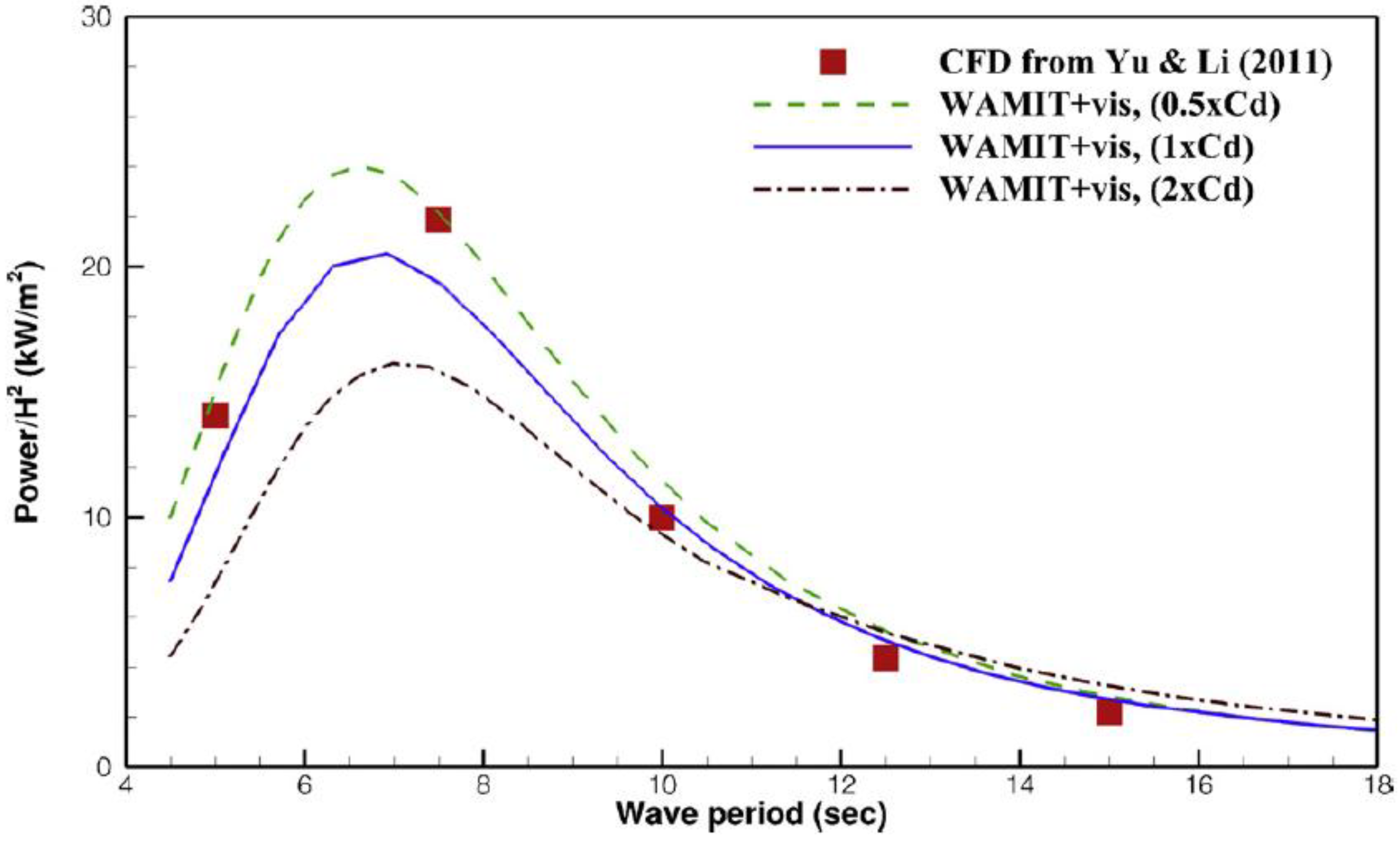
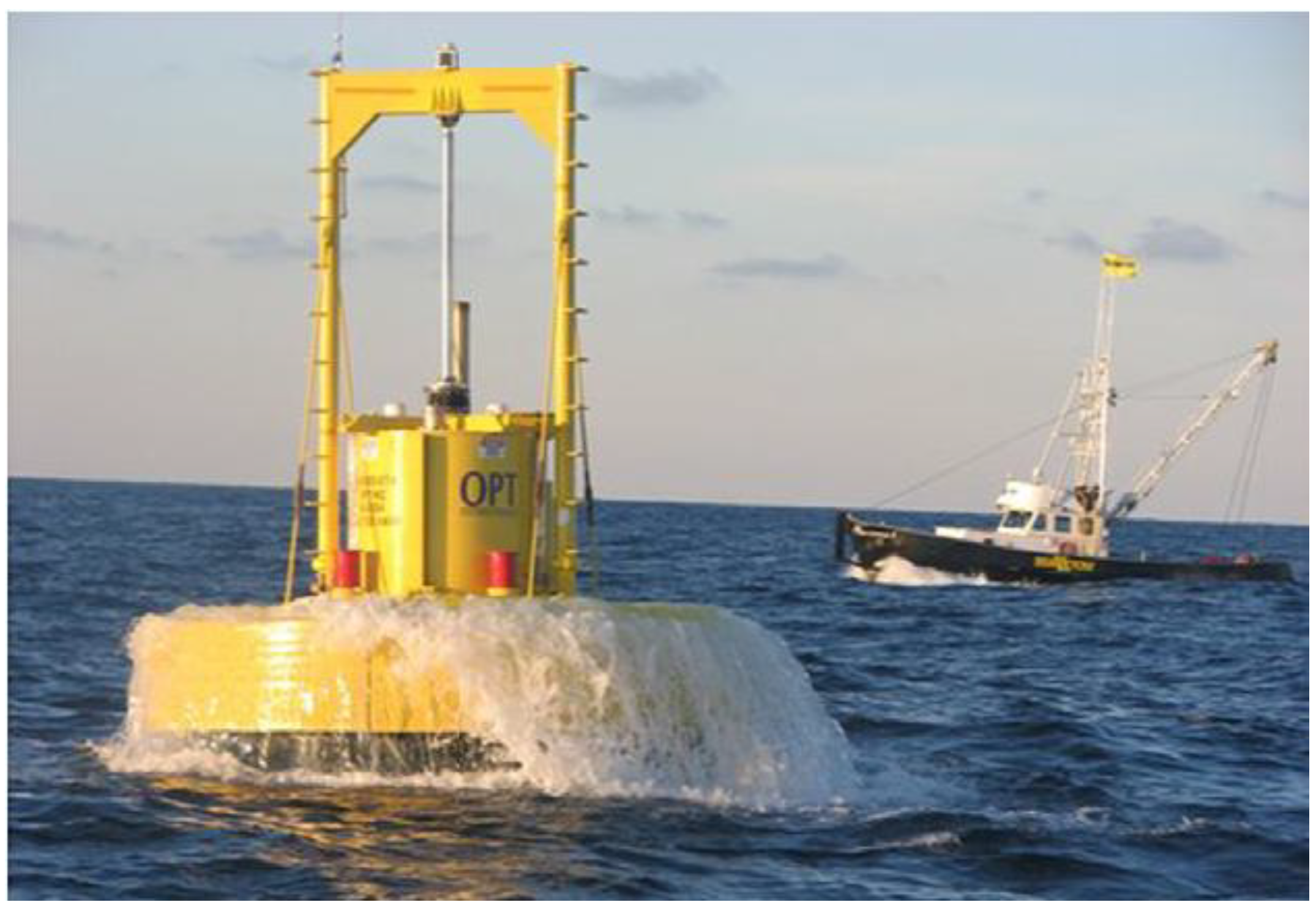
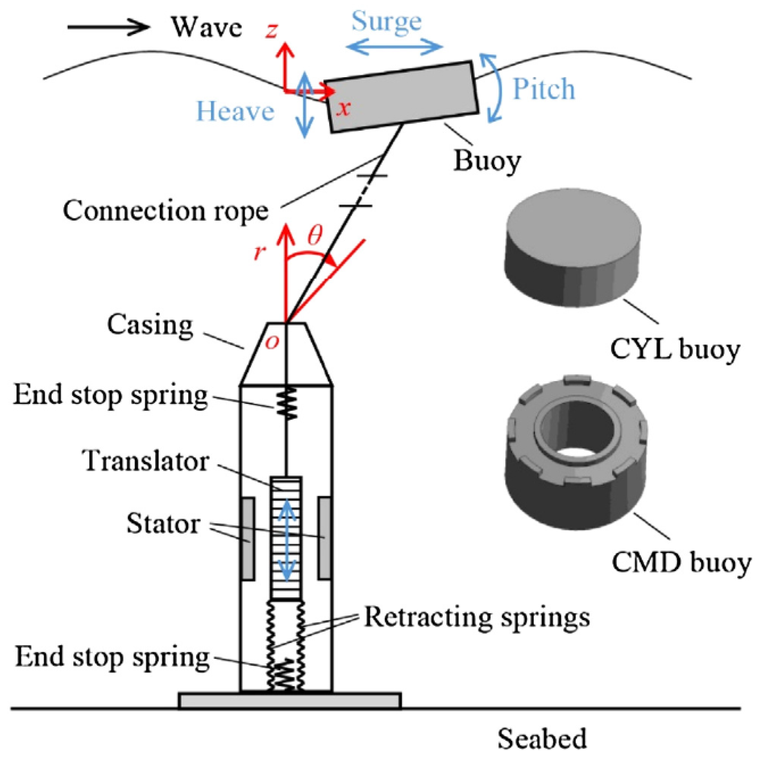
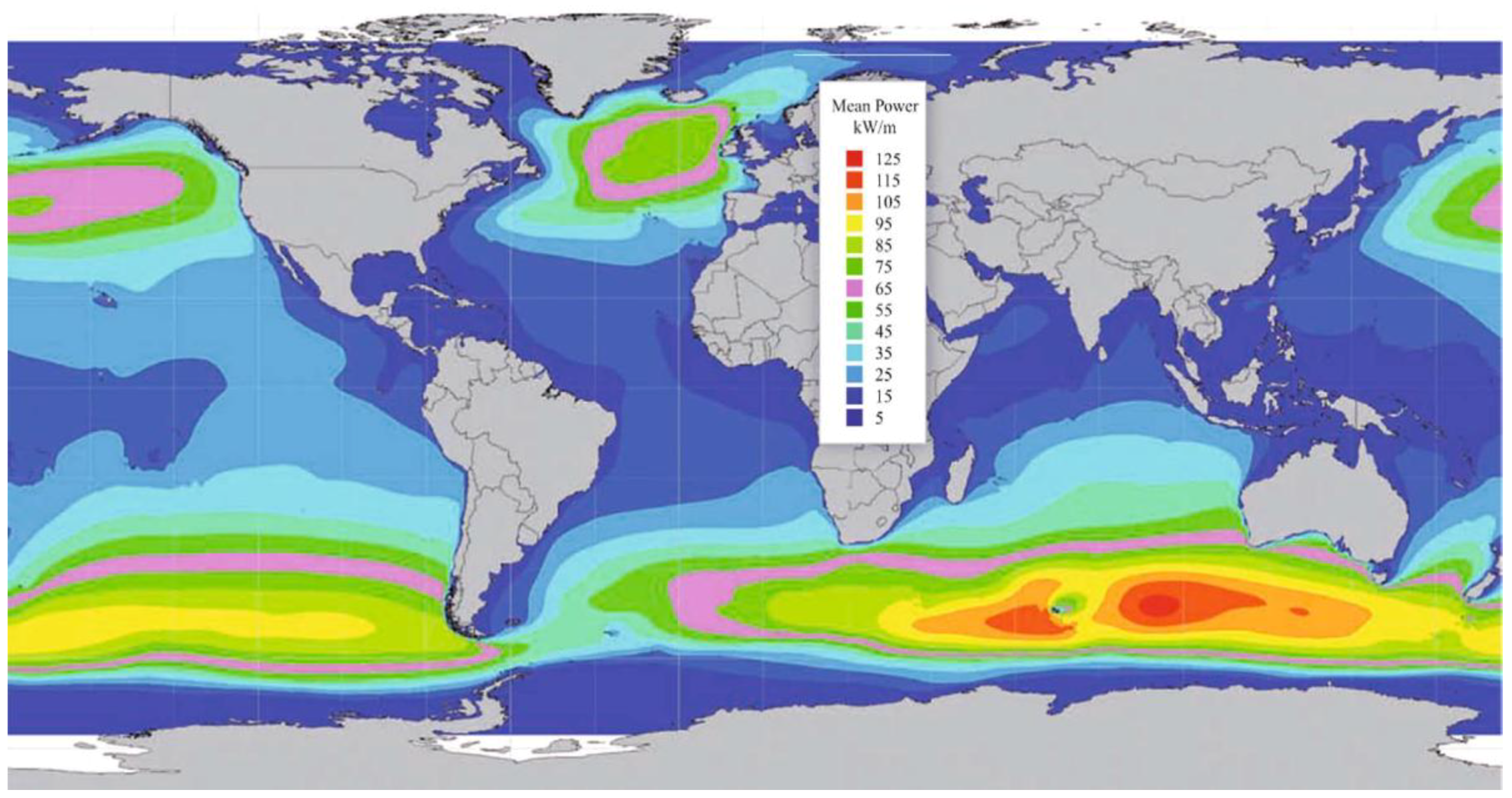
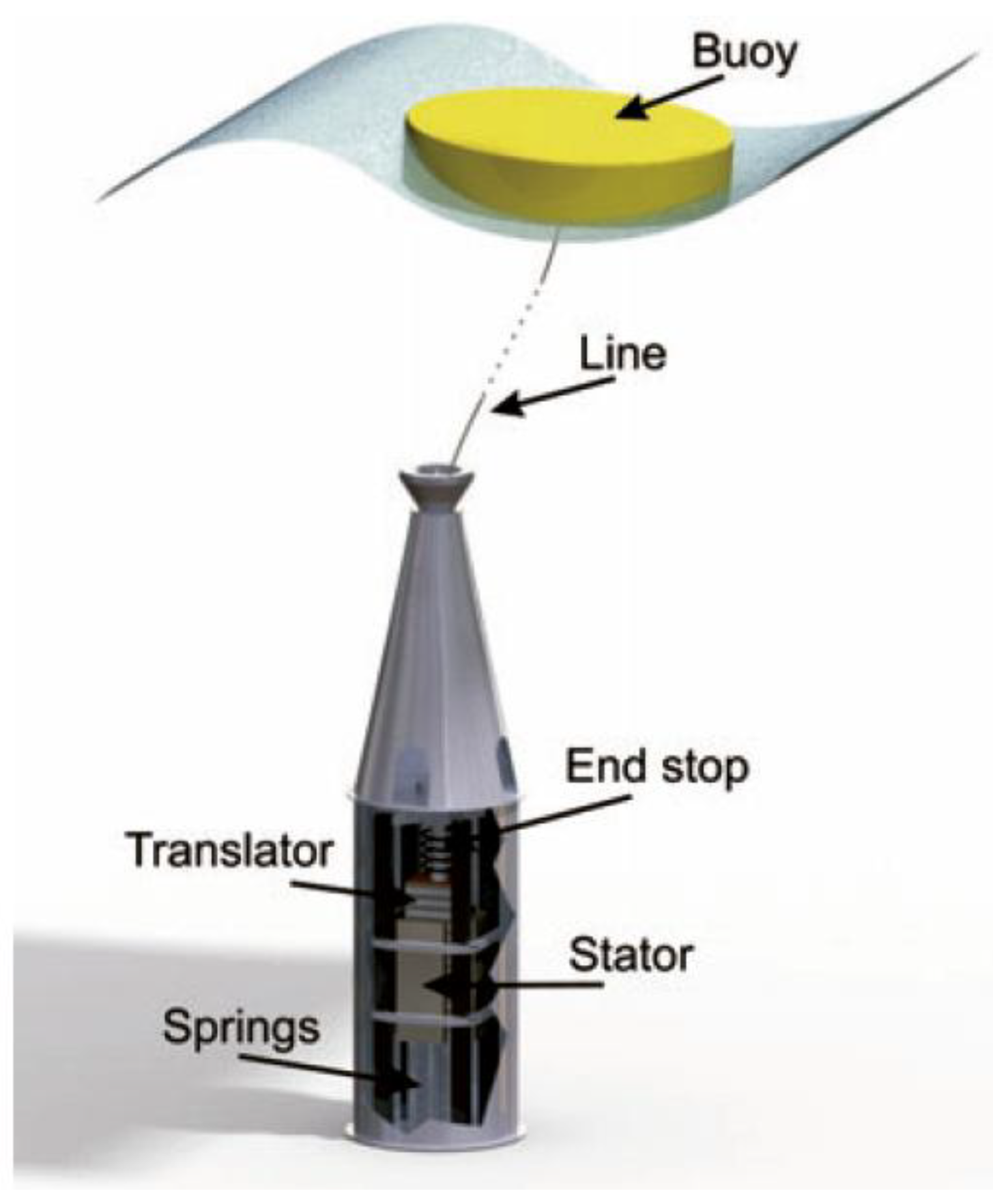
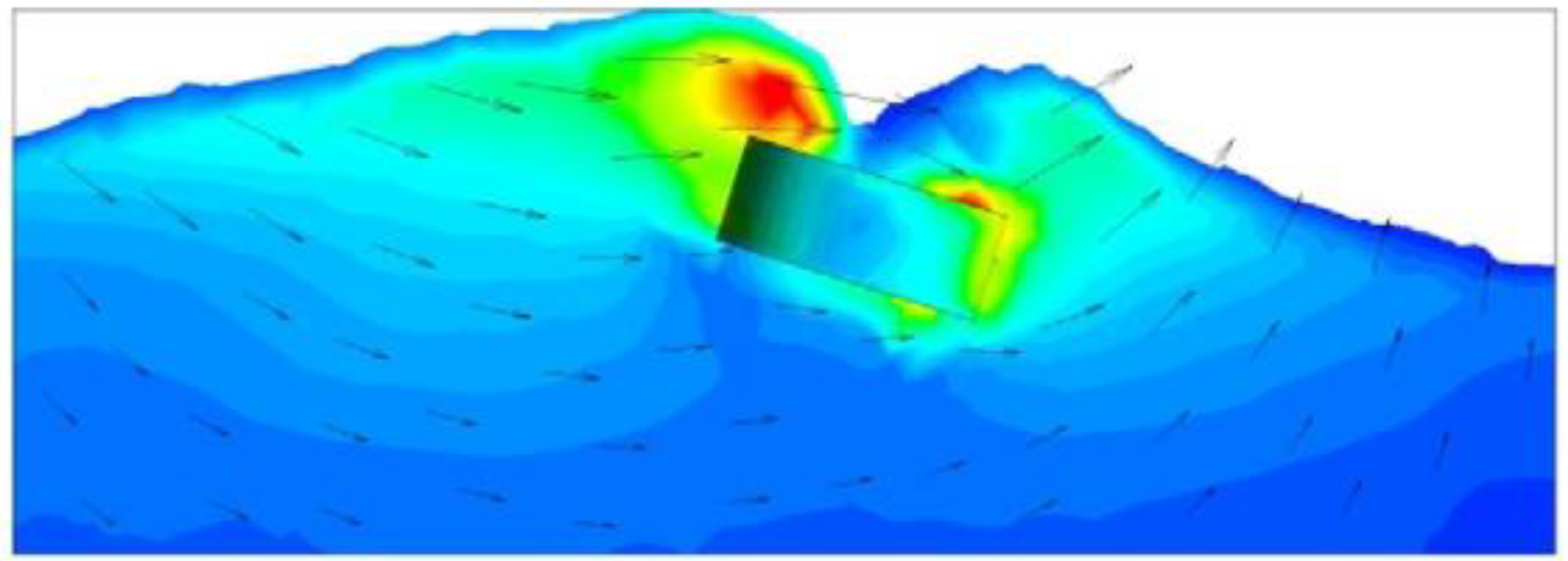
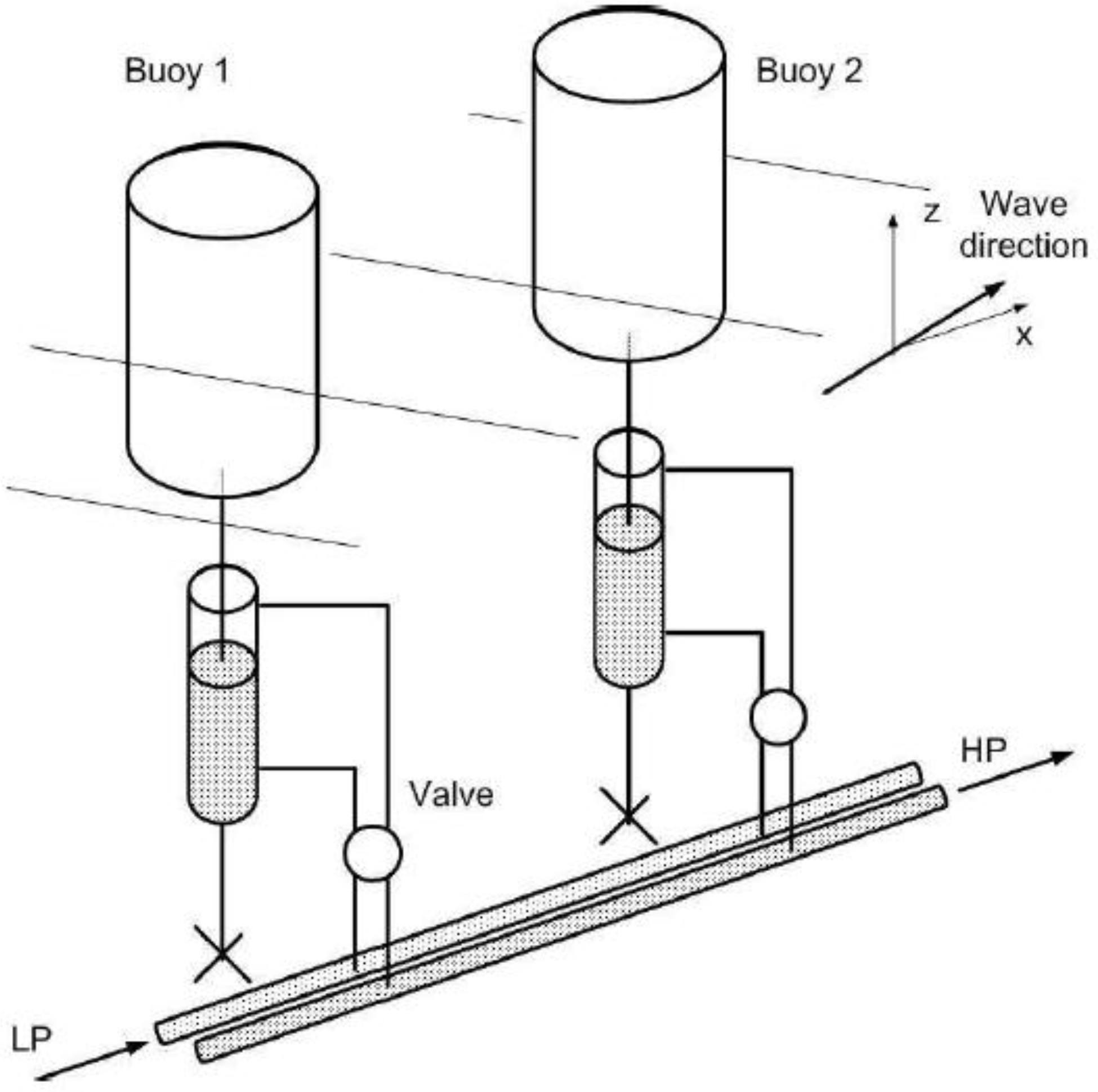
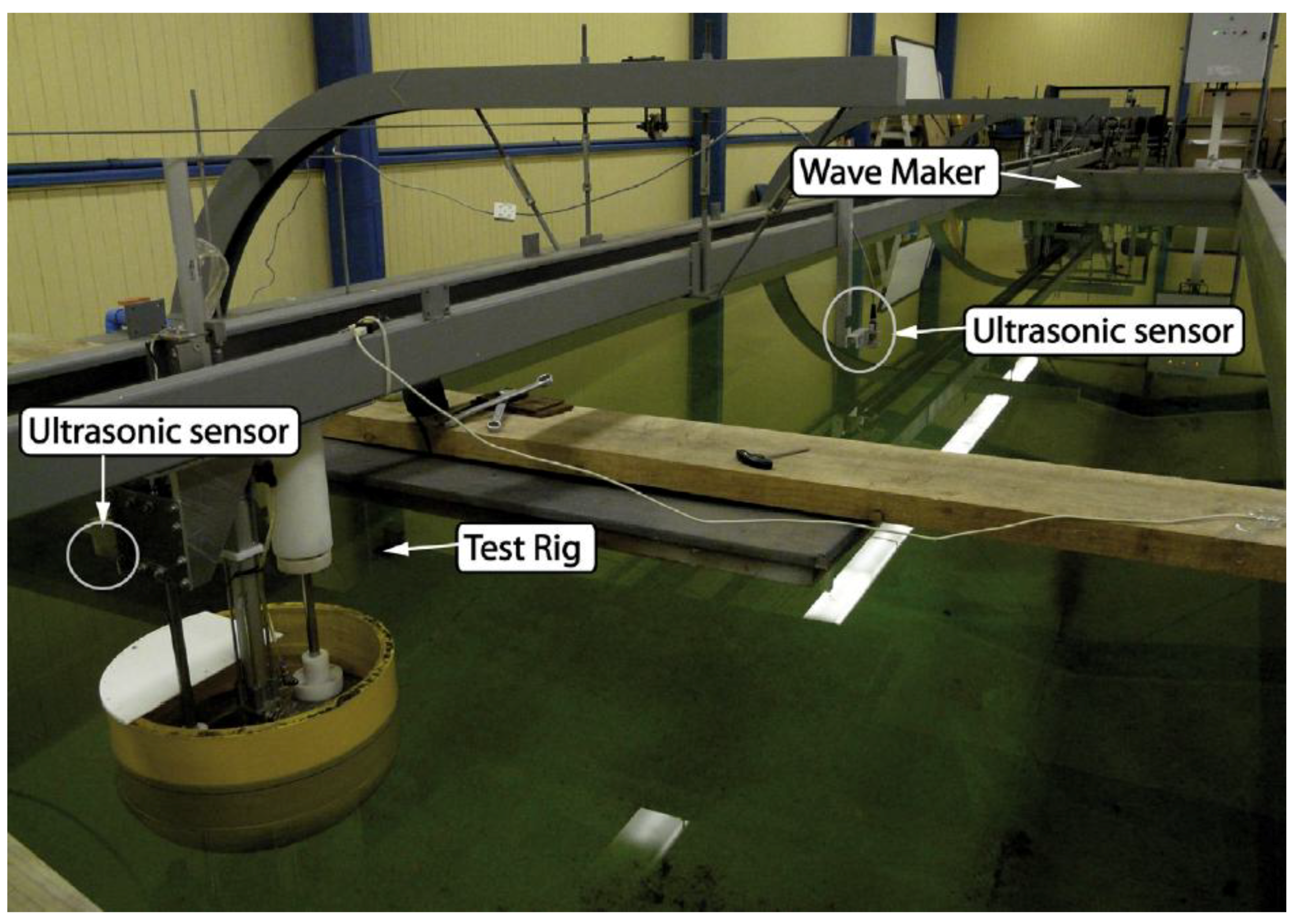
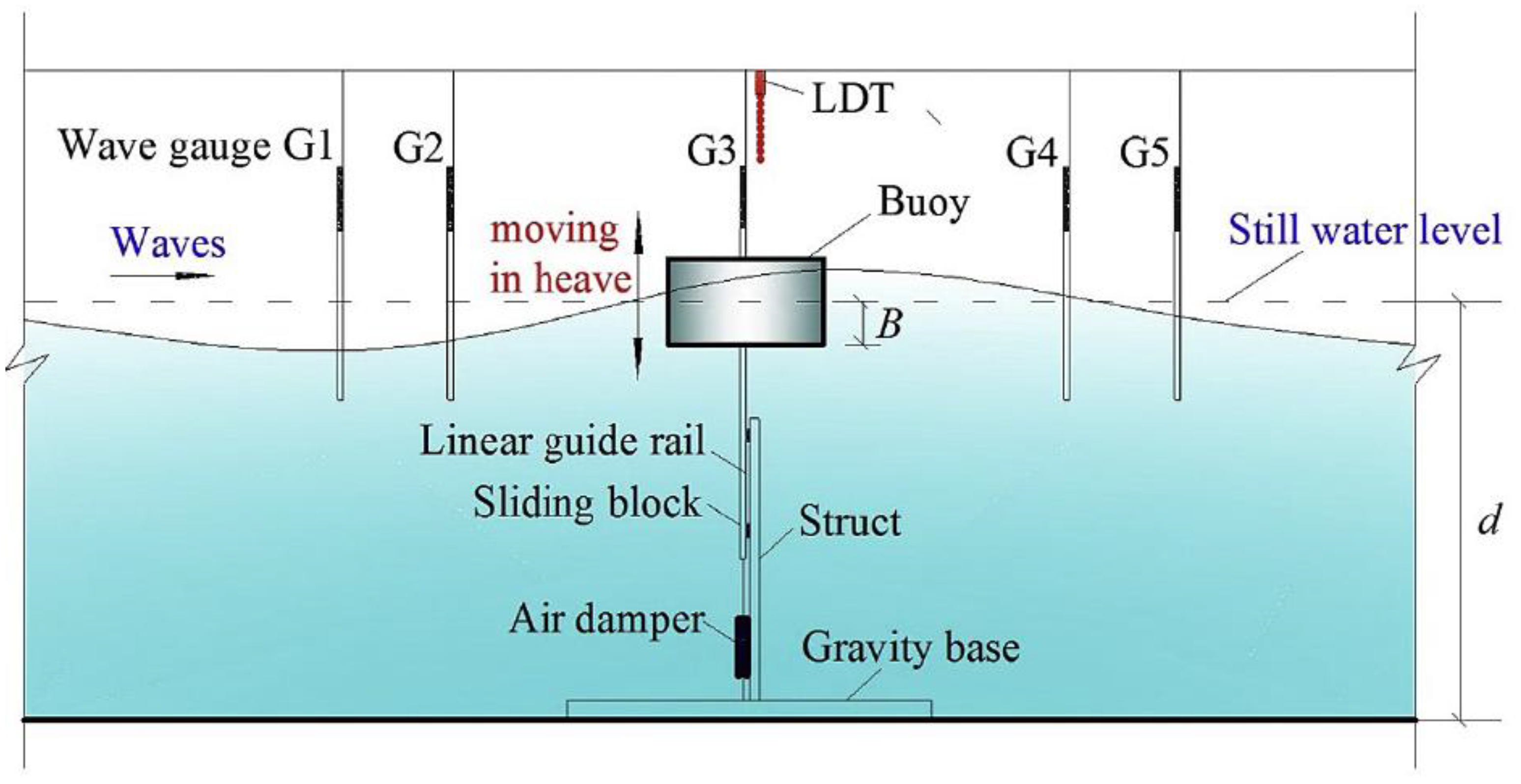
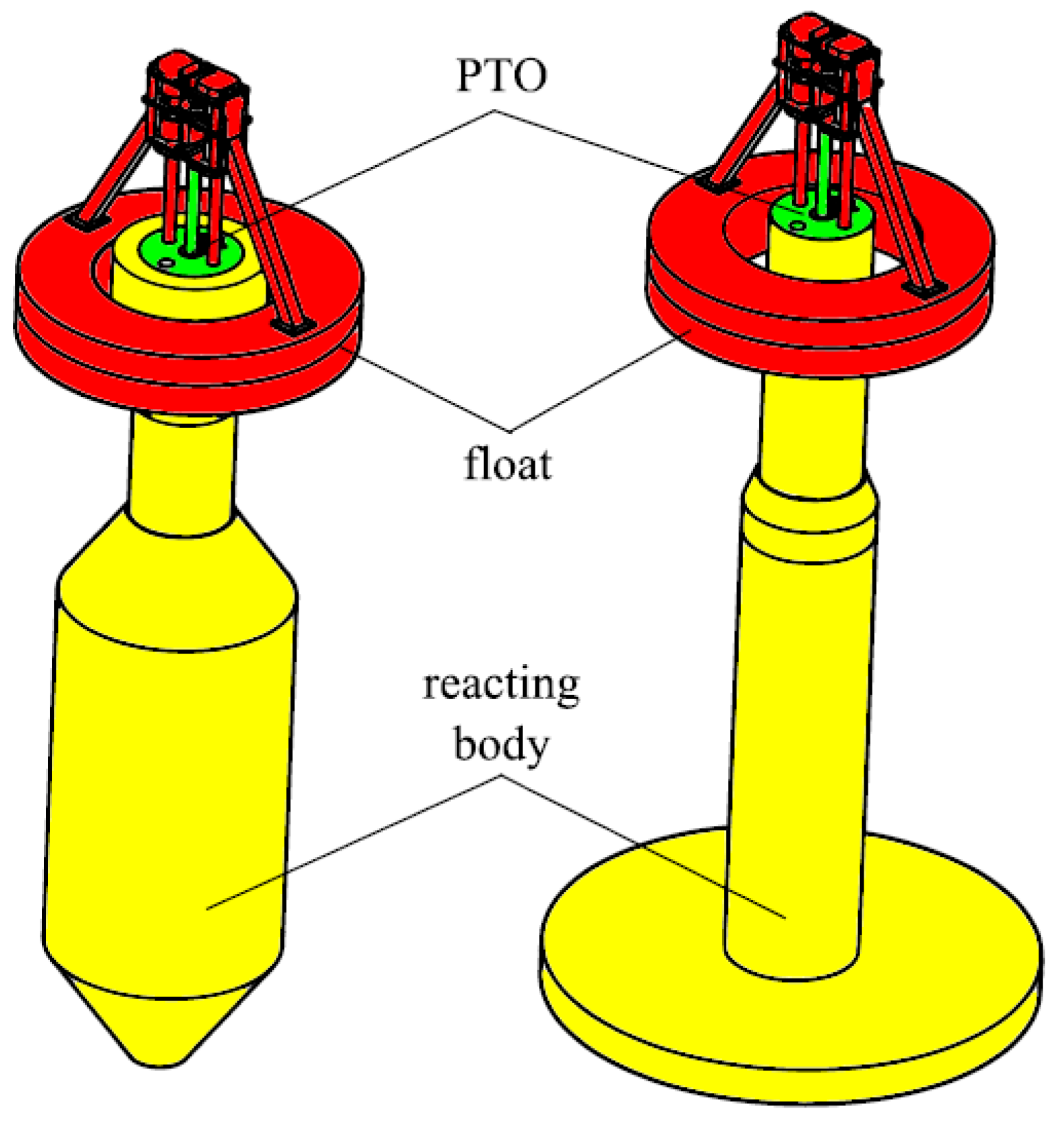
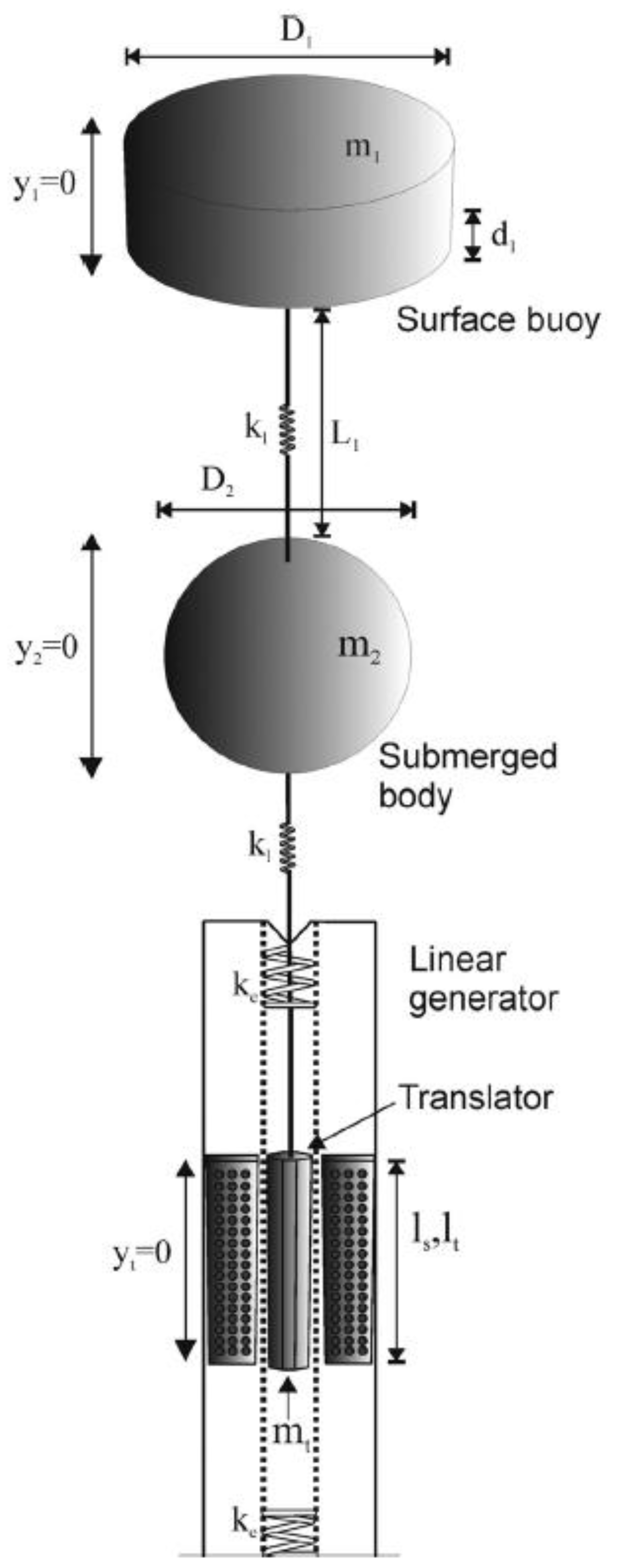
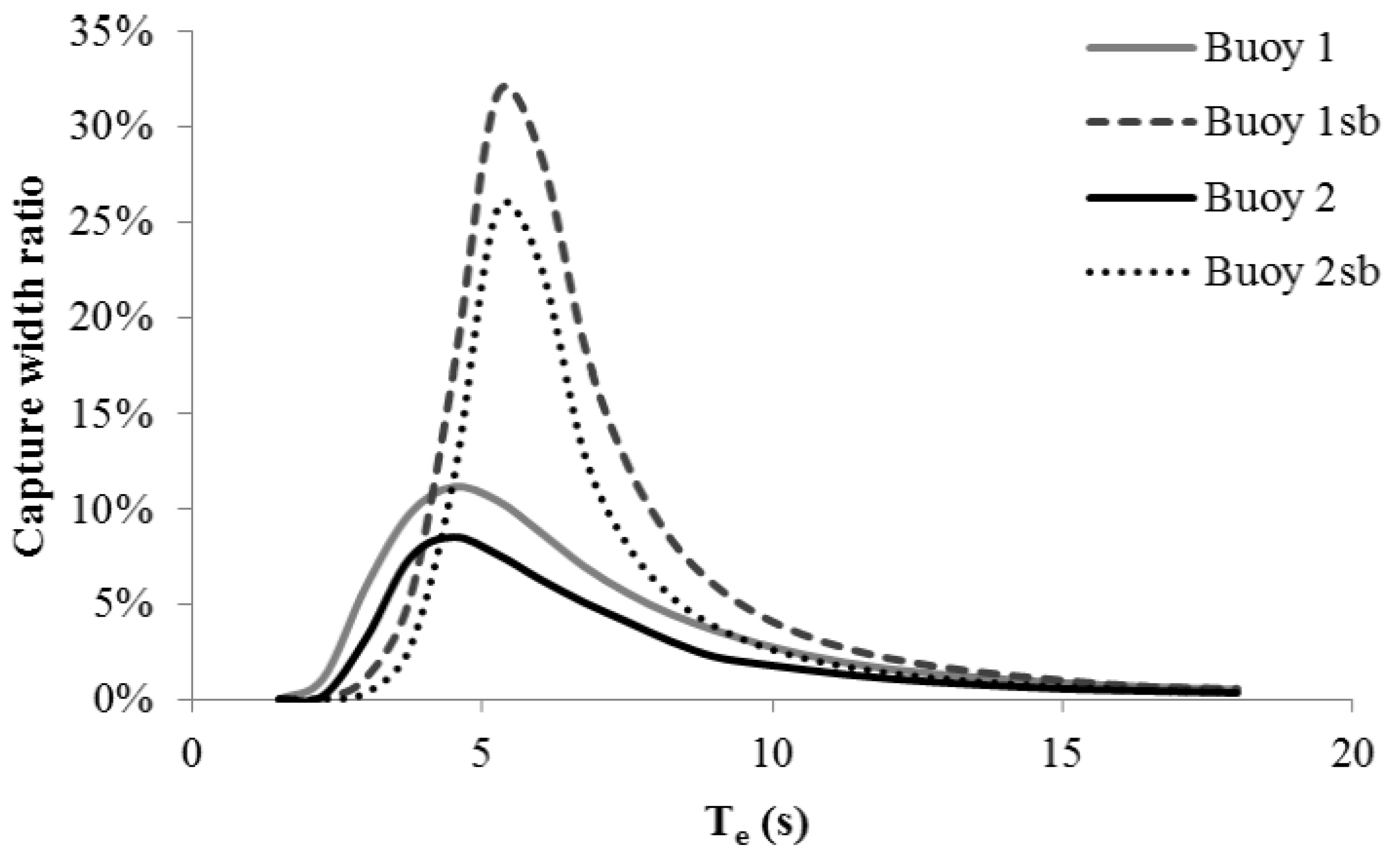
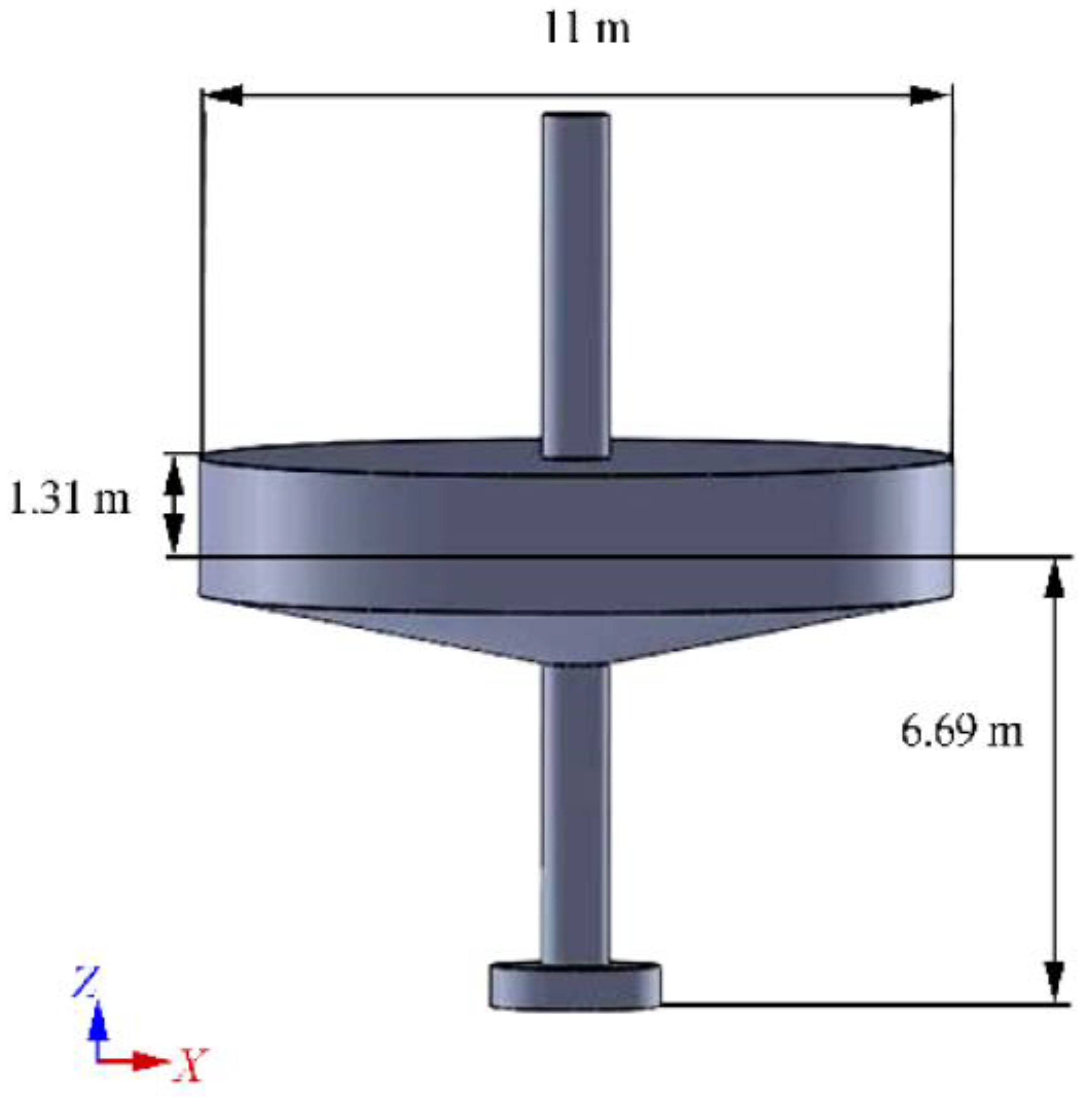
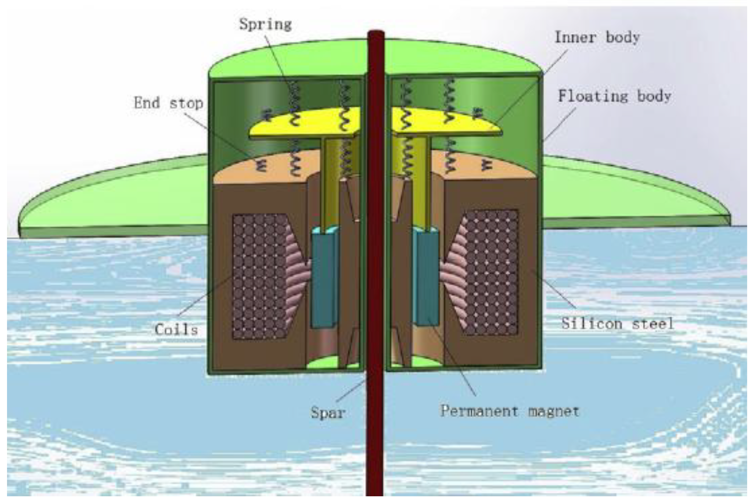
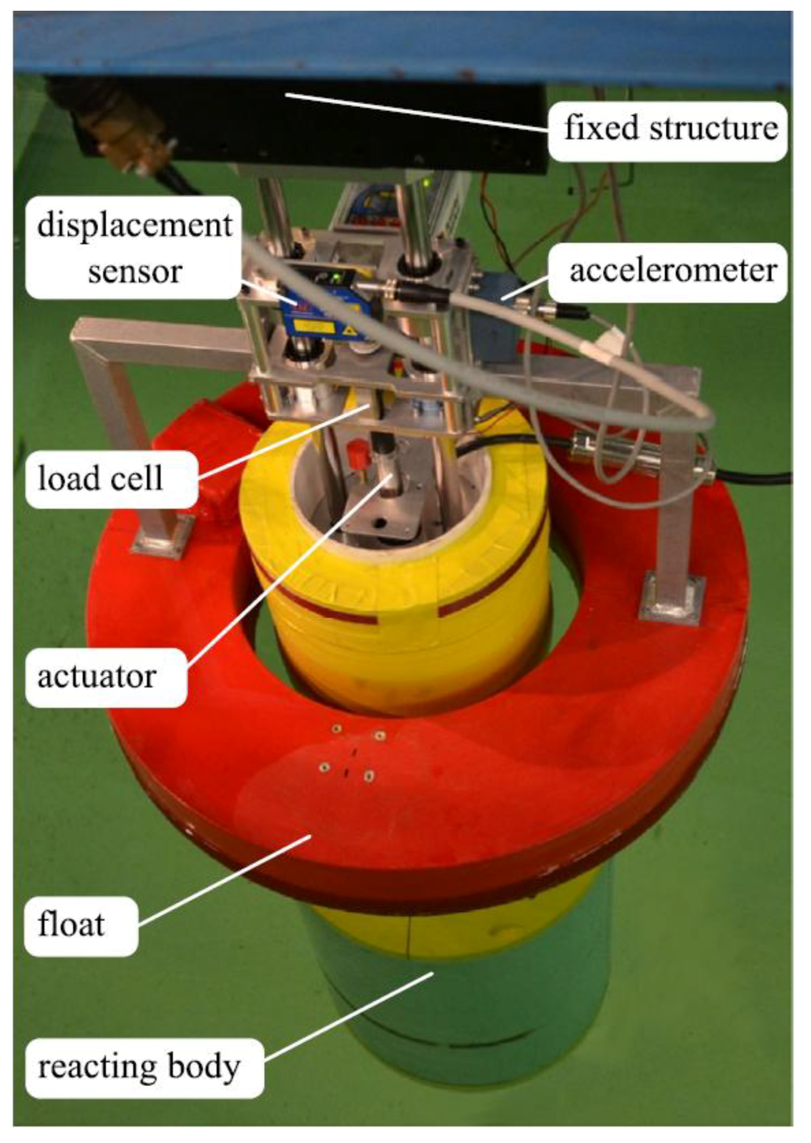
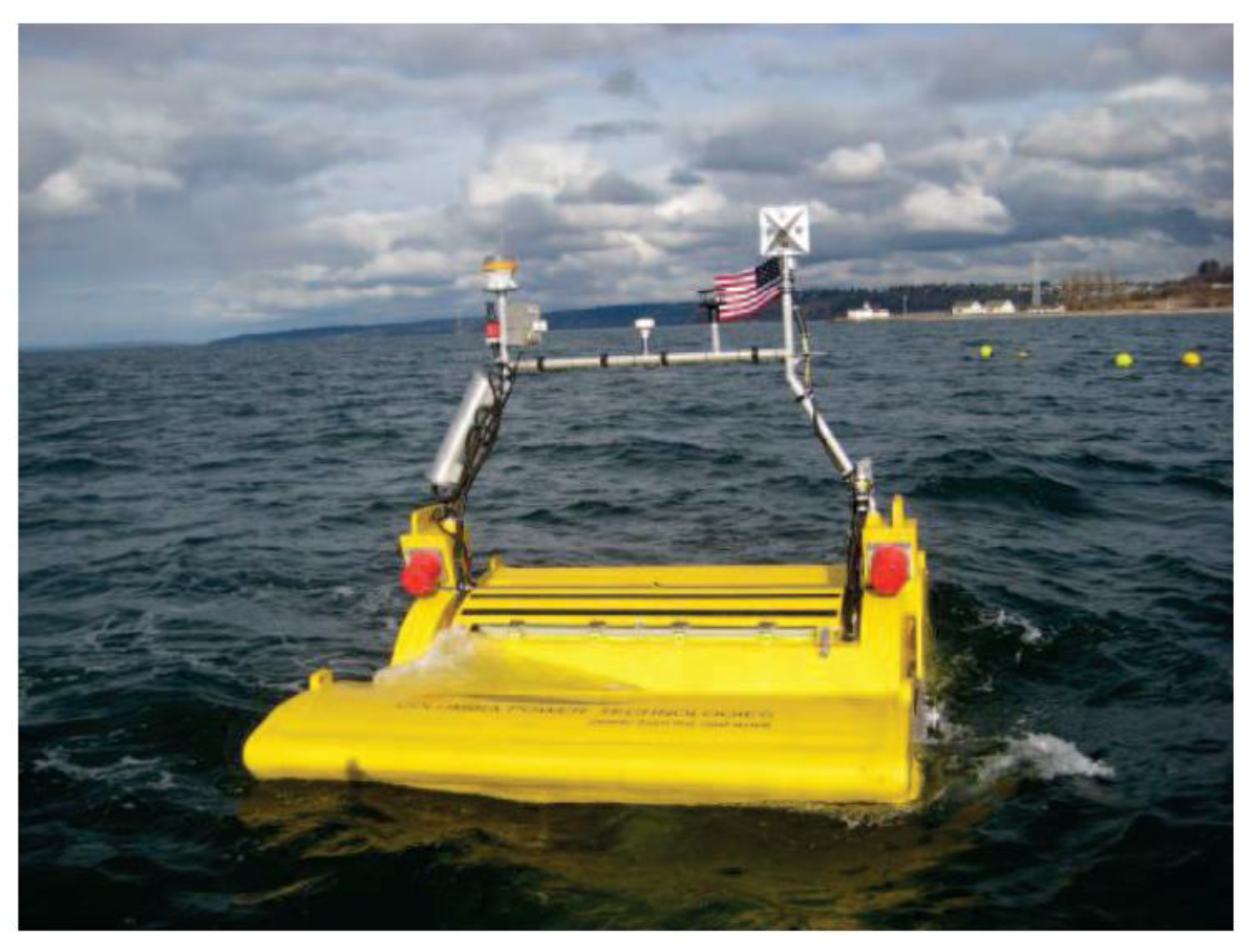
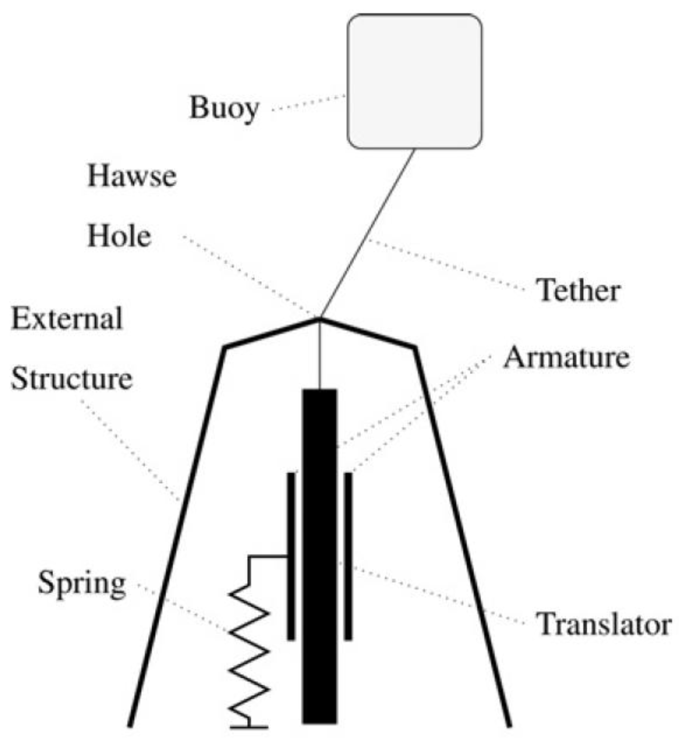
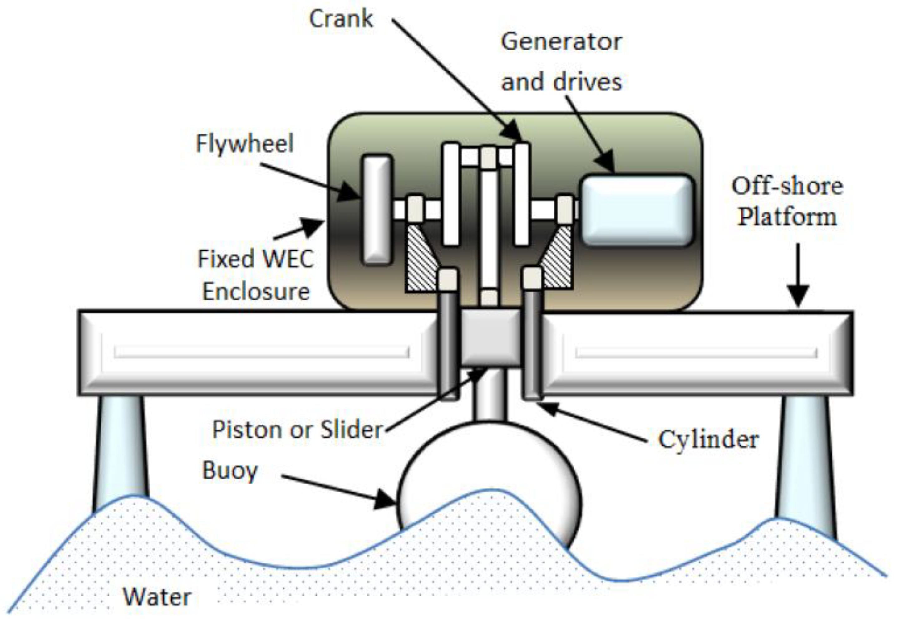
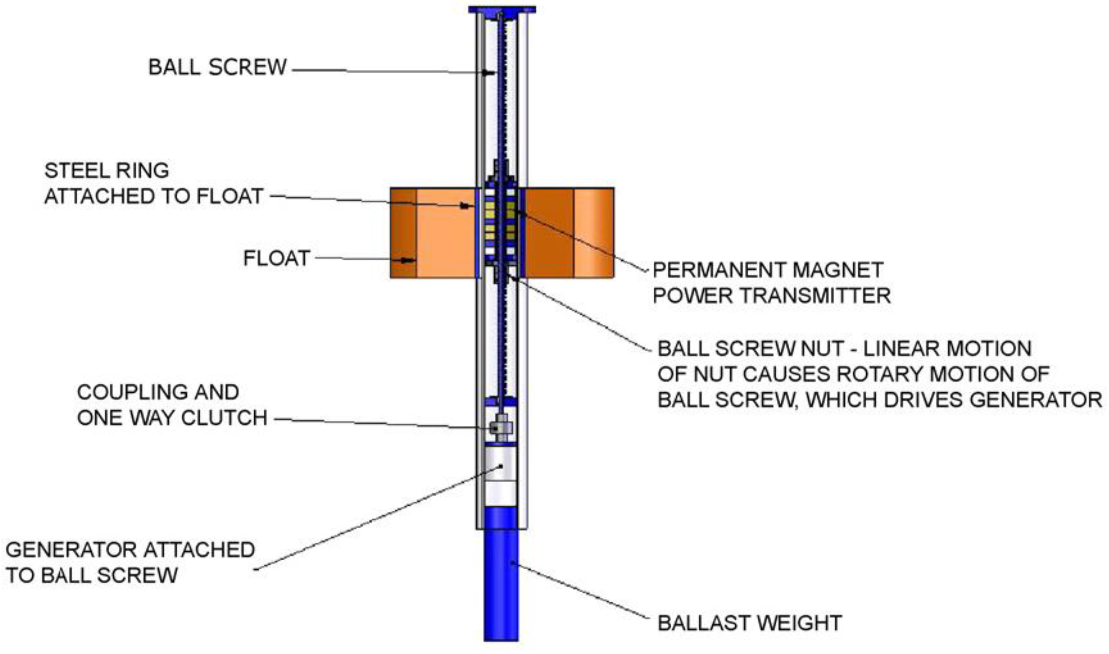
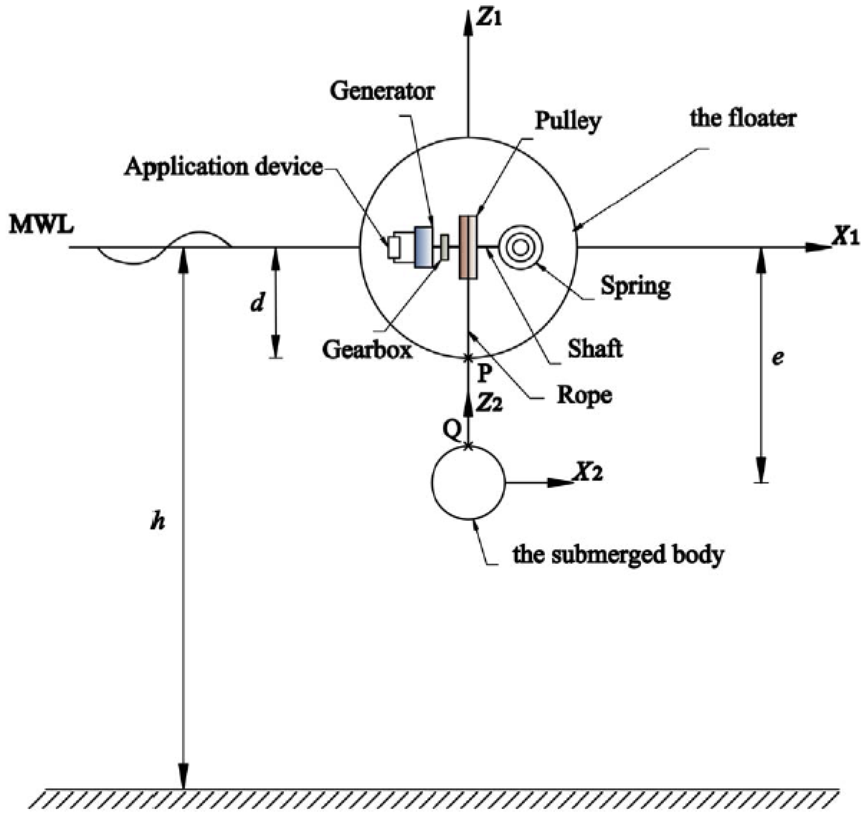
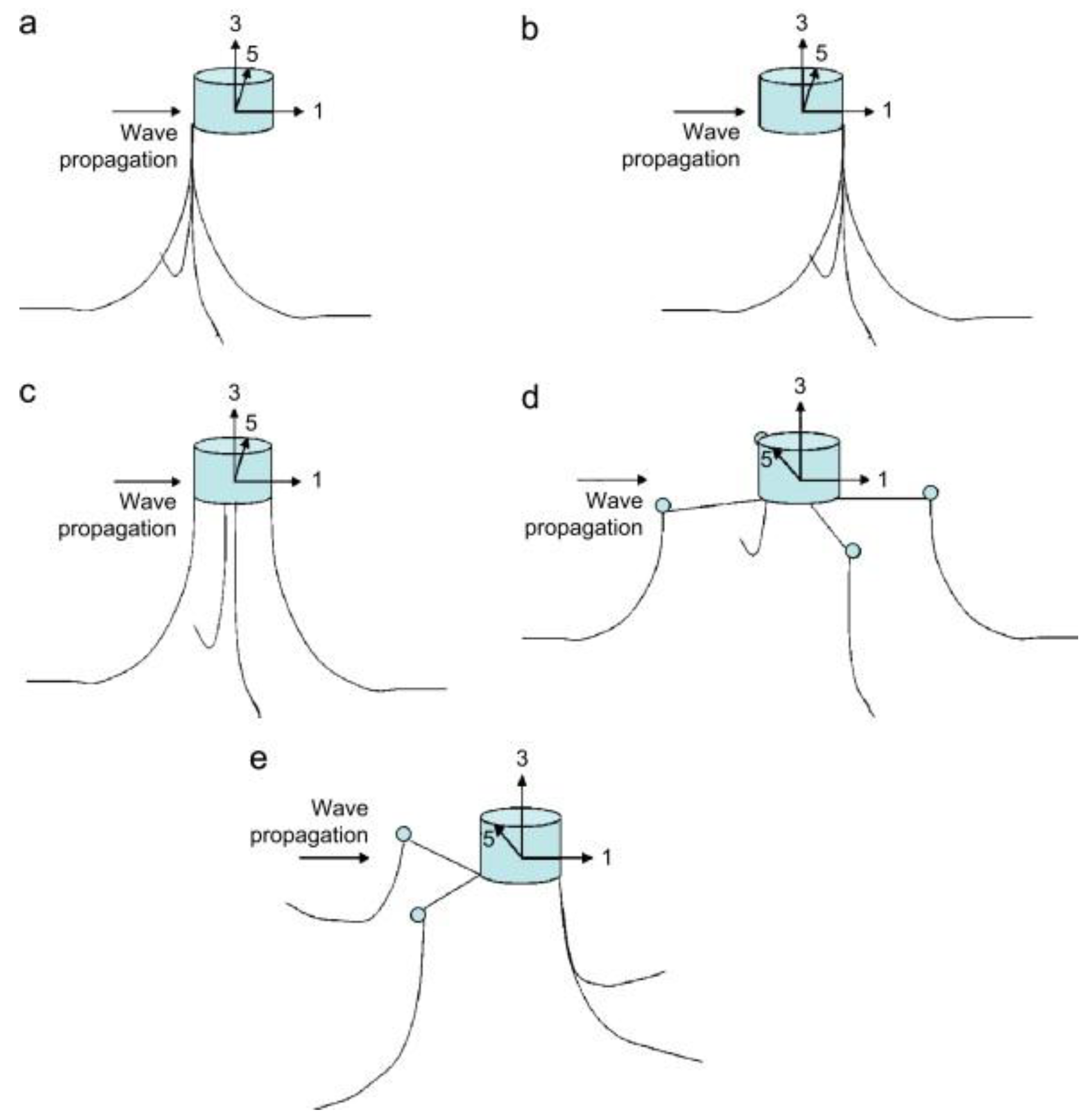
Table 1.
Novel PTOs recently developed.
| Reference | Type | Innovation | Highest Efficiency | Tested/Scale | Target |
|---|---|---|---|---|---|
| Polinder, Damen and Gardner [36] | Linear generator | Transverse-flux permanent magnet | >90% | Yes/Full scale (sea testing) | AWS |
| Ulvgård, Sjökvist, Göteman and Leijon [44] | Linear generator | Forces variations analysis | N.A. | Yes/Full scale | Full scale point absorbers |
| Crozier, McKeever, Mueller, Spooner and Bailey [102] | Linear generator | Snapper spring system | N.A. | Yes/scaled to wave tank requirements | Full scale point absorbers |
| Sang, Karayaka, Yan and Zhang [37] | Linear to rotary | Crank slider mechanism | N.A. | No | Full scale point absorbers |
| Agamloh, Wallace and von Jouanne [105] | Linear to rotary | Contactless force transmission system/Ball screw nut mechanism | 60% | Yes/scaled to wave tank requirements | Full scale point absorbers |
| Liang, Ai and Zuo [7] | Linear to rotary | Rack and pinion motion rectifier | 28% capture width | Yes/scaled down and tested in the sea | Full scale point absorbers |
| De Koker, Degrieck, De Maeyer, Verbelen, Verbrugghe, Vantorre and Vandevelde [106] | Linear to rotary | Planetary gear system with control transmission | 88% | No | Suitable for small buoys |
| Boren, Lomonaco, Batten and Paasch [107] | Linear to rotary | Vertical axis pendulum | N.A. | Yes/scaled to wave tank requirements | Suitable for small to medium buoys |
| Takaramoto, Kashiwagi and Sakai [108] | Linear to rotary | Swinging mass like a pendulum | 34% | No | Suitable for small to medium buoys |
| Dai, Chen and Xie [109] | Linear to rotary | Pulley/spring connected to two submerged bodies | 20% | Yes/1:10 scale in a wave tank | Marine monitoring buoys |
| Hadano, Lee and Moon [110] | Linear to rotary | Closed loop with 4 pulleys | N.A. | Yes/scaled to wave tank requirements | Suitable for small to medium buoys |
| Kim, Wata, Zullah, Ahmed and Lee [46] | Linear to rotary | A working fluid inside the buoy operates a turbine | 35–45% hydraulic efficiency | Yes/1:3 scale in dry lab testing | Suitable for small to medium buoys |
| Ahmadian, Murray, Ghasemi-Nejhad and Rastegar [101] | Two stage linear | High frequency Piezoelectric | N.A. | No | Suitable for cylindrical buoys with large height to diameter ratio |
© 2018 by the authors. Licensee MDPI, Basel, Switzerland. This article is an open access article distributed under the terms and conditions of the Creative Commons Attribution (CC BY) license (http://creativecommons.org/licenses/by/4.0/).
Share and Cite
MDPI and ACS Style
Al Shami, E.; Zhang, R.; Wang, X. Point Absorber Wave Energy Harvesters: A Review of Recent Developments. Energies 2019, 12, 47. https://doi.org/10.3390/en12010047
AMA Style
Al Shami E, Zhang R, Wang X. Point Absorber Wave Energy Harvesters: A Review of Recent Developments. Energies. 2019; 12(1):47. https://doi.org/10.3390/en12010047
Chicago/Turabian StyleAl Shami, Elie, Ran Zhang, and Xu Wang. 2019. "Point Absorber Wave Energy Harvesters: A Review of Recent Developments" Energies 12, no. 1: 47. https://doi.org/10.3390/en12010047
Note that from the first issue of 2016, this journal uses article numbers instead of page numbers. See further details here.