A Novel Energy Optimization Approach for Electrical Vehicles in a Smart City


Laboratory of proceeding, energetic, environment and electric systems LR18E534, National school of engineering of Gabès, University of Gabès, Gabès 6072, Tunisia
*
Author to whom correspondence should be addressed.
Energies 2019, 12(5), 929; https://doi.org/10.3390/en12050929
Submission received: 22 February 2019
/
Revised: 5 March 2019
/
Accepted: 6 March 2019
/
Published: 10 March 2019
(This article belongs to the Special Issue Selected Papers from "International Symposium on Advanced Electrical and Communication Technologies" ISAECT 18)
Abstract
:Electric Vehicles (EVs) have emerged rapidly across the globe as a powerful eco-friendly initiative that if integrated well with an urban environment could be iconic for the host city’s commitment to sustainable mobility and be a key ingredient of the smart city concept. This paper examines ways that will help us to develop a better understanding of how EVs can achieve energy use optimization and be connected with a smart city. As a whole, the present study is based on an original idea that would be useful in informing policy-makers, automotive manufacturers and transport operators of how to improve and embrace better EV technologies in the context of smart cities. The proposed approach is based on vehicles’ and buildings’ communication to share some special information related to the vehicles’ status and to the road conditions. EVs can share their own information related to their energy consumption experience on a specific path. This information can be gathered in a gigantic database and used for managing the power inside these vehicles. In this field, this paper exposes a new approach to power management inside an electric vehicle based on two-way communication between vehicles and buildings. The principle of this method is established in two sections; the first one is related to vehicles’ classification and the second one is attached to the buildings’ recommendations, according to the car position. The classification problem is resolved using the support vector classification method. The recommendation phase is resolved using the artificial intelligence principle and a neural network was employed to give the best decision. The optimal decision will be calculated inside the building, according to its position and using the old vehicle’s data, and transferred to the coming vehicle, for optimizing its energy consumption method in the corresponding building zone. Different possibilities and situations in this approach were discussed. The proposed power management methodology was tested and validated using Simulink/Matlab tool. Results related to the battery state of charge and to the consumed energy were compared at the end of this work, to show the efficiency of this approach.
1. Introduction
Electrical power is one of the important sources of energy in our daily life. It is used in all areas for the rapid development of the economy. The efficiency of the related production systems and power transmission system is required for the sustainable development of the economy and environmental protection [1]. Saving energy is also a goal for consumers and producers. Many studies were initiated in this context. Renewable energy was introduced in this field in order to minimize the electrical power production from combustion-based generators. Related technologies were rapidly developed in order to extract the maximum energy from natural sources under extreme conditions [2,3,4,5].
Electrical energy is also used in transportation systems like high-speed trains (HSTs) and electrical vehicles (EVs). Meanwhile, a problem often related to electric vehicles is their difficulty to save power. Power loss minimization in cars represents a serious challenge for researchers. Even with these problems and according to [6], EVs have gained renewed attention in the vehicle market and the global market. By 2030 it is expected that there will be three times more EV users than the amount recorded in 2011. This is due to the high technology improvement of battery performance and its consequence on vehicle autonomy. Studies have not stopped with the development of EVs, but the aim was to improve the usability of EVs in relation to their autonomy (Au), which remains a serious challenge. Based on various statistics about different EVs, Table 1 provides a classification of various EV models in relation to their Au [7,8,9]. Even when these new statistics are compared to previous versions, users are still afraid of using EVs for long distance travel. According to various tests seeking equivalence between the electrical and the combustible energy consumption of EV cars, we can conclude that 10 kWh/100 km is approximately equivalent to 1 L/100 km and this is valid for highway travel, so saving energy will expand EV autonomy and thus save money.
To increase the vehicle autonomy, managing the power inside the car is one solution to save energy; the idea is based on the minimization as much as possible of the electrical energy consumed when the car is in motion.
1.1. The EV Power Management Problem in the Literature
The power management problem inside an electric vehicle was treated in numerous studies. The objective is to reduce the energy consumption and increase battery life through optimal control. Therefore, various methods and strategies were proposed to achieve this goal.
Some presented works have exposed a useful solution for managing power, which approach consists in providing the EV with a hybrid charging system, which contains an ICE engine and an electrical generator [11,12]. In this case, the battery can be charged even when the car is in motion. However, the problem in this case is related to the internal system complexity and the high prices of these car models.
Another mentioned solution is based on renewable energy sources like solar energy [13] or the energy recovered during the deceleration phase called also regenerative braking [14]. Those systems are effective, but the quantity of energy recovered is not sufficient, especially during highway use. According to [15], regenerative braking systems cannot supply 5% of the battery power needs when fully charged.
New charging systems based on wireless circuits were identified as a suitable solution for highway road cases. In [16] the authors discuss these systems and describe their advantages and inconveniences. The problems are also related to car speed and the charging system’s complexity. The recharge level depends on the car’s speed and road length. All these techniques for charging vehicles are acceptable and efficient, however, the same problem remains – they are always attached to each model and its relation to system complexity.
Related to the autonomy amelioration objective, several software approaches and strategies were proposed in the literature in order to improve the energetic performance of vehicles. In [17] and [18] the authors used intelligent techniques for power optimization in a hybrid vehicle. Also, in [19,20], the authors’ work was based on fuzzy techniques for managing online the power inside the vehicle.
Road data, drivers’ demand and sensor outputs are also used for managing power inside vehicles [21]. In this work, the authors proposed solving an optimization problem for managing power. A different optimization problem, which regroups several parameters related to the battery power, internal combustion engine, and the traction power were expressed and studied in [22]. From another point of view, the power management problem is resolved using a PID and fuzzy controller in order to compare the performance of the electric vehicle to an IC engine vehicle [23].
Another intelligent solution was proposed in [24], where the authors proposed a data-driven equivalent consumption minimum strategy (ECMS), that determines the equivalent factor (EF) using an artificial neural network.
According to the review published in [25], two energy control strategies can be used for managing power in a hybrid electric vehicle. The first method is based on the fixed rules principle and the second one is related to the optimization problem. The authors were proved that the neural network can be classified as a solution for the optimization problem. Base on the advantages revealed in this review, the neural network solution was considered for building our power management approach.
Based on various studies, the major applications for managing the power of an electric vehicle will be done inside the energy control system, which will control the car according to the own vehicle parameters and according to the used algorithm [26,27]. This requires a high-speed processor for handling those mathematical equations [27]. Our approach simplifies the power management for an electric vehicle and transfers the power management problem outside the vehicle.
The uniqueness of this work is related not only on the user control method for managing power, but rather the idea is related to how to profit from the external environment surrounding the vehicle, especially the privileges of the smart city. Detailed descriptions will be provided in the next sections.
1.2. The Smart City and Electric Vehicle Relationship
Electric cars, electric buses, and neighborhood electric cars can be collectively classified as EVs and will be the principle transportation system in the future. The tendency of reducing gas emissions in the city will guide total electrification of the transport system [28]. However, the efficiency of these new transportation systems cannot be guaranteed in an ordinary city, as in practice new problems, related to the power distribution and traffic organization, have appeared. Therefore, a smart city can help achieve this national vision [29].
A relationship between the smart city concept and electric vehicles has existed since the appearance of digital devices, such as sensors, camera, actuators, smartphones, and smart appliances. The possibility of interconnecting all of those devices and creating communications between them, makes the city connected and intelligent. This intelligence then helps to manage the city healthcare, water and weather systems, city security and to design better power distribution and power management strategies [30,31].
The presence of EVs in a smart city demands especially efficient and intelligent charge scheduling techniques. Various works have proved that scheduling in smart distribution systems helps minimize the operational costs by reducing electricity bills [28,32,33,34]. On the other hand, problems related to parking or vehicular traffic can also be resolved by the smart city concept. In effect, several studies have proved that a smart city will encourage the use of electrical transportation systems, such as electric cars and electric buses, in which the problems related to the high recharge delay will be eliminated in the future [32,35]. Smart cities can also be beneficial to saving energy in relation to EVs, and several tests and discussions in relation to this topic were presented in [1,36,37].
With the rapid development of information and communication technologies, new vehicles are equipped with a wireless communication systems, so connected vehicles on the go are proactive, cooperative, well-informed, and coordinated, which will pave the way for supporting various road safety applications [38]. Therefore, the vehicle to building communication (V2B), or the vehicle to road communication (V2R) is possible in a smart city, using the vehicle to internet connectivity (V2I) system [39]. All the vehicle information detected by the installed sensors, can be transferred to buildings or roads and the inverse will be easy too [40].
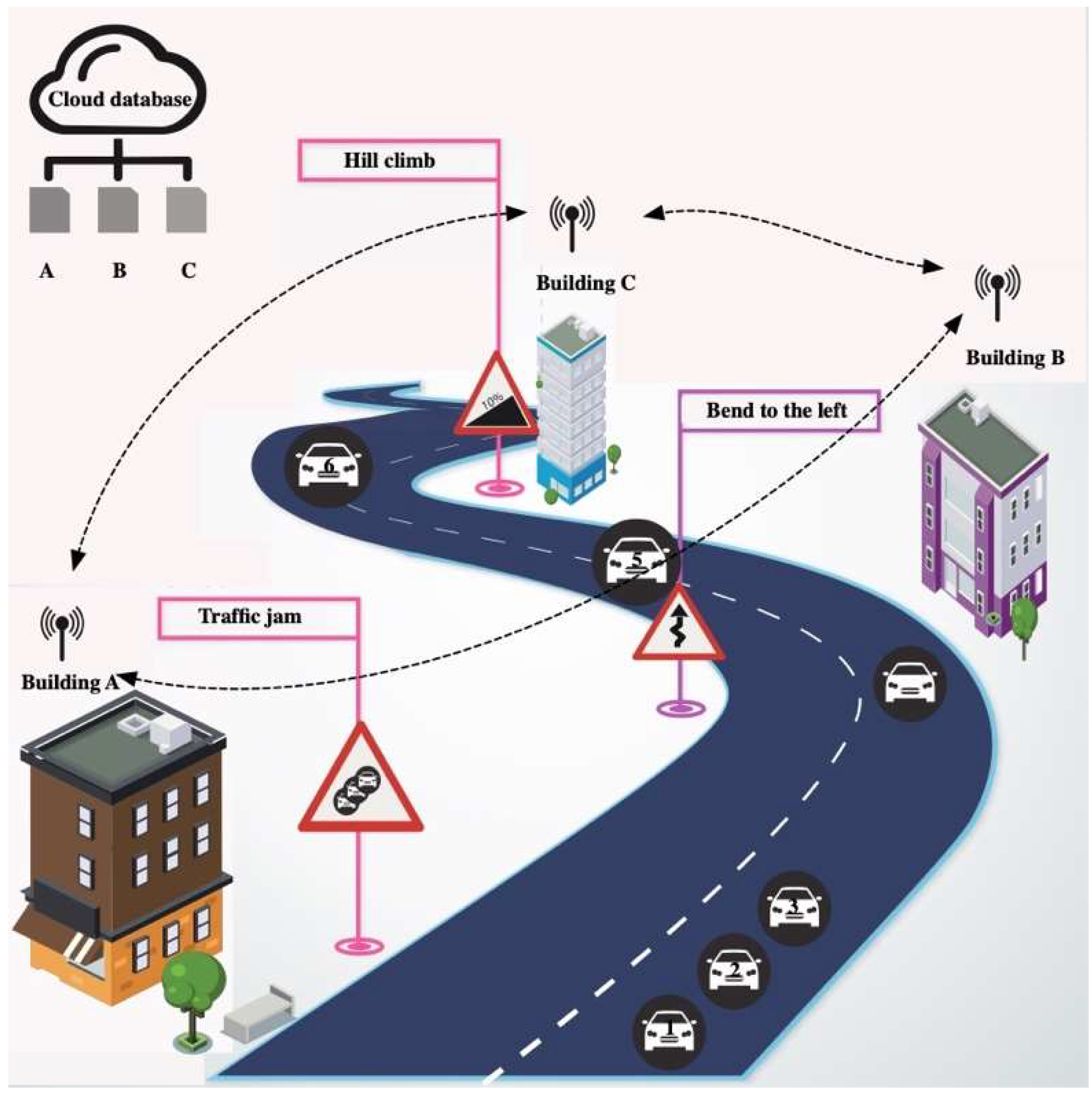
The conventional relationship between the smart city and an electric vehicle can be summarized as in Figure 1. In general, information about the recharging systems, the road conditions, and the parking status is available [41]. Effectively, each vehicle can be informed about the optimal road under the present traffic conditions. The smart city concept and particularly, the smart grid system can help to manage the vehicle to grid (V2G) concept to facilitate quick recharge times [32]. If a traffic jam is detected and the vehicle is informed, this will indirectly help to resolve the traffic problem. The proposed approach extends the relationship between EVs and smart cities for managing the power inside the vehicle on the road.
Effectively, the searched optimum parameters will be calculated outside the vehicle taking advantage of the smart city infrastructure. The high technologies used inside a smart city will be a benefit for our proposed technique and then it is also possible to save energy inside the EV.
1.3. How a Smart City Can Help Managing Power in an Electric Vehicle
Based on that equipment, if each vehicle can be identified and share its data related to the weight, speed, state of charge of the battery, driving method, vehicle position on the map, energy consumption profile and some other information, all these data can be gathered and vehicles can be classified into specific classes. It is then possible to speak of the concept of “energetic experience” of each vehicle on a specific road. According to this data, there is an optimum solution that can be calculated and identified.
Three possibilities exist for exchanging information with vehicles in a smart city. The first case is related to the possibility of communication between vehicles (V2V). The second possibility is related to road and vehicle communications (V2R) and the third situation concerns vehicle and building communication (V2B). This depends on the equipment used in each case. If roads are equipped with the needed facilities, such as sensors and cameras, road and vehicle communication and the inverse is possible. If buildings are equipped with the necessary tools, as cited before, building and vehicle communication and the inverse can be guaranteed. However, each case is characterized by some advantages and inconveniences. Table 2 gives the points of view for using each case and classifies the importance of each case compared to the others.
According to Table 2, V2B is the best communication solution, regarding numerous points such as the equipment safety, the cost of installation of equipment and especially for the electric power availability, which will be useful for the equipment and make installation easier. Therefore, the V2B protocol is used in this work for building the proposed power management approach. We must indicate that the same approach is applicable for a V2R protocol. The V2V protocol can be guaranteed even if vehicles are not in a smart city, however, one vehicle cannot connect with all other vehicles. Generally, the communication between vehicles can be guaranteed only between two or three vehicles in a specific road zone. However, V2R and V2B protocols can be useful for a larger road map.
According to the V2B communication protocol, it is important to indicate that all vehicles’ data will be transferred to buildings and the optimum solution will be calculated in the corresponding structure, which represents the critical road situation, and then transferred to the vehicle.
Here, the optimum solution is related to the reference acceleration profile. As an example, suppose that a vehicle V1 will follow a road X, which contains a building B, with an acceleration M1, and the same road was traversed by many other vehicles Vi with different accelerations Mi.
The data related to the vehicle weight, acceleration, the required power battery state of charge, speed, etc…, will be transferred to building B. Then, the proposed algorithm will search for the optimum solution according to the energetic experiences of the previous vehicles (Vi). Finally, building B will provide V1 with the optimal acceleration Mop. Vehicle V1 will take then it into account and limit M1.
Hundreds of vehicles may be driven every day in front of those buildings. The optimal driving solution according to each specific situation can be calculated using all the gathered driving data, then each building provides the vehicle with the best decision, which is equivalent to the optimum relation between energy and acceleration. That information can be exchanged between buildings to obtain an optimal control method over longer distances, thus, the energy of the vehicle is optimized. Each vehicle can also optimize its own control system. The driver control is not the same for all the drivers. Total energy consumption is related to driver habits. In relation to the vehicle position on the road, like bends or hill climbs, the driving mode will have a direct impact on the energy efficiency and on vehicle autonomy. Essentially, two algorithms will be used in this work, the first one will be related to the vehicle’s classification and second will define the optimum solution according to the existing database.
The proposed approach was tested in a simulation and the obtained results show an energetic gain with this novel methodology. The paper is therefore organized as follows: after this Introduction section, the electrical vehicle model is discussed, defining its interior components and the objective energetic expressions. Next, the problem is formulated and the proposed solution is detailed and explained. In this section, the relation of the smart city concept and vehicle power management is summarized before presenting the conclusions and in the light of this circumstance and to prove the success of the proposed approach, simulation results for a simple example of six vehicles operating in a smart city are generated and presented.
2. Electrical Vehicles and their Basic Components
Electrical vehicles are classified into two categories: hybrid, and pure electric vehicles. Each model has its own advantages and problems. Pure electrical vehicles are friendlier to the environment, so the world tendency is to use these EVs [24,42,43] and therefore, research in this area continues and newer EV versions aiming to optimize battery technologies, charge techniques, then main motors and to the internal control algorithms are being proposed. The objective is to maximize the injected power from the external sources and minimize energy losses inside the car. For these reasons the focus in this paper will be on a pure EV model. Figure 2 shows this EV and its components. The basic version is composed of a battery system which is connected to an inverter to feed the motor. A principle controller organizes this overall system.
This controller is the supervisor of the power source inside the car. It will calculate the needed and used power based on real-time driver demands. According to various studies, the needed and the consumed energy can be evaluated or estimated using analytical models of the car components. Several other sensors are used in the new EV versions and their role is very important for determining the car control phase.
2.1. Modeling of Principal Components for an Electric Vehicle
In all this work, the results are obtained after using the mathematical models of the EV components and related to vehicle torque “Cv”, total Mass “Mv”, electric motor power “Pm”, battery Power “Pbatt”, battery current “Ibatt” and instantaneous battery state of charge “SOC(K)”, respectively, shown in Equations (1) to (6):
All of the notations used are summarized in the acronym list et the end of this paper.
2.2. Related Energy Expressions for an Electric Vehicle
As mentioned in [44], the state of charge of an electric vehicle is related to several parameters and the driver acceleration will affect the battery SOC. The authors proved in this work that the acceleration is inversely proportional to the remaining battery SOC. Equation (7) presents the percentage of the state of charge of a lithium battery, fully charged at the departure, in function of an acceleration value, noted by (Acc). SOC(0) indicates the initial state of charge of the used battery. αbat indicates the battery model:
Also in [45], the authors proved that the power needed for driving an electric vehicle can be expressed as a relation with the vehicle speed, so it is possible to write this expression as a function of the vehicle acceleration. Equation (8), presents the power expression to drive the vehicle at speed Vv. Ft indicates the total propulsion force. This variable contains a lot of factors related to the vehicle weight, external forces and others as exposed in Equation (9). More explanations about this are given in [46].
It is clear that the electrical power needed for driving the vehicle can also be expressed using the vehicle acceleration ratio. The example sown in Table 3 includes the propulsion power needed to accelerate a car, weighing 500 Kg, from 0 Km/h to 70 Km/h under two different acceleration ratio scenarios.
As mentioned in Table 3, it’s clear that the higher the acceleration ratio is, the more power increase is needed and then the state of charge of the battery decreases, so in a city in which traffic jams are frequent and nervous driving is common, the battery state of charge can decrease rapidly without an efficient output. Also, for some specific road bends, a high acceleration is not recommended because it is useless due to safe turning limits.
3. Proposed Power Management Approach for an EV in Relation to the Smart City Concept
The smart city concept has been introduced for several objectives. The principle is related to energetic optimization. Supervising and controlling the electrical power inside cities can be a benefit for managing the generation part [19]. Researchers have used the expression “smart” due to the possibility of exchanging information between houses and buildings [1,47]. This is due to various several sensors and cameras used in the cities and due to the internet network connection [48].
The smart city concept is characterized by numerous advantages, related to energy savings and optimizing security, while the main disadvantage is the risk of data hacking. Thus, security layers and firewalls can be used. This was discussed in details by the authors of [49,50].
Based on smart city specifications, the idea is to use the possible network connections between buildings for facilitating electrical vehicle- energy saving actions on the road thus increasing their battery autonomy. Sharing specific data between the vehicles and the buildings will be the key to optimizing the energy use in cars.
In Figure 3, three specific road signs are considered, which indicate that the car must minimize its speed which means a high acceleration is not recommended. We suppose that each signed zone contains a supervision system which captures the vehicle speed and all related information, to build a database of information specific for this zone. This database can then be used for any special objective. Our objective here is to find the optimal energetic experience.
3.1. Problem Formulation
As mentioned in the previous section, the electrical power needed for an electric vehicle is related to its acceleration and this component will affect the state of charge of the battery used. In the example given in Table 3, two different cases are considered. In the first case, the driver can reach the needed speed in 10 s however in the second case, the driver reaches the same speed after 20 s. In some areas, a high vehicle speed is not useful, as in a traffic jam, where the vehicle speed is not important and it can be classified as a low speed. However, the driver can produce several high acceleration profiles. This is will cause power losses and this driving style will harm the battery autonomy. Also, in other situations like when climbing a hill, the driver can apply a high acceleration profile without any immediate speed variation. This case will also degrade the battery state of charge. In some additional cases in which the road has some sharp bends, a high speed can be dangerous and a high acceleration is not acceptable. This driving mode will also affect the battery state of charge without an efficient output from the vehicle. Figure 4 show an example of six vehicles placed on a road which contains the three zones described previously. A corresponding building is located in each specific zone.
As indicated in Figure 4, the six cars pass through three specific road situations as indicated before. Supposing that the sixth, fifth, fourth and third car pass follow this trajectory every day and drivers know the bends and hill positions. The drivers’ methods will be updated automatically every day. The speed and the acceleration of each driver will be adjusted according to the known situation on the road and then the energetic consumption will be different according to this driving modification. However, for the second and the first car, the drivers do not know this trajectory and they can apply a useless acceleration. If the drivers of the first and the second cars know the driving method of the other cars, they will follow this form too because it is the optimal driving method established by the other drivers and it is the most economic one. As Table 4 details, an example of the acceleration and speeds ratio is given for the common driving methods in a similar case on a road. Those statistics were taken from [51,52].
Thus, if a vehicle is driven with a highest speed or acceleration values in a similar condition, more energy will be extracted from the source without a perceptible reaction from the vehicle, so to minimize the required battery power, the acceleration form must be controlled as exposed previously. The objective function that will be optimized is related to Equation (10):
3.2. Explanation of the Proposed Solution
As explained previously, it’s clear that two parameters related to speed and to vehicle acceleration must be controlled or supervised in order to control the quantity of used energy inside the vehicle and to guarantee the driver safety. In general, the driving rules force drivers to follow the road signs. This will guarantee driver safety on the road, but those signs will not recommend the driver to use an economic driving method.
The proposed solution is built according to the latest technologies used inside electric vehicles, such as smart sensors, GPS antennas, smart cameras, advanced connection technologies like high-speed Bluetooth 5.0, wireless technology, direct Wi-Fi and high-speed calculators.
Effectively, the idea is based on information sharing between vehicles and buildings. If each vehicle shares their own energetic experience and driving method information, the other cars can use those data for adjusting their own parameters. Then, each vehicle can operate with the best driving method, which is equivalent to the optimum energetic consumption form in a specific place.
As explained in Figure 4, the cars numbered from six to four share their data, and the first and the second cars will use the best performance related to one of the four previous cars. The best car performance will be related to the optimum consumed energy and this will be obtained only after two specific steps. The first one is related to the vehicle classification and the second one will be related to the optimization phase. Explanations of those steps will be revealed next.
3.2.1. Vehicle Classification
Focusing on the energetic consumption mode, the proposed method will pass firstly through a classification phase. This step will classify vehicles according to several parameters about the vehicle status. In Table 5, these data are explained and coded. Four different parameters are considered, related to speed, acceleration ratios, the weight of the vehicle and to the consumed energy. As presented in Equation (9), the weight of the vehicle and the external forces can increase the vehicles’ power demand.
C1 to C81 indicate the classes which correspond to each possible case. All these parameters are divided into three intervals. For the acceleration form, “Acc1” indicates the interval of acceleration between 0% and 30%. “P1” indicates the quantity of power less than 20 kW. If the car speed is superior then 70 (Km/h) the corresponding code is “V3” and by “V1” if the vehicle speed is under 30 (Km/h), else, the speed code is V2. “W1” to “W3” indicate vehicle weight if the vehicle weight increases from 600 Kg to more than 1000 Kg. All of those data will be shared by each car and then it is possible to build a big database which contains the energetic experience of each car.
3.2.2. Vehicle and Building Communication: The Principle of Operation and Explanation
As described before, each vehicle will share their own data about a specific destination in order to use that information for adjusting the energetic experience of other EVs. The principle of the proposed idea is based on the advantages of the smart city, in which each building can connect to the other using an internet connection. As explained in Figure 4, buildings A, B and C can connect and exchange information.
For example, if building “A” detects the vehicle number “1” and calculates its speed, building “B” can identify the arrival time of this vehicle. This is only possible if building “A” informs building “B” about this information. Based on this principle, a building can be used for informing vehicles about the optimal energy form for a specific set of conditions.
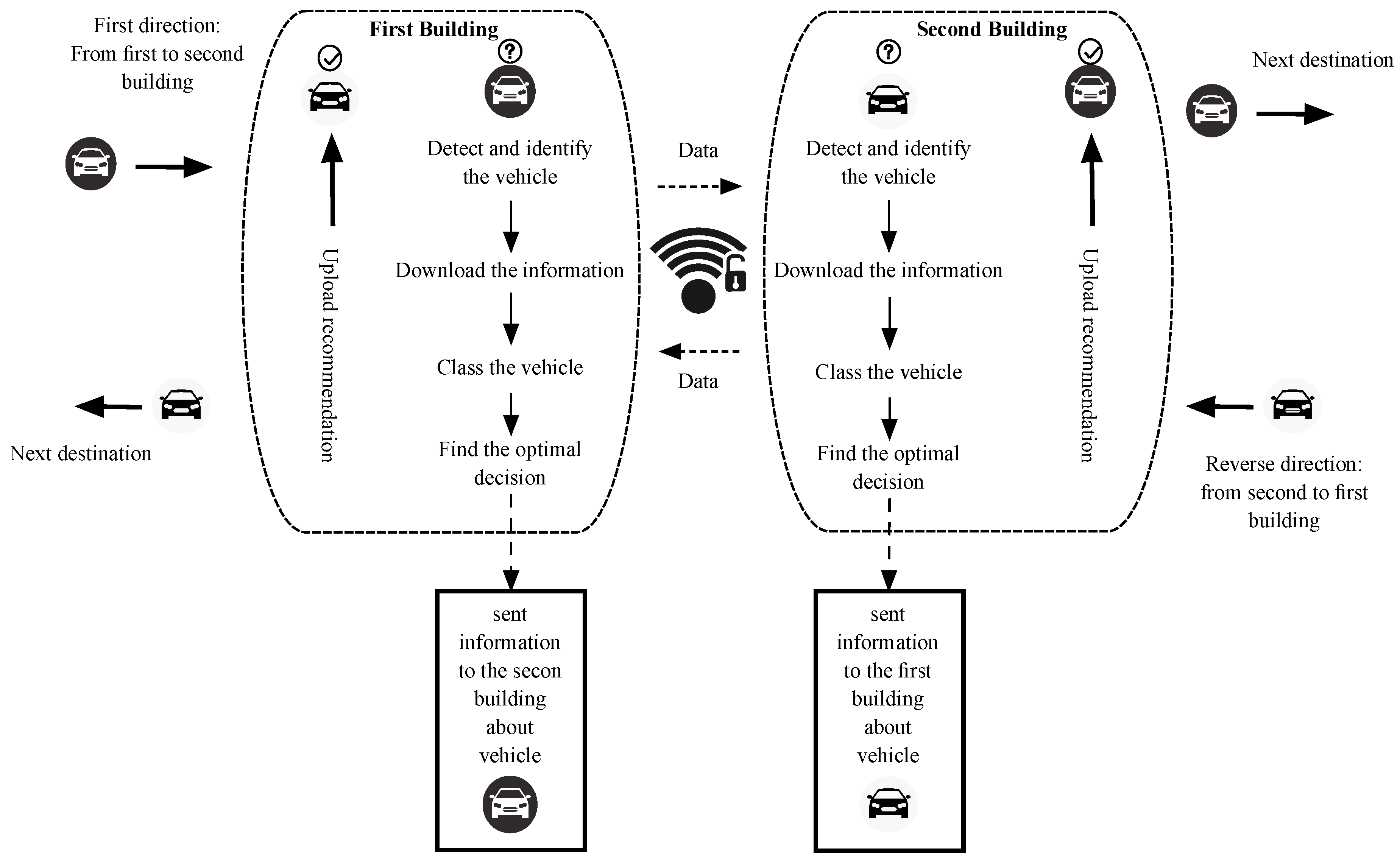
The communication protocol between two buildings is presented in Figure 5 and it is possible to generalize this principle on other houses. A specific condition must be verified for applying this protocol. This condition is related to the building position and if it is significant. Here, the presented approach is interested only in specific buildings that are close to the bends, hill climbs and in which there is a traffic jam such as schools, industries, etc...
Supposing that the white vehicle direction is from the first building “B.1” to the second “B.2”. This car is a new one in the database that is unknown to the two structures. For this vehicle trajectory, this car will be detected firstly by “B.1” and then a software application will code and identify it. Then this car will be classified into the corresponding class according to the Table 5. Finally, the software application will find the optimal energetic form for this case. The car class or category will be shared with the other buildings, that have information about the future status of the road. Then it is possible to recommend for this vehicle the best driving method in each critical road position.
Focusing on Figure 4, building “A” will detect and identify the car number “1”. Those results will be sent to the buildings “B” and “C”. Building “B” will find, from the existing database, the best driving method which is equivalent to the optimal energetic form for driving through the bend. Building “C” will recommend to this vehicle the best driving method corresponding to the hill climb. It is important to indicate that in each phase, the database will be updated according to the novel status of each car.
3.2.3. Algorithm Running Principle
The idea is transformed into a flowchart for describing the principle of this concept. Figure 6, explains the idea. If the running vehicle is detected by a building “i”, this structure will ask for the vehicle parameters and information.
It is possible that this vehicle is in the database list and it is classified as before, then it is simple to find the vehicle recommendation according to the vehicle trajectory, “each building can calculate the best solution according to the road situation for each vehicle class”. Otherwise, the new vehicle will be added to the database and it will be classified. In the same time, the database will be adjusted automatically and the new optimal solution for each class will be adjusted by a specific algorithm using neural network techniques. The new solution will be also classified for each specific case and transferred to the buildings for any possible request.
3.2.4. The Principle of Vehicle Information Treatment for the Learning Phase
The amount of vehicle data will be enormous and the management of this amount of data will be difficult and needs powerful calculators. Therefore, each building will focus on its specific zone information. The principle of using vehicle info will be as it described in Figure 7. As a neural network algorithm is used for the learning phase, the data that will be used must be related to the specific zone and handled by building “B.i” and the zone before. After the learning phase, an “optimal model” reference mathematical model will be generated and it is possible to estimate the best acceleration form in the desired zone from the vehicle information before it passes the specific structure limits.
4. Results
In this part, the MatLab Simulink tool is used for showing the simulation results related to the presented work. To prove the effectiveness of this approach, six vehicles are considered in the following example. They will follow a specific road which contains three specific situations like traffic jams, bends, and a hill climb.
It is important to indicate that the efficiency level of energy recuperation, electrical motor, the used controller, the cabling used and the battery are not taken into consideration in the power traction calculation phase, and this is done for simplifying the system of equations used in this simulation.
In the results, the difference between the two cases is explained. The first case corresponds to one vehicle which does not use the energetic recommendation. The second case is for the same vehicle which accepts the energetic recommendation. The energetic recommendation indicates the best driving method which is equivalent to the optimal energetic consumption form. As explained before this recommendation will be related to the reference acceleration profile. This section will be divided into four subsections. In the first one, the classification phase results are detailed. Next, the database is presented. The next section exposes the learning phase results and shows the optimal solution for a specific class. In this final section, energetic gain according to an example of the vehicle is indicated.
4.1. Classification Problem
As mentioned in the flowchart, the first and the final step that will be executed by the algorithm is related to the vehicle classification. In this example, the support vector classification (SVC) theory is used, due to the application rapidity needed. Similar works prove the speed of SVC for a comparable application [57,58].
For this demonstration, four cars are used as mentioned in Table 6. In the same table, classification results related to each vehicle in each specific position are detailed. The classification scores were related to the first classification problem in the proposed flowchart.
All of these vehicles were classified as C1 for the three buildings, however, vehicle number four is classed in two different classes C1 and C4 and this is due to the vehicle-related battery injected power.
4.2. Database Form
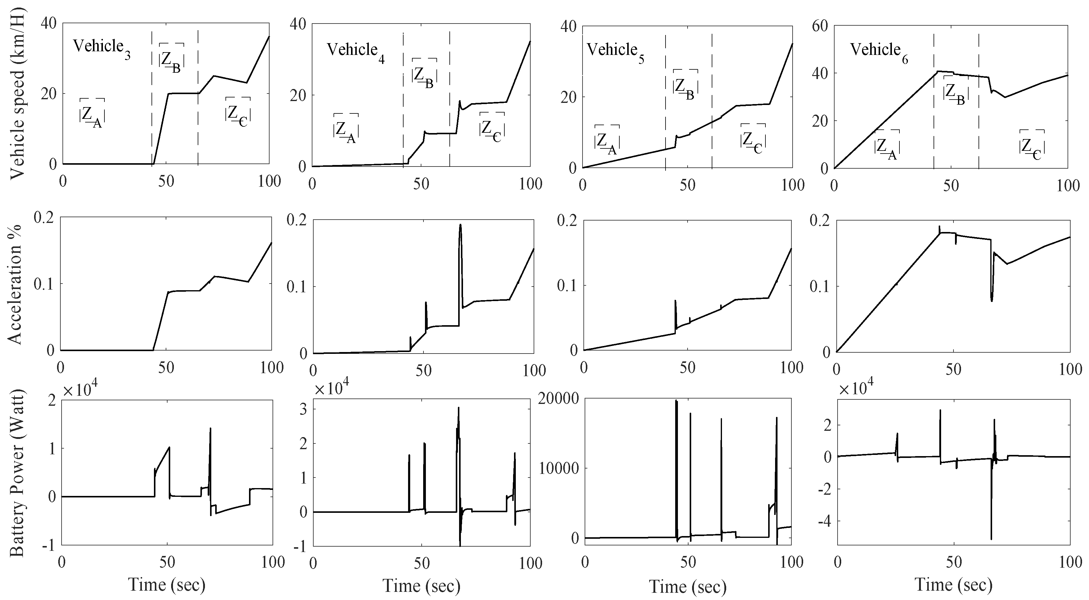
The efficiency of the learning phase cannot be guaranteed if the database used does not contain enough information about the various vehicles on the specific road. In this phase, a large database which contains information for about 100 vehicles is used. This database is built using a mathematical model of an electric vehicle and the MatLab Simulink tool. This database is obtained after various simulations tests for several car parameters as different car weights, diverse car acceleration forms, numerous battery states of charge and various speeds. Supposing that all of those vehicles were driven in the same road, from building A to C. Figure 8 shows a four vehicle example, from the database, numbered from vehicle six to vehicle three, as indicated in Figure 4. The corresponding speed, acceleration, and used battery power are as presented in Figure 8. Supposing that each vehicle has a unique driving method for three specific situations. ZA corresponds to the traffic jam situation and this part is related to building A. ZB corresponds to the bend situation and ZC corresponds to the rest of the road which contains a hill climb situation corresponding to the period of time [70 s→90 s].
As mentioned in Figure 4, supposing that each building (A, B and C), is near to each specific case (traffic jam, left bend and hill climb), the given vehicle parameters will be used for the learning phase in the next step.
4.3. Learning Phase
After classifying the four cars, the software application will update its own optimum energetic form according to this database. For this step, the neural network algorithm is used for identifying the optimum acceleration form which corresponds to the optimum energetic consumption. This step is very particular. The optimum energetic consumption can be obtained by an acceleration form close to zero. Our approach does not force the driver to drive with a specified form, but the obtained neural result will limit the acceleration form of the driver in order to obtain the best energetic form. In this situation, two different cases are obtained:
- In the first case: if the given acceleration profile is higher than the optimal one, then the acceleration profile will follow the optimal one.
- In the second case: if the given acceleration form is less than the given one, the existing form will be conserved.
The learning phase was executed using a neural network bloc composed of four neurons in the input layers, three neurons in the hidden layer and one output neuron in the output layer. The sigmoid function is used as the activation function. For this simulation phase, we have performed two steps:
- The first one is related to the database construction, in which we have built a database for more than 100 vehicles, which correspond to the maximum permitted speed in the specific zone and the minimum consumed energy. This database was obtained using a mathematical EV model on MatLab Simulink for various car weights, various acceleration profiles, various speeds and various battery initial states of charge. All of those data were used in the learning phase for obtaining an optimal mathematical model.
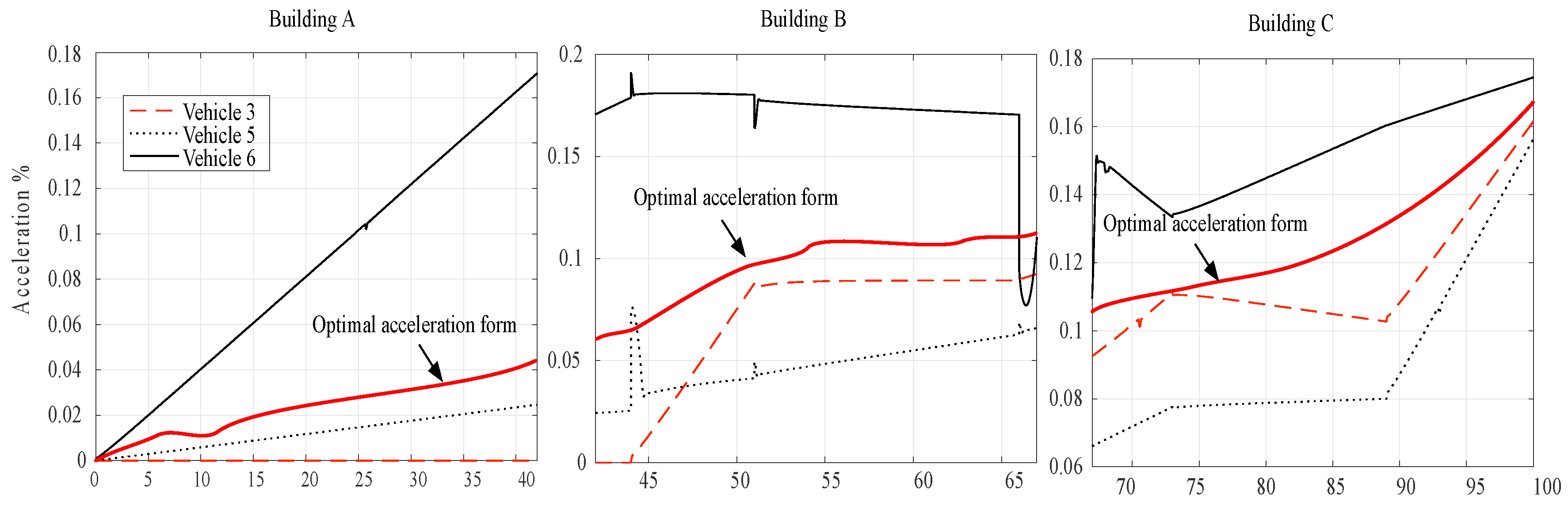
- After obtaining the optimal model, in the second phase of this simulation, we have used a random parameter of a vehicle from Class 1. Those parameters were used as the inputs of the neural network model. The related vehicle parameters, for this case are as follows: car weight = 650 kg; initial state of charge = 100%, acceleration = 0.3, required power of 12 kWh and vehicle speed = 10 km/h. According to these parameters, the optimal model was given the present acceleration form, which is the optimal solution for this car of Class 1 and for those specific parameters. Figure 9 shows the optimal acceleration form for vehicles of Class 1 and three examples of acceleration form for three vehicles in the same class from the previous database.
Each building recognizes now the optimal acceleration profile that will save energy and those results will be uploaded to the corresponding vehicle if needed.
4.4. Energetic Gain
After obtaining the optimal results, the new vehicle on the road, numbered “vehicle 2” which will pass from building “A” to building “C”, will change its acceleration according to the building recommendation and the new statistics about energy will be as presented in Table 7.
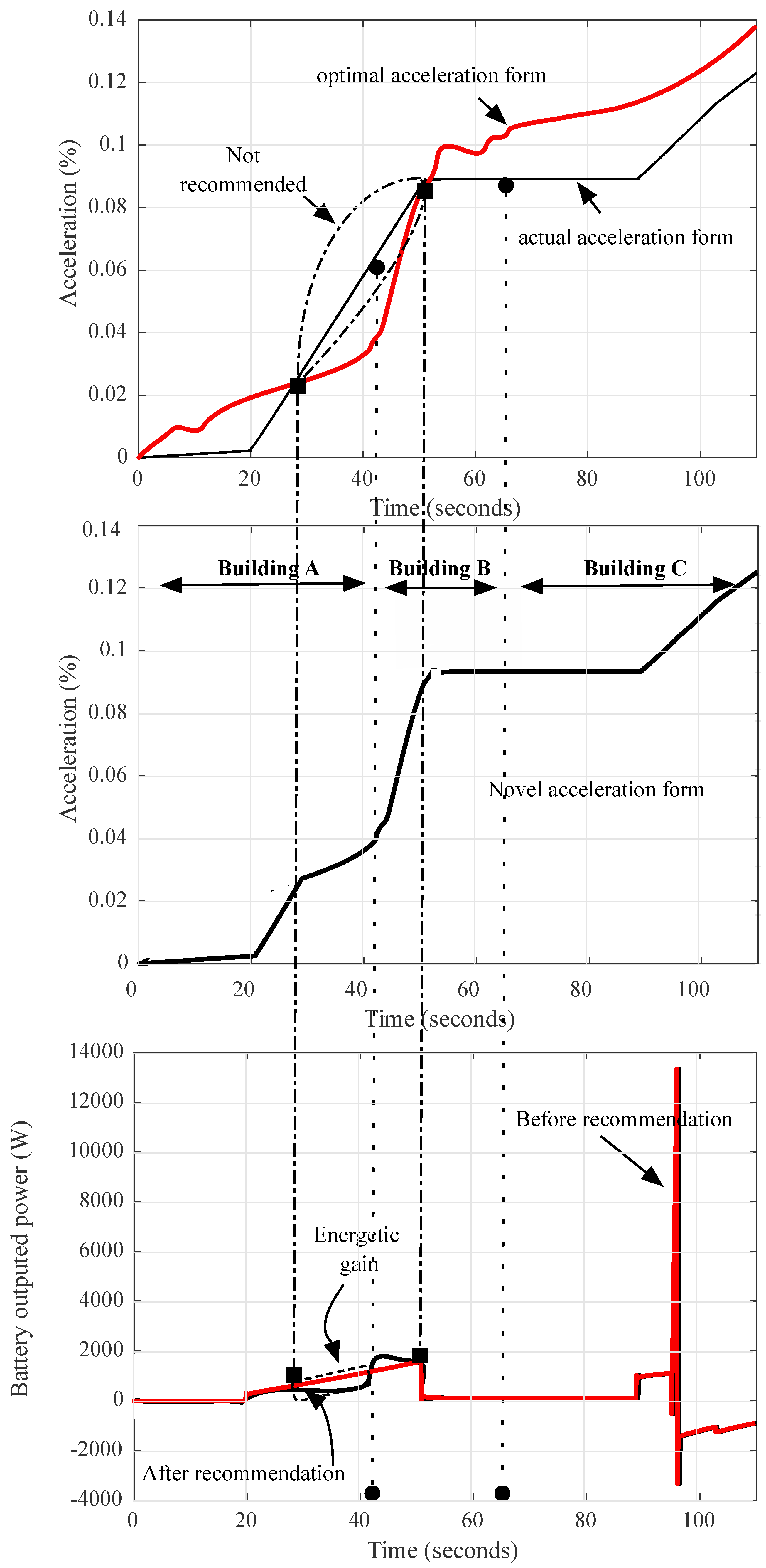
The driver was applying an acceleration profile as presented in Figure 10. If the vehicle is driven in the economic mode, each building will provide the vehicle with an optimal solution.
If the vehicle follows this recommendation and does not deviate from the optimal solution, then this energetic profile will be optimal. For this example, it is clear that the actual acceleration form is within the optimal solution range suggested by the algorithm and this is located in the part associated to building “C” and in another section associated to building “A”. Consequently, the vehicle acceleration profile is conserved in these two regions. However, the reference acceleration profile in a special part linked to building “B” is not recommended and then the new acceleration form (the optimal one) will be used. The same application occurs near building “A”. According to this situation, the energy gain will be only in the special parts related to building “B” and “A” as shown in Figure 10.
The new vehicle experience will be conserved and then the database will be updated and a new learning phase will start for updating the new optimal results. The same test will be applied to the first vehicle called vehicle “1”. However, this vehicle acceleration profile will be different from the first case. The driver drives its car with a nervous acceleration style as represented in Figure 11. In this case, the car will belong to two different classes, C1 and C2. Two different acceleration profiles will be recommended for this vehicle according to the existing data. The vehicle will transit from C1 to C2 in the building “A” region. This transition will affect the battery charge level as presented in the combined results. It is true that this form is not being recommended. It can be optimized if the classification phase will be extended to more than three categories for each data. However, according to the global energetic form, it is clear that the new form is more economical.
The provision of this approach can be clearly observed if focusing on the state of charge of the battery used. In Table 7 the SOC of each car before and after using the building recommendations are presented. It is clear that for the two cases, the novel SOC is better than the first situation.
5. Advantages and Weaknesses of this Approach
The basic advantages of the proposed approach are seen in the results obtained. Effectively an energetic gain will be guaranteed with this method. However, the importance of this approach is not related only to the magnitude of the energy savings. The most important advantage is related to the approach principle, in which the solution is obtained from the collaboration of vehicles and buildings. Effectively all vehicles can collaborate in optimizing the energy use. This facilitates the optimization problem inside the car and provides an efficient reference output. This is not the case for an autonomous electric vehicle, where the power optimization method will be related only to the vehicle itself. This proposed principle is different as exposed in previous solutions, where each car seeks to optimize its energy consumption profile. The other contribution in this work is related to the proposed algorithm which uses the learning phase for building an optimal model for generating an optimal output factor, which helps saving energy inside the vehicle. This approach can be used even there are no buildings. Effectively, since the used road is instrumented with the needed equipment, the proposed approach can be applied and a possible standardization of this optimization algorithm can make this approach novel.
Another advantage characterizes this approach, and it is related to the problem of updating and maintenance of the energy management program or equipment within the vehicle. Indeed if each vehicle is responsible for its own energy optimization, each vehicle certainly requires maintenance and program updating. However, with this approach the energy management program will be centralized in specific points which facilitates the maintenance and software updating, especially in relation to the energy management problem. This saves time and money.
Based on several related works, Table 8 lists the proposed approach’s advantages and compares them with the online and offline scheduling algorithms, presented in [59], the optimization-based algorithm presented in [60] and the rules-based algorithm described in [61].
The evaluation step is based on four important factors, such as the total energetic gain on the road per day, the needed calculation time inside the vehicle, and the response time of the vehicle, te system programming complexity and the total cost of the power management approach used. This final point is the critical point for this approach. Effectively, the total cost for installing, sensors, camera, the network system, will be high. However, we can estimate that the total saved energy per day will be the highest with our approach.
According to the obtained results, the proposed approach can improve the energy level of the battery and therefore the vehicle autonomy. However, this advantage cannot negate the drawbacks of this approach. Effectively, to perform such an application, high power calculators installed in each building and in vehicles are needed. Communication problems can happen between the two systems and a redundant backup system is required for flawless operation. Finally, a standardization on vehicle’s software is needed, so more vehicles can be used and more specific energetic data can be collected.
6. Conclusions and Future Work
Based on new concepts and technologies, the efficiency of smart cities has become undeniable. In relation to this, efficient transport systems have become compulsory and this is always related to energy problems. Effectively, increasing electrical vehicle autonomy is always a serious objective. Therefore, the studies for resolving this weakness have not stopped. In this context, this study presented a novel approach for managing the power inside the electric vehicle, in order to increase the vehicle autonomy. The main objective is related to the electric vehicle power optimization by controlling the quantity of power used in critical regions, based on vehicle to building wireless communication.
The exchange of information and cooperation between vehicles and buildings makes this power management approach unique. The problem of power management is moved outside the vehicle to the buildings and this presents the main contribution of this approach. This problem is resolved by a particular flowchart which uses two specific algorithms related to the artificial intelligence principle and space vector classification. Simulations using the MatLab tool proved that energy can be saved using this novel power management method, so the vehicle autonomy can be ameliorated.
The electric vehicle is an evolving field and the new technology can reform the power management methods. Based on the proposed approach, the flowchart used can be upgraded for a possible standardization to all vehicle models such as hybrid and all electric vehicles. Also, the possibility of extending this approach outside the city presents a serious challenge. Based on these future extensions, the required energy can be estimated and calculated beforehand, so the battery recharging phase will be more efficient, especially for wireless recharging systems on the highway/road. A novel vision for an inductive power transmission system even for cars in motion will be defined. In the other hand, the smart city concept can benefit more from the efficiency of the proposed approach. As an example, more solutions for the traffic problems in big cities will be possible. Effectively, it is possible to predict the period of a traffic jam, from the existing database, in relation to the building positions. Other benefits can be related to this approach and this is will be identified and explained in our future endeavors.
Author Contributions
F.A. did theoretical analysis, system implementation, simulations test and wrote the first original and the last version of the draft paper. The proposed approach was discussed with M.C., who verified also the first paper draft.
Funding
This research received no external funding.
Acknowledgments
This work presents an extended version of a selected paper in ISAECT 2018 conference.
Conflicts of Interest
The authors declare no conflict of interest.
Acronym List
| fr | The rolling resistance |
| Mv | Mass of the vehicle |
| g | Gravitational acceleration |
| wm | Motor speed |
| γm | Motor efficiency |
| θ | Road grade |
| Cd | Drag coefficient |
| ρ | Air density |
| Av | Frontal area of the vehicle |
| Qc | Battery capacity |
| Voc | Battery voltage |
| Vv | Vehicle speed |
| mvo | Vehicle mass |
| mba | Battery mass |
| mem | Electric motor mass |
| Ibatt | Battery current |
| Rbatt | Battery resistance |
| Cm | Motor torque |
References
- Pérez-Chacón, R.; Luna-Romera, J.; Troncoso, A.; Martínez-Álvarez, F.; Riquelme, J.; Pérez-Chacón, R.; Luna-Romera, J.M.; Troncoso, A.; Martínez-Álvarez, F.; Riquelme, J.C. Big Data Analytics for Discovering Electricity Consumption Patterns in Smart Cities. Energies 2018, 11, 683. [Google Scholar] [CrossRef]
- Tie, S.S.F.; Tan, C.W.C. A review of energy sources and energy management system in electric vehicles. Renew. Sustain. Energy Rev. 2013, 20, 82–102. [Google Scholar] [CrossRef]
- Ye, B.; Jiang, J.; Miao, L.; Yang, P.; Li, J.; Shen, B. Feasibility Study of a Solar-Powered Electric Vehicle Charging Station Model. Energies 2015, 8, 13265–13283. [Google Scholar] [CrossRef] [Green Version]
- Panagiotis, K.; Lambros, E. Electricity Distribution Intelligent Solutions for Electricity Transmission and Distribution Networks; Energy Net.; Springer: Berlin/Heidelberg, Germany, 2016; ISBN 978-3-662-49432-5. [Google Scholar]
- Vatu, R.; Ceaki, O.; Golovanov, N.; Porumb, R.; Seritan, G. Analysis of storage technologies within smart grid framework. In Proceedings of the 2014 49th International Universities Power Engineering Conference (UPEC), Cluj-Napoca, Romania, 2–5 September 2014; pp. 1–5. [Google Scholar]
- Monteiro, V.; Pinto, J.G.; Afonso, J.L. Operation Modes for the Electric Vehicle in Smart Grids and Smart Homes: Present and Proposed Modes. IEEE Trans. Veh. Technol. 2016, 65, 1007–1020. [Google Scholar] [CrossRef] [Green Version]
- Rioux, S.-P. Statistiques on Electical Vehicle in Canada. Available online: https://www.aveq.ca/actualiteacutes/category/statistiques (accessed on 30 December 2018).
- Karbowski, D.; Sokolov, V.; Jongryeol, J. Fuel Saving Potential of Optimal Route-Based Control for Plug-in Hybrid Electric Vehicle. IFAC Pap. Online 2016, 49, 128–133. [Google Scholar] [CrossRef]
- Hawkins, T.R.; Gausen, O.M.; Stroemman, A.H. Environmental impacts of hybrid and electric vehicles—A review. Int. J. Life Cycle Assess. 2012, 17, 997–1014. [Google Scholar] [CrossRef]
- Longest-Range Electric Vehicles for 2018. Available online: https://www.motor1.com/features/228379/longest-range-evs/2850064/ (accessed on 16 October 2018).
- Khan Ali, L.; Badjate, Z.S.; Kshirsagar, R.V. Review on Energy Management System for Hybrid Vehicle. Int. J. Sci. Technol. Eng. 2016, 2, 95–98. [Google Scholar]
- Zhang, S.; Xiong, R. Adaptive energy management of a plug-in hybrid electric vehicle based on driving pattern recognition and dynamic programming. Appl. Energy 2015, 155, 68–78. [Google Scholar] [CrossRef]
- Mahmoudi, C.; Flah, A.; Sbita, L. Prototype design of a compact plug-in solar electric vehicle application for smart power management architecture. In Proceedings of the International Conference on Green Energy and Conversion Systems (GECS), Hammamet, Tunisia, 23–25 March 2017. [Google Scholar]
- Shetty, S.S.; Karabasoglu, O. Regenerative Braking Control Strategy for Hybrid and Electric Vehicles Using Artificial Neural Networks. In Proceedings of the 15th International Conference on Engineering Applications of Neural Networks (EANN 2014), Sofia, Bulgaria, 5–7 September 2014; Mladenov, V., Jayne, C., Iliadis, L., Eds.; Springer International Publishing: Cham, Switzerland, 2014; pp. 103–112, ISBN 978-3-319-11071-4. [Google Scholar]
- Itani, K.; De Bernardinis, A.; Zoubir, K.; Jammal, A. Extreme conditions regenerative braking modeling, control, and simulation of a hybrid energy storage system for an electric vehicle. IEEE Trans. Transp. Electrif. 2016, 7782, 1–16. [Google Scholar] [CrossRef]
- Werachet, K.; Heinz, Z. Wirless power charging on electric vehicles. In Proceedings of the International Electrical Engineering Congress, chonburi, Thailand, 16 October 2014; pp. 6–9. [Google Scholar]
- Flah, A. Internal Fuzzy Hybrid Charger System for a Hybrid Electrical Vehicle. ASME J. Energy Resour. Technol. 2017, 140, 12003–12008. [Google Scholar]
- Xi, L.; Zhang, X.; Sun, C.; Wang, Z.; Hou, X.; Zhang, J. Intelligent Energy Management Control for Extended Range Electric Vehicles Based on Dynamic Programming and Neural Network. Energies 2017, 10, 1871. [Google Scholar] [CrossRef]
- Lin, Y.-H.; Hu, Y.-C. Electrical Energy Management Based on a Hybrid Artificial Neural Network-Particle Swarm Optimization-Integrated Two-Stage Non-Intrusive Load Monitoring Process in Smart Homes. Processes 2018, 6, 236. [Google Scholar] [CrossRef]
- Gaoua, Y. On-Line HEV Energy Management Using a Fuzzy Logic. In Proceedings of the 12th International Conference on Environment and Electrical Engineering (EEEIC), Wroclaw, Poland, 5–8 May 2013; p. 6. [Google Scholar]
- Sakhdari, B.; Azad, N. An Optimal Energy Management System for Battery Electric Vehicles A. IFAC Pap. Online 2015, 48, 86–92. [Google Scholar] [CrossRef]
- Gruosso, G.; Milano, P.; Elettronica, D.; Bioingegneria, I. Optimization and management of energy power flow in hybrid electrical vehicles. In Proceedings of the 5th IET Hybrid and Electric Vehicles Conference (HEVC 2014), London, UK, 5–6 November 2014; pp. 1–5. [Google Scholar]
- Jha, S.K.; Yadav, A.K.; Gaur, P. Power management for electric vehicle with PID and Fuzzy logic controllers. In Proceedings of the 2017 International conference of Electronics, Communication and Aerospace Technology (ICECA), Coimbatore, India, 20–22 April 2017; Volume 2, pp. 56–61. [Google Scholar]
- Xie, S.; Hu, X.; Qi, S.; Lang, K. An artificial neural network-enhanced energy management strategy for plug-in hybrid electric vehicles. Energy 2018, 163, 837–848. [Google Scholar] [CrossRef]
- Panday, A.; Bansal, H.O.H. A Review of Optimal Energy Management Strategies for Hybrid Electric Vehicle. Int. J. Veh. Technol. 2014, 2014, 19. [Google Scholar] [CrossRef]
- Biondi, E.; Boldrini, C.; Bruno, R. Optimal charging of electric vehicle fleets for a car sharing system with power sharing. In Proceedings of the 2016 IEEE International Energy Conference (ENERGYCON), Leuven, Belgium, 4–8 April 2016. [Google Scholar]
- Mohd, S.; Zulkifli, S.A.; Rangkuti, R.G.A.; Ovinis, M.; Saad, N. Electric Vehicle Energy Management System using National Instruments’ CompactRIO and LabVIEW. In Proceedings of the IEEE International Conference on Smart Instrumentation, Measurement and Applications (ICSIMA), Kuala Lumpur, Malaysia, 26–27 November 2013; pp. 88–93. [Google Scholar]
- Ejaz, W.; Anpalagan, A. Internet of Things Enabled Electric Vehicles in Smart Cities. In Internet of Things for Smart Cities; Springer: Cham, Switzerland, 2019; pp. 39–46. ISBN 978-3-319-95036-5. [Google Scholar]
- Calvillo, C.F.; Sánchez-Miralles, A.; Villar, J.; Martín, F. Impact of EV penetration in the interconnected urban environment of a smart city. Energy 2017, 141, 2218–2233. [Google Scholar] [CrossRef]
- Talari, S.; Shafie-Khah, M.; Siano, P.; Loia, V.; Tommasetti, A.; Catalão, J.P.S. A review of smart cities based on the internet of things concept. Energies 2017, 10, 421. [Google Scholar] [CrossRef]
- Mahizhnan, A. Smart Cities; Springer international: London, UK, 1999; Volume 16, ISBN 978-3-319-76668-3. [Google Scholar]
- Shuai, W.; Maillé, P.; Pelov, A. Charging Electric Vehicles in the Smart City: A Survey of Economy-Driven Approaches. IEEE Trans. Intell. Transp. Syst. 2016, 17, 2089–2106. [Google Scholar] [CrossRef]
- Ahmed, M.A.; Kim, Y.-C. Energy Trading with Electric Vehicles in Smart Campus Parking Lots. Appl. Sci. 2018, 8, 1749. [Google Scholar] [CrossRef]
- Lund, H.; Østergaard, P.A.; Connolly, D.; Mathiesen, B.V. Smart energy and smart energy systems. Energy 2017, 137, 556–565. [Google Scholar] [CrossRef]
- Nikitas, A.; Kougias, I.; Alyavina, E.; Njoya Tchouamou, E. How Can Autonomous and Connected Vehicles, Electromobility, BRT, Hyperloop, Shared Use Mobility and Mobility-As-A-Service Shape Transport Futures for the Context of Smart Cities? Urban Sci. 2017, 1, 36. [Google Scholar] [CrossRef]
- Barbato, A.; Bolchini, C.; Geronazzo, A.; Quintarelli, E.; Palamarciuc, A.; Pitì, A.; Rottondi, C.; Verticale, G.; Barbato, A.; Bolchini, C.; et al. Energy Optimization and Management of Demand Response Interactions in a Smart Campus. Energies 2016, 9, 398. [Google Scholar] [CrossRef]
- Li, B.; Kisacikoglu, M.C.; Liu, C.; Singh, N.; Erol-kantarci, M. Big Data Analytics for Electric Vehicle Integration in Green Smart Cities. IEEE Commun. Mag. 2017, 55, 19–25. [Google Scholar] [CrossRef]
- Lu, N.; Cheng, N.; Zhang, N.; Shen, X.; Mark, J.W. Connected vehicles: Solutions and challenges. IEEE Internet Things J. 2014, 1, 289–299. [Google Scholar] [CrossRef]
- Liu, C.; Chau, K.T.; Wu, D.; Gao, S. Opportunities and challenges of vehicle-to-home, vehicle-to-vehicle, and vehicle-to-grid technologies. Proc. IEEE 2013, 101, 2409–2427. [Google Scholar] [CrossRef]
- Fleming, W.J. A review of new automotive sensors. IEEE Sens. J. 2008, 8, 1900–1921. [Google Scholar] [CrossRef]
- Paidi, V.; Fleyeh, H.; Håkansson, J.; Nyberg, R.G. Smart parking sensors, technologies and applications for open parking lots: A review. IET Intell. Transp. Syst. 2018, 12, 735–741. [Google Scholar] [CrossRef]
- Chan, C.C.; Chau, K.T. Modern Electric Vehicle Technology; Monographs in Electrical and Engineering; Oxford University Press: Oxford, UK, 2001; ISBN 9780198504160. [Google Scholar]
- Helmers, E.; Marx, P. Electric cars: Technical characteristics and environmental impacts. Environ. Sci. Eur. 2012, 24, 14. [Google Scholar] [CrossRef]
- Azahan, N.A.; Jamian, J.; Noorden, Z. Analysis of relationship between acceleration and battery state of charging in electric vehicle. In Proceedings of the IEEE International Conference on Power and Energy, Melaka, Malaysia, 28–29 November 2016; pp. 150–154. [Google Scholar]
- Xiong, R.; Cao, J.; Yu, Q.; He, H.; Sun, F. Critical Review on the Battery State of Charge Estimation Methods for Electric Vehicles. IEEE Access 2018, 6, 1832–1843. [Google Scholar] [CrossRef]
- Young, K.; Wang, C.; Wang, L.Y.; Strunz, K. Electric Vehicle Battery Technologies; Springer International Publishing: New York, NY, USA, 2013; ISBN 9781461401346. [Google Scholar]
- Calvillo, C.F.; Sánchez-Miralles, A.; Villar, J. Energy management and planning in smart cities Energy management and planning in smart cities. Renew. Sustain. Energy Rev. 2016, 55, 273–287. [Google Scholar] [CrossRef]
- Monitoring, S.; Chui, K.T.; Lytras, M.D. Energy Sustainability in Smart Cities: Artificial intelligence, smart monitoring, and optimization of energy consumption. Energies 2018, 11, 2869. [Google Scholar]
- Menouar, H.; Güvenc, I.; Akkaya, K.; Uluagac, A.S.; Kadri, A.; Tuncer, A. UAV-Enabled Intelligent Transportation Systems for the Smart City: Applications and Challenges. IEEE Commun. Mag. 2017, 55, 22–28. [Google Scholar] [CrossRef]
- Letaief, K.B. To Smart City: Public Safety Network Design for Emergency. IEEE Access 2018, 6, 1451–1460. [Google Scholar]
- Grofils, S. 10 Conseils Pour Éco-Conduire. Available online: http://www.ecoconso.be/fr/10-conseils-d-eco-conduite (accessed on 2 January 2019).
- Bossicart, D. Les dix commandements pour conduire de manière économique et écologique. Available online: http://www.abcourtage.lu/les-dix-commandements-pour-conduire-de-maniere-economique-et-ecologique/ (accessed on 2 January 2019).
- Pascal, N. En 2040, les véhicules électriques en France consommeront plus que le Danemark; le réseau peut-il tenir? Available online: https://selectra.info/energie/actualites/insolite/consommation-vehicules-electriques-france-2040 (accessed on 1 January 2019).
- Berjoza, D.; Jurgena, I. Effects of change in the weight of electric vehicles on their performance characteristics. Agron. Res. 2017, 15, 952–963. [Google Scholar]
- David, H. How Does EPA Estimate Electric Car Driving Range? Available online: https://greentransportation.info/ev-charging/range-confidence/chap5-ev-range/epa-estimates.html (accessed on 1 January 2019).
- Canada, G. Véhicules électriques de l’année modèle 2019. Available online: https://www.rncan.gc.ca/energie/efficacite/transports/21412 (accessed on 8 February 2019).
- Innerwinkler, P.; Ebner, W.; Stolz, M. Support Vector Machines for Determination of an Operational Strategy for Hybrid Electric Vehicles. In Proceedings of the 2015 23rd Mediterranean Conference on Control and Automation (MED), Torremolinos, Spain, 16–19 June 2015; pp. 709–714. [Google Scholar]
- Niu, W.; Feng, Z.; Feng, B.; Min, Y.; Cheng, C. Neural Network, Extreme Learning Machine, and Support Vector Machine in Deriving Operation Rule of Hydropower Reservoir. Water 2019, 11, 88. [Google Scholar] [CrossRef]
- Rigas, E.S.; Ramchurn, S.D.; Bassiliades, N. Algorithms for electric vehicle scheduling in large-scale mobility-on-demand schemes. Artif. Intell. 2018, 262, 248–278. [Google Scholar] [CrossRef]
- Zhou, J.; Li, M. Optimization based control strategy for large hybrid electric vehicles. SAE Technical Paper 2018. No. 2018-01-1030. [Google Scholar] [CrossRef]
- Banvait, H.; Anwar, S.; Chen, Y. A Rule-Based Energy Management Strategy for Plug-in Hybrid Electric Vehicle (PHEV). In Proceedings of the American Control Conference, St. Louis, MO, USA, 10–12 June 2009; pp. 3938–3943. [Google Scholar]
Figure 1.
Conventional information sharing between a smart city and an EV.

Figure 2.
EV and its basic components.

Figure 3.
Three road signs which signify that a high acceleration is useless.

Figure 4.
Three different cases with a useless high acceleration on a road.

Figure 5.
The communication protocol between buildings about changing information related to the vehicles.
Figure 5.
The communication protocol between buildings about changing information related to the vehicles.

Figure 6.
Flowchart of the proposed algorithm.

Figure 7.
The principle of the learning phase and vehicle zone recommendation.

Figure 8.
Related speed, acceleration form, and the corresponding battery outputted power for the four cars.
Figure 8.
Related speed, acceleration form, and the corresponding battery outputted power for the four cars.

Figure 9.
Actual and optimal acceleration profiles for a Class C1 vehicle in the three different zones.
Figure 9.
Actual and optimal acceleration profiles for a Class C1 vehicle in the three different zones.

Figure 10.
Actual, optimal and novel acceleration form for the vehicle “2” and the related energetic gain.
Figure 10.
Actual, optimal and novel acceleration form for the vehicle “2” and the related energetic gain.

Figure 11.
Actual, optimal and novel acceleration form for the vehicle “1” and the according injected battery power.
Figure 11.
Actual, optimal and novel acceleration form for the vehicle “1” and the according injected battery power.


Table 1.
Related autonomy and battery power for various cars types [10].
Table 1.
Related autonomy and battery power for various cars types [10].
| EV Model | Autonomy | Battery | [kW/h]/100 km |
|---|---|---|---|
| Tesla * | 542 km | 85 kWh | 20.9 |
| Chevrolet | 382 km | 16 kWh | 23.5 |
| Hyundai | 200 km | 28 kWh | 17.2 |
| Ford Focus | 185 km | 33.5 kWh | 18.2 |
* The best EV performance in 2018.
Table 2.
Classification and importance of using V2V, V2B, and V2R.
| Vehicles Communication Type | Complexity of the System Installation | Cost of the Installation | Availability of Electric Power | Communication Zone | Security of Equipment |
|---|---|---|---|---|---|
| V2V | L | H | H | L | M |
| V2R | H | H | M | H | L |
| V2B | L | L | H | H | H |
H: High; M: Medium, L: Low.
Table 3.
Propulsion power of an example of a vehicle of 500 Kg with two different acceleration ratios.
Table 3.
Propulsion power of an example of a vehicle of 500 Kg with two different acceleration ratios.
| Vehicle Mass | 500 kg | 500 kg |
| Acceleration 0 to 70 Km/h at | 7 m/s2 | 3.5 m/s2 |
| Air density | 1,225 kg/m3 | 1,225 kg/m3 |
| Wind speed | 0 m/s | 0 m/s |
| Rolling resistance coefficient | 0 | 0 |
| Aerodynamic drag coefficient | 0.3 | 0.3 |
| Average needed power | 47.3 kW | 43.1 kW |
| Initial state of charge | 100% | 100% |
| Final state of charge | 99.97% | 99.99% |
Table 4.
Maximum speeds and acceleration values in various road situations in a city.
| Situation | Acceleration Ratio | Speed Value |
|---|---|---|
| Traffic jam | 3 m/s2 | 15 km/h |
| Bends of 30° | 2 m/s2 | 60 km/h |
| Bends of 60° | 2 m/s2 | 40 km/h |
| Hill climb of 20% | 1 m/s2 | 30 km/h |
| Hill climb of 10% | 2 m/s2 | 40 km/h |
| Data Classification | C1 | C2 | C3 | C4 | C5 | C6 … C76 | C77 | C78 | C79 | C80 | C81 | ||
| Acc % | Acc1 | [0 … 0.3] [0.70 … 1] | |||||||||||
| Acc2 | |||||||||||||
| Acc3 | |||||||||||||
| P (kW) | P1 | <20 20 < … <50 >50 | |||||||||||
| P2 | |||||||||||||
| P3 | |||||||||||||
| Speed (Km/h) | V1 | <40 40< … <70 >70 | |||||||||||
| V2 | |||||||||||||
| V3 | |||||||||||||
| Weight (Kg) | W1 | <600 >1000 | |||||||||||
| W2 | |||||||||||||
| W3 | |||||||||||||
Table 6.
Used cars parameters and related classification results.
| SVC related data and classes | Vehicle 3 | Vehicle 4 | Vehicle 5 | Vehicle 6 | |
|---|---|---|---|---|---|
| Used data for classification | Weight (kg) | 600 | 550 | 580 | 600 |
| speed | In Figure 8 | ||||
| Power | In Figure 8 | ||||
| Acceleration | In Figure 8 | ||||
| SVC-class according to each building | B1 | C1 | C1 | C1 | C1 |
| B2 | C1 | C4 | C1 | C1 | |
| B3 | C1 | C1 | C1 | C1 | |
Table 7.
SOC before and after the recommendation.
| Vehicles number | Initial SOC | Actual SOC | |
|---|---|---|---|
| Before Recommendation | After Recommendation | ||
| Vehicle 2 | 100% | 99.1% | 99.3% |
| Vehicle 1 | 100% | 97.9% | 97.5% |
Table 8.
Our approach faces the known optimization methods.
| Optimization Methods | Time Calculation in the Vehicle | Energetic Gain per Day | Algorithm Complexity Inside the Vehicle | Total Cost of the Power Management Principle |
|---|---|---|---|---|
| Proposed approach: | L | H | L | H |
| Offline scheduling algorithm | H | L | L | L |
| Online scheduling algorithm | H | M | M | L |
| Rule-based algorithm | M | L | L | L |
| Optimization-based algorithm | H | M | L | L |
H: High; M: Medium, L: Low.
© 2019 by the authors. Licensee MDPI, Basel, Switzerland. This article is an open access article distributed under the terms and conditions of the Creative Commons Attribution (CC BY) license (http://creativecommons.org/licenses/by/4.0/).
Share and Cite
MDPI and ACS Style
Aymen, F.; Mahmoudi, C. A Novel Energy Optimization Approach for Electrical Vehicles in a Smart City. Energies 2019, 12, 929. https://doi.org/10.3390/en12050929
AMA Style
Aymen F, Mahmoudi C. A Novel Energy Optimization Approach for Electrical Vehicles in a Smart City. Energies. 2019; 12(5):929. https://doi.org/10.3390/en12050929
Chicago/Turabian StyleAymen, Flah, and Chokri Mahmoudi. 2019. "A Novel Energy Optimization Approach for Electrical Vehicles in a Smart City" Energies 12, no. 5: 929. https://doi.org/10.3390/en12050929
Note that from the first issue of 2016, this journal uses article numbers instead of page numbers. See further details here.