Review

Review on Building-Integrated Photovoltaics Electrical System Requirements and Module-Integrated Converter Recommendations

by
Simon Ravyts
1,2,*,
Mauricio Dalla Vecchia
1,2,
Giel Van den Broeck
1,2 and
Johan Driesen
1,2
1
Department of Electrical Engineering, ESAT, KU Leuven, Kasteelpark Arenberg 10, 3001 Leuven, Belgium
2
EnergyVille, Thor Park 8310, 3600 Genk, Belgium
*
Author to whom correspondence should be addressed.
Energies 2019, 12(8), 1532; https://doi.org/10.3390/en12081532
Submission received: 26 March 2019 / Revised: 16 April 2019 / Accepted: 17 April 2019 / Published: 23 April 2019
(This article belongs to the Special Issue Alternative Energy Systems in Buildings)

Abstract

:
Since building-integrated photovoltaic (BIPV) modules are typically installed during, not after, the construction phase, BIPVs have a profound impact compared to conventional building-applied photovoltaics on the electrical installation and construction planning of a building. As the cost of BIPV modules decreases over time, the impact of electrical system architecture and converters will become more prevalent in the overall cost of the system. This manuscript provides an overview of potential BIPV electrical architectures. System-level criteria for BIPV installations are established, thus providing a reference framework to compare electrical architectures. To achieve modularity and to minimize engineering costs, module-level DC/DC converters preinstalled in the BIPV module turned out to be the best solution. The second part of this paper establishes converter-level requirements, derived and related to the BIPV system. These include measures to increase the converter fault tolerance for extended availability and to ensure essential safety features.

1. Introduction

1.1. Motivation

Building-integrated photovoltaic (BIPV) systems consist of solar photovoltaic (PV) cells and modules that are integrated in the building envelope as part of the building structure, replacing conventional building materials [1,2]. BIPV is now being proposed as an economically viable solution to the increasing demand for renewable electricity generation, since the relatively minor added cost of PV cells to the overall building component’s cost results in conceivable payback times [3,4]. Furthermore, developments in thin-film PV technology reduce the costs of adding PV to structural elements even further [5,6].
The use of BIPV is encouraged by the European Strategic Energy Technology (SET) Plan [7] and the European Energy Performance of Buildings Directive (EPBD) [8]. The EPBD requires that all new buildings in the 28 member states are near Zero Energy Buildings (NZEB) from 2020 on. The implementation can be a combined result of reducing the energy demand and increasing the energy generation on site. In high-rise buildings, the amount of roof surface where PV panels can be placed might be unsufficient to cover the demand of the building. Placing PV in the façades offers a solution to this [9,10]. A high amount of research is conducted towards the different aspects of BIPV, such as BIPV Thermal (BIPVT) installations [11,12,13], a life-cycle analysis of BIPV installations [14,15], ab optimal design to match the electric loads in NZEB [16], the refurbishment and renovation of older buildings using BIPV [17,18,19], the thermal impact on the building [20,21,22,23], novel PV materials for use in BIPV products [24,25,26,27], the role of Building Information Management (BIM) in the design of new buildings with BIPV [28,29,30], and specific case studies [31,32,33,34,35]. This manuscript focuses on the electrical installation aspects of façade BIPV modules where a high degree of modularity is envisioned. At first sight, the electrical installation of BIPV systems does not seem to differ from building-applied photovoltaics (BAPV). This paper will highlight that the expectations and boundary conditions are different and lead to specific requirements for the design of new power electronics converters.
A wide variety of BIPV modules is commercially available on the market [3,36,37,38,39]. In general, two classes of BIPV modules are distinguished, namely roofing BIPV modules [40] and façade BIPV modules [3,41]. The first category consists of PV modules that are part of the roof structure of a building, comprising in-roof systems, full roof solutions, and solar tiles. The second category further distinguishes cold and warm façades, depending on whether the BIPV modules contain a ventilated air gap or not. Additionally, accessories exist such as parapets, balconies, and solar shadings not belonging directly to the building skin [42].
More than BAPV systems, BIPV systems have a profound impact on the electrical installation of the building and on the planning of the construction works, as the BIPV modules are installed during the construction phase and not fitted after construction has completed. Hence, the way in which the BIPV modules are interconnected and converter-interfaced is important to consider in order to minimize the additional required installation time and system engineering effort. In that regard, module-level converters (MLCs) that are factory preinstalled in the BIPV modules are promising [43]. Their main advantage of modularity prevails over the use of conventional string-level inverters, which are usually praised for their lower system cost [44]. Furthermore, adopting a DC instead of an AC distribution architecture simplifies the design of the module-level converters, resulting in an increased compactness, efficiency, and reliability [45,46]. Apart from that, as the cost of BIPV modules reduces further over time, the impact of the electrical installation architecture and the converters becomes more prevalent in the overall cost of the system.
Besides modularity, module-level converters reduce the impact of partial shading and are capable of supporting a wide variety of BIPV modules and associated electrical specifications [36,47,48,49]. Especially partial shading, leading to different I-V characteristics and maximum power points (MPP) of neighbouring modules is more prevalent in BIPV systems as compared to BAPV [50,51,52,53].
However, preinstalling module-level converters in BIPV modules leads to higher required levels of fault tolerance of the converters as it is undesirable or practically infeasible to replace the converter after an internal failure. Therefore, this paper discusses the possible failure modes of module-level converters, including its causes, consequences, and detection methods, and introduces techniques to ensure the fail-safe operation of the module-level converter if necessary. Additionally, the need for non-isolated or isolated module-level converters will be addressed.

1.2. Research Questions and Objectives

The research questions in this paper are (1) Given the difference with BAPV, what are the specific requirements of a BIPV electrical installation? General ideas will be translated to concrete evaluation points that serve as Key Performance Indicators (KPIs); (2) What are the advantages of Low-Voltage DC (LVDC) grids compared to traditional AC grids to electrically interconnect BIPV modules?; (3) Can the electrical requirements be translated to practical converter design recommendations?; and (4) What is the impact of the LVDC grid configuration (low resistance grounded—TN-S or high resistance grounded—IT) on the reliability and fault-tolerance of the system?

1.3. Paper Structure

This paper is organized as follows. The first section presented an introduction, including the motivation for the research and the specific research questions. The second section addresses system-level criteria for BIPV installations. A comparison between the different electrical architectures is given in section three. The fourth section will translate the system-level criteria into specific converter requirements and discuss relevant fault-tolerance and safety aspects more in-depth. The last section concludes this paper.

2. System Criteria for BIPV

This section describes the important system criteria that relate to the electrical installation of BIPV systems. These criteria serve as key performance indicators (KPIs) to evaluate the different interconnection methods, as shown in Figure 1. The next section will evaluate the different methods based on the derived KPIs.

2.1. Electrical Installation Methods

First, the different installation possibilities that can be used for the electrical installation of the BIPV system are briefly introduced. They are shown in Figure 1. In the string inverter approach (Figure 1a), several PV modules are series connected to form a string and are then coupled to the string inverter. Multiple strings are possible per inverter. The Maximum Power Point Tracking (MPPT) is done per string. A second option is the use of micro-inverters (Figure 1b) where one inverter is coupled with a single PV module. The MPPT is done per module, and the output is coupled directly to the AC grid. A third option is the use of series power optimizers (Figure 1c). There is again one converter per module, but the output is now DC instead of AC. The output ports of multiple converters are then series connected and coupled to a central inverter that regulates the DC bus voltage. The last option is the use of parallel power optimizers (Figure 1d). As with the series power optimizers, their output is DC. However, the DC voltage level is higher. They are parallel connected to the same DC bus, and the MPPT is also done per module. The different installation possibilities will be further evaluated for BIPV applications in Section 2.8.

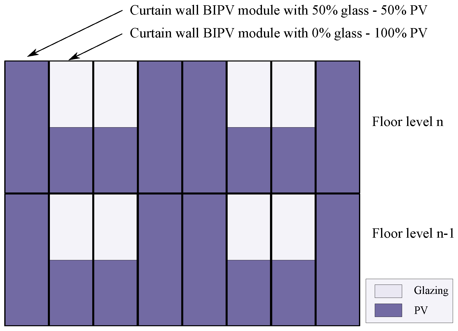
2.2. Energy Yield and Aesthetics

When designing the BIPV system, a trade-off needs to be made between the aesthetics and the energy-yield of the installation. A different approach exists between BAPV and BIPV. For BAPV, the electrical installation is typically done on an existing structure. A high energy yield is of primary importance as the motivation to place it can be found in reduced electricty costs. For BIPV, the energy yield is of secondary importance, whereas aesthetics and building regulation standards are primary factors to take into account [54]. Neglecting the importance of the energy yield could, however, lead to a less favourable position of BIPV compared to other measures that are used to reduce the energy consumption and ecological footprint of the building [55].
As compared to conventional PV systems, partial shading due to adjacent structures, building elements (e.g., pipes and ducts), frame edges, or the curvature of the installation is more prevalent in BIPV installations [36,47,48,49]. As a consequence, the power output of the shaded modules and, more importantly, the unshaded modules will be reduced, depending on the electrical configuration. The mismatch losses due to partial shading are specific for each installation, though studies indicate losses ranging from 5–25% [53,56,57,58].
This impact can, however, be limited by implementing the MPPT on smaller scales, e.g., per panel and not per string. To increase the power output, it is advisable to do the MPPT per module (distributed MPPT) and not per string. A micro-inverter (DC/AC) or power optimizer (DC/DC) solution is, thus, preferred to the traditional string inverter approach.

2.3. Flexibility

Flexibility relates to the architectural freedom during the design stage. In everyday structures, such as a casual office building, it can be advantageous to use arrays of standardized BIPV modules in order to reduce costs. This could, however, lead to a rather monotonous façade. When partial shading is not an issue, a string inverter could be used for the electrical installation, which is again beneficial from a cost point of view.
In more prestigious buildings, multiple types of PV (mono-, poly-, or thin film) can be present under a variety of forms. The electrical characteristics of these panels differ due to the different electrical properties of the used material, the size, and the orientation. Since aesthetics are of focal importance [54,55], this seems to be the preferred scenario, despite the higher impact on the electrical installation. Even when partial shading effects are negligible, the variety in output parameters favours the use of module-level converters as stringing becomes difficult or even impossible.

2.4. Modularity

This criterion relates to the ease of the practical construction of the installation. A modular system can easily be built and is the most plug-and-play option. This modularity aspect needs an evaluation for both the mechanical and electrical installation. The main focus of this paper, however, is on its electrical aspect. Modularity in its ultimate form would mean that the mechanical and electrical installation of the building can be carried out simultaneously by the same person. This person is preferably a construction worker with a minimal amount of extra training such that no skilled electrician is required to wire up the electrical installation after the façade itself has been placed. Relating to the previous aspects of flexibility, modularity does not mean that every BIPV module will be the same. The mechanical dimensions of a curtain wall BIPV module will be the same over a certain area of the building, e.g., one floor level, for the easiness of constructing the façade. Part of the BIPV module will be glass; the other part will be PV. The ratio glass/PV is, however, a parameter that can differ over different panels. This concept is illustrated in Figure 2 where BIPV modules are shown with 50% and 100% PV penetration. Furthermore, the glazing could also be changed to transparent PV modules which further increases the variety of electrical parameters in the system.
Cabling is another factor that strongly influences the modularity of the system. Ideally, a preinstalled AC or DC bus structure would run inside the BIPV modules. By doing so, the BIPV modules can be directly interconnected at the moment of their installation. At the corners of the building, the cables of the BIPV modules of the same floor level can then be connected to the main AC or DC backbone.

2.5. Engineering Effort

The engineering effort and associated costs for the electrical installation should be minimized, leading to a lower overall system cost and a low threshold for architects to employ BIPV in their designs.
In BAPV, the engineering effort is already very low due to the standardization in panel sizes (standard 60 or 72 cells), the smaller system size, and the fact that cabling can be easily routed behind the panels.
A high degree of standardization and modularity in BIPV systems will reduce the engineering effort required to design the electrical system. Reference [43] already indicated that preinstalled MLCs in the BIPV modules are a promising solution to decrease costs. By doing so, all modules can be placed in parallel to a common bus structure. The different rated powers become a nonissue when a MLC is used, and the cabling from one module to the next can be preinstalled.

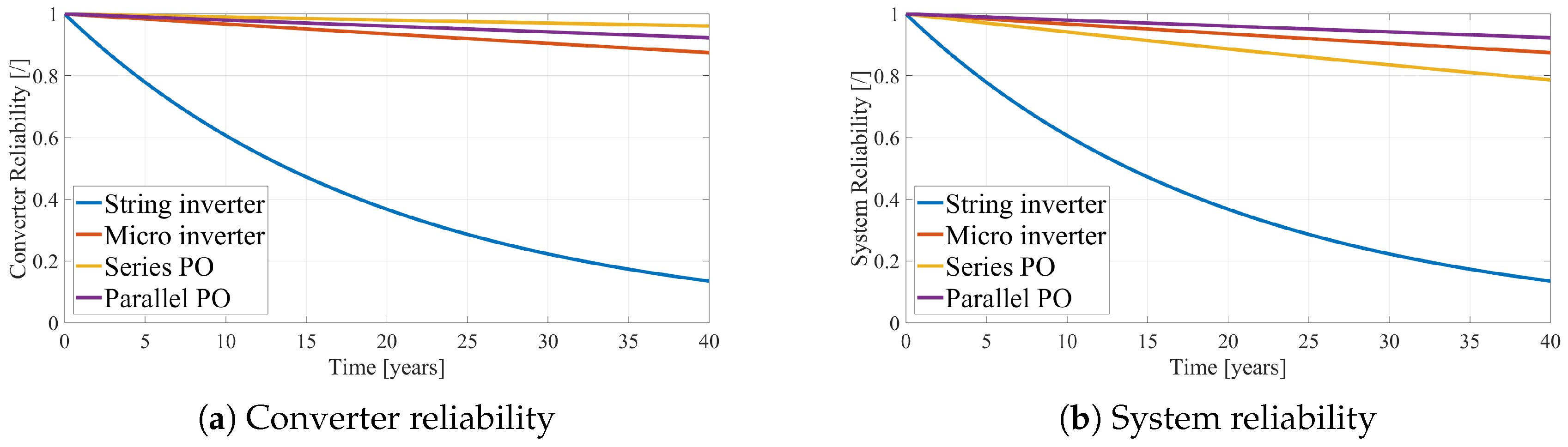
2.6. Reliability and Availability

As discussed in the previous points on the modularity and flexibility of the system, a fully integrated BIPV module with an integrated MLC is desired. The location of the MLC will be at the back of the PV panel or inside the metallic framework of the BIPV module. The major drawback of this choice is that the converter is difficult to reach after installation, making repairs or replacements undesirable or even impossible. The MLC lifetime should, thus, be comparable to the lifetime of the PV panel or even to the lifetime of the façade. The reliability of the converter becomes an important criterion to judge upon to enable this lifetime. A considerable amount of research is conducted to characterize the stresses of micro-inverters, considering mission profiles and degradation [59,60,61]. Commercial micro-inverter and power optimizers manufacturers use reliability as one of the key arguments to promote their products above competitors in the field and above the use of traditional string inverters. From Reference [62], the MTTF of string inverters is in the range of 20 years whereas micro-inverters report a MTTF of 300(+) years [63,64], certified by independent reliability test centers. Series power optimizers even report MTTF of 1000+ years, motivating that this is a consequence of the low amount of internal components, compared to string inverters [65].
No specific numbers have been found on parallel power optimizers. A higher reliability is, however, expected compared to micro-inverters as they only perform a DC/DC conversion, requiring less components and conversion steps. The converter reliability will, however, be lower compared to a series power optimizer, as a consequence of the higher voltage step-up, leading to more components and/or more complex circuit topologies [66,67]. For further calculations, the MTTF of parallel power optimizers is assumed to be 500 years.
From the above numbers, the converter reliability is plotted in Figure 3a for a time span of 40 years, corresponding to the desired lifetime of a BIPV façade. The string inverter performs the worst, leading to required replacements up to five times during the lifetime of a PV installation [59,68]. The replacements are not modeled in this study. The performance of micro-inverters and power optimizers is better, leading to an estimated reliability operational at 40 years of 87% for the micro-inverter, 96% for the series power optimizer (PO), and 92% for the parallel PO. These high numbers for distributed MPPT architectures have provoked skepticism within the PV industry and are criticized, as no or little field data is available to support these claims [62]. The numbers are mainly used to show specific trends, their numerical exactness is of secondary importance. Furthermore, the numbers that are reported in literature always referring to older converter designs that were installed several years ago. They can be used to derive a correct order of magnitude, but they do not take new designs with possible different failure mechanisms into account.
Even when special care is taken to have a reliable converter design, failures are inevitable. Hence, it is important that these failures only affect the converter and not the system as a whole. When a string inverter fails, the entire PV array becomes unavailable until the unit is repaired or replaced. As indicated in Reference [62], the independent and distributed architecture of MLC only affects one specific BIPV module. This leads to a reduced total power generation, but the system as a whole remains available. This is the case for micro-inverters and parallel power optimizers, if it is assumed that they are designed to fail safe. For series power optimizers, the malfunctioning of one device can lead to the malfunctioning of the entire string [69]. The string length of the leading commercial manufacturers is at least six and can go up to 25 (for a single phase grid connection). Taking these factors into account, the system reliability for the different cases is plotted in Figure 3b, showing that the parallel power optimizer approach leads to the highest system reliability. The reliability of the series power optimizer system has decreased due to the dependence on the correct functioning of the other optimizers within the string. Note that the MLC are assumed to be placed inside the metallic casing such that replacement is undesirable or even impossible. Specific failure modes of MLC and their consequences are investigated further on in this paper.
Furthermore, as reported by Reference [68], one of the main causes of PV inverter failure is related to inadequate protection from grid events, mainly surge voltages. To enhance the system’s reliability, this factor needs to be taken into account.

2.7. Monitoring and Communication

To analyze and assess the performance of the system, it is recommended to collect data regarding the generated PV power. When this data is analyzed over a certain period of time, it can help to schedule maintenance for the installation (cleaning, testing, and a comparative analysis). Furthermore, peer-to-peer communication can be beneficial to detect fault scenarios, as will be discussed in detail in Section 4.

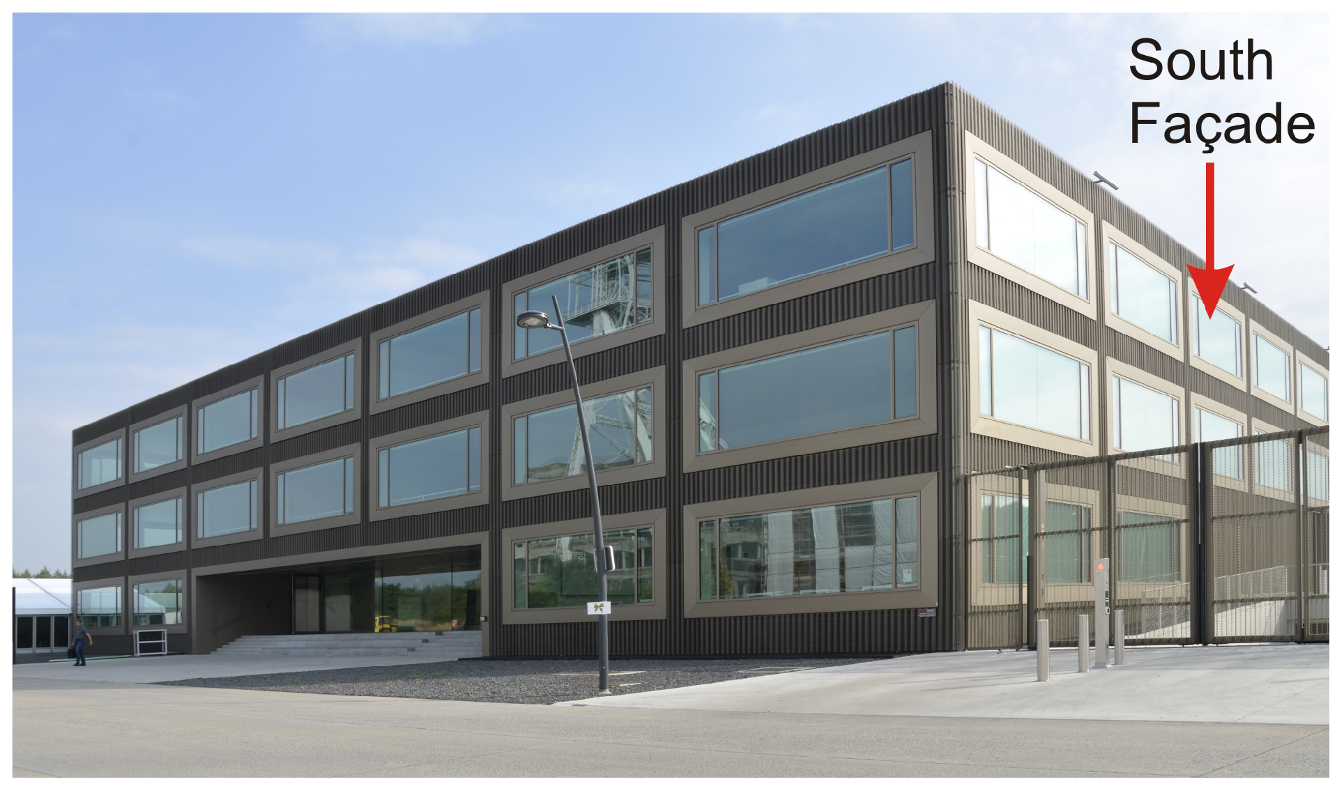
2.8. Technical Room Space and Cable Management—Case Study EnergyVille

The required technical room space (including technical shafts) for the BIPV installation needs to be minimal. This requirement is mainly valid for installations in densely populated areas where the price per square meter is elevated. Integrating the electronics and the cables is beneficial for this criterion. As already discussed under Section 2.4, using an AC or DC bus that runs along the modules can greatly simplify the cable management of the system.
To evaluate the technical room space, a case study has been carried out. Figure 4 shows the EnergyVille research institute building, located in Genk, Belgium. This building has a BAPV capacity of 369.15 kWp installed on the roof of the building, occupying a surface of 3326.17 m 2 . The PV strings are connected to the grid via 23 string inverters of 8.5 and 20 kVA, requiring an inverter room of, approximately, 100 m 3 .
The southern façade of this building has a strong potential for a façade BIPV installation due to its southern orientation and the absence of nearby obstacles. The available surface allows a peak power installation capacity of 97.8 kWp. Considering that each panel covers a surface of 1.63 m 2 and the available surface is around 531 m 2 (already disconsidering the occupied area by the windows) and taking into account that the partial shading deteriorates the energy generation by 10–13% [53], the estimated peak power of the southern façade is around 85 kWp. If a BIPV structure is installed and connected via local micro-converters, the installation leads to an increase of about 25% of the installed renewable generation while it does not require additional room space.

3. Evaluation of the Electrical Installations for BIPV

The objective of this section is to give an overview of the possible installation methods to electrically interconnect BIPV modules. A discussion on the advantages and disadvantages of each system will be provided. The following criteria are considered: monitoring, modularity, engineering effort, immunity against AC disturbances, immunity against partial shading, and reliability. The interconnection of BIPV modules to the AC grid or DC backbone, shown in Figure 1, leads to several options that will be explored. Figure 1a,b show the interconnection of BIPV modules directly to the AC grid, while Figure 1c,d represents the possible configurations to interconnect the BIPV modules to a DC microgrid.
Regarding the connection from the PV voltage level to the AC grid (single or three-phase) string inverters are often used [70,71,72]. The BIPV modules are connected in series, and the string is connected to one inverter. Micro-inverters, where each PV panel has its own low power inverter, are another possibility to connect the panels directly to the AC grid [73,74,75].
To guarantee immunity against AC disturbances, the BIPV modules can be connected via DC power optimizers to an LVDC grid (bipolar or unipolar), as shown in Figure 1. In this type of grid connection, two options are highlighted: a series operation of power optimizers and a parallel operation of power optimizers.
The systems abovementioned have strengths and weaknesses that will be presented considering the predefined criteria in this paper for a BIPV electrical installation. Table 1 presents this overview.

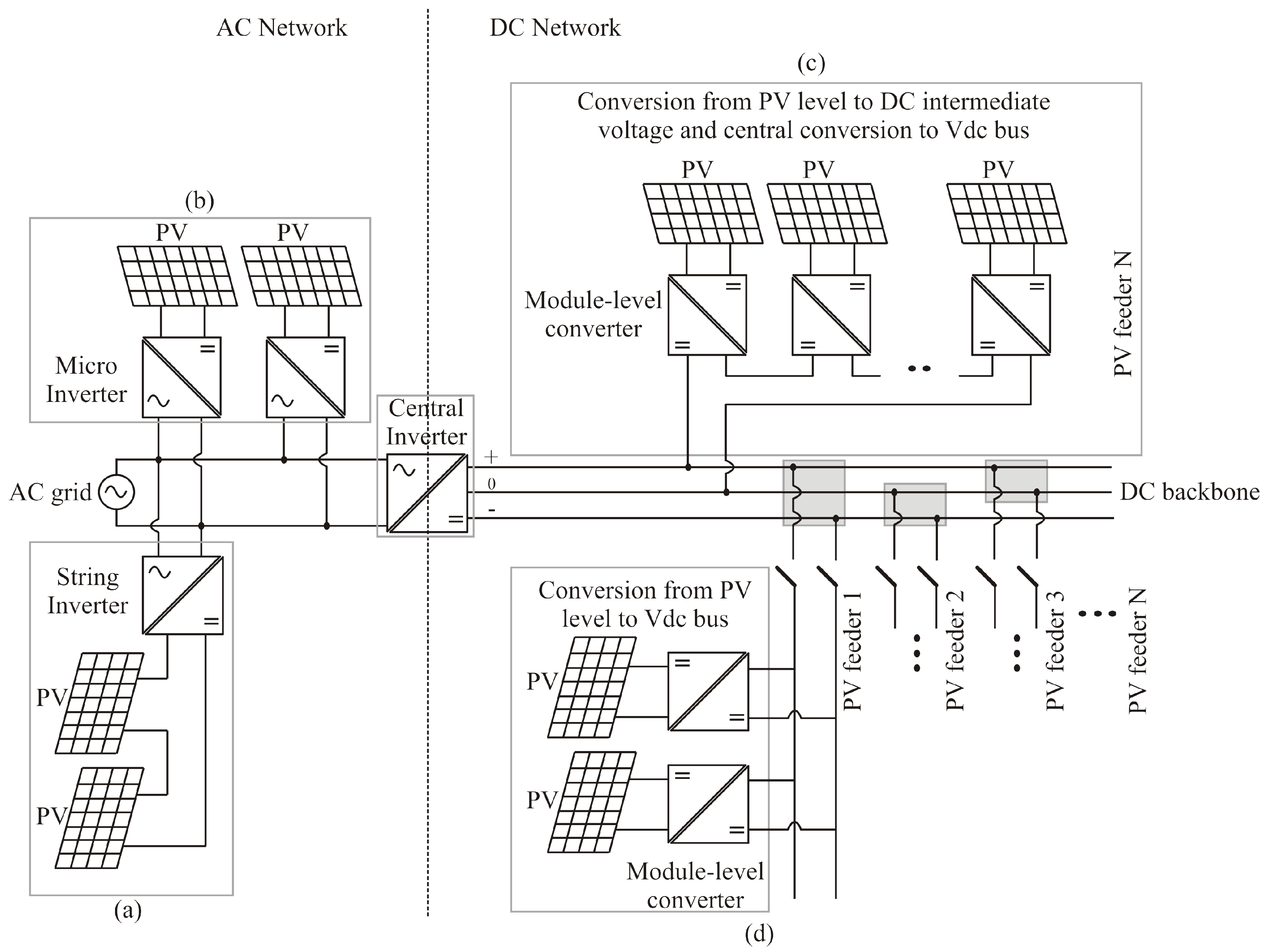
3.1. String Inverters

In the string inverter configuration, the DC input voltage of the inverter is the series connection of the BIPV modules. This solution can lead to a lower energy yield during partial shading conditions, thereby degrading the overall system performance. The use of string inverters for BIPV installations is widely reported in the literature [58,76,77,78,79,80,81,82,83,84,85,86].
The analysis of Table 1 shows that string inverters have an inferior performance for all criteria that were established for BIPV installations. The system is not modular since stringing needs to be done, requiring a high engineering effort to optimally design the number and length of the PV strings for a given installation. Especially when different sizes and types of PV are used, stringing becomes extremely challenging. System reliability is the lowest of all four options, but this number might be misleading since no repair was modelled. This was done because MLCs are placed in locations that are difficult or impossible to reach after installation. However, the string inverter is placed inside the protected volume and can, thus, be repaired when a fault occurs.

3.2. Micro-Inverters

For the case of micro-inverters, the system improves over several aspects. The problem of partial shading is now solved due to the distributed MPPT. Micro-inverters allow the fitting inside the frame of the BIPV module, thus becoming a real MLC. This combination is commonly referred to as an AC module. Micro-inverters are still coupled to the AC grid, making them vulnerable to AC grid disturbances. This is a major drawback given that the MLC is not difficult to reach after installation. An overvoltage on the AC grid could, thus, lead to a shutdown of the entire BIPV installation without the possibility to repair. From a reliability point of view, the major drawback of micro-inverters is probably the large electrolytic capacitors that are required to buffer the power output ripple at twice the switching frequency [44].
In literature, only one example is found that reports the use of micro-inverters. This is the case for the Copenhagen International School in Denmark [87].

3.3. Power Optimizers

Compared to inverters, power optimizers (POs) benefit from an immunity against AC grid disturbances. They are similar to micro-inverters regarding the distributed MPPT approach but they do a DC/DC and not an AC/DC conversion. Because of this, their internal power electronics circuit topology can be simpler. This is especially true for series power optimizers (SPOs) of which the outputs are connected in series to obtain a high voltage at the end of the string. Their output voltage is currently controlled via an extra current source converter, which can be placed inside the building. The largest benefit of this approach is that their circuit topology can be a standard buck-boost converter with a low amount of required components and low voltage stresses on the components due to their lower output voltage [88,89,90]. Both factors favour the converter reliability and compactness of SPOs. As indicated in Table 1, SPOs have the same score as string inverters from a modularity and engineering effort point of view. This is because the installation is not necessarily plug-and-play. For small installations this might be relatively straightforward, assuming that, for example, one string per floor level is required and all BIPV modules can be simply put in series. For larger buildings with longer strings, this is not necessarily the case as the amount of SPOs per string is limited by the technology and correct cabling becomes challenging again. Furthermore, one malfunctioning converter can lead to the improper operation of the entire string, as discussed in Section 2.6. In the literature, several detection strategies are proposed to detect and overcome this issue [91,92].
Parallel POs (PPOs) show the best overall performance for use in BIPV electrical installations. As with SPOs, PPOs employ a DC/DC conversion, but all the outputs are placed in parallel to a common DC bus as shown in Figure 1d. The DC bus is controlled by a central voltage source converter which could be the same inverter that controls the LVDC micro grid.
PPOs combine the advantages of a distributed MPPT, a lower amount of internal components compared to inverters, a high degree of flexibility and modularity, no impact of AC grid disturbances, and the highest overall system reliability due to the independence of other converters.
To the author’s best knowledge, no papers have been published where the SPO approach is used for BIPV applications. The use of PPOs for BIPV has first been reported by Reference [43], where a 200-V DC bus was used. The same approach was adopted by References [93,94,95], but a 380-V DC bus was employed. The reliability aspects concerning the embedment of this converter in the frame of a BIPV curtain wall element were treated in Reference [96].

3.4. LVDC Grid

A low-voltage DC architecture is adopted because of three main arguments. Primarily, an LVDC grid has a higher compatibility with the DC devices in the system. PV systems, energy storage systems, electric vehicles, LED lighting, IT equipment, and drives operate natively on DC or require DC along the power conversion chain [97,98,99,100,101]. Consequently, an LVDC grid can simplify the conversion steps, which is not only limited to DC-DC power optimizers. That results in an increased efficiency, a reduced component part count, and an enhanced component-level reliability. Secondly, an LVDC grid can transmit more power provided the same copper conductor cross section, thereby lowering costs [99,101]. Thirdly, because power converters are predominantly present in LVDC grids, power flows are actively controllable as compared to passive rectifiers used in AC systems.
Compared to the previous arguments that hold for LVDC grids in general, what are the specific advantages of an LVDC grid in a BIPV context? At first, the fewer conversion steps lead to a lower component count, which leads to an inherent higher reliability and an increased power density. This is beneficial for a frame-integration of the modules. Secondly, since both the input and output power are DC quantities, no energy buffering is required to filter out the power pulsation occurring at twice the grid frequency. The required buffer capacitance is given by Equation (1). To increase the power density and decrease costs, this is usually an electrolytic capacitor. The long-term reliability of this component is often questioned and is, therefore, a distinct advantage if electrolytic capacitors can be left out of the design [44,102].
C D C = P M P P 2 · ω g r i d · U D C · u r i p p l e
The voltage level can be seen as a degree of freedom which allows for a balance of the converter and cabling costs in the system. A higher voltage level leads to smaller cable cross sections and, thus, to cheaper cabling. However, a lower voltage level can reduce the required gain of the converter and allows the employment of components with a lower voltage rating, which might lead to cost reductions for the converter. To date, there are no internationally recognized standards or agreements on the exact voltage level of future LVDC grids. In telecom applications, a unipolar 48 V grid has been used for decades. In datacenters, a transition is going on from AC to bipolar DC with a voltage level of 380 V (+190 V/0/−190 V) [103]. Rodriguez et al. proposed the use of a bipolar 1500 V (+750 V/0/−750 V) grid for LVDC distribution that can be further divided in a bipolar 750 V (+375 V/0/−375 V) for high power loads and a unipolar 48 V bus for low power loads [104].

4. Converter Requirements

The discussion in Section 2.8 has led to the insight that a parallel power optimizer (PPO) approach is the most appropriate method to tackle the requirements that were set forward in Section 2. However, the previous analysis has shown that up to this date, the majority of BIPV installations still employ the more traditional string inverters to interconnect the BIPV modules. This section focuses on the specific requirements of a PPO for use in BIPV modules as an MLC. Every MLC is connected in parallel to the LVDC grid (the common DC bus) as shown in Figure 1d.

4.1. Compactness

The structural strength of BIPV modules is achieved via extruded aluminium profiles, and the MLC is preferably installed inside these cavities. In BAPV modules, the MLC is installed at the back of the PV panel, but in the case of BIPV, this space is occupied by thermal insulation material.
In general, a flat and long design is preferred to fit inside the framework. Currently commercially available MLC converters do not have this form factor, making it impossible to fit in this cavity. The implementation of wide-bandgap components such as Silicon Carbide (Sic) or Gallium Nitride (GaN) in the converter topology can help to achieve the required power density goals by an increased switching frequency, leading to smaller passive devices. The avoidance of transformers or inductors can lead to further size reductions, usually accomplished via switched capacitor circuits [105]. However, switched capacitor circuits can suffer from a lower reliability given that capacitors are one of the dominant components that lead to device failures [59]. Especially when MultiLayer Ceramic Capacitors (MLCCs) are used, a careful design is important due to their dominant short-circuit failure mode [102].

4.2. Wide Power and Input Voltage Range

In order to meet the scalability and flexibility requirements, it is preferable that the converter is compatible with a wide variety of PV panel types (mono-, polycristalline, and thin film) and sizes. The type of panel will already dictate part of its electrical characterisitics, but this is also influenced by the active surface, leading to a higher or lower amount of active cells. Apart from the standard 60 or 72 cell panel size, strongly deviating designs can occur, depending on the architect’s needs. Currently, commercial and research projects still focus on standard 60 or 72 cell PV modules, leading to designs that work for 20–50 V input voltage. This voltage range needs to be widened on both ends for future converter designs. The low input voltages might, however, lead to lower efficiencies due to the higher step-up [66,67]. Therefore, BIPV modules with a higher output voltage are more attractive from a power electronics point of view. This allows for simpler and smaller topologies to be used.
Furthermore, to optimize the energy-yield of the installation, the converters need to cover a wide input power range, preferably from 10–100% of the nominal peak power. The challenge is to maintain a decent efficiency over the entire operating range as typically the efficiency curve strongly decreases on the low-power operating range. Interleaved converters can help to achieve this goal by controlling the amount of phases based on the input power, thereby allowing a flatter efficiency curve [106].

4.3. Temperature Range and Cooling

Experimental results from previous studies indicate that the temperature in and around façade BIPV panels can strongly exceed 100 °C, depending on the installation and type of grid ventilation [53]. Measurements inside the framework where the converter will be placed indicate temperatures around 80 °C, leading to high thermal stresses for the converter components. As temperature and temperature cycling are one of the major stressors for power electronic components [59], cooling or heat-spreading will be required to keep the component temperature low enough to meet the reliability requirements. However, the physical dimensions of the heat sink need to be limited such that the size does not conflict with the compactness requirements. An alternative gaining importance in space-constrained applications is evaporative cooling using ultrathin heat pipes [107]. Active cooling using forced air flow is not preferred as the lifetime of fans is limited due to wear-out of the bearings [62], whereas active liquid cooling is considered to be expensive and difficult to implement in the system. BIPVT systems, where the generated heat of the PV panel is partly recovered in the building via forced convection, seems to gain lots of research interest [12]. No studies have been carried out that check whether this is also an effective approach to cool integrated electronics such as the MLC.

4.4. Lifetime

As already discussed in Section 2.6, the lifetime of the converter should be comparable to the lifetime of the PV panel, which is currently in the order of 25 years with a warranted power output of 80% or more. This is, however, still not equal to the current lifetime of a façade in the order of 30 to 50 years and which is also the design target for BIPV façades.
Micro-inverter and power optimizer producers provide warranties up to 25 years for their products [64,69]. These warranties are valid for converters that are attached to the back of a BAPV module and not in the framework of a BIPV module, which is a more challenging environment.
In Reference [108], an experimental study with accelerated lifetime tests was conducted to determine the reliability issues of module-level power electronics converters. Their conclusion states that a significant number of devices failed due to the applied stress and that this is most likely a consequence of design issues rather than manufacturing issues. Keeping this information in mind, combined with more severe temperature stresses that are expected in BIPV compared to BAPV, a design-for-reliability approach for BIPV MLCs is required.

4.5. Fail-Safe Functionalities

Fault-tolerant or fail-safe requirements relate to the correct functioning of the electrical system, after the occurrence of faults. When one MLC fails, it is important that this converter gets isolated from the system such that the BIPV feeder can remain operational with the remaining converters. This aids in achieving the availability target and is beneficial for the Return On Investment (ROI) of the installation [44]. Failures of PV arrays, their origin, consequences, and mitigation techniques are provided in Reference [109], but the failure of a single PV module connected via a power optimizer to an LVDC grid has not been covered. As the fault and leakage currents are much lower when the fault occurs on the PV side, this situation is different from a failure in a PV array. Novel fault detection methods as proposed in Reference [110] are recommended here.
In general, two types of faults can be distinguished: earth faults and short-circuit faults. This is shown in Figure 5. The influence on the availability of the system will be discussed for the case of earth faults, as they are related to the LVDC grid configuration and the presence of a high frequency transformer.

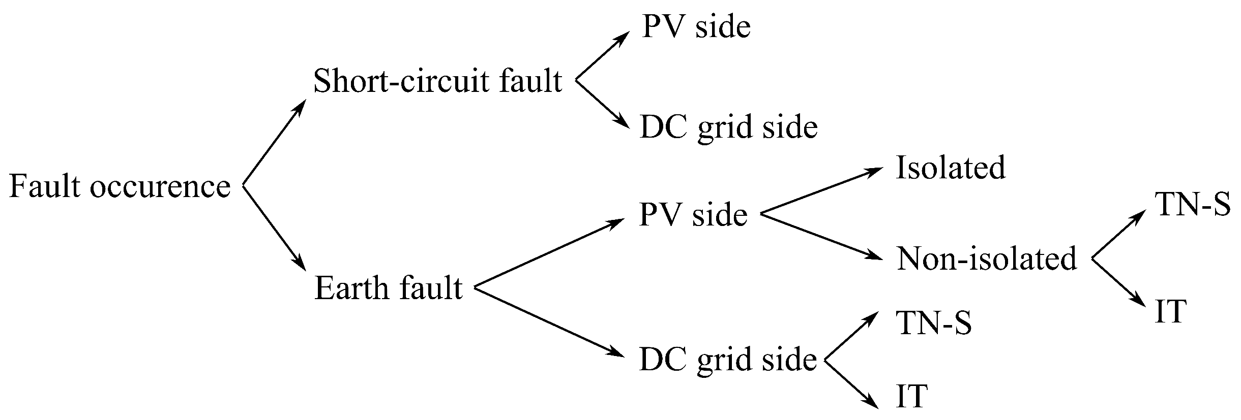
4.5.1. Earth Fault Selectivity

Assume an earth fault occurs at the output terminal of the MLC. The required response will depend on the LVDC grid configuration. In an IT grid, it is possible to organize the protection centrally, for example, as an extra feature of the central AC/DC converter. If all the protection equipment and logic is contained within this central box, communication is necessary between the central converter and the MLCs. When an earth fault is detected, the central converter can force a sequential shutdown of the MLCs in order to localize and isolate the faulty converter. This specific strategy is only possible in the case of an IT grid configuration, as it allows a certain time to react and search the earth fault. It comes, however, at the cost of a more complex protection scheme, based on communication between the MLCs and a central controller. The MLC needs to be equipped with a relay such that it can entirely disconnect from the LVDC grid when required. The central inverter needs to be equipped with an isolation monitoring device (IMD). Due to the extra costs and increased control complexity, this protection scheme is not recommended. The situation is, however, different for a TN-S grid configuration. When an earth fault occurs, the situation is similar to a short-circuit fault. The earth fault protection can, thus, be identical to the local short circuit protection measures. This can be, for example, a fuse. The fault current will be determined by the amount of PV generation of the other converters, the total capacitance of the LVDC grid, and the fault impedance.

4.5.2. Galvanic Isolation: Yes or No?

A transformer is often regarded as a component that reduces the overall efficiency and strongly increases the cost and volume of a DC/DC converter. It has, however, been successfully implemented in several designs [43,111,112] to realize the high step-up from the PV voltage level to the LVDC voltage level. In this work, an extra advantage of galvanic isolation will be analyzed.
As can be seen from the fault tree in Figure 5, the presence of a transformer affects only the situation where an earth fault occurs on the PV side. The three possible situations for this fault (assuming PV+ to PE) are analyzed in Table 2. A similar analysis is possible for a PV− to PE fault, but it is omitted here as the outcome is the same. This table provides evidence that a (high frequency) transformer in between the PV terminals and the LVDC grid improves the fault-tolerance and, thus, the reliability of the system by creating a very local IT grid. As in an IT system, a first fault has no direct consequence but merely places the potentials on the same level. If the converter has a local isolation monitoring device installed, it can sense this fault and shut down, but this is not a strict requirement. A second fault will instantly lead to a short-circuit at the PV terminals, which is measurable and requires a converter shut down and disconnection from the LVDC grid.

5. Conclusions

BIPV modules are installed during, not after, the construction phase and have a profound impact on the electrical installation and construction planning of a building. In this paper, system criteria were established for the electrical installations of building-integrated photovoltaics. These criteria serve as key performance indicators. Apart from energy-yield, factors such as engineering effort, availability, and modularity must also be considered when designing the installation as they impact project installation costs. Currently available electrical installation architectures, such as string inverters, micro-inverters, and series and parallel power optimizers, were compared according to the aforementioned criteria, favoring parallel module-level converters connected to a low-voltage DC grid for BIPV applications. LVDC grids allow a further reduction of the costs and an increase in the power density and lifetime compared to traditional AC grids. This is mainly because of the lower amount of conversion stages, leading to a lower amount of components. Although, the use of string inverters is mostly reported for BIPV. The requirements for BIPV module-level converters mainly differ from regular PV converters in terms of compactness, input range, and operating temperature range. Several methods were discussed that allow an improvement of these aspects for future BIPV converter designs. Furthermore, BIPV module-level converters must incorporate fault-tolerance techniques to meet the building element’s lifetime requirements. Due to the difficulties in replacing the converter when it is embedded inside the framework of the BIPV module, it is of utmost importance that the converter is designed to fail safe such that a converter failure does not result in a system failure. Fault conditions in BIPV module-level converters were considered for different grounding configurations. Compared to the current trend of going to non-isolated PV converters, we recommend the use of transformer-isolated topologies which increase the fault tolerance of the installation as a whole. The preferred grounding configuration is TN-S, as it allows for simple fault discrimination based on the current intensity.

Author Contributions

Conceptualization, S.R.; resources, J.D.; supervision, J.D.; validation, M.D.V. and G.V.d.B.; writing—original draft, S.R.; writing—review and editing, M.D.V., G.V.d.B., and J.D.

Funding

This project received the support of the European Union, the European Regional Development Fund ERDF, Flanders Innovation & Entrepreneurship, and the Province of Limburg. G. Van den Broeck, funded by a PhD grant of the Research Foundation Flanders (FWO).

Conflicts of Interest

The authors declare no conflict of interest.

Abbreviations

The following abbreviations are used in this manuscript:
ACAlternating Current
BAPVBuilding-Applied Photovoltaics
BIPVBuilding-Integrated Photovoltaics
BIPVTBuilding-Integrated Photovoltaics Thermal
DCDirect Current
EPBDEnergy Performance of Buildings Directive
GaNGallium Nitirde
IMDInsulation Monitoring Device
ITHigh-resistance grounded (from French: Isolé—Terre)
KPIKey Performance Indicator
LVDCLow-Voltage Direct Current
MIMicro-inverter
MLCModule Level Converter
MLCCMultilayer Ceramic Capacitor
MPPMaximum Power Point
MPPTMaximum Power Point Tracker
NZEBNear Zero Energy Buildings
PPOParallel Power Optimizer
PVPhotovoltaics
SETStrategic Energy Technology
SIString Inverter
SiCSilicon Carbide
SPOSeries Power Optimizer
TN-SLow-resistance grounded (from French: Terre-Neutre Séparé)

References

  1. Sinapis, K.; van den Donker, M. BIPV REPORT 2013—State of the Art in Building Integrated Photovoltaics; Technical Report; Solar Energy Application Centre: Eindhoven, The Netherlands, 2013. [Google Scholar]
  2. Prasad, D.; Snow, M. Designing with Solar Power: A Source Book for Building Integrated Photovoltaics (BiPV); Routledge: Abingdon-on-Thames, UK, 2014. [Google Scholar]
  3. Verberne, G.; Bonomo, P.; Frontini, F. BIPV Products for Facades and Roofs: A Market Analysis. In Proceedings of the European Photovoltaic Solar Energy Conference and Exhibition, Amsterdam, The Netherlands, 22–26 September 2014. [Google Scholar]
  4. Fath, K.; Stengel, J.; Sprenger, W.; Wilson, H.R.; Schultmann, F.; Kuhn, T.E. A method for predicting the economic potential of (building-integrated) photovoltaics in urban areas based on hourly Radiance simulations. Sol. Energy 2015, 116, 357–370. [Google Scholar] [CrossRef]
  5. Shah, A.V.; Schade, H.; Vanecek, M.; Meier, J.; Vallat-Sauvain, E.; Wyrsch, N.; Kroll, U.; Droz, C.; Bailat, J. Thin-film silicon solar cell technology. Prog. Photovolt. Res. Appl. 2004, 12, 113–142. [Google Scholar] [CrossRef]
  6. Hegedus, S. Thin film solar modules: The low cost, high throughput and versatile alternative to Si wafers. Prog. Photovolt. Res. Appl. 2006, 14, 393–411. [Google Scholar] [CrossRef]
  7. European Commision. Towards an Integrated Strategic Energy Technology (SET) Plan: Accelerating the European Energy System Transformation; European Commision: Brussels, Belgium, 2015. [Google Scholar]
  8. EU. Directive 2010/31/EU of the European Parliament and of the Council of 19 May 2010 on the energy performance of buildings (recast). Off. J. Eur. Union 2010, 3, 13–35. [Google Scholar] [CrossRef]
  9. Osseweijer, F.J.; van den Hurk, L.B.; Teunissen, E.J.; van Sark, W.G. A comparative review of building integrated photovoltaics ecosystems in selected European countries. Renew. Sustain. Energy Rev. 2018, 90, 1027–1040. [Google Scholar] [CrossRef]
  10. Defaix, P.R.; van Sark, W.G.; Worrell, E.; de Visser, E. Technical potential for photovoltaics on buildings in the EU-27. Sol. Energy 2012, 86, 2644–2653. [Google Scholar] [CrossRef]
  11. Kamel, R.; Ekrami, N.; Dash, P.; Fung, A.; Hailu, G. BIPV/T+ASHP: Technologies for NZEBs. Energy Procedia 2015, 78, 424–429. [Google Scholar] [CrossRef]
  12. Biyik, E.; Araz, M.; Hepbasli, A.; Shahrestani, M.; Yao, R.; Shao, L.; Essah, E.; Oliveira, A.C.; del Caño, T.; Rico, E.; et al. A key review of building integrated photovoltaic (BIPV) systems. Eng. Sci. Technol. Int. J. 2017, 20, 833–858. [Google Scholar] [CrossRef]
  13. Delisle, V.; Kummert, M. Cost-benefit analysis of integrating BIPV-T air systems into energy-efficient homes. Sol. Energy 2016, 136, 385–400. [Google Scholar] [CrossRef]
  14. Zhang, T.; Wang, M.; Yang, H. A Review of the Energy Performance and Life-Cycle Assessment of Building-Integrated Photovoltaic (BIPV) Systems. Energies 2018, 11, 3157. [Google Scholar] [CrossRef]
  15. Park, J.; Hengevoss, D.; Wittkopf, S. Industrial Data-Based Life Cycle Assessment of Architecturally Integrated Glass-Glass Photovoltaics. Buildings 2018, 9, 8. [Google Scholar] [CrossRef]
  16. Xu, X.; Feng, G.; Chi, D.; Liu, M.; Dou, B. Optimization of Performance Parameter Design and Energy Use Prediction for Nearly Zero Energy Buildings. Energies 2018, 11, 3252. [Google Scholar] [CrossRef]
  17. Ballarini, I.; De Luca, G.; Paragamyan, A.; Pellegrino, A.; Corrado, V. Transformation of an Office Building into a Nearly Zero Energy Building (nZEB): Implications for Thermal and Visual Comfort and Energy Performance. Energies 2019, 12, 895. [Google Scholar] [CrossRef]
  18. Martín-Chivelet, N.; Gutiérrez, J.C.; Alonso-Abella, M.; Chenlo, F.; Cuenca, J. Building retrofit with photovoltaics: Construction and performance of a BIPV ventilated façade. Energies 2018, 11, 1719. [Google Scholar] [CrossRef]
  19. Corrao, R. Mechanical tests on innovative BIPV façade components for energy, seismic, and aesthetic renovation of high-rise buildings. Sustainability 2018, 10, 4523. [Google Scholar] [CrossRef]
  20. Martinopoulos, G.; Serasidou, A.; Antoniadou, P.; Papadopoulos, A.M. Building integrated shading and building applied photovoltaic system assessment in the energy performance and thermal comfort of office buildings. Sustainability 2018, 10, 4670. [Google Scholar] [CrossRef]
  21. Goncalves, J.; Lehmann, J.; Yordanov, G.; Parys, W.; Baert, K.; Saelens, D. Experimental Performance of a Curtain Wall BIPV Element Under Realistic Boundary Conditions. In Proceedings of the European Photovoltaic Solar Energy Conference (EUPVSEC 2018), Brussels, Belgium, 24–28 September 2018. [Google Scholar]
  22. Goncalves, J.; Spiliotis, K.; Lehmann, J.; Baert, K.; Driesen, J.; Saelens, D. Experimental validation of a BIPV curtain wall model for building energy simulations. In Proceedings of the Advanced Building Skins Conference (ABS 2018), Bern, Switzerland, 1–2 October 2018. [Google Scholar]
  23. Lehmann, J.; Parys, W.; Goncalves, J.; Baert, K.; Saelens, D. Experimental analysis of the performance of a BIPV curtain wall component. In Proceedings of the Advanced Building Skins Conference (ABS 2017), Bern, Switzerland, 2–3 October 2017. [Google Scholar]
  24. Escarre, J.; Li, H.Y.; Sansonnens, L.; Galliano, F.; Cattaneo, G.; Heinstein, P.; Nicolay, S.; Bailat, J.; Eberhard, S.; Ballif, C.; et al. When PV modules are becoming real building elements: White solar module, a revolution for BIPV. In Proceedings of the 2015 IEEE 42nd Photovoltaic Specialist Conference, PVSC 2015, New Orleans, LA, USA, 14–19 June 2015; pp. 1–2. [Google Scholar] [CrossRef]
  25. Yu, H.; Wang, Q.; Lu, C.; Wei, C. The research on a new type of BIPV modules constructed by thin-film photovoltaic panel(or module)/PU/color organic-coated steel plate. In Proceedings of the 2014 IEEE 40th Photovoltaic Specialist Conference, PVSC 2014, Denver, CO, USA, 8–13 June 2014; pp. 2724–2727. [Google Scholar] [CrossRef]
  26. Martellotta, F.; Cannavale, A.; Ayr, U. Comparing energy performance of different semi-transparent, building-integrated photovoltaic cells applied to “reference” buildings. Energy Procedia 2017, 126, 219–226. [Google Scholar] [CrossRef]
  27. Virtuani, A.; Strepparava, D. Modelling the performance of amorphous and crystalline silicon in different typologies of building-integrated photovoltaic (BIPV) conditions. Sol. Energy 2017, 146, 113–118. [Google Scholar] [CrossRef]
  28. Bonomo, P.; Saretta, E.; Frontini, F. Towards the implementation of a BIM-based approach in BIPV sector. In Proceedings of the Advanced Building Skins Conference, Bern, Switzerland, 1–2 October 2018. [Google Scholar]
  29. Alamy, P.; Nguyen, V.K. PVSITES software tools for BIM-based design and simulation of BIPV systems. In Proceedings of the Advanced Building Skins Conference, Bern, Switzerland, 1–2 October 2018. [Google Scholar]
  30. Jakica, N. State-of-the-art review of solar design tools and methods for assessing daylighting and solar potential for building-integrated photovoltaics. Renew. Sustain. Energy Rev. 2018, 81, 1296–1328. [Google Scholar] [CrossRef]
  31. Fazelpour, F.; Ziasistani, N.; Nazari, P.; Nazari, P.; Ziasistani, N. Techno-Economic Assessment of BIPV Systems in Three Cities of Iran. Proceedings 2018, 2, 1474. [Google Scholar] [CrossRef]
  32. Zhang, Y.; Yan, Z.; Li, L.; Yao, J. A Hybrid Building Power Distribution System in Consideration of Supply and Demand-Side: A Short Overview and a Case Study. Energies 2018, 11, 3082. [Google Scholar] [CrossRef]
  33. Elinwa, U.K.; Radmehr, M.; Ogbeba, J.E. Alternative energy solutions using BIPV in apartment buildings of developing countries: A case study of North Cyprus. Sustainability 2017, 9, 1414. [Google Scholar] [CrossRef]
  34. An, H.J.; Yoon, J.H.; An, Y.S.; Heo, E. Heating and cooling performance of office buildings with a-Si BIPV windows considering operating conditions in temperate climates: The case of Korea. Sustainability 2018, 10, 4856. [Google Scholar] [CrossRef]
  35. Kuo, H.J.; Hsieh, S.H.; Guo, R.C.; Chan, C.C. A verification study for energy analysis of BIPV buildings with BIM. Energy Build. 2016, 130, 676–691. [Google Scholar] [CrossRef]
  36. Cerón, I.; Caamaño-Martín, E.; Neila, F.J. State-of-the-art of building integrated photovoltaic products. Renew. Energy 2013, 58, 127–133. [Google Scholar] [CrossRef]
  37. Montoro, D.F.; Vanbuggenhout, P.; Ciesielska, J. Building Integrated Photovoltaics: An Overview of the Existing Products and Their Fields of Application; Technical Report; Prepared in the Framework of the European Funded Project; SUNRISE: Saskatoon, SK, Canada, 2011. [Google Scholar]
  38. Zanetti, I.; Bonomo, P.; Frontini, F.; Saretta, E.; van den Donker, M.; Vossen, F.; Folkerts, W. Building Integrated Photovoltaics: Product Overview for Solar Building Skins- Status Report 2017; Technical, Report; Swiss BIPV Comptence Centre (SUPSI): Mano, Switzeland; Solar Energy Application Centre (SEAC): Eindhoven, The Netherlands, 2017. [Google Scholar]
  39. Vasiliev, M.; Nur-E-Alam, M.; Alameh, K. Recent Developments in Solar Energy-Harvesting Technologies for Building Integration and Distributed Energy Generation. Energies 2019, 12, 1080. [Google Scholar] [CrossRef]
  40. Pearce, J.; Meldrum, J.; Osborne, N. Design of Post-Consumer Modification of Standard Solar Modules to Form Large-Area Building-Integrated Photovoltaic Roof Slates. Designs 2017, 1, 9. [Google Scholar] [CrossRef]
  41. Attoye, D.E.; Aoul, K.A.T.; Hassan, A. A review on building integrated photovoltaic façade customization potentials. Sustainability 2017, 9, 2287. [Google Scholar] [CrossRef]
  42. Asfour, O.S. Solar and shading potential of different configurations of building integrated photovoltaics used as shading devices considering hot climatic conditions. Sustainability 2018, 10, 4373. [Google Scholar] [CrossRef]
  43. Liu, B.; Duan, S.; Cai, T. Photovoltaic DC-building-module-based BIPV system-concept and design considerations. IEEE Trans. Power Electron. 2011, 26, 1418–1429. [Google Scholar] [CrossRef]
  44. Formica, T.J.; Khan, H.A.; Pecht, M.G. The Effect of Inverter Failures on the Return on Investment of Solar Photovoltaic Systems. IEEE Access 2017, 5, 21336–21343. [Google Scholar] [CrossRef]
  45. Agamy, M.S.; Harfman-Todorovic, M.; Elasser, A.; Chi, S.; Steigerwald, R.L.; Sabate, J.A.; McCann, A.J.; Zhang, L.; Mueller, F.J. An Efficient Partial Power Processing DC/DC Converter for Distributed PV Architectures. IEEE Trans. Power Electron. 2014, 29, 674–686. [Google Scholar] [CrossRef]
  46. Dragicevic, T.; Lu, X.; Vasquez, J.C.; Guerrero, J.M. DC Microgrids—Part 1: A Review of Control Strategies and Stabilization Techniques. IEEE Trans. Power Electron. 2016, 31, 4876–4891. [Google Scholar] [CrossRef]
  47. Petter Jelle, B.; Breivik, C.; Drolsum Røkenes, H. Building integrated photovoltaic products: A state-of-the-art review and future research opportunities. Sol. Energy Mater. Sol. Cells 2012, 100, 69–96. [Google Scholar] [CrossRef]
  48. Heinstein, P.; Ballif, C.; Perret-Aebi, L.E. Building integrated photovoltaics (BIPV): Review, potentials, barriers and myths. Green 2013, 3, 125–156. [Google Scholar] [CrossRef]
  49. Ikkurti, H.P.; Saha, S. A comprehensive techno-economic review of microinverters for Building Integrated Photovoltaics (BIPV). Renew. Sustain. Energy Rev. 2015, 47, 997–1006. [Google Scholar] [CrossRef]
  50. Bidram, A.; Davoudi, A.; Balog, R.S. Control and circuit techniques to mitigate partial shading effects in photovoltaic arrays. IEEE J. Photovolt. 2012, 2, 532–546. [Google Scholar] [CrossRef]
  51. Freitas, S.; Brito, M. Maximizing the Solar Photovoltaic Yield in Different Building Facade Layouts. In Proceedings of the European Photovoltaic Solar Energy Conference and Exhibition, Hamburg, Germany, 14–18 September 2015; pp. 1–5. [Google Scholar] [CrossRef]
  52. Sinapis, K.; Litjens, G.; van den Donker, M.; Folkerts, W.; van Sark, W. Outdoor characterization and comparison of string and MLPE under clear and partially shaded conditions. Energy Sci. Eng. 2015, 3, 510–519. [Google Scholar] [CrossRef]
  53. Broeck, G.V.D.; Parys, W.; Goverde, H.; Putten, S.V.D.; Poortmans, J.; Driesen, J.; Baert, K. Experimental analysis of the performance of facade-integrated BIPV in different configurations. In Proceedings of the 32nd European Photovoltaic Solar Energy Conference and Exhibition, Munich, Germany, 20–24 June 2016; pp. 1–5. [Google Scholar]
  54. Marc, M. Towards a broad BIPV deployment: What is needed? In Proceedings of the EnergyVille BIPV Workshop, Genk, Belgium, 8 December 2015. [Google Scholar]
  55. Saelens, D. EnergyVille BIPV Roadmap. In Proceedings of the Belgian BIPV Workshop, Brussels, Belgium, 7 September 2017. [Google Scholar]
  56. Gross, M.A.; Martin, S.O.; Pearsall, N.M. Estimation of output enhancement of a partially shaded BIPV array by the use of AC modules. In Proceedings of the Conference Record of the Twenty Sixth IEEE Photovoltaic Specialists Conference, Anaheim, CA, USA, 29 September–3 October 1997; pp. 1381–1384. [Google Scholar] [CrossRef]
  57. Van der Borg, N.; Jansen, M. Energy loss due to shading in a BIPV application. In Proceedings of the 3rd World Conference on Photovoltaic Energy Conversion, Osaka, Japan, 11–18 May 2003; Volume 3, pp. 2220–2222. [Google Scholar]
  58. Zomer, C.; Nobre, A.; Cassatella, P.; Reindl, T.; Rüther, R. The balance between aesthetics and performance in building-integrated photovoltaics in the tropics. Prog. Photovolt. Res. Appl. 2014, 22, 744–756. [Google Scholar] [CrossRef]
  59. Wang, H.; Liserre, M.; Blaabjerg, F. Toward reliable power electronics: Challenges, design tools, and opportunities. IEEE Ind. Electron. Mag. 2013, 7, 17–26. [Google Scholar] [CrossRef]
  60. Shen, Y.; Wang, H.; Blaabjerg, F. Reliability Oriented Design of a Grid-Connected Photovoltaic Microinverter. In Proceedings of the 2017 IEEE 3rd International Future Energy Electronics Conference and ECCE Asia, Kaohsiung, Taiwan, 3–7 June 2017; pp. 81–86. [Google Scholar]
  61. Zare, M.H.; Mohamadian, M.; Wang, H.; Blaabjerg, F. Reliability assessment of single-phase gridconnected PV microinverters considering mission profile and uncertainties. In Proceedings of the 8th Power Electronics, Drive Systems and Technologies Conference, PEDSTC 2017, Mashhad, Iran, 14–16 February 2017; pp. 377–382. [Google Scholar] [CrossRef]
  62. Chung, H.S.H.; Wang, H.; Blaabjerg, F.; Pecht, M. Reliability of Power Electronic Converter Systems; Institution of Engineering and Technology: Stevenage, UK, 2016; p. 489. [Google Scholar] [CrossRef]
  63. ABB Group. Application Note on micro-inverter Reliability; Technical Report; ABB Group: Zürich, Switzerland, 2015. [Google Scholar]
  64. Enphase. Reliability of Enphase Micro-Inverters; Enphase White Paper; Enphase: Fremont, CA, USA, 2009; pp. 1–10. [Google Scholar]
  65. Routledge, J. Panel Level Power Electronics—From Vision to Commercial Reality; Technical Report; Tigo Energy: Los Gatos, CA, USA, 2015. [Google Scholar]
  66. Josias de Paula, W.; Oliveira Júnior, D.D.S.; Pereira, D.D.C.; Tofoli, F.L. Survey on non-isolated high-voltage step-up dc–dc topologies based on the boost converter. IET Power Electron. 2015, 8, 2044–2057. [Google Scholar] [CrossRef]
  67. Forouzesh, M.; Siwakoti, Y.P.; Gorji, S.A.; Blaabjerg, F.; Lehman, B. Step-Up DC-DC converters: A comprehensive review of voltage-boosting techniques, topologies, and applications. IEEE Trans. Power Electron. 2017, 32, 9143–9178. [Google Scholar] [CrossRef]
  68. Petrone, G.; Spagnuolo, G.; Teodorescu, R.; Veerachary, M.; Vitelli, M. Reliability Issues in Photovoltaic Power Processing Systems. IEEE Trans. Ind. Electron. 2008, 55, 2569–2580. [Google Scholar] [CrossRef]
  69. SolarEdge. Power Optimizers Installation Guide; Technical Report; SolarEdge: Herzliya, Israel, 2016. [Google Scholar]
  70. Boztepe, M.; Guinjoan, F.; Velasco-Quesada, G.; Silvestre, S.; Chouder, A.; Karatepe, E. Global MPPT Scheme for Photovoltaic String Inverters Based on Restricted Voltage Window Search Algorithm. IEEE Trans. Ind. Electron. 2014, 61, 3302–3312. [Google Scholar] [CrossRef]
  71. Sangwongwanich, A.; Yang, Y.; Blaabjerg, F.; Sera, D. Delta power control strategy for multi-string grid-connected PV inverters. In Proceedings of the 2016 IEEE Energy Conversion Congress and Exposition (ECCE), Milwaukee, WI, USA, 18–22 September 2016; pp. 1–7. [Google Scholar] [CrossRef]
  72. Zhao, X.; Zhang, L.; Born, R.; Lai, J.S. Solution of input double-line frequency ripple rejection for high-efficiency high-power density string inverter in photovoltaic application. In Proceedings of the 2016 IEEE Applied Power Electronics Conference and Exposition (APEC), Long Beach, CA, USA, 20–24 March 2016; pp. 1148–1154. [Google Scholar] [CrossRef]
  73. Mohammadi, S.; Zarchi, H.A. An interleaved high-power two-switch flyback inverter with a fast and robust maximum power point tracker. In Proceedings of the 2016 7th Power Electronics and Drive Systems Technologies Conference (PEDSTC), Tehran, Iran, 16–18 February 2016; pp. 320–325. [Google Scholar] [CrossRef]
  74. Melo, F.C.; Garcia, L.S.; Freitas, L.C.; Coelho, E.A.A.; Farias, V.J.; Freitas, L.C.G. Proposal of a Photovoltaic AC-Module with a Single-Stage Transformerless Grid-Connected Boost Microinverter (STBM). IEEE Trans. Ind. Electron. 2017, 65, 2289–2301. [Google Scholar] [CrossRef]
  75. Zengin, S.; Deveci, F.; Boztepe, M. Decoupling Capacitor Selection in DCM Flyback PV Microinverters Considering Harmonic Distortion. IEEE Trans. Power Electron. 2013, 28, 816–825. [Google Scholar] [CrossRef]
  76. Mun, H.; Ho, J.; Chul, S.; Shin, U.C. Operational power performance of south-facing vertical BIPV window system applied in office building. Sol. Energy 2017, 145, 66–77. [Google Scholar] [CrossRef]
  77. Aste, N.; Pero, C.D.; Leonforte, F. The first Italian BIPV project: Case study and long-term performance analysis. Sol. Energy 2016, 134, 340–352. [Google Scholar] [CrossRef]
  78. Pola, I.; Chianese, D.; Bernasconi, A. Flat roof integration of a-Si triple junction modules laminated together with flexible polyolefin membranes. Sol. Energy 2007, 81, 1144–1158. [Google Scholar] [CrossRef]
  79. Fanni, L.; Virtuani, A.; Chianese, D. A detailed analysis of gains and losses of a fully-integrated flat roof amorphous silicon photovoltaic plant. Sol. Energy 2011, 85, 2360–2373. [Google Scholar] [CrossRef]
  80. Eke, R.; Senturk, A. Monitoring the performance of single and triple junction amorphous silicon modules in two building integrated photovoltaic (BIPV) installations. Appl. Energy 2013, 109, 154–162. [Google Scholar] [CrossRef]
  81. Pillai, R.; Aaditya, G.; Mani, M.; Ramamurthy, P. Cell (module) temperature regulated performance of a building integrated photovoltaic system in tropical conditions. Renew. Energy 2014, 72, 140–148. [Google Scholar] [CrossRef]
  82. Essah, E.A.; Rodriguez, A.; Glover, N. Assessing the performance of a building integrated BP c-Si PV system. Renew. Energy 2015, 73, 36–45. [Google Scholar] [CrossRef]
  83. Brigitte, Y.; Sauzedde, F.; Boillot, B.; Boddaert, S. Development of a building integrated solar photovoltaic thermal hybrid drying system. Energy 2017, 128, 755–767. [Google Scholar] [CrossRef]
  84. Aristizábal, A.J.; Páez, C.A. Experimental investigation of the performance of 6 kW BIPV system applied in laboratory building. Energy Build. 2018, 152, 1–10. [Google Scholar] [CrossRef]
  85. Chen, H.J.; Shu, C.M.; Chiang, C.M.; Lee, S.K. Energy Procedia The Indoor Thermal Research of the HCRI-BIPV Smart Window. Energy Procedia 2011, 12, 593–600. [Google Scholar] [CrossRef]
  86. Wittkopf, S.; Valliappan, S.; Liu, L.; Seng, K.; Chye, S.; Cheng, J. Analytical performance monitoring of a 142.5 kWp grid-connected rooftop BIPV system in Singapore. Renew. Energy 2012, 47, 9–20. [Google Scholar] [CrossRef]
  87. Macé, P.; Larsson, D.; Benson, J. Transition towards Sound BIPV Business Models—Inventory on Existing Business Models, Opportunities and Issues for BIPV; Technical Report; International Energy Agency—Photovoltaic Power Systems Programme: Paris, France, 2018. [Google Scholar]
  88. Modules, P.; Walker, G.; Walker, G.R.; Sernia, P.C. Cascaded DC–DC Converter Connection of Photovoltaic Modules. IEEE Trans. Power Electron. 2004, 19, 1130–1139. [Google Scholar] [CrossRef]
  89. Alonso, R.; Román, E.; Elorduizapatarietxe, S.; Ibáñez, P.; Apinaniz, S. Experimental Results of Intelligent PV Module for Grid-Connected PV Systems. In Proceedings of the 21st European Photovoltaic Solar Energy Conference and Exhibition, Dresden, Germany, 4–8 September 2006; Volume 53, p. 2297. [Google Scholar]
  90. Walker, G.R.; Pierce, J.C. PhotoVoltaic DC-DC module integrated converter for novel cascaded and bypass grid connection topologies—Design and optimisation. In Proceedings of the PESC Record—IEEE Annual Power Electronics Specialists Conference, Jeju, Korea, 18–22 June 2006; pp. 1–7. [Google Scholar] [CrossRef]
  91. Dong, M.; Dong, H.; Wang, L.; Yang, J.; Li, L.; Wang, Y. A Simple Open-Circuit Detection Strategy for a Single-Phase Grid-Connected PV Inverter Fed from Power Optimizers. IEEE Trans. Power Electron. 2018, 33, 2798–2802. [Google Scholar] [CrossRef]
  92. Dong, H.; Yang, J.; Dong, M.; Su, M.; Cao, Y. Open-circuit fault detection for inverter fed by non-communication series-connected power optimizer. In Proceedings of the IECON 2017—43rd Annual Conference of the IEEE Industrial Electronics Society, Beijing, China, 29 October–1 November 2017; pp. 2606–2610. [Google Scholar] [CrossRef]
  93. Ravyts, S.; Vecchia, M.D.; Zwysen, J.; Van den Broeck, G.; Driesen, J. Study on a cascaded DC-DC converter for use in building-integrated photovoltaics. In Proceedings of the 2018 IEEE Texas Power and Energy Conference (TPEC), College Station, TX, USA, 8–9 February 2018; pp. 1–6. [Google Scholar] [CrossRef]
  94. Ravyts, S.; Vecchia, M.D.; Van den Broeck, G.; Driesen, J. Experimental Comparison of the Efficiency, Power Density and Thermal Performance of Two BIPV Converter Prototypes. In Proceedings of the 2018 IEEE 6th Workshop on Wide Bandgap Power Devices and Applications (WiPDA), Atlanta, GA, USA, 31 October–2 November 2018; pp. 7–13. [Google Scholar] [CrossRef]
  95. Ravyts, S.; Dalla Vecchia, M.; Zwysen, J.; van den Broeck, G.; Driesen, J. Comparison Between an Interleaved Boost Converter Using Si MOSFETs Versus GaN HEMTs. In Proceedings of the PCIM Europe 2018; International Exhibition and Conference for Power Electronics, Intelligent Motion, Renewable Energy and Energy Management, Nuremberg, Germany, 5–7 June 2018; pp. 1–8. [Google Scholar]
  96. Van De Sande, W.; Daenen, M.; Spiliotis, K.; Gonçalves, J.; Ravyts, S.; Saelens, D.; Driesen, J. Reliability Comparison of a DC-DC Converter Placed in Building-Integrated Photovoltaic Module Frames. In Proceedings of the 2018 7th International Conference on Renewable Energy Research and Applications (ICRERA), Paris, France, 14–17 October 2018; pp. 412–417. [Google Scholar] [CrossRef]
  97. Engelen, K.; Shun, E.L.; Vermeyen, P.; Pardon, I.; D’hulst, R.; Driesen, J.; Belmans, R. The Feasibility of Small-Scale Residential DC Distribution Systems. In Proceedings of the 32nd Annual Conference on IEEE Industrial Electronics (IECON), Paris, France, 6–10 November 2006; pp. 2618–2623. [Google Scholar] [CrossRef]
  98. Baran, M.E.; Mahajan, N.R. DC distribution for industrial systems: Opportunities and challenges. IEEE Trans. Ind. Appl. 2003, 39, 1596–1601. [Google Scholar] [CrossRef]
  99. Agustoni, A.; Borioli, E.; Brenna, M.; Simioli, G.; Tironi, E.; Ubezio, G. LV DC distribution network with distributed energy resources: Analysis of possible structures. In Proceedings of the 18th International Conference and Exhibition on Electricity Distribution (CIRED), Turin, Italy, 6–9 June 2005; [Google Scholar] [CrossRef]
  100. Justo, J.J.; Mwasilu, F.; Lee, J.; Jung, J.W. AC-microgrids versus DC-microgrids with distributed energy resources: A review. Renew. Sustain. Energy Rev. 2013, 24, 387–405. [Google Scholar] [CrossRef]
  101. Elektrotechnik, D.K. Deutsche Normungs-Roadmap Gleichstrom im Niederspannungsbereich Version 1; Technical Report; Verband Der Elektrotechnik: Frankfurt, Germany, 2016; 138p. [Google Scholar]
  102. Wang, H.; Blaabjerg, F. Reliability of capacitors for DC-link applications in power electronic converters—An overview. IEEE Trans. Ind. Appl. 2014, 50, 3569–3578. [Google Scholar] [CrossRef]
  103. AlLee, G.; Tschudi, W. Edison Redux: 380 Vdc Brings Reliability and Efficiency to Sustainable Data Centers. IEEE Power Energy Mag. 2012, 10, 50–59. [Google Scholar] [CrossRef]
  104. Rodriguez-Diaz, E.; Chen, F.; Vasquez, J.C.; Guerrero, J.M.; Burgos, R.; Boroyevich, D. Voltage-Level Selection of Future Two-Level LVdc Distribution Grids: A Compromise between Grid Compatibiliy, Safety, and Efficiency. IEEE Electrif. Mag. 2016, 4, 20–28. [Google Scholar] [CrossRef]
  105. Chatterjee, U.; Gelagaev, R.; Masolin, A.; Driesen, J. Design of an intra-module DC-DC converter for PV application: Design considerations and prototype. In Proceedings of the IECON 2014—40th Annual Conference of the IEEE Industrial Electronics Society, Dallas, TX, USA, 29 October–1 November 2014; pp. 2017–2022. [Google Scholar] [CrossRef]
  106. Michal, V. Optimal peak-efficiency control of the CMOS interleaved multi-phase step-down DC-DC Converter with segmented power stage. IET Power Electron. 2016, 9, 2223–2228. [Google Scholar] [CrossRef]
  107. Mochizuki, M. Latest development and application of heat pipes for electronics and automotive. In Proceedings of the 2017 IEEE CPMT Symposium Japan (ICSJ), Kyoto, Japan, 20–22 November 2017; pp. 87–90. [Google Scholar] [CrossRef]
  108. Flicker, J.; Tamizhmani, G.; Moorthy, M.K.; Thiagarajan, R.; Ayyanar, R. Accelerated testing of module-level power electronics for long-term reliability. IEEE J. Photovolt. 2017, 7, 259–267. [Google Scholar] [CrossRef]
  109. Alam, M.K.; Khan, F.; Johnson, J.; Flicker, J. A Comprehensive Review of Catastrophic Faults in PV Arrays: Types, Detection, and Mitigation Techniques. IEEE J. Photovolt. 2015, 5, 982–997. [Google Scholar] [CrossRef]
  110. Rezgui, W.; Mouss, H.; Mouss, N.; Mouss, D.; Benbouzid, M.; Amirat, Y. Photovoltaic module simultaneous open-and short-circuit faults modeling and detection using the I-V characteristic. In Proceedings of the IEEE International Symposium on Industrial Electronics, Buzios, Brazil, 3–5 June 2015; pp. 855–860. [Google Scholar] [CrossRef]
  111. Kasper, M.; Ritz, M.; Bortis, D.; Kolar, J.W. PV Panel-Integrated High Step-up High Efficiency Isolated GaN DC-DC Boost Converter. In Proceedings of the Telecommunications Energy Conference ‘Smart Power and Efficiency’ (INTELEC), Hamburg, Germany, 13–17 October 2013; pp. 602–608. [Google Scholar]
  112. Mamarelis, E.; Petrone, G.; Sahan, B.; Lempidis, G.; Spagnuolo, G.; Zacharias, P. What is the best dc/dc converter for an AC module? Experimental analysis of two interesting solutions. In Proceedings of the ISIE 2011: 2011 IEEE International Symposium on Industrial Electronics, Gdansk, Poland, 27–30 June 2011; pp. 1759–1764. [Google Scholar] [CrossRef]
Figure 1. The possible electrical architectures for PV module interconnection to an AC or DC grid: (a) string inverters; (b) micro-inverters; (c) series power optimizer; and (d) parallel power optimizer.
Energies 12 01532 g001
Figure 2. The zoom on a small part of a typical apartment or office building façade where building-integrated photovoltaic (BIPV) curtain wall modules can be used. To illustrate the modularity principle, the size of the curtain wall element remains the same but the ratio glass/photovoltaics (PV) can be changed.
Energies 12 01532 g002
Figure 3. The predicted reliability of the different electrical architectures based on manufacturer reliability data. Note that repair is not modeled since the integrated converter is not servicable when installed in the module frame. The string inverter shows the lowest reliability but is installed on a servicable location which allows repair.
Energies 12 01532 g003
Figure 4. The EnergyVille building located in Genk, Belgium with 369.15 kW of peak PV installed on the roof.
Energies 12 01532 g004
Figure 5. An overview of the possible faults in a fault tree structure. A distinction is made between short-circuit and earth faults and the input (PV) versus the output (DC grid) side of the converter.
Energies 12 01532 g005
Table 1. The qualitative and quantitative analysis of possible BIPV electrical installation architectures. The grey boxes indicate the preferred option.
Criteria
System NetworkMonitoringModularityEngineering EffortImmunity against AC DisturbancesFlexibilityImmunity against Partial ShadingPredicted System Reliability after 40 Years
SInolowhighnolowno13.5%
MIyeshighlownohighyes87.5%
SPOyeslowhighyeshighyes78.9%
PPOyeshighlowyeshighyes92.3%
SI: String Inverter; MI: micro-inverter; SPO: Series Power Optimizer; PPO: Parallel Power Optimizer.
Table 2. An overview on the converter PV side earth faults for different grid configurations and distinguishing galvanic isolations.
Fault SchematicGrid TypeIsolatedConsequenceRequired ResponseDetection and Protection Device
Energies 12 01532 i001NAYesNo direct consequenceThe converter can remain operational. A second fault on the PV side will result in a short-circuit between PV+ and PV−./
Energies 12 01532 i002TN-SNoShort-circuit current between PV+ and PV− determined by PV panel I-V characteristicShut down and disconnect converter from input and outputLocal fault or insulation monitoring device
Energies 12 01532 i003ITNoShort-circuit dependent on the grouinding impedanc  Z G Shut down and disconnect converter from input and outputLocal fault or insulation monitoring device

