DC Grid for Domestic Electrification
by
 , , and
G. Arunkumar
1, 
D. Elangovan
1,*,
P. Sanjeevikumar
2 ,
,
Jens Bo Holm Nielsen
2,
Zbigniew Leonowicz
3 and
and
Peter K. Joseph
1 1
School of Electrical Engineering, Vellore Institute of Technology (VIT) University, Vellore, Tamilnadu 632014, India
2
Center for Bioenergy and Green Engineering, Department of Energy Technology, Aalborg University, 6700 Esbjerg, Denmark
3
Department of Electrical Engineering, Wroclaw University of Technology, Wyb. Wyspianskiego 27, I-7, 50370 Wroclaw, Poland
*
Author to whom correspondence should be addressed.
Energies 2019, 12(11), 2157; https://doi.org/10.3390/en12112157
Submission received: 26 April 2019
/
Revised: 22 May 2019
/
Accepted: 27 May 2019
/
Published: 5 June 2019
(This article belongs to the Special Issue Power Electronic Converter Configuration and Control for DC Microgrid Systems)
Abstract
:Various statistics indicate that many of the parts of India, especially rural and island areas have either partial or no access to electricity. The main reason for this scenario is the immense expanse of which the power producing stations and the distribution hubs are located from these rural and distant areas. This emphasizes the significance of subsidiarity of power generation by means of renewable energy resources. Although in current energy production scenario electricity supply is principally by AC current, a large variety of the everyday utility devices like cell phone chargers, computers, laptop chargers etc. all work internally with DC power. The count of intermediate energy transfer steps are significantly abridged by providing DC power to mentioned devices. The paper also states other works that prove the increase in overall system efficiency and thereby cost reduction. With an abundance of solar power at disposal and major modification in the area of power electronic conversion devices, this article suggests a DC grid that can be used for a household in a distant or rural area to power the aforementioned, utilizing Solar PV. A system was designed for a household which is not connected to the main grid and was successfully simulated for several loads totaling to 250 W with the help of an isolated flyback converter at the front end and suitable power electronic conversion devices at each load points. Maximum abstraction of operational energy from renewable sources at a residential and commercial level is intended with the suggested direct current systems.
1. Introduction
The World Energy Outlook 2015 statuses that nearly 17% of the total inhabitants in the world lacks access to electric power at homes [1]. As per the reports of International Energy Agency, India has over 237 million citizens belonging to this category. According to CEEW (Council for Energy, Environment, and Water), over 50% of houses in the states of West Bengal, Bihar, Madhya Pradesh, Uttar Pradesh, Jharkhand, Orissa has a shortage of electric power in spite of being grid connected. Regardless of the efforts put in over the years to electrify rural stretches, many households in five out of these six states have not more than 8 h of supply or no supply at all and are regularly subjected to blackouts. The states may perhaps slightly better conditions but the same cannot be said for the unfortunate low-income strata of citizens lacking admission to electricity. Most of these homes use kerosene for their lighting purposes which give poor illumination. It also sends out unhealthy fumes, may cause fire perils, ecologically unfavorable and also too exclusive when bought at market tariffs unless subsidized by the Government [2,3].
It may come as surprise to see that not all houses in a village in India maybe be electrified even though the village is said to be grid connected. By the explanation provided by the Government of India, “A village is considered electrified when 10% of the homes in a village are connected to the grid.” As on May 2016, 18,452 villages are remaining to be electrified [4]. Nevertheless, during recent past numerous of individuals were able to harvest electricity with the help of fleet-footed economic growth and along with numerous sponsored programs, the country has made significant augmentation in its electrical infrastructure. In the energy production sector, the fossil fuels and conventional methods of power generation are losing it demand rapidly since policymakers around the globe are stressing on the effects of global warming and climate changes. The world is advancing towards green energy to meet the ever increasing power demand, thus requiring a mixing up numerous resources both conventional and non-conventional [5]. The unique energy situation in India is making the country’s growth objectives to be revised and modified so that it strive to meet its current demands as well as generating energy which is clean, efficient and environmental friendly [6]. This encourages economy to take up more enterprises and initiatives to extract maximum energy from renewable resources.
The abundance of solar radiation and decreasing prices of Photovoltaic components ease of its maintenance and scalability is making Solar PV generation more popular among renewable energy sources [7]. Even though in most parts of the country the sun shines adequately up to 10 to 12 h a day for the most part of a year, the huge impact of distributed solar power has not been amply exploited. In places receiving sunlight higher than 1400 equivalent peak hours annually, the gap in power shortage can be bridged by using solar energy. The government of India has become conscious of these facts and is enhancing the consumption of renewable power sources, specifically the solar power, in meeting the demand-supply gap nationwide. Thus, pertinent strategic guidelines have been created for endorsing solar power usage across the country. It aims at achieving 100 GW PV (photovoltaic) capacity from current statistics of 20 GW by 2022 with the assistance of the Jawaharlal Nehru National Solar Mission (JNNSM). The JNNSM intends to power rural areas, which was deprived of electricity before. Encouraged by the progress made in 4 years it now aims to achieve 100 GW by 2022 with solar rooftops contributing 40 GW of this. In the light of the launch of JNNSM program few states launched their separate solar policies. The Solar Energy policy of Tamil Nadu initiated in 2012 is targeting 5 GW solar energy by 2023. To encourage solar rooftops the Tamilnadu government provides huge incentives and almost 30% subsidies to buildings incorporating solar rooftops. This movement has encouraged the studies and improvement on Low Voltage DC arrangements, as they are suitable for residence applications as well as can be easily integrated with renewable energy sources and storage systems [8,9]. The rising demand for aggregating renewable energy resources is bringing back DC into the energy distribution frame since it is easy to integrate renewable sources into the grid in such case. Most loads at the utilization terminal these days are DC or non-sinusoidal. As a result, many types of exploration have been going on dc dissemination systems and their prospective uses in residential applications [10]. The DC also enjoys numerous other advantages over the AC system, one of the significant being the reduced number of converters at each power conversion legs and better efficiency in comparison with AC grid. If the solar DC output voltage is fed straight to these device appliances, the conversation stages are reduced from three stage DC-AC-DC to two stage DC-DC when solar PVs and fuel cells are interconnected with DC microgrids [11,12,13,14,15]. Additionally, the lack of reactive power decreases the current required to pass the equal magnitude of energy [16] and also mitigates the issues of skin effect, power factor and harmonics [17].Studies conducted on DC distribution systems in various residences located in various locations and different topologies in the United States showed that energy savings estimation can be up to 5% in case of a non-storage system and up to 14% for a system using storage [18,19]. There are more optimistic researchers that aim to pull of energy savings of 25–30% [20]. Exchanging the prevailing alternating current delivery grids with direct current is impracticable and economically non-viable. This is why DC can become the idyllic pick when it comes to energizing remote areas which are not connected to the main power grid, also known as “island areas”. This type of areas can be made self-sustainable by harnessing non-conventional energy resources.
This article proposes one direct current microgrid which uses Solar PV to facilitate a domestically situated appliance in an isolated area to energize itself. Microgrids are entities that can be self-controlled and operated in island or grid connected mode when interconnected with the local distribution systems [21]. They mainly refer to small-scale power network having voltage levels lesser than 20 kV and power rating up to 1 MW. Using this system, unsolicited energy changeover steps and losses accompanying by the same are eliminated. The major advantage of DC Microgrid is its ability to comply easily with DC loads and Distributed Energy Resources (DERs). For example, only a DC-DC conversion stage is required in a DC Microgrid when it is connected to solar PV and a battery storage, thus provides a simple and cost cutting structure with the better control strategy. This boosts the general system efficiency and makes the system less complicated. It also supplements the performance and the life of components [22,23]. The absence of normalization, instruction and improvement of protection devices for DC-DC converters are few of the major problems that DC power systems must solve, before being regarded as an appropriate option that supersedes AC power systems in rural and island areas [17].
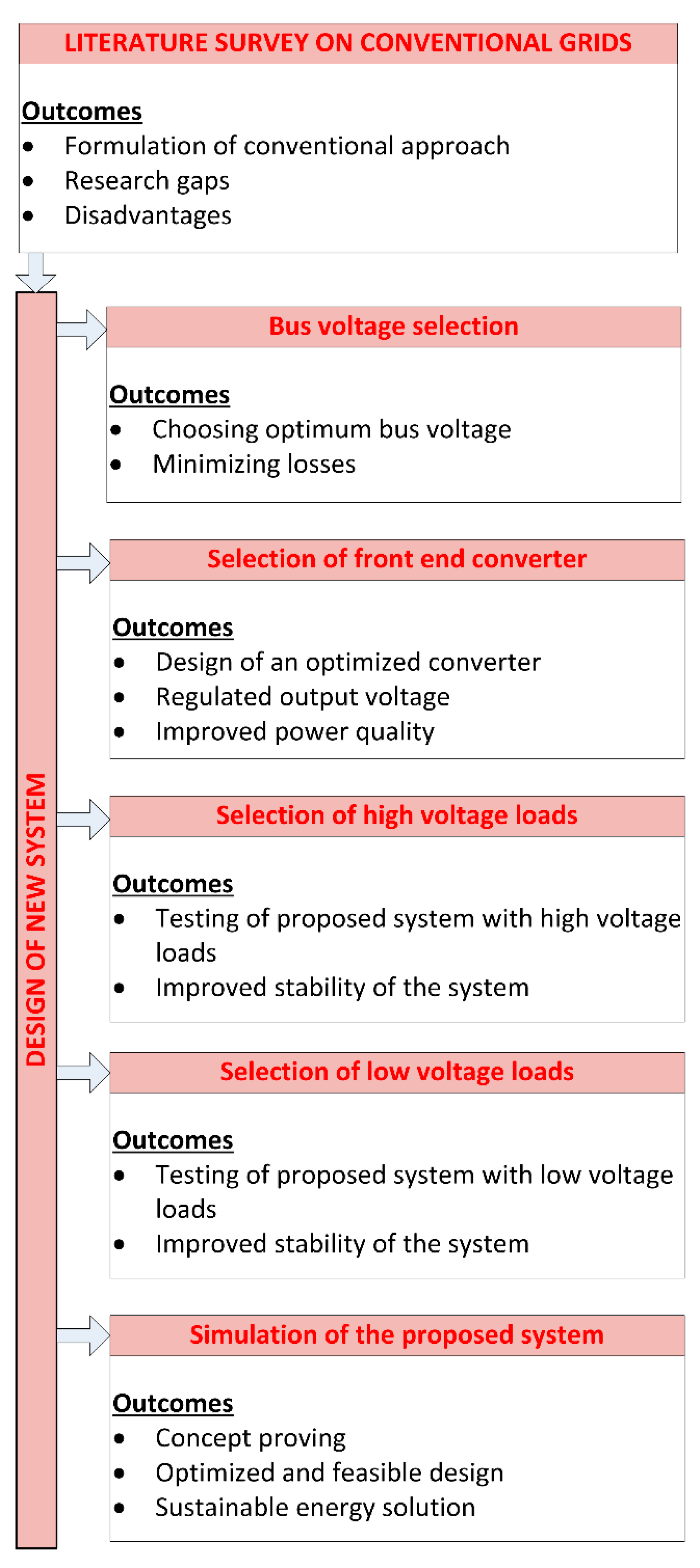
Figure 1 illustrates the methodology outline of this research works. The works done and the outcome of this methodology is explained in coming sessions.
Existing Works in DC Microgrids
An analysis has been performed on a 48 V DC microgrid integrated with PV panels using very effective DC loads utilized in a multi-storied building in India [24,25]. The findings show that the DC microgrid is far efficient in bringing cost savings, thereby dropping the electricity invoices. A practical employment of low power solar system designed to supply the basic power needs of a low-income family in India has been studied [9]. The system supplies a cumulative load of 125 W from PV Panel. This system may not be able to meet up to the power requirement of a fully electrified and digital household but is able to show that when minimizing the system cost is priority a low voltage DC distribution system have no challengers.
Works on larger test beds such as 5 kW with high DC link voltage of 380 V has also been conducted to study the feasibility of DC as distribution system [15]. A solar hybrid system of grid connection along with solar array panel feeding 220 V DC link powering up an entire household is realized in [5]. An effective Maximum Power Point Tracking (MPPT) algorithm to obtain constant DC voltage of 12 V or 24 V using a PI controller is studied in [6]. An Off Grid Home (OGH) which is inverter less system to power lighting loads are deployed in [8].
Green Office and Apartments (GOA) technology is a solution offered to ensure all day power using an integration of grid and batteries charged from solar PV [26]. A DC microgrid consisting of 250 W solar panel and charge controllers to regulate battery charging has been proposed in [27,28]. Suggest a novel reconfigurable inverter topology which can perform DC to DC, DC to AC and grid connection at the same time. An experimental prototype of a power balancing circuit to solve mismatching problems while connecting various renewable to a DC link is proposed in [29,30]. Elaborates the concepts of DC house and Null Net Energy (NNE) buildings which supply DC to residential buildings. Various Multiple Input Multiple Output (MIMOCs) DC-to-DC converters that can be used as front end converter for a DC distribution in future homes is discussed in [31,32,33,34,35,36,37,38,39,40,41,42].
Apart from the conventional microgrid works, some researches are done in the field of advanced aspects of microgrid implementation. Researches [43,44,45] discusses about the consumers with distributed storage capacity. In this case, the demand sharing and power quality improvement will be much easier. Refs. [46,47] considers renewable energy sharing mechanism of multiple consumers, rather than the individual renewable energy harvesting topology. Since this research work discusses about the implementation of a DC microgrid in rural domestic area, this advanced techniques are neglected for the initial phase. In addition, since solar energy is weather dependent, to ensure a regulated supply irrespective of the weather or time, storage devices or weather independent renewable energy sources like fuel cells need to be integrated to the microgrid [48,49]. This part also neglected from the simulation, as the outcome will be the same.
2. Selection of Bus Voltage
The DC grid distribution system having several practical challenges in distributing a regulated power supply [32]. The DC microgrid supplying low voltage and higher currents requires high gauge cables, which leads to an increase in overall losses [32,33]. Thus in order to reduce the losses and save the installation cost, the DC microgrid voltage must be sufficiently high enough. As a paradox, if the link voltage is too high, it leads to the occurrence of sparks, arcing and electric shock. Many research works have been done in order to reduce the arcing and spark phenomenon in order to optimize the DC distribution system. However, this paper deals with loads not requiring more than 240 V voltage and 3.42 A current. Hence the DC link voltage is taken as 72 V [34,35,36,37].
Since the majority of the domestic electrical appliances internally needs DC voltage for its operation, which is obtained conventionally by stepping down of rectified AC voltage supply [38]. Renewable energy resources can directly produce this low value of DC voltage [39]. Hence the rectification stage can be avoided if the load is powered with DC. A customary magnitude for DC grid voltage is not fixed for a microgrid. The chosen loads for this research has rated voltage varies in the range from 5 V to 230 V. For ensuring a coherent transition from grid voltage to rated load voltage, an optimum value of grid voltage of 72 V is chosen [40,41].
3. Front End Isolated DC to DC Converter
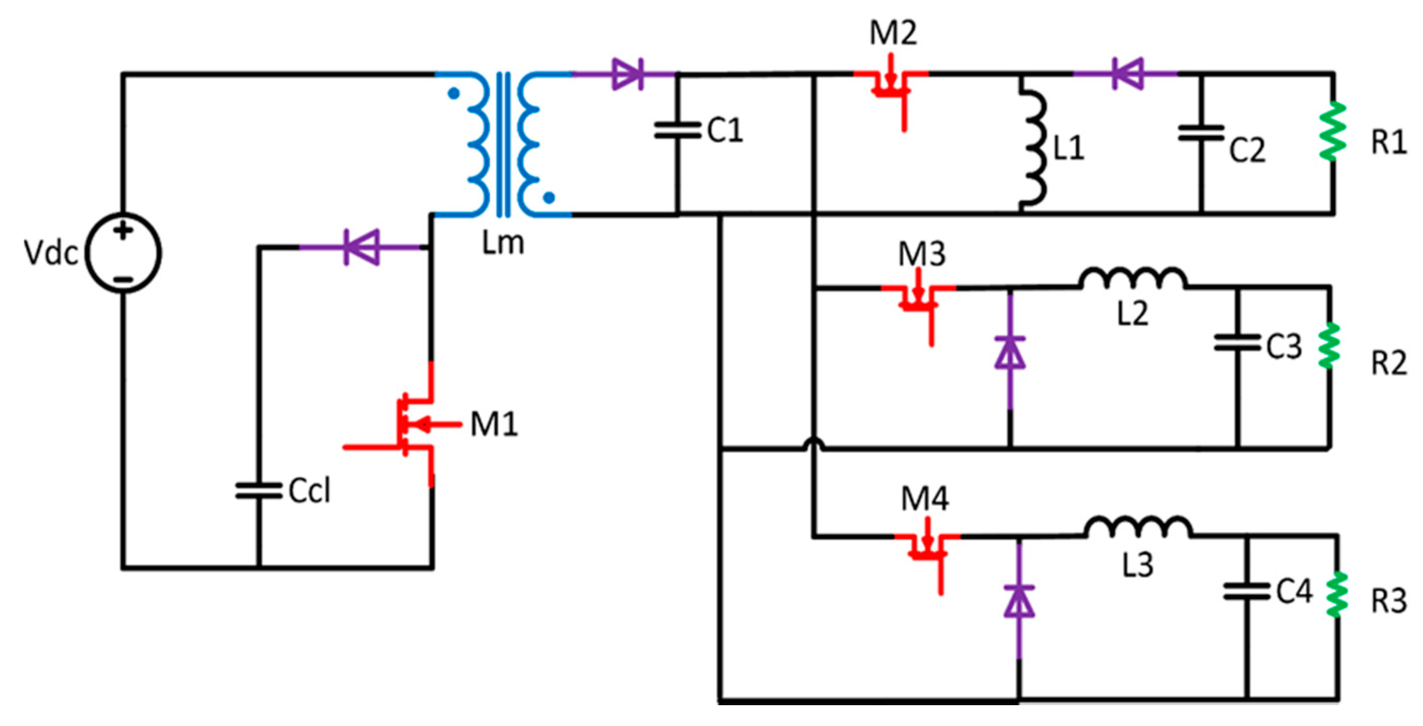
The input voltage Vdc of the DC microgrid is considered to be a solar panel whose output is expected to be 24 V. A 20 W, 12 V solar panel (54 × 46 cm) is used for implementing the solar array. To make the rated input to the grid, seven parallel connections of two series connected panels are used. The distribution losses in the microgrid can be reduced to a low value by stepping up the input voltage to a DC voltage of 72 V by a Flyback converter. A flyback converter is chosen for the proposed system as the primary side DC-DC converter for the purpose that it can facilitate galvanic seclusion in amongst the input and the DC microgrid. The specifications of the selected flyback converter are input voltage as 24 V, output voltage as 72 V and output power as 250 W. The simplicity of its topology compared to other isolated SMPS topologies is an added advantage. It also has the lesser component count and lowers cost, making it popular. This will function for an extensive difference of the source voltage, as well as, it can facilitate numerous secluded DC voltage outcomes.
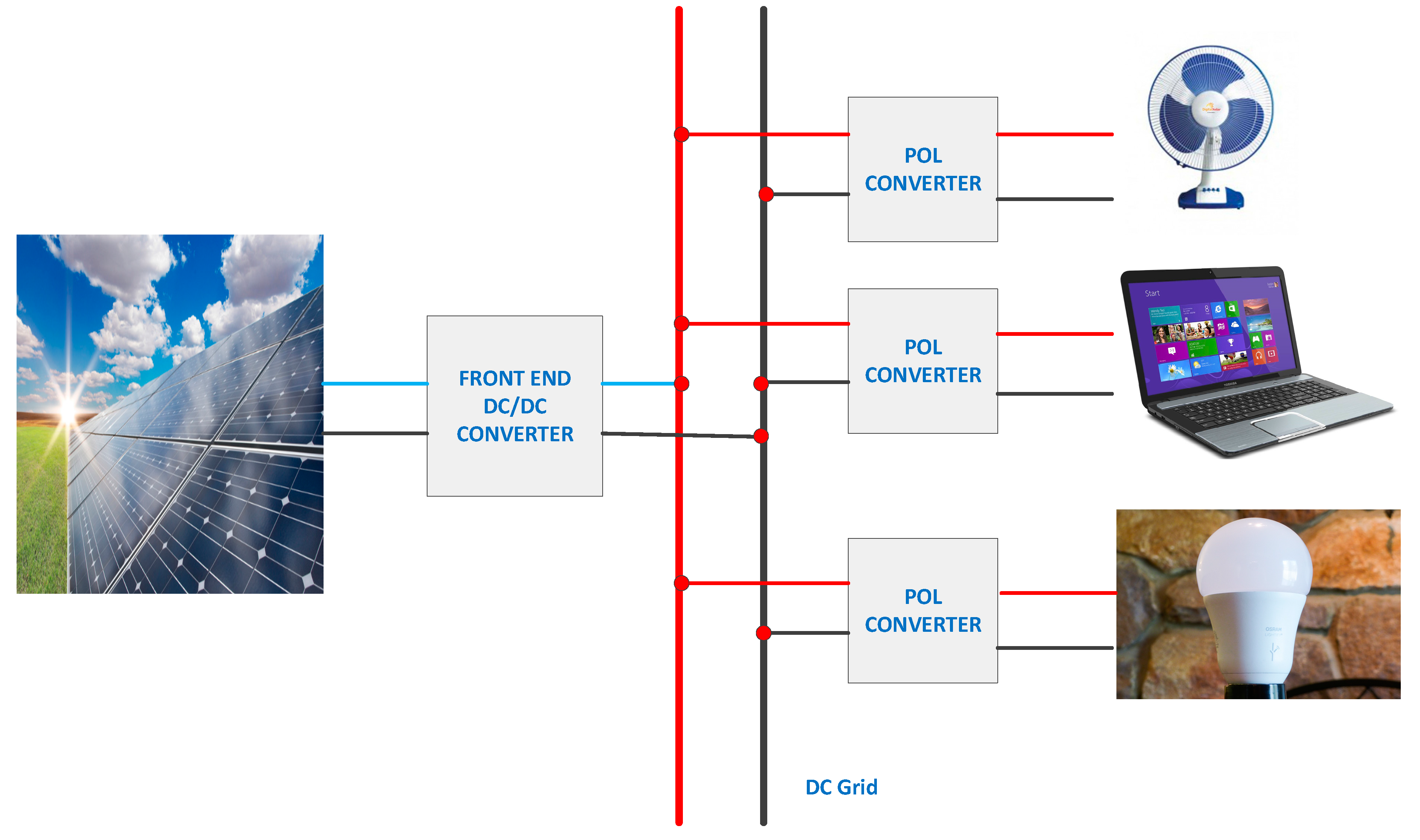
L, C and R denotes inductor, capacitor and resistor respectively. Lm denotes the mutual inductance. For an input voltage Vdc of 24 V and grid voltage Vgrd of 72 V, duty cycle ratio of the flyback converter is 0.42. The front end converter is designed to energize a cumulative device power of 250 W. Isolation transformer of turn’s ratio 1:4 is chosen for the proposed topology. The magnetizing inductance Lm of the isolation transformer is 85 µH. Switching frequency is selected as 50 KHz, and for a 1% voltage-ripple, capacitor C1 of 50 µF is used. A clamping circuit is also connected to the isolation transformer to absorb the energy stored in the inductor and provide a path for its dissipation to avoid high surge voltage. The capacitance Ccl of 1 µH is used in the clamping circuit. The microgrid voltage is fed to various devices by Point of Load (POL) converters [42]. Depending upon load specifications POL converters can be Buck-boost, Buck or Boost. Table 1 show various loads utilized by the proposed system. Figure 2 shows the proposed topology for the DC microgrid including the front end converter, bus and loads.
The circuit topology of the complete system including the front end converter, high voltage loads and low voltage loads are as shown in Figure 3. Here M1, M2, M3 and M4 are the controlled switches.
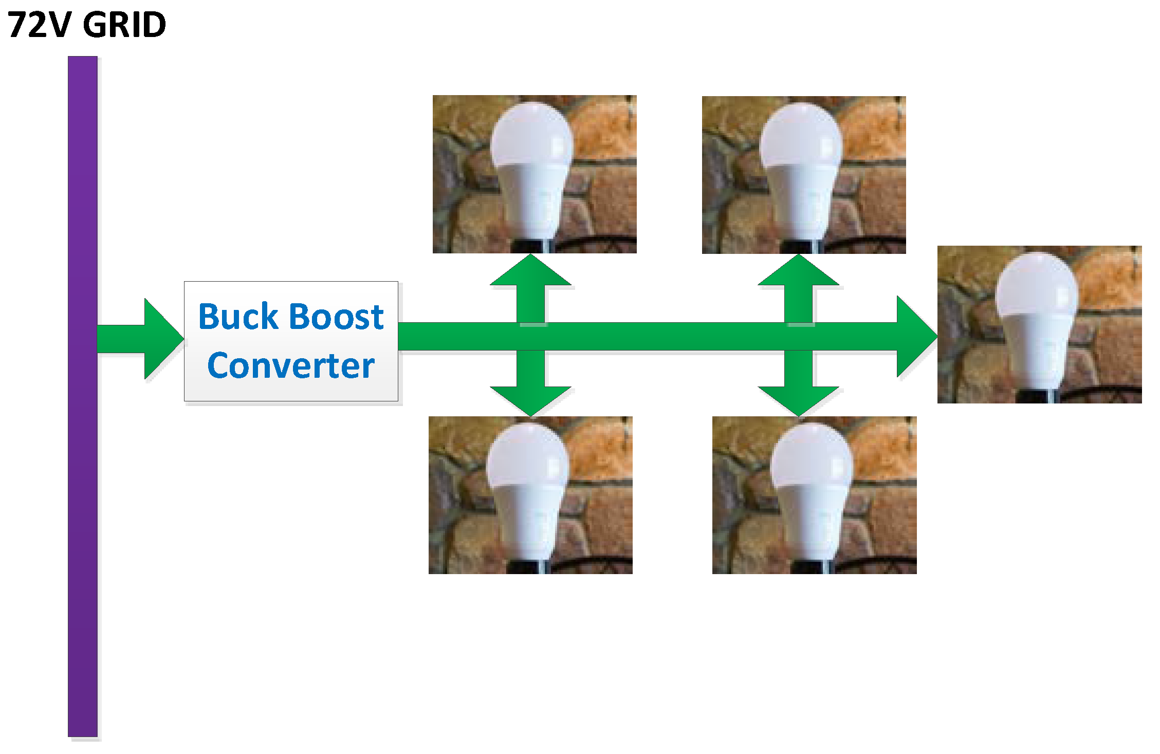
4. Loads with 24 V to 240 V Rating
The voltage essential for these loads is provided by a buck-boost voltage converter. For a home illuminating application, we are considering five 9 W Syska B22 LED bulb with 240 V DC voltage ratings. A buck-boost converter premeditated for a 1% peak voltage ripple and 10% current ripple of the rated voltage and current respectively. The proposed arrangement of the 24–240 V loads are illustrated in Figure 4. The designed values of inductor and capacitor is tabulated in Table 2.
5. Loads with <24 V Rating
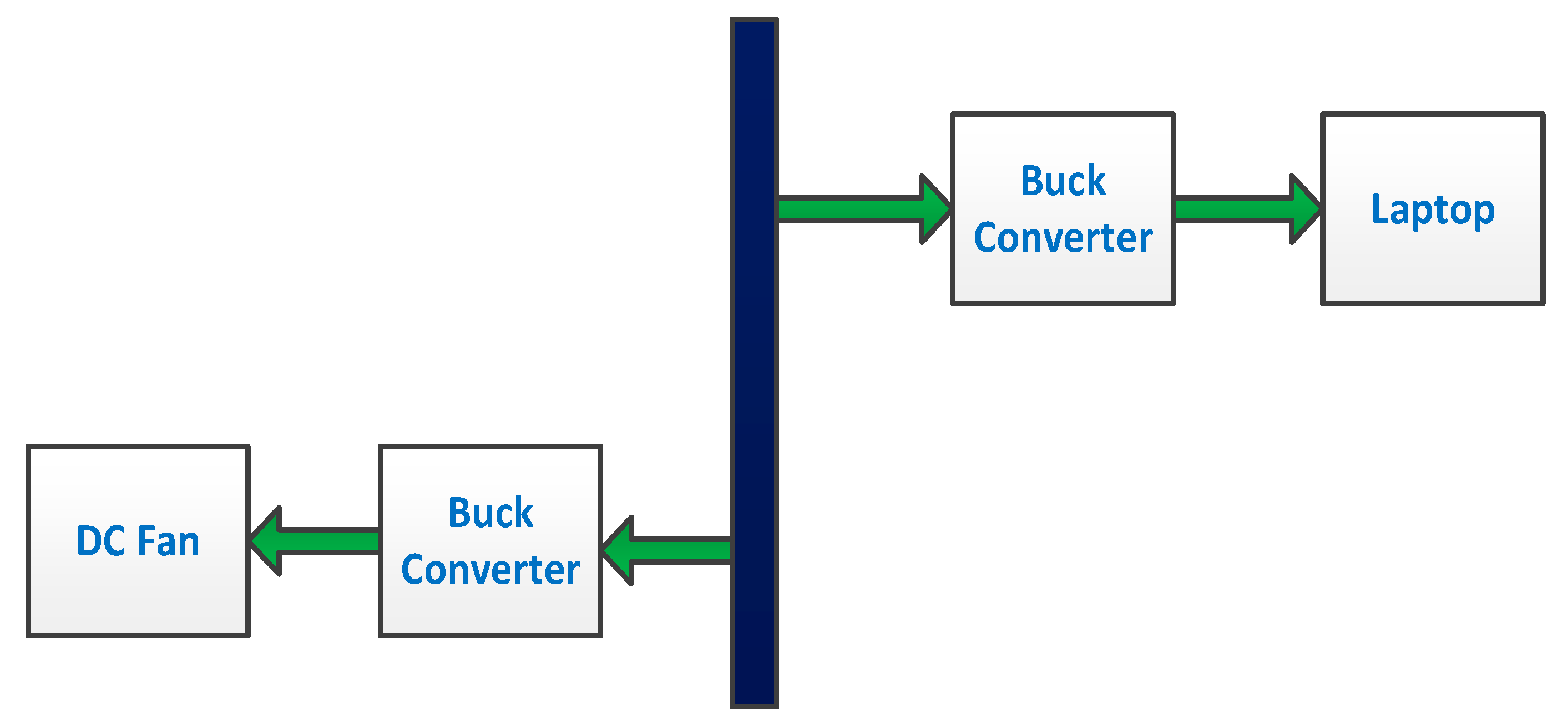
Low voltage loads like laptop and DC fan are considered in this section. Figure 5 above illustrates the designed connection diagram for the <24 V devices. These loads essentially need a ripple-free DC output voltage which is usually acquired by using high-efficient DC conversion stages followed by a stepping up PFC (power factor correction) circuit. This setup contributes bulkiness to the system [41]. By replacing the above mentioned circuitry with a steeping down buck converter, the power quality of the grid can be maintained with a minimized space consumption. This will reduces the development cost, dimensions and enhances the lifespan of the device [39]. In rural areas, usually the application side dispersal transformer having a 20% to 25% reduced voltage than the general fixed values. Operation of conventional induction motor based devices like household fans with such voltage variation from the general fixed values may results in higher iron losses, which may leads to the permanent damage of motor [8]. The calculated values of various converter parameters for energizing <24 V devices are tabulated in Table 2. Here VR1, VR2 and VR3 represents the voltage drop across <24 V loads R1, R2 and R3 respectively.
To mitigate these effects, modern brushless DC motors for DC fans can be used instead of conventional fans having less ripple percentage. In addition the reduction in losses, various advantages like improved power density, enhanced torque, higher life-span, and easy control and reduced maintenance cost.
6. Numerical Simulation Results
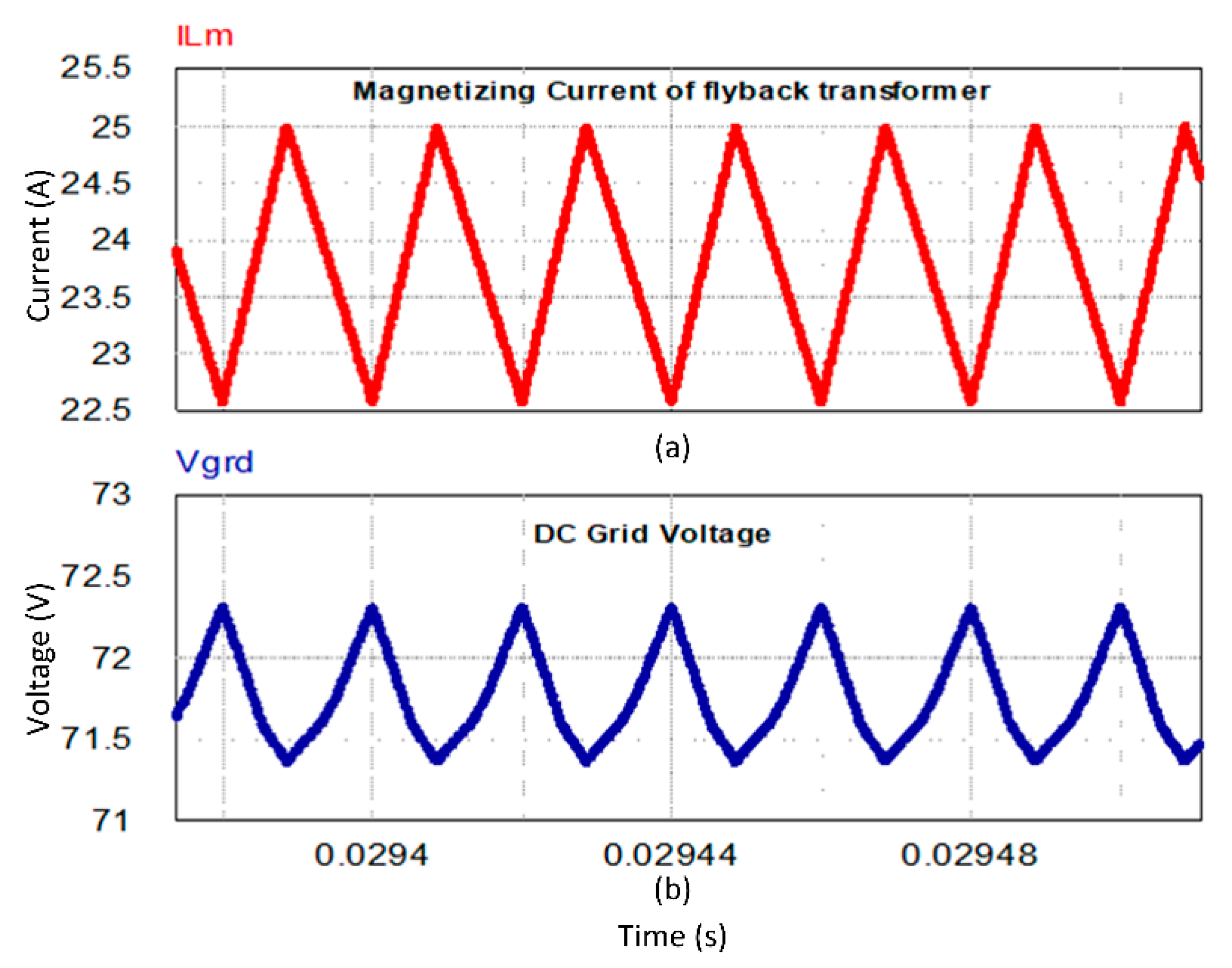
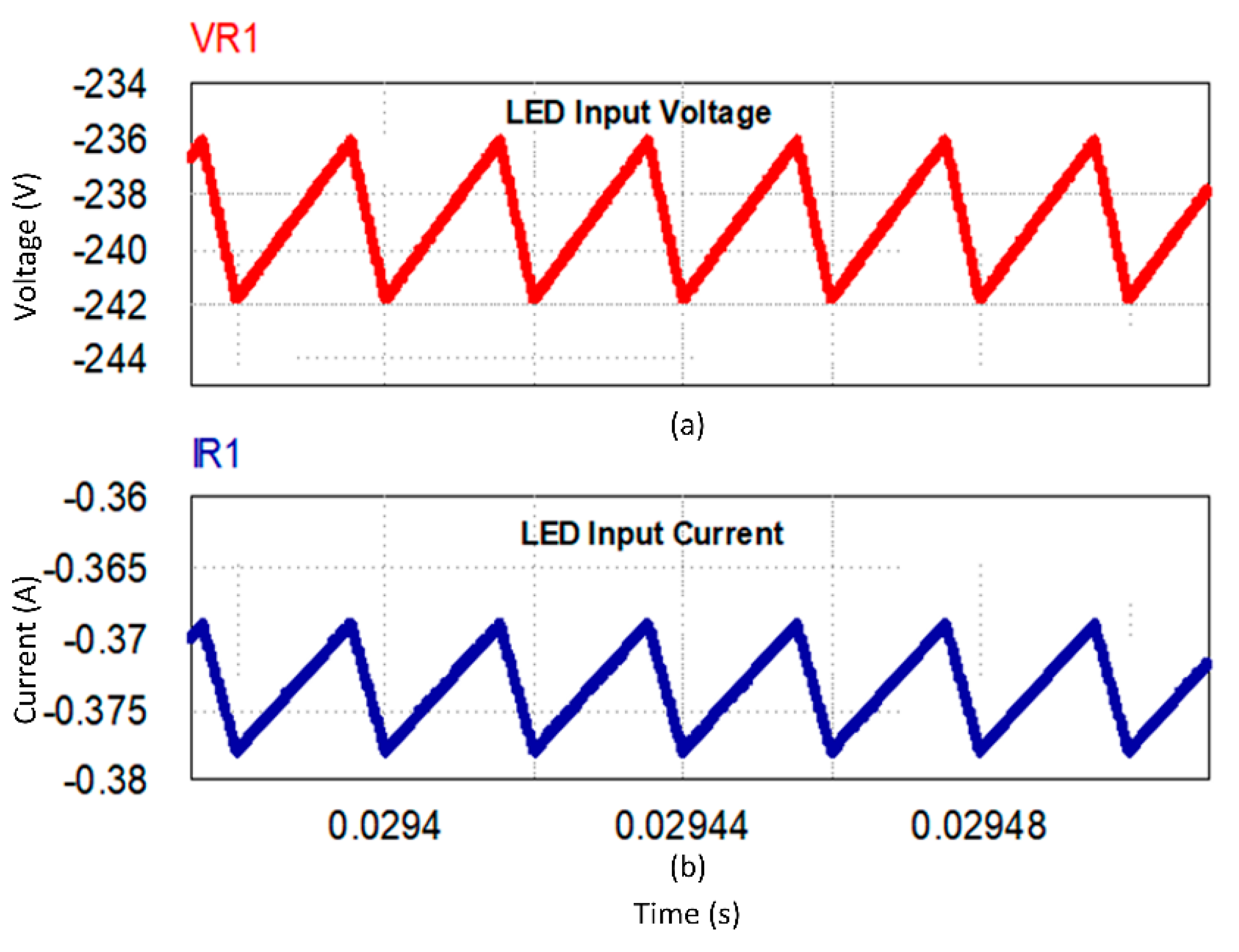
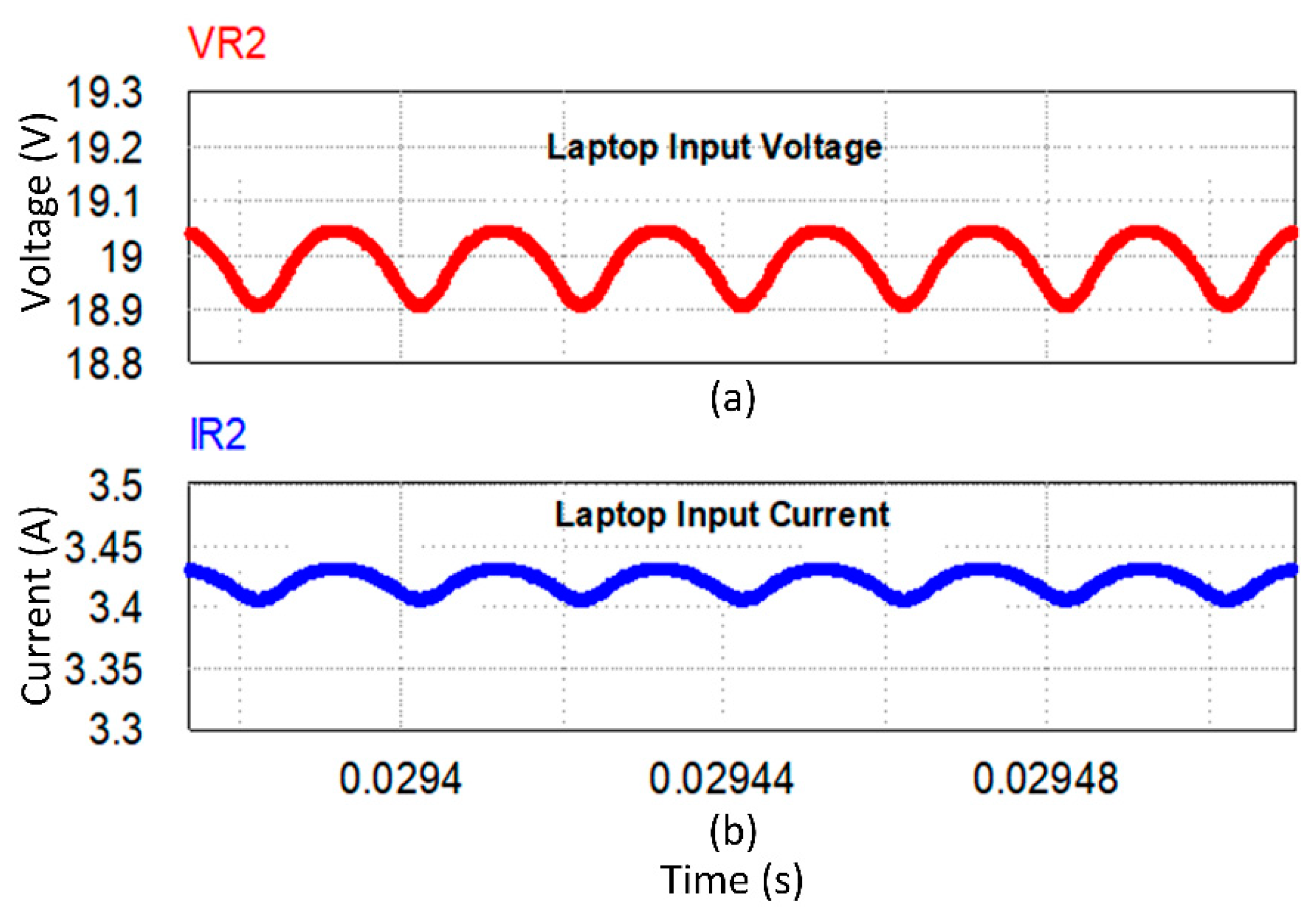
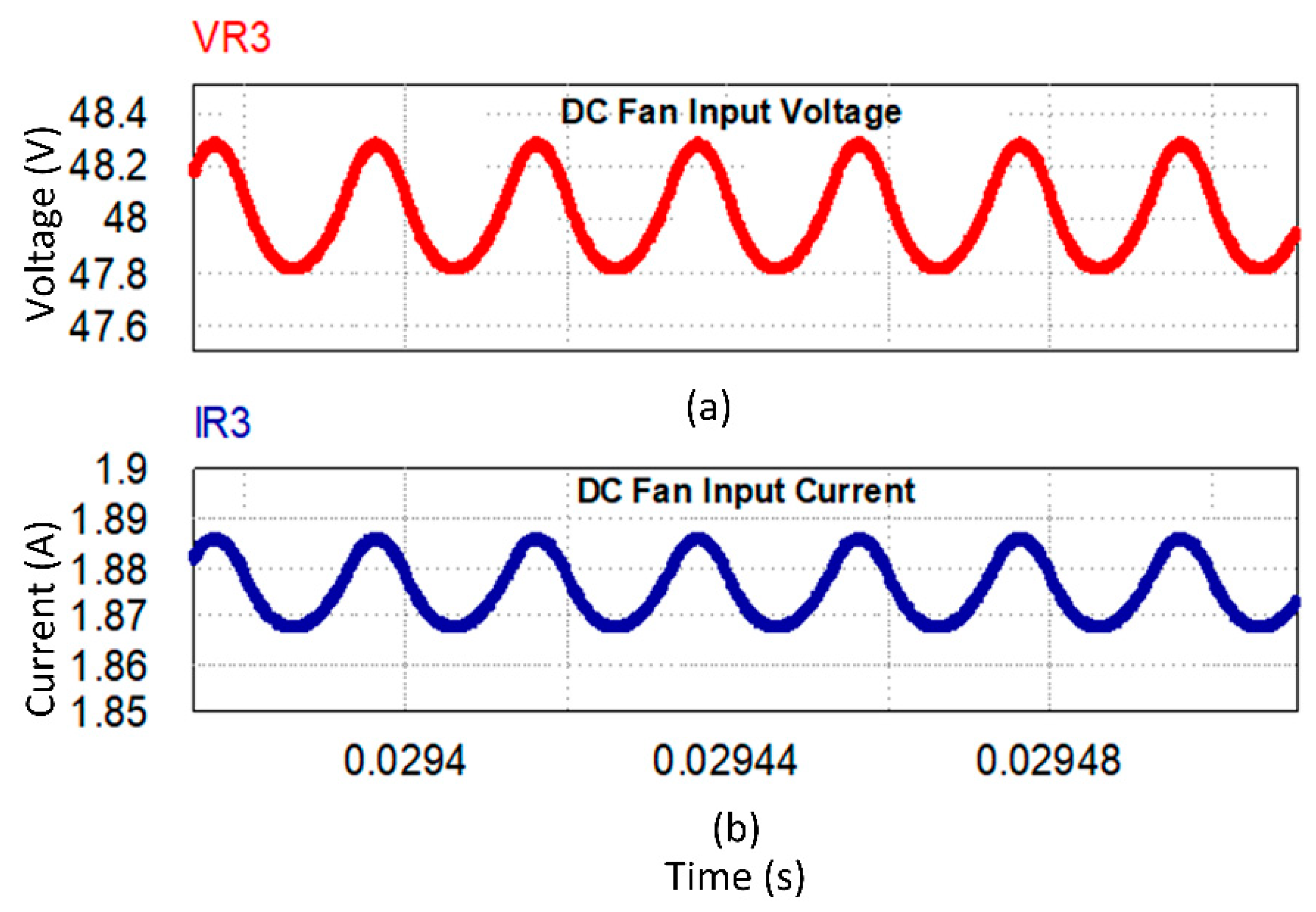
The PSIM Professional Version 9.1.1.400 (Vellore, Tamilnadu, India) was used to simulate the proposed system. The equivalent models of real time loads, devices and sources are used for the simulation. The simulated values of each loads are tabulated in Table 3. In this initial phase of research, simulated results are considered for formulating the conclusion. The flyback converter illustrated in Figure 3 is simulated to formulate the parameters. The system in total has four DC-DC converters. 72 V DC bus voltage used for the electrifying DC microgrid is obtained from front end converter as illustrated in Figure 6a. The magnetizing current waveforms from the flyback converter is shown in Figure 6b. Figure 6a illustrates the magnetizing current of the flyback transformer. The current ripple in the inductor magnetizing current is obtained as 9.64%. Figure 6b shows the DC grid voltage waveform. As the grid input is given by flyback converter, the grid voltage is 72 V as per the rating. The voltage ripple is obtained as 0.9%, which is feasible for a domestic power network. Figure 7a illustrates the LED input voltage waveform and Figure 7b shows the LED input current waveform. The voltage ripple and current ripple is obtained as 0.83% and 1.06% respectively. This reduced ripple denotes the high power quality of the microgrid. Figure 8a,b represents the laptop input voltage and current respectively from the grid. The waveforms are of high power quality. The voltage ripple and current ripple are obtained as 0.7% and 0.58% respectively. Similarly Figure 9a,b illustrates the DC fan input voltage and input current respectively. The voltage ripple and current ripple are found as 2.37% and 0.337% accordingly. From the waveforms of these loads, it is clear that the power quality of the proposed microgrid topology is very high compared to other conventional topologies.
7. Conclusions
This research proposes to design and simulation of a DC microgrid that facilitates standalone powering of a rural household which uses less than 250 W load from Solar PV array. The DC to DC POL conversion systems were effectively connected to a DC bus of 72 V. This grid is able to highlight the benefits that a DC grid arrangement have above the traditional AC grids, with a supreme advantage of reduced converter count at the device end. DC grid is designed to be 72 V as no fixed standards are available for this topology. The grid voltage on simulation is obtained as 72 V. The conversion circuitry for each device were developed and the prerequisite voltage values were attained from the systems. On observing the simulation results, it can be inferred that the designed DC grid can supply the rated power desirable for each load. By realizing on a higher scale, the scope of this project can be commercialized to power individual homes in an island area thereby achieving the goal of 0% unpowered villages.
Author Contributions
All authors contributed equally to the final dissemination of the research investigation as a full article.
Funding
This research activity received support from EEEIC International, Poland.
Acknowledgments
The authors would like to acknowledge the technical assistance received from the Center for Bioenergy and Green Engineering, Department of Energy Technology, Aalborg University, Denmark.
Conflicts of Interest
The authors declare no conflict of interest.
References
- Sieminski, A. Annual Energy Outlook 2015; US Energy Information Administration: Washington, DC, USA, 2015. [Google Scholar]
- Loomba, P.; Asgotraa, S.; Podmore, R. DC solar microgrids—A successful technology for rural sustainable development. In Proceedings of the IEEE PES Power Africa, Livingstone, Zambia, 28 June–2 July 2016; pp. 204–208. [Google Scholar]
- Jhunjhunwala, A.; Aditya, L.; Prabhjot, K. Solar-dc microgrid for Indian homes: A transforming power scenario. IEEE Electrif. Mag. 2016, 4, 10–19. [Google Scholar] [CrossRef]
- Chandel, S.S.; Shrivastva, R.; Sharma, V.; Ramasamy, P. Overview of the initiatives in renewable energy sector under the national action plan on climate change in India. Renew. Sustain. Energy Rev. 2016, 54, 866–873. [Google Scholar] [CrossRef]
- Makarabbi, G.; Gavade, V.; Panguloori, R.B.; Mishra, P.R. Compatibility and performance study of home appliances in a DC home distribution system. In Proceedings of the IEEE International Conference on Power Electronics, Drives and Energy Systems (PEDES), Mumbai, India, 16–19 December 2014. [Google Scholar]
- Rajesh, M.P.; Pindoriya, N.M.; Rajendran, S. Simulation of DC/DC converter for DC nano-grid integrated with solar PV generation. In Proceedings of the IEEE Innovative Smart Grid Technologies-Asia (ISGT ASIA), Bangkok, Thailand, 3–6 November 2015. [Google Scholar]
- Panguloori, R.B.; Mishra, P.R.; Boeke, U. Economic viability improvement of solar powered Indian rural banks through DC grids. In Proceedings of the Annual IEEE India Conference (INDICON), Hyderabad, India, 16–18 December 2011. [Google Scholar]
- Kaur, P.; Jain, S.; Jhunjhunwala, A. Solar-DC deployment experience in off-grid and near off-grid homes: Economics, technology and policy analysis. In Proceedings of the IEEE First International Conference on DC Microgrids (ICDCM), Atlanta, GA, USA, 7–10 June 2015; pp. 26–31. [Google Scholar]
- Global Buildings Performance Network. Residential Buildings in India: Energy Use Projections and Savings Potentials; Global Buildings Performance Network: Ahmedabad, India, 2014. [Google Scholar]
- Rodriguez-Diaz, E.; Vasquez, J.C.; Guerrero, J.M. Intelligent DC homes in future sustainable energy systems: When efficiency and intelligence work together. IEEE Consum. Electron. Mag. 2016, 5, 74–80. [Google Scholar] [CrossRef]
- Nilsson, D.; Sannino, A. Efficiency analysis of low and medium-voltage DC distribution systems. In Proceedings of the Power Engineering Society General Meeting, Denver, CO, USA, 6–10 June 2004; pp. 2315–2321. [Google Scholar]
- Rodriguez-Otero, M.A.; O’Neill-Carrillo, E. Efficient home appliances for a future DC residence. In Proceedings of the IEEE Energy 2030 Conference, Atlanta, GA, USA, 17–18 November 2008; pp. 1–6. [Google Scholar]
- Otero, R.; Angel, M. Power quality issues and feasibility study in a DC residential renewable energy system. Mast. Abstr. Int. 2009, 47. [Google Scholar]
- Sustainable Energy Program Report. The Use of Direct Current Output from PV Systems in Buildings. Available online: http://www.berr.gov.uk/files/file17277.pdf (accessed on 7 July 2008).
- Jeon, J.Y.; Kim, J.S.; Choe, G.Y.; Lee, B.K.; Hur, J.; Jin, H.C. Design guideline of DC distribution systems for home appliances: Issues and solution. In Proceedings of the IEEE International Electric Machines & Drives Conference (IEMDC), Niagara Falls, ON, USA, 15–18 May 2011; pp. 657–662. [Google Scholar]
- Center for Decentralized Power Systems. Technological Comparative Study of Solar Lighting Systems for Homes; Indian Institute of Technology: Chennai, India, 2015. [Google Scholar]
- Rodriguez-Diaz, E.; Savaghebi, M.; Vasquez, J.C.; Guerrero, J.M. An overview of low voltage DC distribution systems for residential applications. In Proceedings of the 5th International Conference on Consumer Electronics-Berlin (ICCE-Berlin), Berlin, Germany, 6–9 September 2015; pp. 318–322. [Google Scholar]
- Vossos, E. Optimizing Energy Savings from “Direct-DC” in US Residential Buildings; Ernest Orlando Lawrence Berkeley National Laboratory: Berkeley, CA, USA, 2011. [Google Scholar]
- Vossos, V.; Garbesi, K.; Shen, H. Energy savings from direct-DC in US residential buildings. Energy Build. 2014, 68, 223–231. [Google Scholar] [CrossRef]
- Savage, P.; Nordhaus, R.R.; Jamieson, S.P. Dc Microgrids: Benefits and Barriers. In From Silos to Systems: Issues in Clean Energy and Climate Change; Yale School of Forestry & Environmental Studies: New Haven, CT, USA, 2010; pp. 51–66. [Google Scholar]
- Koutroulis, E.; Kalaitzakis, K.; Voulgaris, N.C. Development of a microcontroller-based, photovoltaic maximum power point tracking control system. IEEE Trans. Power Electr. 2001, 16, 46–54. [Google Scholar] [CrossRef]
- Tong, Y.; Shan, Z.; Jatskevich, J.; Davoudi, A. A nonisolated multiple-input-multiple-output dc-dc converter for dc distribution of future energy efficient homes. In Proceedings of the IECON 2014—40th Annual Conference of the IEEE Industrial Electronics Society, Dallas, TX, USA, 30 October–1 November 2014; pp. 4126–4132. [Google Scholar]
- Weiss, R.; Ott, L.; Boeke, U. Energy-efficient low-voltage DC-grids for commercial buildings. In Proceedings of the IEEE First International Conference on DC Microgrids (ICDCM), San Francisco, CA, USA, 30 March–3 April 2015; pp. 154–158. [Google Scholar]
- Tidjani, F.S.; Chandra, A. Integration of renewable energy sources and the utility grid with the Net Zero Energy Building in the Republic of Chad. In Proceedings of the IECON 2012—38th Annual Conference on IEEE Industrial Electronics Society, Montreal, CA, USA, 25–28 October 2012; pp. 1025–1030. [Google Scholar]
- Rajaraman, V.; Jhunjhunwala, A.; Kaur, P.; Rajesh, U. Economic analysis of deployment of DC power and appliances along with solar in urban multi-storied buildings. In Proceedings of the IEEE First International Conference on DC Microgrids (ICDCM), Atlanta, GA, USA, 24–27 May 2015; pp. 32–37. [Google Scholar]
- Momose, T.; Osaka Gas Company Limited, Japan. Nano-grid: Small scale DC Microgrid for Residential Houses with Cogeneration System in Each House. In Proceedings of the International Gas Union Research Conference, Paris, France, 8–10 October 2008; Currans Associates, Inc.: Red Hook, NY, USA, 2008. [Google Scholar]
- Sasidharan, N.; Singh, J.G. A Novel Single-Stage Single-Phase Reconfigurable Inverter Topology for a Solar Powered Hybrid AC/DC Home. IEEE Trans. Ind. Electr. 2017, 64, 2820–2828. [Google Scholar] [CrossRef]
- Sun, K.; Wang, X.; Qiu, Z.; Wu, H.; Xing, Y. A PV generation system based on the centralized-distributed structure and cascaded power balancing mechanism for DC microgrids. In Proceedings of the IEEE 2nd International Future Energy Electronics Conference (IFEEC), Taipei, Taiwan, 1–4 November 2015; pp. 1–6. [Google Scholar]
- Shwehdi, M.H.; Mohamed, S.R. Proposed smart DC nano-grid for green buildings—A reflective view. In Proceedings of the International Conference on Renewable Energy Research and Application (ICRERA), Milwaukee, WI, USA, 19–22 October 2014; pp. 765–769. [Google Scholar]
- Stieneker, M.; De Doncker, R.W. Medium-voltage DC distribution grids in urban areas. In Proceedings of the IEEE 7th International Symposium on Power Electronics for Distributed Generation Systems (PEDG), Vancouver, BC, Canada, 27–30 June 2016; pp. 1–7. [Google Scholar]
- Friedman, M.M.; van Timmeren, A.; Boelman, E.; Schoonman, J. The concept for a dc low voltage house. Smart Sustain. Built Environ. 2008, 85–94. [Google Scholar]
- Li, W.; Mou, X.; Zhou, Y.; Marnay, C. On voltage standards for DC home microgrids energized by distributed sources. In Proceedings of the 7th International Power Electronics and Motion Control Conference (IPEMC), Harbin, China, 2–5 June 2012; Volume 3, pp. 2282–2286. [Google Scholar]
- Starke, M.; Tolbert, L.M.; Ozpineci, B. AC vs. DC Distribution: A loss comparison. In Proceedings of the IEEE/PES Transmission and Distribution Conference and Exposition, Chicago, IL, USA, 21–24 April 2008; pp. 1–7. [Google Scholar]
- Pratt, A.; Kumar, P.; Aldridge, T.V. Evaluation of 400V DC distribution in telco and data centers to improve energy efficiency. In Proceedings of the INTELEC 2007—29th International Telecommunications Energy Conference, Rome, Italy, 30 September–4 October 2007; pp. 32–39. [Google Scholar]
- Ammerman, R.F.; Gammon, T.; Sen, P.K.; Nelson, J.P. DC arc models and incident energy calculations. In Proceedings of the Record of Conference Papers Industry Applications Society 56th Annual Petroleum and Chemical Industry Conference, Anaheim, CA, USA, 14–16 September 2009; pp. 1–13. [Google Scholar]
- Baran, M.E.; Mahajan, N.R. DC distribution for industrial systems: Opportunities and challenges. IEEE Trans. Ind. Appl. 2003, 39, 1596–1601. [Google Scholar] [CrossRef]
- Manandhar, U.; Ukil, A.; Jonathan, T.K.K. Efficiency comparison of DC and AC microgrid. In Proceedings of the IEEE PES Innovative Smart Grid Technologies Conference—Asia (ISGT Asia), Bangkok, Thailand, 3–6 November 2015; pp. 1–6. [Google Scholar]
- Jagadish Kumar Patra, H.M.; Tania, D.E.; Arunkumar, G. A Review on Advancements in DC Microgrid Technology. Proc. Today 2016, 9, 1265–1279. [Google Scholar]
- Wunder, B.; Ott, L.; Szpek, M.; Boeke, U.; Weiß, R. Energy efficient DC-grids for commercial buildings. In Proceedings of the IEEE 36th International Telecommunications Energy Conference (INTELEC), Vancouver, BC, Canada, 28 September–2 October 2014; pp. 1–8. [Google Scholar]
- Umanand, L. Power Electronics—Essentials and Applications; Wiley India Pvt. Ltd.: New Delhi, India, 2009. [Google Scholar]
- Rykov, K.; Duarte, J.L.; Szpek, M.; Olsson, J.; Zeltner, S.; Ott, L. Converter impedance characterization for stability analysis of low-voltage DC-grids. In Proceedings of the IEEE PES Innovative Smart Grid Technologies Asia (ISGT Asia), Washington, DC, USA, 19–22 February 2014; pp. 1–5. [Google Scholar]
- Carli, R.; Dotoli, M. Energy scheduling of a smart home under nonlinear pricing. In Proceedings of the 53rd IEEE Conference on Decision and Control, Los Angeles, CA, USA, 15–17 December 2014; pp. 5648–5653. [Google Scholar]
- Sperstad, I.B.; Korpås, M. Energy Storage Scheduling in Distribution Systems Considering Wind and Photovoltaic Generation Uncertainties. Energies 2019, 12, 1231. [Google Scholar] [CrossRef]
- Hosseini, S.M.; Carli, R.; Dotoli, M. Model Predictive Control for Real-Time Residential Energy Scheduling under Uncertainties. In Proceedings of the 2018 IEEE International Conference on Systems, Man, and Cybernetics (SMC), Miyazaki, Japan, 7–10 October 2018; pp. 1386–1391. [Google Scholar]
- Wu, Y.; Lau, V.K.; Tsang, D.H.; Qian, L.P.; Meng, L. Optimal energy scheduling for residential smart grid with centralized renewable energy source. IEEE Syst. J. 2013, 8, 562–576. [Google Scholar] [CrossRef]
- Carli, R.; Dotoli, M. A decentralized resource allocation approach for sharing renewable energy among interconnected smart homes. In Proceedings of the 54th IEEE Conference on Decision and Control (CDC), Osaka, Japan, 15–18 December 2015; pp. 5903–5908. [Google Scholar]
- Sun, L.; Wu, G.; Xue, Y.; Shen, J.; Li, D.; Lee, K.Y. Coordinated control strategies for fuel cell power plant in a microgrid. IEEE Trans. Energy Convers. 2017, 33, 1–9. [Google Scholar] [CrossRef]
- Patterson, M.; Macia, N.F.; Kannan, A.M. Hybrid microgrid model based on solar photovoltaic battery fuel cell system for intermittent load applications. IEEE Trans. Energy Convers. 2014, 30, 359–366. [Google Scholar] [CrossRef]
- Farrokhabadi, M.; König, S.; Cañizares, C.A.; Bhattacharya, K.; Leibfried, T. Battery energy storage system models for microgrid stability analysis and dynamic simulation. IEEE Trans. Power Syst. 2017, 33, 2301–2312. [Google Scholar] [CrossRef]
Figure 1.
Methodology outline.

Figure 2.
Proposed Schematic for the proposed circuit topology.

Figure 3.
Complete circuit topology including front end Flyback converter for 0–240 V loads.

Figure 4.
Proposed arrangement for 24–240 V Devices.

Figure 5.
Proposed arrangement for <24 V devices.

Figure 6.
Output of Simulation DC-Grid Voltage. Average Voltage = 71.6 V, voltage ripple = 0.9% and output of Simulation—magnetizing inductor current. Average inductor current 24.39 A, current ripple = 9.64%. (a) Magnetizing current of flyback converter; (b) DC grid voltage.
Figure 6.
Output of Simulation DC-Grid Voltage. Average Voltage = 71.6 V, voltage ripple = 0.9% and output of Simulation—magnetizing inductor current. Average inductor current 24.39 A, current ripple = 9.64%. (a) Magnetizing current of flyback converter; (b) DC grid voltage.

Figure 7.
LED Input Voltage and Current Waveforms. LED Input Voltage Ripple: 0.83% Current Ripple: 1.06%. (a) LED input voltage; (b) LED input current.
Figure 7.
LED Input Voltage and Current Waveforms. LED Input Voltage Ripple: 0.83% Current Ripple: 1.06%. (a) LED input voltage; (b) LED input current.

Figure 8.
Laptop Input Voltage and Current Waveform. Laptop Input Voltage Ripple: 0.7%; Current Ripple: 0.58%. (a) Laptop input voltage; (b) Laptop input current.
Figure 8.
Laptop Input Voltage and Current Waveform. Laptop Input Voltage Ripple: 0.7%; Current Ripple: 0.58%. (a) Laptop input voltage; (b) Laptop input current.

Figure 9.
DC Fan Load Input Voltage and Current Waveform. DC Fan Input Voltage Ripple: 2.37%; Current Ripple: 0.337%. (a) DC fan input voltage; (b) DC fan input current.
Figure 9.
DC Fan Load Input Voltage and Current Waveform. DC Fan Input Voltage Ripple: 2.37%; Current Ripple: 0.337%. (a) DC fan input voltage; (b) DC fan input current.


Table 1.
Loads selected for the analysis of work.
| Device | Wattage (W) | Rated Voltage(V) |
|---|---|---|
| DC FAN | 90 | 48 |
| LAPTOP | 65 | 19 |
| LED | 5 × 18 (90) | 240 |
Table 2.
Calculated values of various converter parameters for energizing LV devices.
| Device | Duty Formula, (D) | Duty | Converter | Inductance | Capacitance |
|---|---|---|---|---|---|
| LED LIGHTS (R1) | 0.769 | Buck-Boost | L1: 24.3 mH | C2: 5 µF | |
| DC FAN (R2) | 0.667 | Buck | L2: 1.69 mH | C3: 1 µF | |
| LAPTOP CHARGER (R3) | 0.263 | Buck | L3: 1 mH | C4: 5µF |
Table 3.
Output voltages and currents of each load.
| Load | Vbus (V) | Duty Cycle Formula, (D) | Duty Cycle (D) | Vout (V) | It (A) |
|---|---|---|---|---|---|
| LED LIGHTS | 71.66 | 0.769 | 239.7 | 0.375 | |
| DC FAN | 71.66 | 0.667 | 47.9 | 1.87 | |
| LAPTOP CHARGER | 71.66 | 0.263 | 19.8 | 3.41 |
© 2019 by the authors. Licensee MDPI, Basel, Switzerland. This article is an open access article distributed under the terms and conditions of the Creative Commons Attribution (CC BY) license (http://creativecommons.org/licenses/by/4.0/).
Share and Cite
MDPI and ACS Style
Arunkumar, G.; Elangovan, D.; Sanjeevikumar, P.; Nielsen, J.B.H.; Leonowicz, Z.; Joseph, P.K. DC Grid for Domestic Electrification. Energies 2019, 12, 2157. https://doi.org/10.3390/en12112157
AMA Style
Arunkumar G, Elangovan D, Sanjeevikumar P, Nielsen JBH, Leonowicz Z, Joseph PK. DC Grid for Domestic Electrification. Energies. 2019; 12(11):2157. https://doi.org/10.3390/en12112157
Chicago/Turabian StyleArunkumar, G., D. Elangovan, P. Sanjeevikumar, Jens Bo Holm Nielsen, Zbigniew Leonowicz, and Peter K. Joseph. 2019. "DC Grid for Domestic Electrification" Energies 12, no. 11: 2157. https://doi.org/10.3390/en12112157
Note that from the first issue of 2016, this journal uses article numbers instead of page numbers. See further details here.