Internal Flow Analysis of a Heat Transfer Enhanced Tube with a Segmented Twisted Tape Insert


1
State Key Laboratory of Fluid Power and Mechatronic Systems, Zhejiang University, Hangzhou 310027, China
2
Institute of Process Equipment, College of Energy Engineering, Zhejiang University, Hangzhou 310027, China
*
Authors to whom correspondence should be addressed.
Energies 2020, 13(1), 207; https://doi.org/10.3390/en13010207
Submission received: 31 October 2019
/
Revised: 8 December 2019
/
Accepted: 25 December 2019
/
Published: 1 January 2020
Abstract
:A heat exchanger is a device that transfers unneeded heat from one region to another, and transferred heat may be fully reused, thus improving energy efficiency. To augment this positive process, many studies and investigations on automation technologies have been performed. Inserts are widely used in pipe flow for heat transfer enhancement, since they can break the boundary layer and promote the heat exchange. Segmented twisted tape, which is applicable in 3D printing, is a novel insert and has potential in heat transfer enhancement. To clarify its advantages and disadvantages, this research presents a numerical investigation of vortex flow and heat enhancement in pipes containing one segmented twisted element. Flow state and heat transfer behaviour are obtained by simulation under constant wall temperature with different Reynolds numbers, ranging from 10,000 to 35,000. The effects of geometric parameters, including twist ratio (P/D = 2.0, 3.3 and 4.6) and length ratio (L/P = 0.3, 0.5 and 0.7), on the Nusselt number (Nu) and friction factor (f) are investigated. Streamline and temperature distribution are presented. Meanwhile, local and overall heat transfer performance is compared with those of a smooth tube, and the overall performance is evaluated by performance evaluation factor (η). The results indicate that the twist ratio (P/D) plays a dominant role in heat transfer enhancement while the length ratio (L/P) also has considerable influence. It is shown that a segmented tape insert can increase the overall heat transfer rate by 23.5% and the friction factor by 235%, while local improvement along the tube can be 2.8 times more than the plain tube.
1. Introduction
With the purpose of cooling or heating, transferred heat or excess heat from one region may be reused and contribute positively to the energy efficiency of a system; thus, heat exchangers are widely utilised. They can easily be found in chemical and petroleum plants, process engineering and civil heating system as well. Heat exchangers can be classified into several groups according to geometric configuration, although improving the heat transfer performance is the common goal. Over the last 50 years, the single-phase pipe exchanger has seen a variety of augmentation techniques, and the heat transfer capacity has been improved greatly [1,2,3,4,5,6,7,8]. Among various studies carried out on pipe flow enhanced technologies, adopting the insert inside a tube is a common approach.
Increasing the effective working surface can increase the heat flux in a relatively compact size and is often adopted as a practical way to improve heat transfer capacity. Open-cell foam is one kind of solid material with connected pores inside, which provide liquid with space and channels to flow through. With the advantage of large surface-to-volume ratio that can reach up to 10,000 m2/m3 in particular structure configurations [9], it has been employed as a pipe insert to increase the effective surface in the heat exchanger. However, it is generally recommended for low-Reynolds-number fluids, as its high thermal performance is often offset by high head loss [10,11,12]. Besides, uncontrollable size and diameter largely depend on the manufacturing process, which makes it hard to build solid theory. Lacroix et al. estimated the pressure drop of pipes using a simplified model for a cubic unit cell but with a good agreement with experimental results [13]. With the advantage of 3D printing (3DP), the periodic cellular structure is regarded as a promising insert to enhance the heat transfer performance by two-fold advantages, such as large surface area and low-pressure drop. Busse et al. designed periodic open cellular structures (POCS) and carried out a comparative analysis with the randomly packed bed, open-cell foam and honeycomb [14]. They studied material, morphology and wall coupling of POCS, and the result showed that POCS outperform others, particularly at a low flow rate. In reference to stochastic open-cell foams, another octet truss lattice (OTL) structure with a 12 node connection was proposed by Chaudhari et al. [15]. They investigated the effect of porosity on thermal conductivity, permeability, inertial coefficient, friction factor and Nusselt number, and a correlation was also established. The experimental investigation proved that OTL is a possible alternative in heat exchanger/sink in consideration of low pressure drop.
Swirling flow has been verified as another effective method to increase the heat transfer capacity in convective systems, and some in-tube elements were designed to generate a swirling flow or vortex. A twisted strip inside a tube can function as a vortex generator and create a significant enhancement for turbulent or laminar flow in a single-phase convection process. Numerous studies have been carried out to investigate the thermal enhancement and the cost of swirling flow inside a tube. Adopting the performance evaluation criteria presented in [16], Ji et al. [17] compared different enhancement technologies and found that turbulence promoters have higher enhanced ratios than other passive technologies. The same result can be observed in [18], and the enhancement ratio under the identical pressure drop criteria reached 2.8, which was nearly doubled that of other inserts. To improve the flow pattern and promote turbulence further, additional geometric patterns on tape surfaces have been investigated. Wijayanta et al. carried out numerical studies on the thermal improvement of pipe flow using tape with two-sided delta winglets or square cuts, and the results were encouraging [19,20]. Chang et al. discussed the pros and cons of repeated ribs on tape surfaces [21]. They also investigated the effects that the number of twisted inserts had on frictional loss and augmentation ratio [22]. Wongcharee and Eiamsa-ard clarified the influence of additional tape features like alternate axes and wings in different shapes [23], while the performance of twisted tape with axial holes was reported by Thianpong et al. [24]. Combining different enhancement technologies is also preferable; the characteristics of a corrugated tube with different forms of twisted tape inserts can be found in [25], and it guaranteed a better overall performance compared to the single augmentation method.
The length and installation arrangement of twisted tapes have been studied by many researchers. Manglik and Bergles tested and recorded the friction factor and heat transfer enhancement of full-length twist tapes and presented correlation formulae suitable for transitional and fully developed flow [26]. An expanded investigation was carried out by Hong et al., in which full and half-length twisted tape with different pitches were studied [27]. Compared to smooth tubes, the encouraging results showed that both the Nusselt number and friction factor are strong functions of the twist ratio. In order to obtain a higher Nusselt number with a relatively small pressure drop, Saha et al. designed evenly spaced twisted-tape elements and discussed heat transfer and pressure drop characteristics in Reynolds numbers ranging from 500 to 2300 [28]. However, a clear and assertive conclusion did not come out, as partially inserted twisted tape did not always have superior performance than the full-length one, and even the pumping power reduction could reach up to 40% at the fixed heat duty. Similar research can be found in [29], and the correlation was proposed for practical application. Even though they provided direct evidence of its capacity in heat exchange augmentation and low pressure loss for this arrangement, they could not exclude the influence of the central rod used to connect single elements in a spaced twisted tape. On top of that, a loose fit between the inserts and the pipe wall could weaken the heat transfer ability [30,31]. In other words, their design freedom may be limited by manufacturing technology in the above-mentioned research. It is hard or even impossible for traditional manufacturing to fix one single insert inside a tube at the location as desired without a rod connection, and also the gap between insert and walls is uncontrollable. As a consequence, there are few publications about segmented twisted tape, and more detailed investigation is needed.
Adopting the idea of 3DP, the enhanced tube assembly conventionally consisting of pipes and inserts can be printed as a single part, and the insert element can be added at any location with controllable clearance but without any additional mechanical connection. Actually, there are some researchers utilising 3DP to realise a complex internal fluid guiding element and membrane in a compact heat exchanger, which are not applicable using conventional manufacturing methods [32,33]. Whereas there is limited research about the 3DP-optimized twisted tape insert, this article investigates the geometric features of a single insert element that is achievable by 3DP, and hopefully provides some reference for related research.
2. Geometric Model
After being processed in a rolling operation, the twisted tape offers smooth and continuous curved surfaces inside a tube. For evenly distributed twisted tape shown in Figure 1a, the single insert element is connected by a central rod, of which the diameter d is around 25% of the inner diameter of tube D. The length of twisted tape h and free space s are two main design parameters and the space lengths are usually constant among elements. As for the geometry under investigation in Figure 1b, it puts much emphasis on the geometry design of single element and its consequential effect on heat transfer. Different from traditional design, a central rod is not necessary any longer to fix the insert to the wall at a specific location, because the 3DP can print them into one single part.
Twist ratio P/D and length ratio L/P are two geometric features of interest, where P denotes the length of a twisted unit and L presents the actual length of pipe insert. Setting D as 10 mm, three different twist ratios (P/D = 2.0, 3.3, 4.6) are designed, and three models with different length ratios (L/P = 0.3, 0.5, 0.7) are proposed at every P/D. A constant wall thickness of 0.67 mm is designed, and a smooth transition is added to the two tape ends. The tube in this research is 1000 mm long, and the segmented twisted tape is inserted 100 mm away from the inlet port, which can guarantee a fully developed flow.
3. Numerical Method
This research involves the investigation of flow state and heat transfer behaviour, so a finite difference method for turbulence is employed to solve the governing partial equations. It is necessary to make some fundamental assumptions before applying the universal flow equations and energy equation to the tube with vortex generators. The major assumptions include the following: (a) the fluid through the tube is incompressible, (b) the thermal–physical property is temperature independent and (c) the heat loss caused by radiation and natural convection is neglected.
On the basis of the stated assumptions, a proper governing equation is employed to describe the steady-state thermal condition and time-invariant fluid flow. The time-averaged impressible Navier–Stokes equations for three-dimensional models in Cartesian form can be expressed as follows:
Continuity equation:
Momentum equation:
Energy equation:
A proper partial differential equation should be selected according to the complexity of the fluid domain, and generally, a balance between accuracy and computational cost is desired. The Navier–Stokes equation is widely accepted as it can reflect the actual fluid situation accurately in most cases, whereas this accuracy is offset by the cost of computational sources. Separating time-dependent turbulent velocity fluctuations from the mean flow velocity, a modified Reynolds Average Navier–Stokes (RANS) model makes it possible to simulate practical engineering flows. However, this will introduce Reynolds stresses that are related to fluctuation terms in the velocity field. Employing the Boussinesq hypothesis, the Reynolds stresses in Equation (2) can be expressed as Equation (5).
The turbulent viscosity term μt in Equation (5) can be obtained in Equation (6).
In consideration of sudden geometry change within the tube, the incompressible Navier–Stokes equation along with the realisable k-ε turbulence model is discretized using the finite volume technique. Water is chosen as the working fluid, and the time-independent physical property of water at 20 °C is listed as follows: density 998.2 kg/m3, specific heat 4182 J/(kg·K), thermal conductivity 0.601 W/(m·K) and dynamic viscosity 1.003 mPa·s. To inspect the pressure distribution, the pressure–velocity coupling algorithm SIMPLE is selected. A second-order scheme is utilised in pressure, momentum, turbulent terms and energy, while a least-squares cell based spatial discretization is used in the gradient. The turbulent intensity is kept at 5% at the inlet while the hydraulic diameter is fixed at 10 mm. The residual constitutes one of the important parts in numerical simulation, and a tight convergence level at 10−6 is selected.
The discrimination of a continuum to a mesh model is one of the most important steps in computational analysis, which largely determines whether the simulation is successful or not. The commonly available mesh types include tetrahedra, polyhedra and hexahedra. Tetrahedra is the simplest volume element and is easy to generate automatically. However, high mesh quality near the long channel wall with small gaps is hard to obtain as tetrahedra cannot be stretched too much. A hybrid mesh consisting of tetrahedra and hexahedra is an alternative to discretize the complex geometry such as the fluid domain in this article but introducing a larger number of elements. The successful applications in [34,35] illustrated the advantages of polyhedral mesh. Less sensitive to stretching than tetrahedra, polyhedral cells can fit the boundary of complex geometry. Evidence from numerous comparison studies verifies the advantages over tetrahedral meshes at the identical computational accuracy level, in which three-fourths reduction of cells, half reduction of computer memory and nearly 80% reduction in calculation time can be achieved in polyhedra [36]. As a result, the polyhedral mesh is adopted to describe the fluid domain, and the mesh conditions are shown in Figure 2.
To achieve the balance between solution accuracy and calculation time, the independent verification of the grid is executed. For all cases in this research, the Nusselt number Nu varies within the acceptable range of 3% when increasing the grid numbers, so the meshing technology corresponding to the moderate mesh number is chosen. Taking the complexity of the internal thermal and velocity field into consideration, the enhanced wall function method is adopted. After assessment of y+, the results correspond to the recommended value of ~1 for first near-wall nodes. Velocity inlet and pressure outlet are chosen for the fluid domain, and the temperature of hot fluid is 363 K while the wall temperature is fixed at 300 K [37,38]. The value of gauge pressure at the outlet is set as 0 Pa relative to a reference pressure.
4. Results and Discussion
Friction factor (f), Nusselt number (Nu) and performance evaluation factor (η) are three main parameters of interest to describe the characteristics of frictional loss, heat transfer and overall performance enhancement. The friction factor can be defined using the following equation:
The calculation of Nusselt number is given by
The local convective heat transfer coefficient across a surface can be obtained by
Performance evaluation factor is defined as
where Nu and f present the Nusselt number and friction factor of inspected tubes, respectively, while the corresponding subscript 0 denotes the results of the plain tube.
The reliability of the simulation was verified by comparing the results to the value of empirical formulas. Due to the availability of rich research and strong reliability, a smooth tube was chosen as a valid reference. Suitable for high fluid viscosity, the improved Sieder–Tate empirical formula was adopted to assess the heat transfer performance [39,40] and is expressed as follows:
The empirical formula for the friction factor is the Blasius formula [39]. The applicable Re for this formula is below 100,000.
Both the theoretical value and numerical results of the friction factor and Nusselt number were calculated according to Equations (7), (9), (12) and (13), and the errors between the empirical formulas and the simulation results were within an acceptable range, which can be found in Figure 3.
4.1. Temperature and Velocity Field
Temperature and velocity distribution are displayed qualitatively in this section, giving some hints about the status of fluid through the tube. In consideration of the limited space in this paper, we cannot show every detail of every case in every parameter, so the tube with inserted twisted tape whose P/D = 3.3 and L/P = 0.5 was chosen as an example for simplicity.
The difference in temperature distribution between the smooth tube and tube with inserted tape can be clearly observed in Figure 4. For the single-twisted-tape case, the heat exchange was sufficient near the tape element where the turbulence was violent, and the temperature showed a moderate variation in the cross profile. On the contrary, the smooth tube saw a much more even temperature distribution and the transition was smooth along the axial direction. Flowing through the twisted tape, the high-temperature fluid moved towards the wall where the temperature was set as 300 K, which was beneficial to dissipate heat to the wall. The temperature distribution in tape-inserted fluid went back to normal and became uniform with the low-temperature region dotted near the wall at around 500 mm. A shorter red region in the tube with inserts meant the fluid experienced an acute temperature drop, in comparison with the smooth tube, which demonstrated the positive effect of the segmented twisted tape.
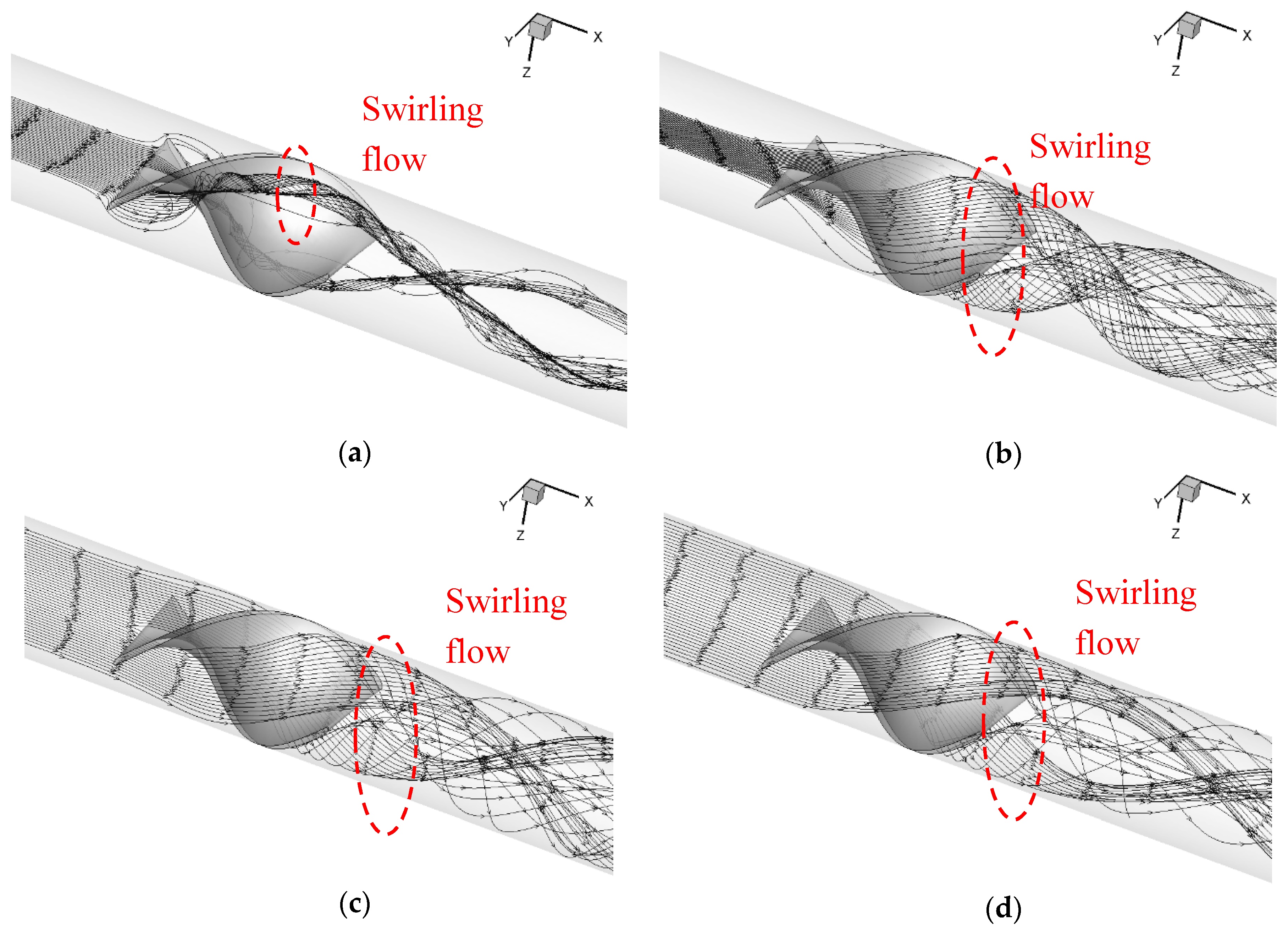
Contour plots of streamlines through the tube with one single element are displayed in Figure 5, which clearly depicts that various turbulence patterns were produced because of the abrupt appearance of the inserted tape, which was quite different from periodic patterns of full-length tapes. Depending on the relative attack angle between the fluid and twisted tape, the turbulence strength and formation region varied. Combining all these flow patterns, a complex flow status was formed, and the temperature distribution seen in Figure 4 could find rationality from this.
4.2. Local Heat Transfer Coefficient
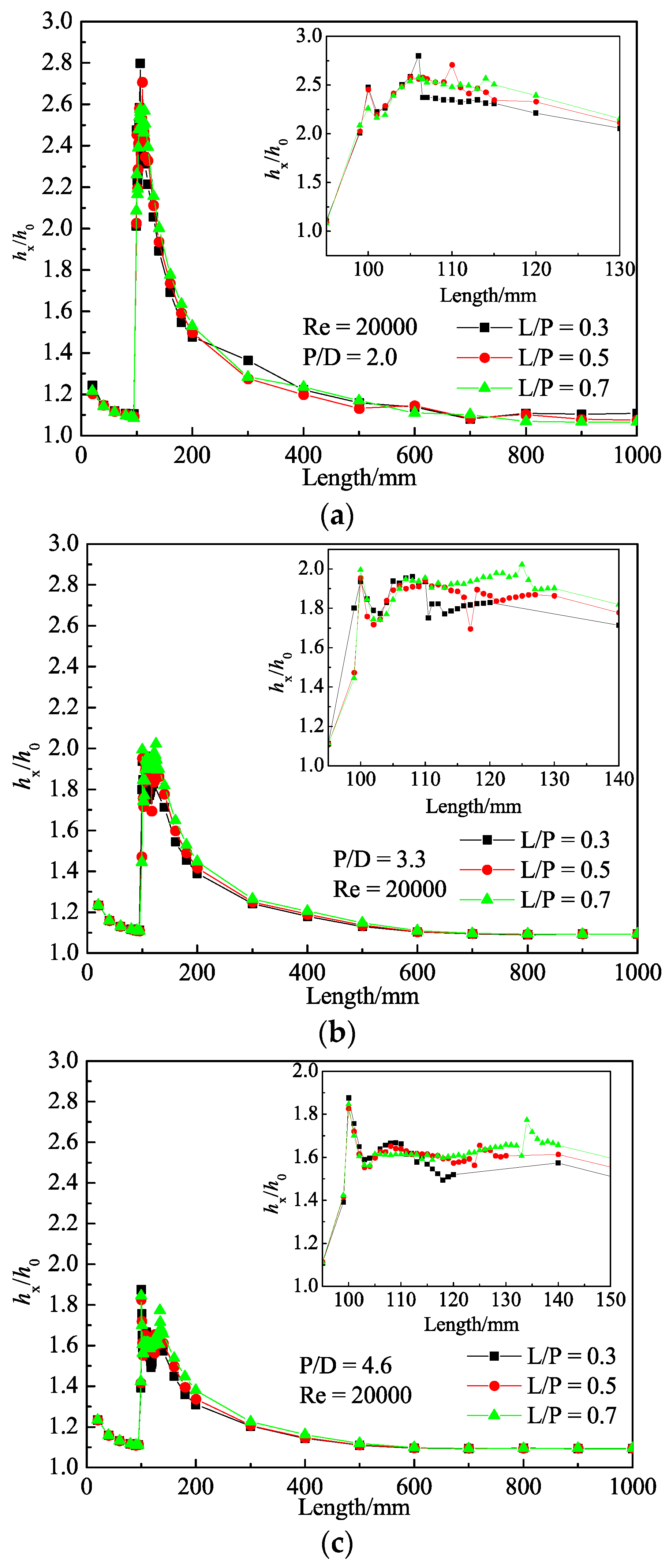
Along the axial direction, local heat transfer rate in terms of hx through the cross-section of the fluid domain was calculated according to Equation (10) and the hx over average value of the plain tube h0 was plotted in Figure 6, Figure 7 and Figure 8.
The difference in various operation conditions (different geometry configurations and Reynolds numbers) was numerically studied, and the results are plotted in Figure 6. Generally, hx/h0 experienced a sharp increase near 100 mm, where the segmented twisted tape is inserted. However, contrary to expectations, the Reynolds number seemed not to have a strong influence on the convective heat transfer coefficient. However, little different was observed in cases with the same P/D and formed three distinctive group at different length ratios. The best performance observed in cases whose P/D equalled 2.0 in every L/P and Re meant that the effect of the twist ratio (P/D) surpassed the effect of the Reynolds number and dominated the overall range. The small discrepancy within a group may be explained by the following: The Reynolds number is calculated according to the condition at the inlet and may deviate from the actual fluid state in the local turbulent region. Thus, the acutely turbulent flow near the vortex generator could not be reflected accurately.
The investigation about the effect of length ratio (L/P) at fixed P/D on the local heat transfer coefficient was carried out and results at Re = 20,000 are depicted in Figure 7, in which a similar trend as in Figure 6 is observed. As shown in the partially enlarged drawings, after peaking at the highest value, hx/h0 reached a plateau and lasted until the end of the tape; then, a gradual decrease was observed. Smaller L/P at fixed P/D was witnessed by the earlier drop in the local heat transfer heat coefficient after the tape region, which could be read from the change of black dotted data points; even they experienced the same trend at first in accordance with the other twos. This difference can be explained by the early stoppage of the fierce turbulence region caused by twisted tape. In the following process, the tubes with longer tape generally had better performance, which meant the longer tape had positive impacts on heat transfer performance.
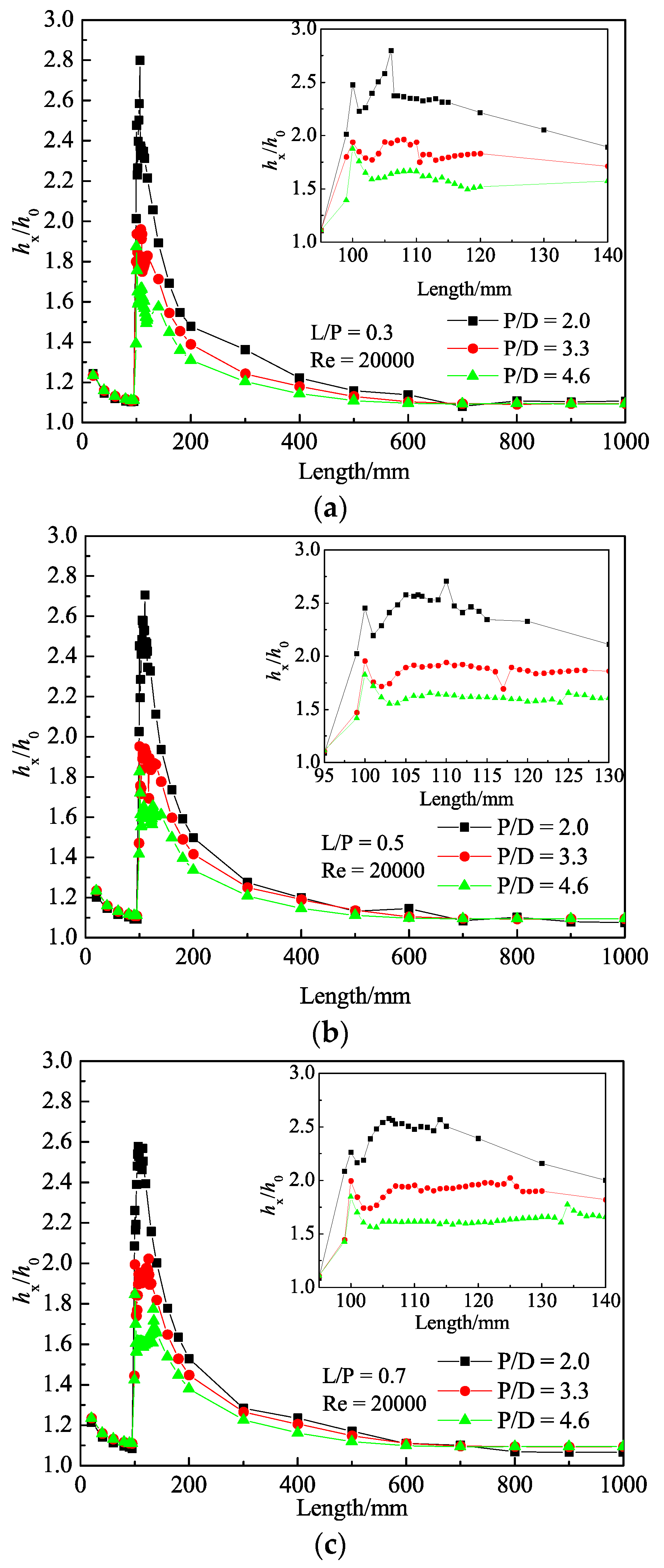
The influence of the length ratio with fixed L/P on heat transfer enhancement is presented in Figure 8. As shown in the pictures, the largest value, 2.8, was observed when P/D equalled 2.0, while the lowest value was only 1.9 at point P/D = 4.6. This local enhancement was better than that in [38], even though only average data was available from that study. The smallest twist ratio (P/D = 2.0) with constant length ratio (L/P) witnessed the best performance, guaranteeing the highest value in the local region and along the rest of the tube. As discussed above, the length ratio had an influence on hx/h0, which caused the largest difference of about 0.2. However, the effect of the twist ratio still surpassed this effect, so it is safe to conclude that the twist ratio played a dominant role in heat transfer enhancement. One reason is that deviation around the hx/h0 was observed within a common range from 100 mm to 110 mm, in which all the different twisted tapes existed. Another is that after the common range, the deviation in all subplots could still be observed with the smallest twist ratio (P/D = 2.0) remaining the largest.
4.3. Overall Heat Transfer Coefficient
The effect of twisted tapes in different twist ratios (P/D) and length ratios (L/P) on the heat transfer, friction factor and performance evaluation factor was studied and is presented in Figure 9, Figure 10 and Figure 11. The outcomes of smooth tubes under the same Reynolds number were compared to the results in single-twisted-tape cases. As illustrated in Figure 9, the dimensionless value of Nu/Nu0 varied from 1.125 to 1.235, indicating the enhancement of segmented twisted tape in heat transfer. Displayed in different colours, three distinct zones in different twist ratios (P/D) were observed, which means that a small twist ratio and large length ratio of inserted tape had positive impacts on the heat transfer enhancement. The quantitative results showed that the highest enhancement of mean heat transfer rate could reach up to 23.5% when P/D = 2.0 and L/P = 0.7. For specific cases with the fixed twist ratio, the longer the twisted tape was, the bigger the Nu number was. This could be attributed to the fact that tape with a small twist ratio generated a strong swirl flow, causing a thinner thermal or hydrodynamic boundary layer and promoting heat exchange with the tube wall. Besides, the long smooth surface of twisted tapes contributed to the growth of swirl flow; thus, energy could be transferred fast and effectively across the boundary layer.
The frictional characteristic of twisted tapes is depicted in Figure 10. Results show that the variance of friction factor f became larger at specific Reynolds numbers when P/D decreased, while a constant gap under different Reynolds numbers could be observed in the region highlighted in the same colour. The upward tendency was different from results given in other relevant works [20,31,38], but as P/D increased, the upward trend was weakened. This phenomenon may be attributed to the unique geometry features of the research interest.
The performance evaluation factor of tubes with different twisted tapes obtained by computational simulation is given in Figure 11, which shows the cost of saved energy. The best performance was obtained in tubes with tapes having twist ratio P/D = 4.6 at small Reynolds numbers, with η reaching slightly over 1, while the lowest value of η at 0.887 was observed when P/D = 2.0 when Re = 35,000. It can be implied that low Reynolds number was friendlier to this design. This means that due to the increase of Reynolds number, the friction factor f gradually became larger and began to dominate over the gain of heat transfer enhancement.
5. Conclusions
The thermal performance enhancement and consequential cost of segmented twisted tape with different geometric features are numerically studied and the effect of twist ratio (P/D) and length ratio (L/P) under different operation conditions are discussed. A realisable k-ε turbulence model with enhanced wall function is employed in the simulation. The predicted temperature distribution is displayed in contour plots, and the streamline through the tube is provided as reference. The important conclusions of this study can be summarised as follows:
- (1)
- Segmented twisted tapes can disturb the growth of developed flow and generate a vortex, thus increasing local heat transfer coefficient hx/h0 up to 2.8.
- (2)
- Twist ratio P/D plays a more critical role in local heat transfer enhancement over length ratio L/P, and a smaller P/D usually has a better performance.
- (3)
- Twisted tapes with P/D = 2.0 and L/P = 0.3 yield the highest heat transfer rate and performance evaluation factor.
- (4)
- In comparison with the smooth tube, the largest enhancement of heat transfer performance in terms of Nu can reach up to 23.5%, but along with a more than doubled friction factor at 2.35.
- (5)
- It seems that a bigger pressure loss is the cost when achieving entirely better heat transfer performance for segmented twisted tape inserts.
Author Contributions
G.L. and J.Z. conceived and designed the model; C.Y. and H.Z. helped in the simulation and analysed the data; G.L. wrote the paper; J.Z., B.X. and J.-y.Q. revised the paper. All authors have read and agreed to the published version of the manuscript.
Funding
The work was funded by the National Natural Science Foundation of China (under Grant No. 51605425) and National Key R&D Program of China (under Grant No. 2018YFB2000704).
Conflicts of Interest
The authors declare no conflict of interest.
Abbreviations
Nomenclature
| Ax | cross section area of fluid at location x, m2 |
| Cμ | turbulence model constant |
| D | inner tube diameter, mm |
| E | total energy, J |
| f | friction factor |
| h | convective heat transfer coefficient, W m−2 K−1 |
| hx | local convective heat transfer coefficient at the length of x mm, W m−2 K−1 |
| k | turbulent kinetic energy |
| L | tape length, mm |
| Nu | Nusselt number |
| Nu0 | Nusselt number in plain tube |
| P | pitch of twisted tape, mm |
| p | static pressure, Pa |
| Q | total heat transfer, W |
| qm | mass flow, kg·s−1 |
| Re | Reynolds number |
| S | tube length |
| T | temperature, K |
| Tw | wall temperature |
| average temperature of fluid, K | |
| u | mean velocity, m s−1 |
| ui | velocity components, m s−1 |
| fluctuation velocity components, m s−1 |
Greek symbols
| δij | Kronecker delta |
| ε | turbulent dissipation rate, m2 s−3 |
| λ | thermal conductivity, W m−1 K−1 |
| λeff | effective thermal conductivity, W m−1 K−1 |
| μ | kinematic viscosity, kg s−1 m−1 |
| μt | eddy viscosity, kg s−1 m−1 |
| η | performance evaluation factor |
| ρ | density, kg m−3 |
References
- Kumar, P.; Judd, R.L. Heat transfer with coiled wire turbulence promoters. Can. J. Chem. Eng. 1970, 48, 378–383. [Google Scholar] [CrossRef]
- Pak, B.C.; Cho, Y.I. Hydrodynamic and heat transfer study of dispersed fluids with submicron metallic oxide particles. Exp. Heat Transf. 1998, 11, 151–170. [Google Scholar] [CrossRef]
- Xuan, Y.; Li, Q. Heat transfer enhancement of nanofluids. Int. J. Heat Fluid Flow 2000, 21, 58–64. [Google Scholar] [CrossRef]
- Pavel, B.I.; Mohamad, A.A. An experimental and numerical study on heat transfer enhancement for gas heat exchangers fitted with porous media. Int. J. Heat Mass Transf. 2004, 47, 4939–4952. [Google Scholar] [CrossRef]
- Qian, J.-Y.; Li, X.-J.; Wu, Z.; Jin, Z.-J.; Sunden, B. A comprehensive review on liquid–liquid two-phase flow in microchannel: Flow pattern and mass transfer. Microfluid. Nanofluid. 2019, 23, 207. [Google Scholar] [CrossRef]
- Qian, J.-y.; Wu, Z. Heat transfer analysis on dimple geometries and arrangements in dimple jacketed heat exchanger. Int. J. Numer. Methods Heat Fluid Flow 2019, 29, 2775–2791. [Google Scholar] [CrossRef]
- Xue, Y.; Ge, Z.; Du, X.; Yang, L. On the Heat Transfer Enhancement of Plate Fin Heat Exchanger. Energies 2018, 11, 1398. [Google Scholar] [CrossRef] [Green Version]
- Bayram, H.; Sevilgen, G. Numerical Investigation of the Effect of Variable Baffle Spacing on the Thermal Performance of a Shell and Tube Heat Exchanger. Energies 2017, 10, 1156. [Google Scholar] [CrossRef] [Green Version]
- ERG. Duocel Aluminum Foam Data Sheet. In ERG Material and Aerospace; ERG: Oakland, CA, USA, 1999. [Google Scholar]
- Webb, R.L. Enhancement of single-phase heat transfer. In Handbook of Single-Phase Convective Heat Transfer; John Wiley & Sons, Inc.: New York, NY, USA, 1987. [Google Scholar]
- Kays, W.M.; London, A.L.; Eckert, E.R.G. Compact heat exchangers. ASME J. Appl. Mech. 1960, 27, 377. [Google Scholar] [CrossRef] [Green Version]
- Boomsma, K.; Poulikakos, D.; Zwick, F. Metal foams as compact high performance heat exchangers. Mech. Mater. 2003, 35, 1161–1176. [Google Scholar] [CrossRef]
- Lacroix, M.; Nguyen, P.; Schweich, D.; Pham Huu, C.; Savin-Poncet, S.; Edouard, D. Pressure drop measurements and modeling on SiC foams. Chem. Eng. Sci. 2007, 62, 3259–3267. [Google Scholar] [CrossRef]
- Busse, C.; Freund, H.; Schwieger, W. Intensification of heat transfer in catalytic reactors by additively manufactured periodic open cellular structures (POCS). Chem. Eng. Process. Process Intensif. 2018, 124, 199–214. [Google Scholar] [CrossRef]
- Chaudhari, A.; Ekade, P.; Krishnan, S. Experimental investigation of heat transfer and fluid flow in octet-truss lattice geometry. Int. J. Therm. Sci. 2019, 143, 64–75. [Google Scholar] [CrossRef]
- Fan, J.F.; Ding, W.K.; Zhang, J.F.; He, Y.L.; Tao, W.Q. A performance evaluation plot of enhanced heat transfer techniques oriented for energy-saving. Int. J. Heat Mass Transf. 2009, 52, 33–44. [Google Scholar] [CrossRef]
- Ji, W.-T.; Jacobi, A.M.; He, Y.-L.; Tao, W.-Q. Summary and evaluation on single-phase heat transfer enhancement techniques of liquid laminar and turbulent pipe flow. Int. J. Heat Mass Transf. 2015, 88, 735–754. [Google Scholar] [CrossRef]
- Bergles, A.E.; Morton, H.L. Survey and Evaluation of Techniques to Augment Convexction Heat Exchanger; MIT Dept. of Mechanical Engineering: Cambridge, MA, USA, 1965. [Google Scholar]
- Wijayanta, A.T.; Aziz, M.; Kariya, K.; Miyara, A. Numerical Study of Heat Transfer Enhancement of Internal Flow Using Double-Sided Delta-Winglet Tape Insert. Energies 2018, 11, 3170. [Google Scholar] [CrossRef] [Green Version]
- Wijayanta, A.; Pranowo; Mirmanto; Kristiawan, B.; Aziz, M. Internal Flow in an Enhanced Tube Having Square-cut Twisted Tape Insert. Energies 2019, 12, 306. [Google Scholar] [CrossRef] [Green Version]
- Chang, S.W.; Jan, Y.J.; Liou, J.S. Turbulent heat transfer and pressure drop in tube fitted with serrated twisted tape. Int. J. Therm. Sci. 2007, 46, 506–518. [Google Scholar] [CrossRef]
- Chang, S.W.; Yu, K.-W.; Lu, M.H. Heat Transfers in Tubes Fitted with Single, Twin, and Triple Twisted Tapes. Exp. Heat Transf. 2005, 18, 279–294. [Google Scholar] [CrossRef]
- Wongcharee, K.; Eiamsa-ard, S. Heat transfer enhancement by twisted tapes with alternate-axes and triangular, rectangular and trapezoidal wings. Chem. Eng. Process. Process Intensif. 2011, 50, 211–219. [Google Scholar] [CrossRef]
- Thianpong, C.; Eiamsa-ard, P.; Promvonge, P.; Eiamsa-ard, S. Effect of perforated twisted-tapes with parallel wings on heat transfer enhancement in a heat exchanger tube. Energy Procedia 2012, 14, 1117–1123. [Google Scholar] [CrossRef] [Green Version]
- Hasanpour, A.; Farhadi, M.; Sedighi, K. Intensification of heat exchangers performance by modified and optimized twisted tapes. Chem. Eng. Process. Process Intensif. 2017, 120, 276–285. [Google Scholar] [CrossRef]
- Manglik, R.M.; Bergles, A.E. Heat Transfer and Pressure Drop Correlations for Twisted-Tape Inserts in Isothermal Tubes_Part II—Transition and Turbulent Flows. J. Heat Transf. 1993, 115, 890–896. [Google Scholar] [CrossRef]
- Hong, S.W.; Bergles, A.E. Augmentation of Laminar Flow Heat Transfer in Tubes by Means of Twisted-Tape Inserts. J. Heat Transf. 1976, 98, 251–256. [Google Scholar] [CrossRef]
- Saha, S.K.; Gaitonde, U.N.; Date, A.W. Heat transfer and pressure drop characteristics of laminar flow in a circular tube fitted with regularly spaced twisted-tape elements. Exp. Therm. Fluid Sci. 1989, 2, 310–322. [Google Scholar] [CrossRef]
- Eiamsa-ard, S.; Thianpong, C.; Promvonge, P. Experimental investigation of heat transfer and flow friction in a circular tube fitted with regularly spaced twisted tape elements. Int. Commun. Heat Mass Transf. 2006, 33, 1225–1233. [Google Scholar] [CrossRef]
- Zimparov, V. Enhancement of heat transfer by a combination of threestart spirally corrugated tubes with a twisted tape. Heat Mass Transf. 2001, 44, 551–574. [Google Scholar] [CrossRef]
- AI-Fahed, S.; Chakroun, W. Effect of tube-tape clearance on heat transfer for fully developed turbulent flow in a horizontal isothermal tube. Int. J. Heat Fluid Flow 1996, 17, 173–178. [Google Scholar] [CrossRef]
- Hansjosten, E.; Wenka, A.; Hensel, A.; Benzinger, W.; Klumpp, M.; Dittmeyer, R. Custom-designed 3D-printed metallic fluid guiding elements for enhanced heat transfer at low pressure drop. Chem. Eng. Process. Process Intensif. 2018, 130, 119–126. [Google Scholar] [CrossRef]
- Femmer, T.; Kuehne, A.J.C.; Wessling, M. Estimation of the structure dependent performance of 3-D rapid prototyped membranes. Chem. Eng. J. 2015, 273, 438–445. [Google Scholar] [CrossRef]
- Martinez, L.I. Investigation of CFD Conjugate Heat Transfer Simulation Methods for Engine Components at SCANIA CV AB. 2017. Available online: http://urn.kb.se/resolve?urn=urn:nbn:se:liu:diva-138758 (accessed on 31 December 2019).
- Balafas, G. Polyhedral Mesh Generation for CFD-Analysis of Complex Structures. Master’s Thesis, Technische Universität München, München, Germany, 2014. [Google Scholar]
- Peric, M.; Ferguson, S. The Advantage of Polyhedral Meshes. Available online: http://www.cd-adapco.com/press_room/-dynamics/24/testVspoly.html (accessed on 21 October 2019).
- Ghadirijafarbeigloo, S.; Zamzamian, A.H.; Yaghoubi, M. 3-D Numerical simulation of heat transfer and turbulent flow in a receiver tube of solar parabolic trough concentrator with louvered twisted-tape inserts. Energy Procedia 2014, 49, 373–380. [Google Scholar] [CrossRef] [Green Version]
- Eiamsa-ard, S.; Wongcharee, K.; Sripattanapipat, S. 3-D Numerical simulation of swirling flow and convective heat transfer in a circular tube induced by means of loose-fit twisted tapes. Int. Commun. Heat Mass Transf. 2009, 36, 947–955. [Google Scholar] [CrossRef]
- He, C.H.; Feng, X. Principles of Chemical Engineering; Science Press: Beijing, China, 2007. [Google Scholar]
- Yang, C.; Chen, M.-R.; Qian, J.-Y.; Wu, Z.; Jin, Z.-J.; Sunden, B. Heat transfer study of a hybrid smooth and spirally corrugated tube. Heat Transf. Eng. 2019, 1–13. [Google Scholar] [CrossRef] [Green Version]
Figure 1.
Schematic of (a) evenly distributed twisted tape and (b) research of interest.

Figure 2.
Boundary mesh at the inlet and inserted tape surface using polyhedra.

Figure 3.
Comparison of Nu and f between empirical equations and simulation results.

Figure 4.
Temperature field comparison between the research object and the smooth tube at different locations. Tube with tape: (a) x = 108 mm, (b) x = 118 mm, (c) x = 138 mm, (d) x = 168 mm, (e) x = 218 mm, (f) x = 418 mm. Smooth tube: (g) x = 108 mm, (h) x = 168 mm, (i) x = 218 mm, (j) x = 418 mm.
Figure 4.
Temperature field comparison between the research object and the smooth tube at different locations. Tube with tape: (a) x = 108 mm, (b) x = 118 mm, (c) x = 138 mm, (d) x = 168 mm, (e) x = 218 mm, (f) x = 418 mm. Smooth tube: (g) x = 108 mm, (h) x = 168 mm, (i) x = 218 mm, (j) x = 418 mm.

Figure 5.
Contour plot of streamline at different attack angles (x-direction, counter clockwise): (a) 0°, (b) 45°, (c) 90°, (d) 135°.
Figure 5.
Contour plot of streamline at different attack angles (x-direction, counter clockwise): (a) 0°, (b) 45°, (c) 90°, (d) 135°.

Figure 6.
Local convective heat transfer coefficient along the tube: (a) L/P = 0.3, (b) L/P = 0.5, (c) L/P = 0.7.
Figure 6.
Local convective heat transfer coefficient along the tube: (a) L/P = 0.3, (b) L/P = 0.5, (c) L/P = 0.7.

Figure 7.
Relationship between heat transfer coefficient and length ratio along the tube: (a) P/D = 2.0, (b) P/D = 3.3, (c) P/D = 4.6.
Figure 7.
Relationship between heat transfer coefficient and length ratio along the tube: (a) P/D = 2.0, (b) P/D = 3.3, (c) P/D = 4.6.

Figure 8.
Relationship between heat transfer coefficient and twist ratio along the tube: (a) L/P = 0.3, (b) L/P = 0.5, (c) L/P = 0.7.
Figure 8.
Relationship between heat transfer coefficient and twist ratio along the tube: (a) L/P = 0.3, (b) L/P = 0.5, (c) L/P = 0.7.

Figure 9.
Relationship between Nu and Reynolds number.

Figure 10.
Relationship between f and Reynolds number.

Figure 11.
Relationship between η and Reynolds number.

© 2020 by the authors. Licensee MDPI, Basel, Switzerland. This article is an open access article distributed under the terms and conditions of the Creative Commons Attribution (CC BY) license (http://creativecommons.org/licenses/by/4.0/).
Share and Cite
MDPI and ACS Style
Liu, G.; Yang, C.; Zhang, J.; Zong, H.; Xu, B.; Qian, J.-y. Internal Flow Analysis of a Heat Transfer Enhanced Tube with a Segmented Twisted Tape Insert. Energies 2020, 13, 207. https://doi.org/10.3390/en13010207
AMA Style
Liu G, Yang C, Zhang J, Zong H, Xu B, Qian J-y. Internal Flow Analysis of a Heat Transfer Enhanced Tube with a Segmented Twisted Tape Insert. Energies. 2020; 13(1):207. https://doi.org/10.3390/en13010207
Chicago/Turabian StyleLiu, Gan, Chen Yang, Junhui Zhang, Huaizhi Zong, Bing Xu, and Jin-yuan Qian. 2020. "Internal Flow Analysis of a Heat Transfer Enhanced Tube with a Segmented Twisted Tape Insert" Energies 13, no. 1: 207. https://doi.org/10.3390/en13010207
Note that from the first issue of 2016, this journal uses article numbers instead of page numbers. See further details here.