Optimal Phase Arrangement of Distribution Transformers for System Unbalance Improvement and Loss Reduction

1
College of Intelligence Robot, Fuzhou Polytechnic, Fuzhou 350108, China
2
Department of Electrical Engineering, Cheng-Shiu University, Kaohsiung 833, Taiwan
*
Author to whom correspondence should be addressed.
Energies 2020, 13(3), 545; https://doi.org/10.3390/en13030545
Submission received: 25 December 2019
/
Revised: 17 January 2020
/
Accepted: 20 January 2020
/
Published: 22 January 2020
Abstract
:This paper presents an efficient strategy for transformer planning to reduce the system losses by means of transformer rearrangement. The customer connected to the distribution transformer are first investigated by the field survey, and the loads of the various customers are collected from the customer information system (CIS) and distribution database system (DAS) to derive their load patterns. The objective function is to minimize the total line loss in the 24 intervals. An improved bacterial foraging algorithm (IBFO) is proposed herein to find the optimal phase combination of distribution transformers to minimize the total line loss by considering operating constraints. A three-phase load flow program with Eeuivalent current injection (ECT) is used to solve the total line loss and system unbalance factor on a Taipower distribution system. The results can help operators not only perform the proper installation phase selection of distribution transformers, but also reduce the system losses, decrease the system unbalance factor, and improve the voltage profiles of the buses.
1. Introduction
In Taiwan, the Taiwan Power Company (Taipower) usually uses two single-phase transformers to connect to an Open-Wye/Open Delta transformer for serving both the single-phase and three-phase loads, and it is more economical for transformer management [1]. In Taipower distribution system, there exist a number of Open-Wye/Open-Delta transformers for the sake of economic and future expansion considerations [2,3]. A distribution feeder inherently produces the three-phase unbalance due to the lack of a third transformer and the two kinds of load served. This causes the phase voltage and current along a distribution feeder to become unbalanced. The unbalanced situations will lead to extra line losses, communication obstruction, and shorter service life of equipment [4,5]. A serious issue is that the grounding relay will trip due to the phase unbalance. The power quality and operation efficiency in the distribution system will also be reduced.
In general, the capacity selection of a distribution transformer is mostly based on the peak of the load. An Open-Wye/Open Delta transformer or three-phase transformer may simultaneously serve both the single-phase loads and three-phase loads. The loads changed in the three phases try to balance the current of three phases by using a transformer connected rearrangement. The process of transformer rearrangement ensures distribution loads on three phases to balance the current flow in the distribution system. It makes the neutral current the lowest, thereby having minimal line loss in the distribution feeder. Due to Open-Wye/Open Delta transformer’s reconnection on the secondary side is not easily implemental, and field operators may not know how the changes will reflect on the prime side. This research tried to resolve the problem by load re-assignment through prime phase re-sequencing. Both the system balance and line loss problems were considered in this paper.
In the past, there is not much research literature on transformer rearrangement. Genetic algorithm (GA) was used to optimize the phase arrangement of distribution transformers connected for improving the system unbalance and loss reduction [6]. By considering the voltage-dependency of loads, particle swarm optimization (PSO) is applied for the phase-balancing of distribution feeder [7]. An NSGA-II application for phase balancing of primary distribution circuits by the reconnection of circuit laterals and distribution transformers was implemented to minimize both line losses and unbalance factor [8]. An expert system is proposed to take the rephase strategy of distribution transformers to improve the three-phase balancing of the distribution system [9]. Bird-mating is adopted to assist in the coordinated switching of phase connection in Open-Wye/Open Delta transformers to achieve better voltage balance [10]. An automatic phase load balancing methodology is proposed herein which can balance the load on three phases of the distribution transformers [11]. Linear programming and dynamic programming were integrated to find the optimal phase arrangement of a distribution transformer for a feeder [12,13]. A three-phase load flow program is used to calculate the line losses in cases of transformer rearrangement, optimal load diversity, and mixed-type.
The problem for the phase arrangement of a distribution transformer can be formulated as a non-linear mixed-integer combinatorial optimization problem, which can be obtained by a complete enumeration of all feasible combinations. It involves high complexity in the search space, which manifests itself in the form of complicated constraints imposed on variables and the probable large number of variables in the searching process. To determine the best operating system, an efficient tool is needed to solve this problem. The purpose of this paper is to propose an improved bacterial foraging algorithm (IBFO) as a new approach in solving the optimal phase arrangement of the distribution transformers problem. Bacterial foraging optimization (BFO) is a nature-inspired optimization algorithm, which introduces the foraging behavior of bacteria based on competitive–cooperative mechanism [14]. In the past, BFO was successfully applied to various fields of power system optimization [15,16,17,18,19]. Improved BFO has also been successfully applied to optimize some problems in engineering and scientific fields [20,21,22,23,24]. The integration of gradient particles swarm (GPSO) and BFO was proposed to solve the optimization of distributed generation [20]. The standard benchmark problems with a large number of local optimal solutions are used for examples and solved by Chaotic BFO [21] and effective BFO [22]. Particle swarm optimization and BFO were integrated to solve the optimal schedule strategy for the active distribution network problem [23]. A GA-BFO algorithm was proposed to improve the security of the heterogeneous network routing protocols [24]. By combining BFO and stochastic weight trade-off (SWT) [25], this paper proposed another version of IBFO in order to refine the solution quality. For the first time, the proposed IBFO is applied to the phase arrangement of distribution transformers. A three-phase load flow program with the equivalent current injection (ECI) [26] is used to analyze the effect of the IBFO on a practical distribution feeder. Simulation results can help operators to improve the system unbalance and voltage profile, as well as enhance the operating efficiency of the distribution system.
2. The Problem Description
2.1. Transformer Connection Types
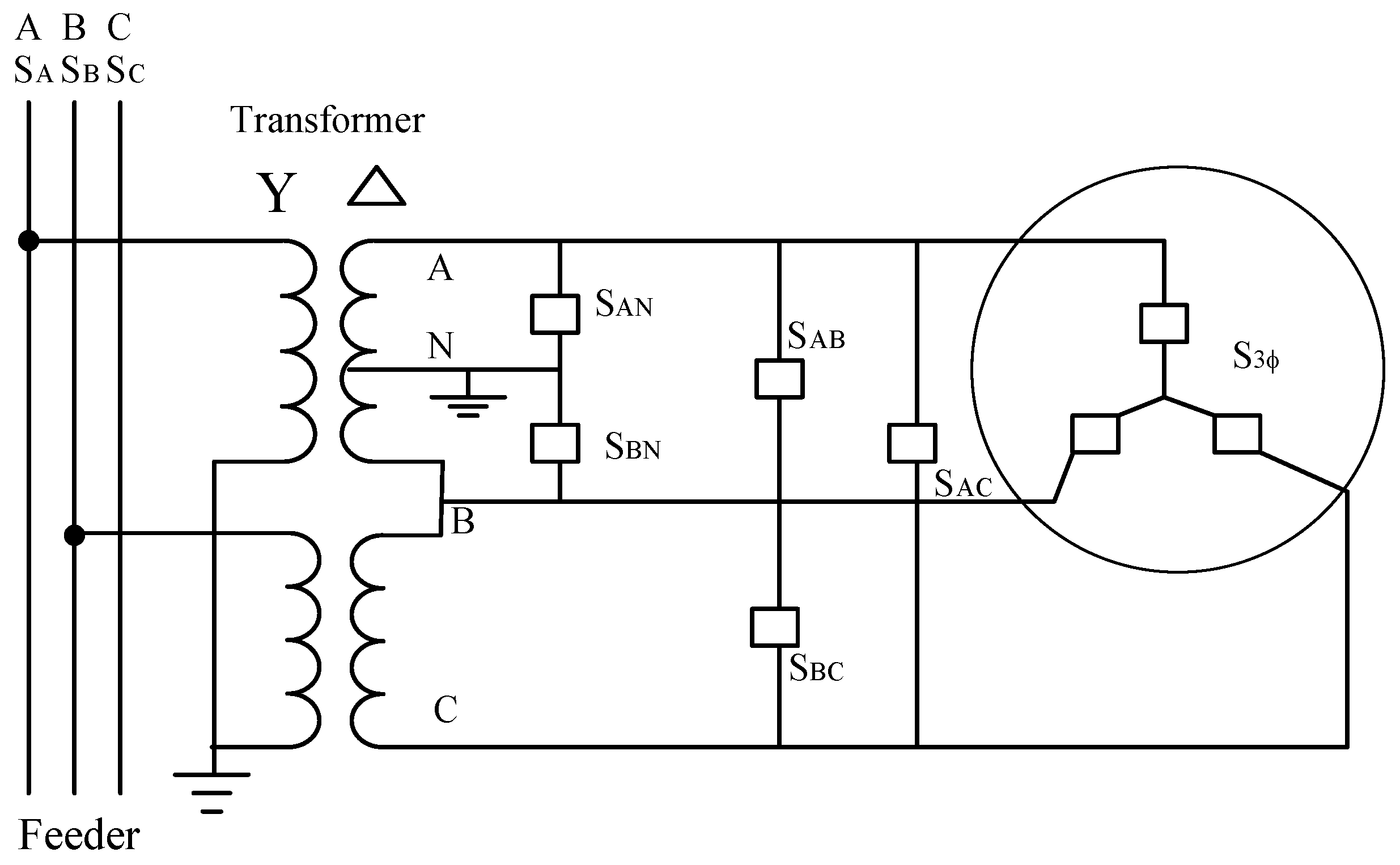
Figure 1 shows loads of the Open-Wye/Open Delta transformers meant to serve both the single-phase and three-phase loads. The loads at the secondary lateral consist of the single-phase and three-phase loads, which are equivalently represented by two individual phases () at the primary lateral. The load at each phase is expressed as Equations (1)–(3). As it does not matter what type of transformer needs to be connected to the feeder, many schemes can be selected to connect to the phases A–C of the primary lateral in the various connected arrangements. The possible connection schemes for the various types of each transformer are listed in Table 1.
In Table 1, the arrangement of the equivalent loads in the primary lateral has 6 connection types, 3 connection types, and 3 connection types for the transformers, Open-Wye/Open Delta transformer, and single-phase transformer. The main purpose of this paper is to find the optimal scheme for the transformer connection to minimize the real power line losses and improve the voltage unbalance factor.
2.2. Transformer Equivalent Load
In the Taipower distribution system, the record of each customer in the Customer Information System (CIS) must be connected to a transformer secondary side in the Distribution Database System (DAS). The power consumption of each customer is recorded in the CIS. Since a distribution transformer may simultaneously serve the mixed loading of various customers, the transformer loads can be estimated based on each customer type. By using CIS and DAS, the phase hourly loads in the primary side can be derived based on the connection of the transformer, the loads on the secondary side, and their corresponding load patterns. In this paper, the phase hourly load of each distribution transformer is calculated by the field survey and typical load patterns. The percentage of hourly energy consumption over one day is calculated by Equation (4) and the hourly real power consumption of each load customer is solved by Equation (5). Therefore the transformer loading can be easily obtained by summing the hourly loading of each customer served by the transformer as expressed in Equation (6). By considering the load growth of customers:
2.3. The Objective Function for Phase Rearrangement of Transformers
The objective function for phase rearrangement of transformers is to minimize the total line loss during the 24 intervals. The loss-minimizing problem can be formulated as:
The objective function of is defined as follows:
The voltage and current constraints are considered in Equations (9)–(11). Any combination which violates the following constraints is no longer selected:
The fitness function is defined as:
where is the objective function, is the inequality constraints such as Equations (9)–(11); is the state value of i-th bacterium; is the number of inequality constraints; is the penalty factor that can be adjusted in the optimization procedure; and is defined by:
In accordance with IEEE ANSI standard, the voltage unbalance factor of the i-th bus is defined as Equation (14):
3. Solution Algorithm
BFO was developed by [14] for numerical optimization in 2005; this search algorithm is based on the mechanism of bacterial foraging behavior. BFO is similar to random search methods, but does not contain complicated mechanisms such as crossover or mutation. BFO generates a set of initial solutions, known as E. coli, and then searches for the optimal value through iteration evolution. More importantly, every bacterium has a memory capacity, and can provide a one-way message to the population. Thus, the search process of BFO is the process of following the current optimal solution. For example, if the bacterium meets a good environment, it will continue to swim in the same direction. Otherwise, it will use the tumble method to seek another direction. Bacteria must constantly move in the process of evolution and gradually tend to move to a better environment for a better solution. This paper proposes IBFO, which integrated the Stochastic Weight Trade-off (SWT) in BFO to improve the local searching ability of individuals. The concept of IBFO is to preserve the balance between global exploration and local exploitation by trading off stochastic weight with using dynamic acceleration coefficients trade-off. The mechanism increased the diversity of bacterial chemotaxis to avoid premature convergence. IBFO was developed as follows.
3.1. Bacterial Chemotaxis
Traditional bacterial chemotaxis is described as Equation (15).
In the process of bacterial chemotaxis, it simply relies on the moving distance () and the tumble direction (); the useful chemotaxis messages are not transmitted between the bacteria. This could lead to a local minimum. Thus, Equation (15) is modified by Equation (17):
where : Random number between 0 and 1 and is a freak factor, which is defined as:
where : The probability of “lethargy”, is the distance factor, which is varied with the stage of the optimization process [27]:
where is a control parameter used to reduce the stochastic effect linearly, also varies with the stage of optimization process:
The bacterial chemotaxis in Equation (17) is controlled by a factor of . This term is referred to as the “stochastic trade-off control factor.” Using the linearly decreasing method would take longer global exploration than the nonlinearly decreasing method, and reduce the individual’s risk of missing the promising area. The values of maximum iterations and are set to 0.5, 2.5, and 0.5, respectively.
3.2. Bacterial Reproduction
After a period of bacterial chemotaxis, there is an obvious difference in the fitness value of the bacterium. For the reproduction process, the bacteria are sorted in order of ascending fitness value and the healthiest bacteria is split into two bacterium, which are placed at the same location. A bacterium with a better fitness value replicates a bacterium identical to itself. In this paper, the reproduction process is set at 20% bacterial replication after 20 times of the chemotaxis process. The formulation of bacterial reproduction is described as follows:
3.3. Elimination-Dispersal
The elimination-dispersal of the bacteria in the population is set on the number of chemotaxis (). A set,, is randomly generated after the chemotaxis. If the generated random variable () is less than the elimination-dispersal rate (), the state value of the bacterium is eliminated, and a new bacterium is generated by Equation (22).
The phase rearrangement of distribution transformers is expressed in discrete state, so the initial solution is obtained by assigning an integer value for the operating status of each bacterium. The feasibility status is assured by the following equations:
where is the n-th connected status of distribution transformers corresponding to the j-th bus. The bacterial chemotaxis is re-defined as in Equation (24):
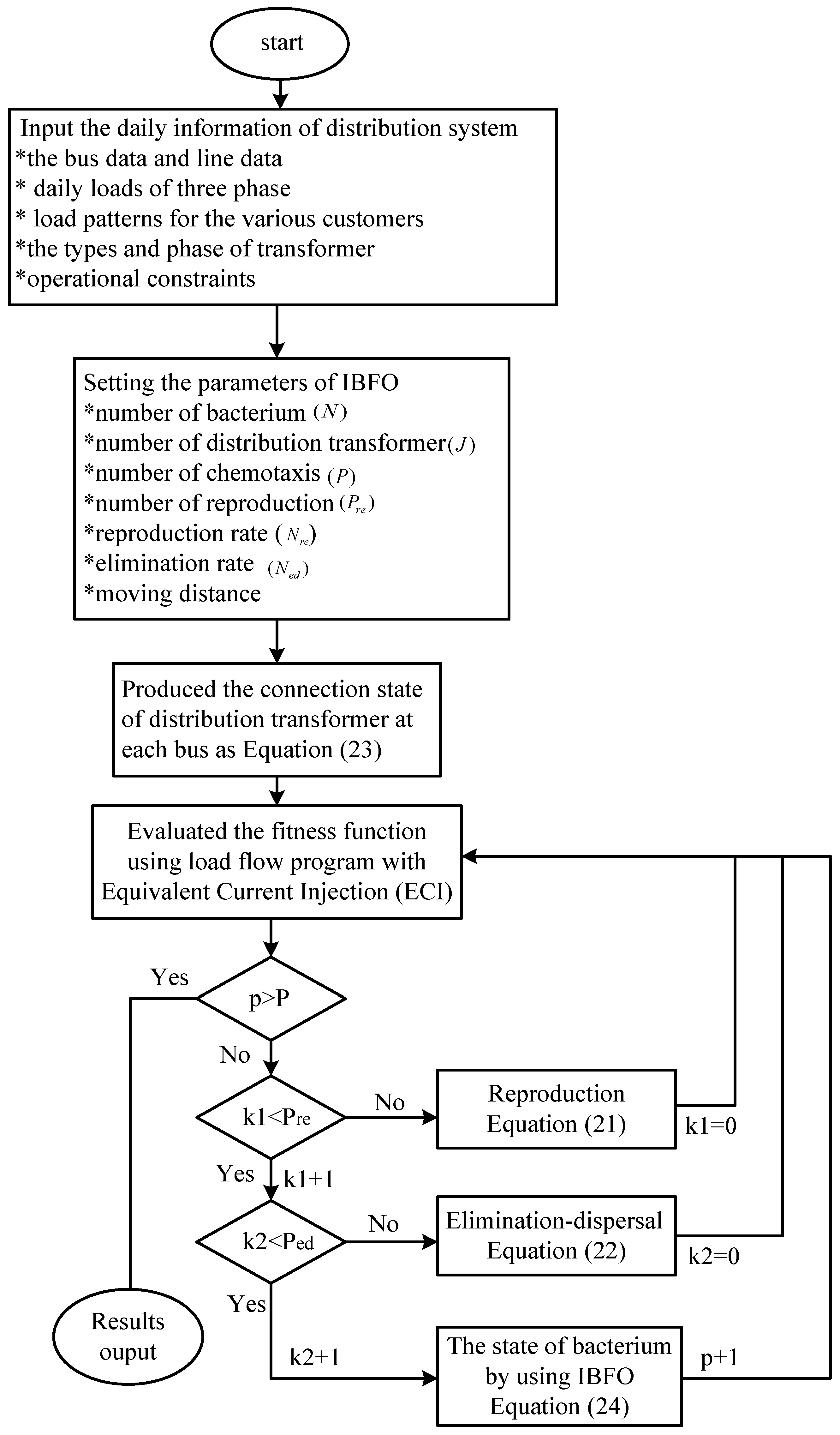
Figure 2 is the flowchart of IBFO applied.
4. Case Study
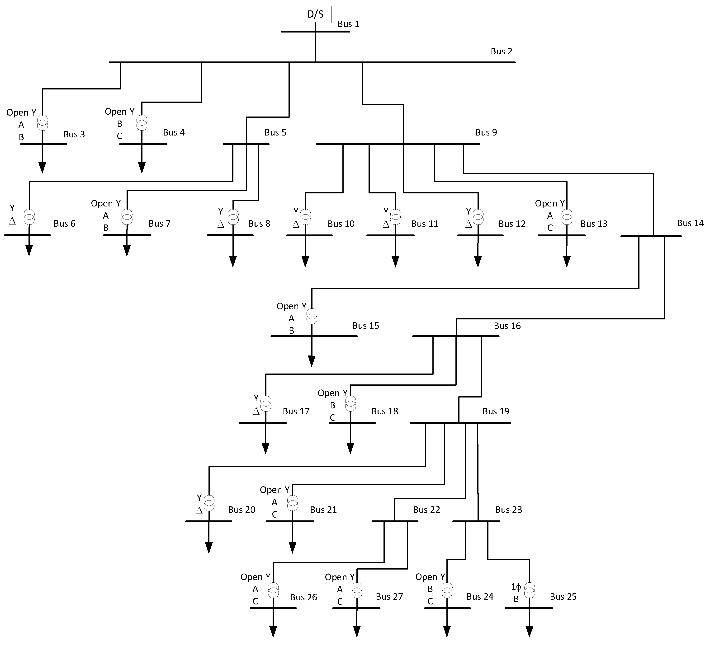
To demonstrate the effectiveness of the IBFO, a practical feeder with 27 buses was selected for analyzing the efficiency, as shown in Figure 3. The load, which is served by this feeder, includes residential, commercial, and several small-industrial customers. There were about 2952 different customers planning to be connected with this feeder. The total capacity of connected transformers was 8600 KVA and a summary of these transformers is listed in Table 2.
4.1. Voltage Profile Improvement
Table 3 is the optimal phase connection of distribution transformers after the IBFO. The load phase of the transformer connections of busses 3, 6, 7, 12, 18, 25, 26 do not need to be changed, while the busses 13, 15, 20, 27 need to change the load phase of the transformer once, and busses 4, 8, 10, 11, 17, 21, 24 require changing twice, while only bus 17 needs to change the load phase three times.
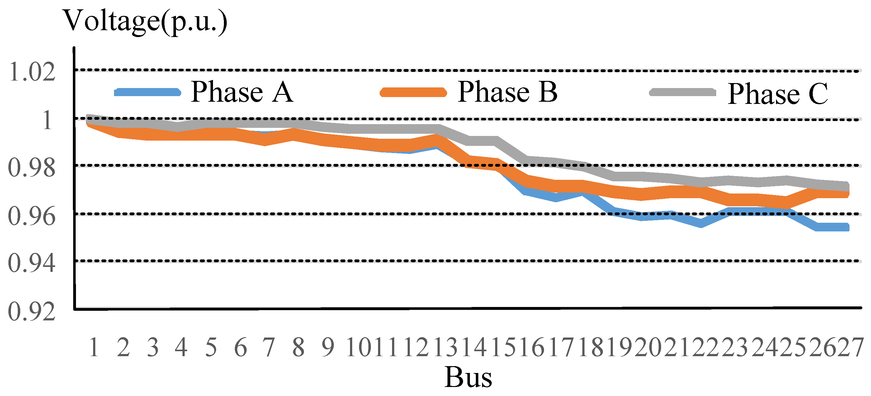
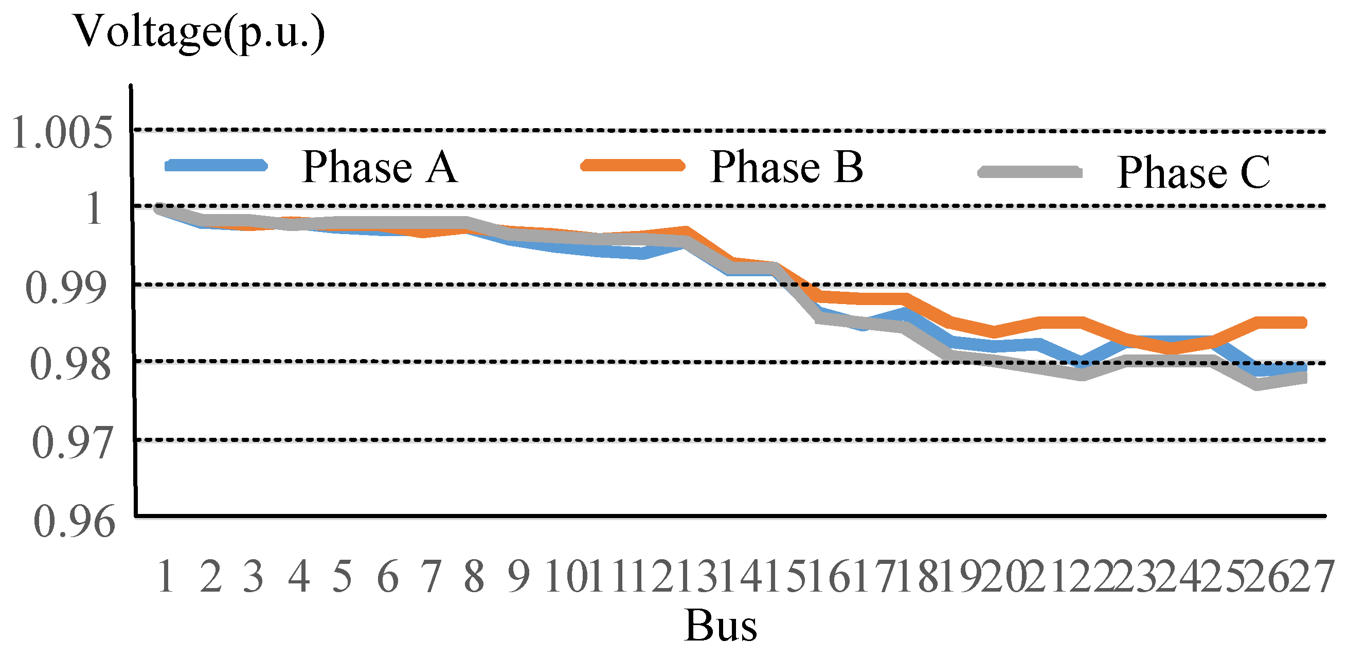
Figure 4 and Figure 5 show the three-phase voltage profiles of each bus before and after phase rearrangement at the light load period (6 am), respectively. In the Figure 4 and Figure 5, the minimum voltage of each bus is operated from 0.958 p.u. to 0.976 p.u. before the phase rearrangement and from 0.972 p.u. to 0.985 p.u. after the phase rearrangement, respectively. It is obvious that the voltage profiles can be improved after the phase rearrangement.
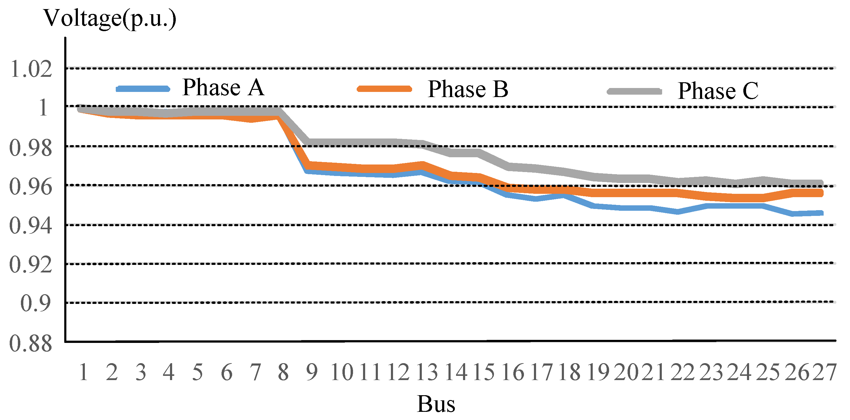
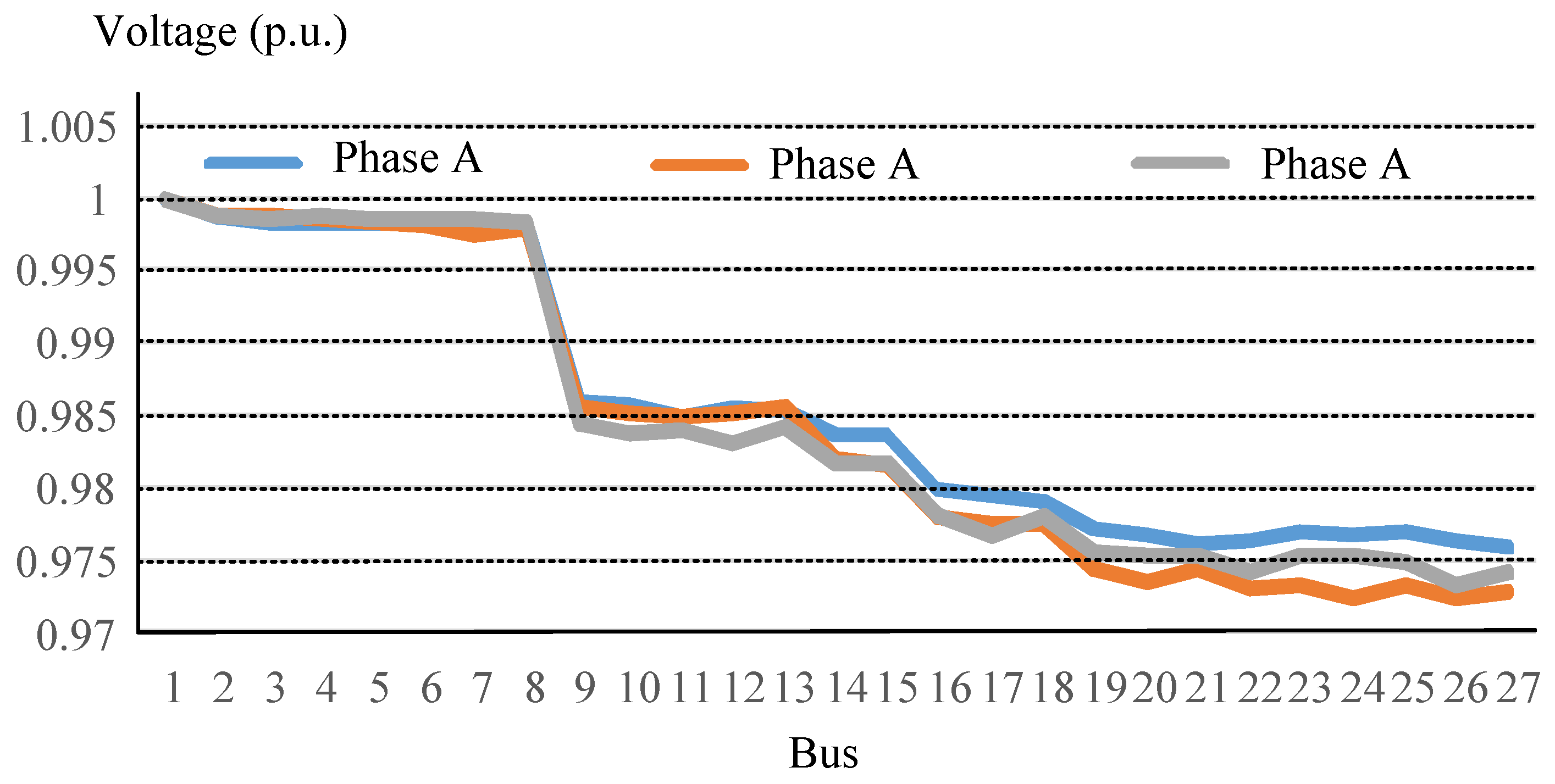
Figure 6 and Figure 7 show the three-phase voltage profiles of each bus before and after the phase rearrangement at the heavy load period (2 pm), respectively. In Figure 6, the minimum voltage of phase A is about 0.943 p.u., which violates the operational constraints. After the phase rearrangement, the minimum voltage of phase A is promoted to 0.976 p.u. and the three-phase voltage profiles of each bus are simultaneously improved to safe operation.
4.2. Unbalance and Loss Improvement
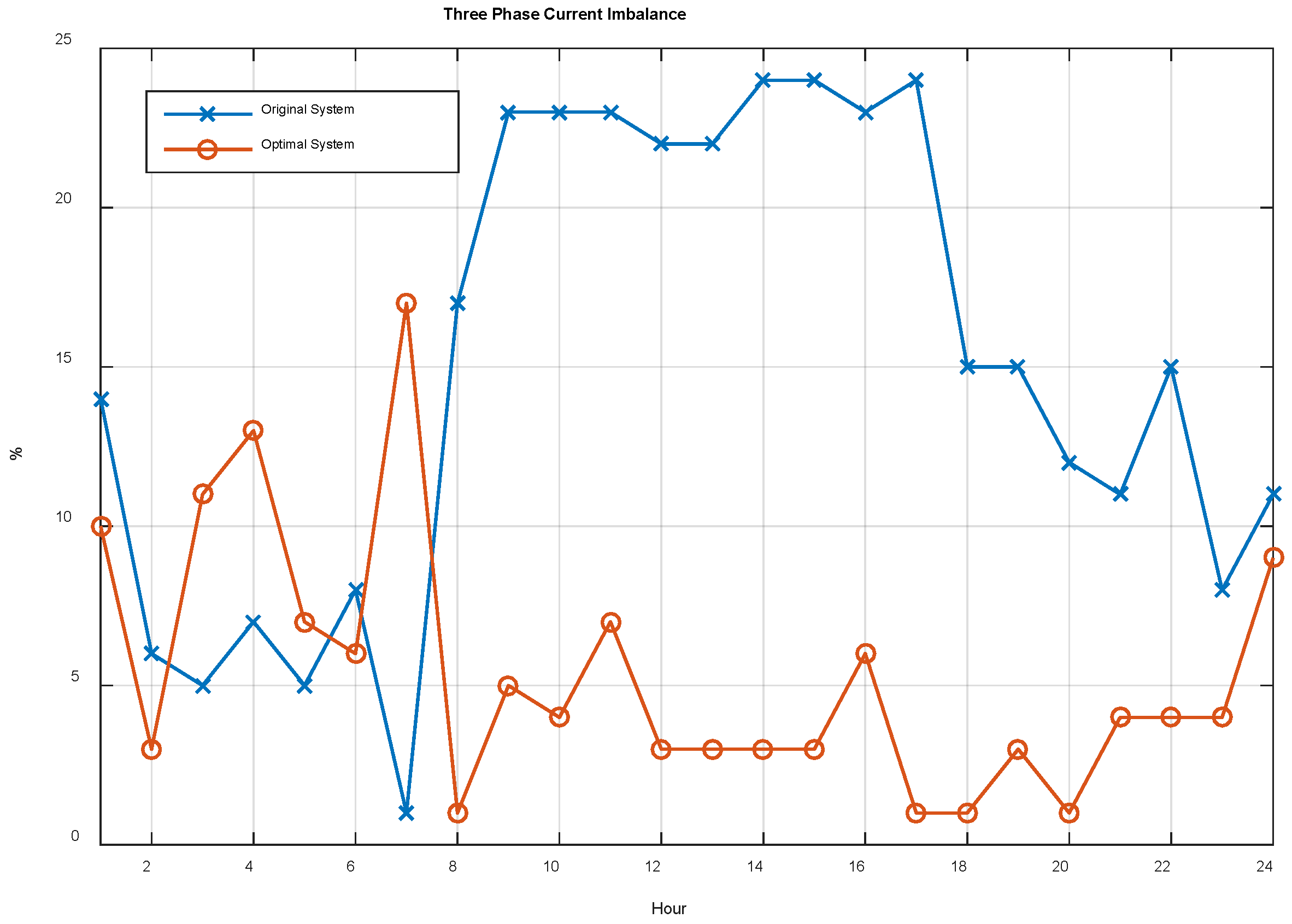
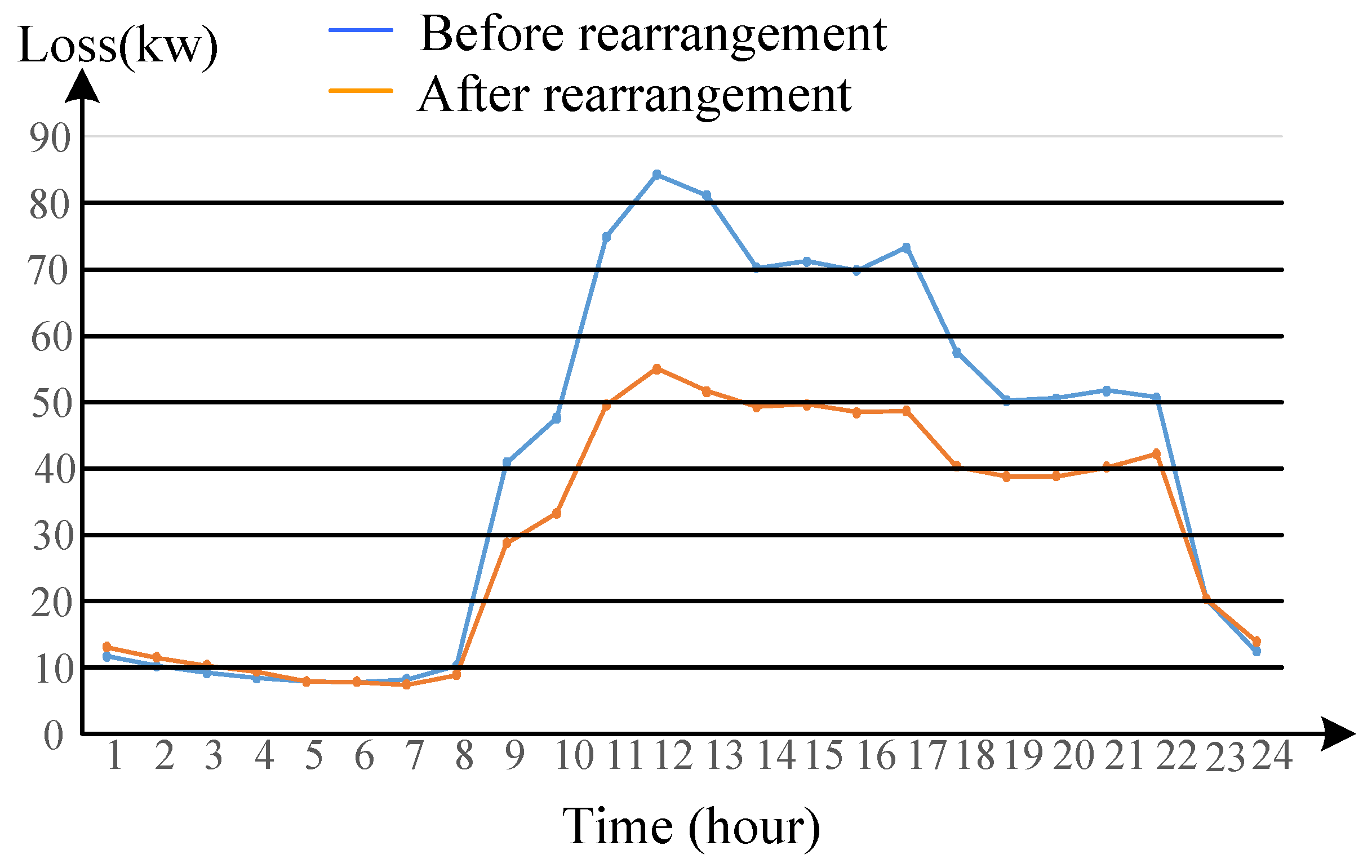
Figure 8 demonstrates the daily system unbalance profiles at the swing bus (bus 1) and Figure 9 is the total line loss profiles at each hour. The unbalance factor between 9 am and 5 pm is much larger than the other periods. The unbalance factor at the peak load was from 23%–24% to 2%–7% by using the phase arrangement of distribution transformers. In Figure 8, it is clearly observed that phase rearrangement introduces a lower unbalance factor than that without phase rearrangement. At the same time, the total line loss is improved and total line loss was also reduced from 980.09 kW to 659.01 kW.
4.3. Convergence Test
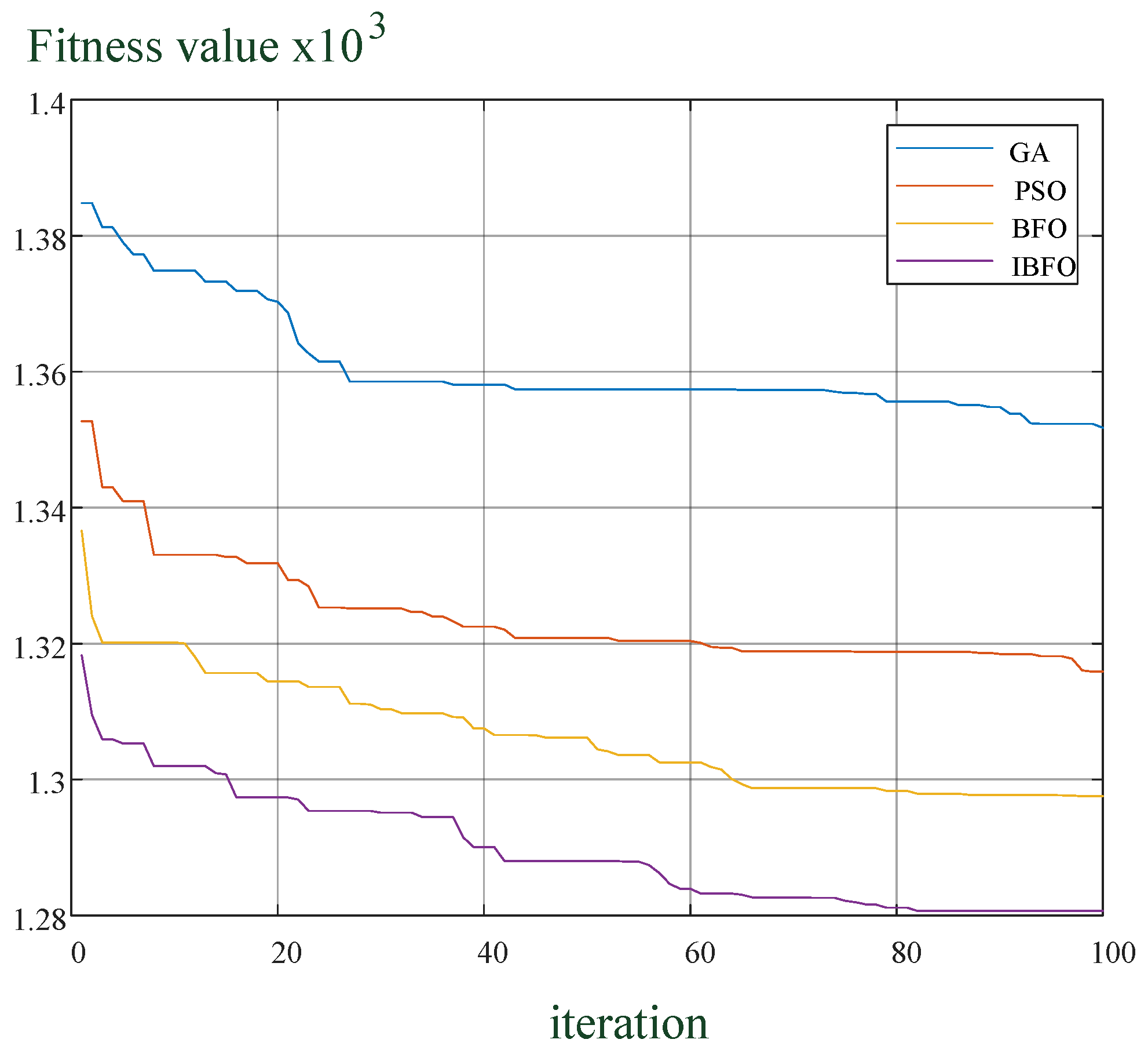
Figure 10 illustrates the convergence characteristics of GA, PSO, BFO, and IBFO. The tests were carried out on an Intel i5-7300HQ 2.5 GHz CPU and 16 GB DRAM memory. We set 100 iterations as the stopping condition for each algorithm. In Figure 10, the fitness value of IBFO can converge to a lower value than other algorithms. The operational time of the IBFO is slightly longer than that of the BFO but faster than GA. Regarding the calculation stability of the optimal solutions, IBFO reach convergence after about 82 iterations and has better convergence than the other algorithms. Table 4 shows the maximum, minimum, and average optimized loss with 100 test runs. In the 100 times of repeated resilience testing, the average converged loss of IBFO, BFO, PSO, and GA are 730.84 kW, 761.16 kW, 826.08 kW and 869.46 kW, respectively. It shows the capacity of IBFO to explore a more likely global optimum than other algorithms. The results show that it is better than the PSO, BFO, or GA, which demonstrates that the IBFO is best.
5. Conclusions
This paper presents an efficient strategy-based IBFO algorithm to find out the optimal phase assignment for the overall transformers in a distribution feeder. The minimal total line loss is formulated as the objective function. IBFO process swaps the phase-type of transformers to accomplish the appropriate arrangement of transformers. According to the optimal phase assignment of the transformer and an actual Taipower distribution feeder, the system losses and unbalance factor are solved by the three-phase load flow analysis. With the advantages of heuristic ideals, IBFO supersedes the conventional ideals threefold: the complicated discrete problem is solvable with better performance and the more likelihood of deriving a global optimum than AI methods. By comparing the other algorithms, IBFO is sufficient evidence to show that the transformer rearrangement method is both effective and efficient. The results show that the unbalance factor and total line loss can be improved by the IBFO algorithm. The IBFO algorithm has great potential for further applications to many other mixed-integer combinational optimization problems in power system planning and operation.
Author Contributions
C.-S.T. is the first author. He provided hardware tools, system model and related materials experimental model results. M.-T.T. generalized novel algorithms and designed system planning projects. All the authors were involved in exploring system validation and results and permitting the benefits of the published document. All authors have read and agreed to the published version of the manuscript.
Funding
This research received no external funding.
Conflicts of Interest
The authors declare no conflict of interest.
Nomenclature
| the equivalent loads for A, B, C phase | |
| the A-phase and B-phase loads connected to the neutral wires | |
| the single-phase loads connected to the two-wire | |
| the three-phase load | |
| per unit load at hour t of load customer i | |
| percentage of hourly energy consumption over a daily period of load customer i | |
| monthly energy consumption of customer i in CIS | |
| the number of monthly days | |
| hourly real power demand of customer i | |
| transformer hourly loading at hour t | |
| the number of customers | |
| the rate of load growth of the customer | |
| the time period of load forecasting | |
| The total line loss of distribution feeders at t-th time | |
| the status of phase arrangement | |
| the total number of branches in the feeder | |
| the voltage of i-th bus | |
| the admittance of branch | |
| the voltage phase angle difference between bus-i and bus-j | |
| upper limit of branch current magnitude | |
| lower/upper limit of bus voltage magnitude () | |
| the neutral line current | |
| the maximal valve of current | |
| the j-th state value of n-th bacterium at the p-th chemotaxis. is the number of bacterial chemotaxis. | |
| the j-th state value of the bacterium, a bacterium combined by J state values into a complete solution | |
| The total number of bacteria | |
| the tumble direction vector of the bacterium | |
| The distance for the bacterium at each step | |
| State value of the n-th bacterium after the p-th chemotaxis | |
| The fitness value of the n-th bacterium at the p-th chemotaxis | |
| The fitness value of the n-th bacterium after the p-th chemotaxis | |
| State value of the n-th bacterium after the (p + 1)-th chemotaxis | |
| The count of the bacterial reproduction | |
| The number of chemotaxis process | |
| The number of bacterial reproduction | |
| The fitness values sorted after the chemotaxis procedure | |
| The count of bacterial elimination | |
| The number of chemotaxis |
References
- Su, Y.S.; Lin, W.M.; Chang, S.C.; Tsay, M.T. Improving the system unbalance and losses of distribution feeders based on transformer rearrangement. In Proceedings of the IEEE Region 10 Conference TENCON, Chiang Mai, Thailand, 24–24 November 2004; Volume 1, pp. 448–451. [Google Scholar]
- Chang, C.Y. Effect of Open-Wye/Open-Delta Transformer and v-v Transformer to the Operation of Distribution System. Master’s Thesis, National Sun Yat-Sen University, Kaohsiung, Taiwan, June 1987. [Google Scholar]
- Chen, T.H.; Chang, J.D. Open wye-open delta and open delta-open delta transformer models for rigorous Distribution system analysis. IET Gener. Transm. Distrib. 1992, 139, 227–234. Available online: https://ieeexplore.ieee.org/document/141497 (accessed on 21 January 2020). [CrossRef]
- Panagiotis, E.; Ekonomou, L. (Eds.) Electricity Distribution, Intelligent Solutions for Electricity Transmission and Distribution Networks; Springer: Berlin/Heidelberg, Germany, 2016; ISBN 978-3-662-49434-9. [Google Scholar] [CrossRef]
- Porumb, R.; Toader, C.; Golovanov, N.; Leonida, T.; Seritan, G. Energy Efficiency Rating of Transformers under Unbalanced Linear Regime. In Proceedings of the Optimization of Electrical & Electronic Equipment—OPTIM, Side, Turkey, 2–4 September 2015; pp. 538–544, ISBN 978-1-4673-7239-8. [Google Scholar]
- Chen, T.H.; Cherng, J.T. Optimal phase arrangement of distribution transformers connected to a primary feeder for system unbalance improvement and loss reduction using a Genetic algorithm. In Proceedings of the 21st International Conference on Power Industry Computer Applications, Connecting Utilities, PICA 99, To the Millennium and Beyond, Santa Clara, CA, USA, 21–21 May 1999. [Google Scholar]
- Singh, D.; Misra, R.K.; Mishra, S. Distribution system feeder re-phasing considering voltage-dependency of loads. Int. J. Electr. Power Energy Syst. 2016, 76, 107–119. [Google Scholar] [CrossRef]
- Abril, I.P. NSGA-II phase balancing of primary distribution circuits by the reconnection of their circuit laterals and distribution transformers. Electr. Power Syst. Res. 2014, 109, 1–7. [Google Scholar] [CrossRef]
- Lin, C.H.; Chen, C.S.; Ku, T.T.; Ho, C.Y. Mitigation of three-phase unbalancing for distribution feeders by rephasing of laterals and distribution transformers. In Proceedings of the IEEE PES T&D Conference, New Orleans, LA, USA, 19–22 April 2010; Volume 1, pp. 1–6. [Google Scholar]
- Huang, S.J.; Tai, T.Y.; Liu, X.Z.; Su, W.F.; Gu, P.H. Application of bird-mating optimization to phase adjustment of open-wye/open-delta transformers in a power grid. In Proceedings of the IEEE International Conference on Industrial Technology (ICIT), Seville, Spain, 17–19 March 2015; Volume 1, pp. 1275–1279. [Google Scholar]
- Ali, B.; Siddique, I. Distribution system loss reduction by automatic transformer load balancing. In Proceedings of the International Multi-Topic Conference (INMIC), Lahore, Pakistan, 24–26 November 2017; Volume 1, pp. 1–5. [Google Scholar]
- Tsay, M.T.; Chan, S.Y. The Optimal Loss Reduction of Distribution Feeder Based on Transformer Rearrangement. Int. J. Electr. Power Energy Syst. 2001, 23, 343–348. [Google Scholar] [CrossRef]
- Tsay, M.T.; Chan, S.Y. Improvement in System Unbalance and Loss Reduction of Distribution Feeders Using Transformer Phase Rearrangement and Load Diversity. Int. J. Electr. Power Energy Syst. 2003, 25, 395–401. [Google Scholar] [CrossRef]
- Passion, K.M. Biomimicry of bacterial foraging for distributed optimization and control. IEEE Control Syst. 2002, 22, 52–67. [Google Scholar]
- Naveen, S.; Kumar, K.S.; Rajalakshmi, K. Distribution system reconfiguration for loss minimization using modified bacterial foraging optimization algorithm. Int. J. Electr. Power Energy Syst. 2015, 69, 90–97. [Google Scholar] [CrossRef]
- Bhushan, B.; Singh, M. Adaptive control of DC motor using bacterial foraging algorithm. Appl. Soft Comput. 2011, 11, 4913–4920. Available online: https://www.sciencedirect.com/science/article/abs/pii/S1568494611002262 (accessed on 21 January 2020). [CrossRef]
- Elattar, E.E. A hybrid genetic algorithm and bacterial foraging approach for dynamic economic dispatch problem. Int. J. Electr. Power Energy Syst. 2015, 69, 18–26. [Google Scholar] [CrossRef]
- Saad, N.H.; El-Sattar, A.A.; Marei, M.E. Improved bacterial foraging optimization for grid connected wind energy conversion system based PMSG with matrix converter. Ain Shams Eng. J. 2018, 9, 2183–2193. [Google Scholar] [CrossRef]
- Fitriyanah, D.N.; Abadi, I. Fuzzy Logic Control Design of Mobile PV Using Bacterial Foraging Optimization. In Proceedings of the 2018 International Seminar on Intelligent Technology and Its Applications (ISITIA), Bali, Indonesia, 30–31 August 2018; Volume 1, pp. 1–5. [Google Scholar]
- Xiong, X.; Wu, W.; Li, N.; Yang, L.; Zhang, J.; Wei, Z. Risk-Based Multi-Objective Optimization of Distributed Generation Based on GPSO-BFA Algorithm. IEEE Access 2019, 7, 30563–30572. [Google Scholar] [CrossRef]
- Chen, H.; Luo, J.; Xu, Y.; Wu, C.; Li, C.; Zhang, Q. Chaos Enhanced Bacterial Foraging Optimization for Global Optimization. IEEE Access 2018, 6, 64905–64919. [Google Scholar]
- Zhao, W.; Wang, L. An effective bacterial foraging optimizer for global optimization. Inf. Sci. 2016, 329, 719–735. [Google Scholar] [CrossRef]
- Zhao, F.; Si, J.; Wang, J. Research on optimal schedule strategy for active distribution network using particle swarm optimization combined with bacterial foraging algorithm. Int. J. Electr. Power Energy Syst. 2016, 78, 637–646. [Google Scholar] [CrossRef]
- Nithya, S.; Jeyanthi, K.M. Genetic algorithm based bacterial foraging optimization with three-pass protocol concept for heterogeneous network security enhancement. J. Comput. Sci. 2017, 21, 275–282. [Google Scholar] [CrossRef]
- Chalermchaiarbha, S.; Ongsakul, W. Stochastic weight trade-off particle swarm optimization for nonconvex economic dispatch. Energy Convers. Manag. 2013, 70, 66–75. [Google Scholar] [CrossRef]
- Lin, W.M.; Teng, J.H. Three-phase distribution network fast-decoupled power flow solutions. Int. J. Electr. Power Energy Syst. 2000, 22, 375–380. [Google Scholar] [CrossRef]
- Chaturvedi, K.T.; Pandit, M.; Srivastava, I. Self-organizing hierarchical particle swarm optimization for nonvex economic dispatch. IEEE Trans. Power Syst. 2008, 23, 1079–1087. [Google Scholar] [CrossRef]
Figure 1.
The loads of Open-Wye/Open Delta transformer.

Figure 2.
The flowchart of improved bacterial foraging algorithm (IBFO) applied.

Figure 3.
The practical feeder diagram.

Figure 4.
The three-phase voltage profiles of each bus before phase rearrangement at the light load period.
Figure 4.
The three-phase voltage profiles of each bus before phase rearrangement at the light load period.

Figure 5.
The three-phase voltage profiles of each bus after phase rearrangement at the light load period.
Figure 5.
The three-phase voltage profiles of each bus after phase rearrangement at the light load period.

Figure 6.
The three-phase voltage profiles of each bus before the phase rearrangement at the heavy load period.
Figure 6.
The three-phase voltage profiles of each bus before the phase rearrangement at the heavy load period.

Figure 7.
The three-phase voltage profiles of each bus after the phase rearrangement at the heavy load period.
Figure 7.
The three-phase voltage profiles of each bus after the phase rearrangement at the heavy load period.

Figure 8.
The daily system unbalance profiles at the swing bus (bus 1).

Figure 9.
The total line loss profiles.

Figure 10.
The convergence characteristics of genetic algorithm (GA), particle swarm optimization (PSO), bacterial foraging optimization (BFO), and IBFO.
Figure 10.
The convergence characteristics of genetic algorithm (GA), particle swarm optimization (PSO), bacterial foraging optimization (BFO), and IBFO.


Table 1.
The possible connection schemes of transformers.
| Type | Open-Wye/Open Delta Transformer | Single-Phase Transformer | |||||||
|---|---|---|---|---|---|---|---|---|---|
| 1 | A | B | C | A | B | × | A | × | × |
| 2 | A | C | B | A | × | C | × | B | × |
| 3 | B | A | C | × | B | C | × | × | C |
| 4 | B | C | A | - | - | - | - | - | - |
| 5 | C | A | B | - | - | - | - | - | - |
| 6 | C | B | A | - | - | - | - | - | - |
Table 2.
Summary of distribution transformer.
| Transformer Type | The No. of Transformer | Total Capacity (KVA) |
|---|---|---|
| Three-phase | 7 | 3500 |
| Open-Y/open- | 10 | 5000 |
| Single-phase | 1 | 100 |
| Total | 18 | 8600 |
Table 3.
The optimal phase connected to distribution transformers.
| Bus No. | Transformer Type | Original Connected | Phase Rearrangement |
|---|---|---|---|
| 3 | A,B | - | |
| 4 | A,B | B to C, C to A | |
| 6 | A,B,C | - | |
| 7 | A,B | - | |
| 8 | A,B,C | A to C, -, C to A | |
| 10 | A,B,C | A to C, -, C to A | |
| 11 | A,B,C | A to C, -, C to A | |
| 12 | A,B,C | - | |
| 13 | B,C | -, C to A | |
| 15 | A,B | A to C, - | |
| 17 | A,B,C | A to B, B to C, C to A | |
| 18 | B,C | - | |
| 20 | A,B,C | -, B to C | |
| 21 | A,C | A to C, C to B | |
| 24 | B,C | B to A, C to B | |
| 25 | B | - | |
| 26 | A,B | - | |
| 27 | A,B | A to C, - |
Note: A to C is changed from phase-A connection to phase-C connection.
Table 4.
The comparison of GA, PSO, BFO, and IBFO.
| GA | PSO | BFO | IBFO | |
|---|---|---|---|---|
| Maximum converged loss (kW) | 1031.12 | 969.09 | 906.98 | 854.80 |
| Minimal converged loss (kW) | 695.57 | 677.11 | 667.68 | 659.01 |
| Average converged loss (kW) | 869.46 | 826.08 | 761.16 | 730.84 |
| CPU time (sec) | 84.81 | 48.67 | 60.82 | 69.94 |
© 2020 by the authors. Licensee MDPI, Basel, Switzerland. This article is an open access article distributed under the terms and conditions of the Creative Commons Attribution (CC BY) license (http://creativecommons.org/licenses/by/4.0/).
Share and Cite
MDPI and ACS Style
Tu, C.-S.; Tsai, M.-T. Optimal Phase Arrangement of Distribution Transformers for System Unbalance Improvement and Loss Reduction. Energies 2020, 13, 545. https://doi.org/10.3390/en13030545
AMA Style
Tu C-S, Tsai M-T. Optimal Phase Arrangement of Distribution Transformers for System Unbalance Improvement and Loss Reduction. Energies. 2020; 13(3):545. https://doi.org/10.3390/en13030545
Chicago/Turabian StyleTu, Chia-Sheng, and Ming-Tang Tsai. 2020. "Optimal Phase Arrangement of Distribution Transformers for System Unbalance Improvement and Loss Reduction" Energies 13, no. 3: 545. https://doi.org/10.3390/en13030545
Note that from the first issue of 2016, this journal uses article numbers instead of page numbers. See further details here.