Hydrodynamic Investigation of a Dual-Cylindrical OWC Wave Energy Converter Integrated into a Fixed Caisson Breakwater


1
College of Shipbuilding Engineering, Harbin Engineering University, Harbin 150001, China
2
College of Transportation Engineering, Dalian Maritime University, Dalian 116026, China
3
Key Lab of Structures Dynamic Behavior and Control of the Ministry of Education, School of Civil Engineering, Harbin Institute of Technology, Harbin 150090, China
4
State Key Laboratory of Coastal and Offshore Engineering, Dalian University of Technology (DUT), Dalian 116024, China
*
Author to whom correspondence should be addressed.
Energies 2020, 13(4), 896; https://doi.org/10.3390/en13040896
Submission received: 13 January 2020
/
Revised: 6 February 2020
/
Accepted: 8 February 2020
/
Published: 18 February 2020
(This article belongs to the Special Issue Design and Implementation of Control Schemes for Wave Energy Systems)
Abstract
:A fixed dual cylindrical oscillating water column (OWC) acting as a breakwater-type wave energy converter (WEC) is proposed to harvest the wave energy effectively for shallow offshore sites. An analytical model is developed to investigate the hydrodynamic characteristics and the energy capture capacity of the cylindrical OWC device in severe waves. Based on the linear potential flow theory, the analytical solutions of the velocity potential in diffraction mode are solved by matching the Eigen-function expansion technique, and the continuous conditions of the velocity potential and fluid velocity between the computational sub-domains are involved in solving the problem for determining a solution. The proposed model is verified against the published data. The effects of the wave height, the angle of chamber clapboard and the radius of the inner and outer cylindrical column on the energy conversion efficiency are investigated in this paper. To improve the energy conversion performance and obtain a faster prediction for structural optimization of the cylindrical OWC, the geometrical parameters are further discussed in the analytical model. The results indicate that the geometrical parameters of the chamber have significant effects on the wave energy absorption efficiency. It is found that the effective frequency bandwidth of the dual cylindrical column can be broadened by improving the angle of the chamber clapboard and the inner–outer cylinder diameter ratio.
1. Introduction
Ocean renewable energy as one of the clean and low-carbon energies has drawn wide attention in recent years of all circles. Because of the advantages gained due to the high energy density and the wide distribution, a growing number of studies conducted by researchers and engineers focused on energy extraction from ocean waves [1,2]. There has been a wide range of wave energy converters proposed to improve the energy trapping performance, and some of them have been successfully applied to commercialization. Owing to the capability of high energy conversion, adaptability to the seabed bathymetry, structural simplicity and reliability of safety operation, the oscillating water column (OWC) device is considered to be the most widely used and promising wave energy converters [3,4].
However, the high construction expenses and generation cost still significantly impedes wave energy utilization development and its industrial application. Accordingly, a large number of developers and designers have focused on the construction-cost reduction. The idea of the integration of the breakwater and the wave energy converters (WECs) was first proposed by Graw [5]. H. Ohneda et al. integrated a 60KW OWC device with a shoreline breakwater, which deployed into the sea firstly in 1990 at the port of Sakata in Japan [6]. After that, a series of shoreline bottom-fixed OWCs have been proposed and tested in prototype, such as LIMPET (500 KW) in England [7], the Picoplant (400 KW) in Portugal [8], the Mutrikuplant (296 KW) in Spain [9], the shoreline OWC (100 KW) in China [10]. Due to the similar structural dimensions, material characteristics and geological conditions, combining the OWCs to existing breakwater structures can simultaneously achieve wave energy utilization and wave attenuation. The benefits obtained from the cost-sharing integrated system can also improve the stability of the breakwater and naturally lead to cost reduction.
Recently, the theoretical and experimental studies focused on the integrations of OWCs, and caisson-type breakwaters have been made. Boccotti [11,12,13] conducted the theoretical investigation associated with the caisson breakwater integrating into an OWC device, and the related experimental results showed very good agreement with the theoretical calculation. Shi et al. [14] proposed a new structure of shore-type OWC integrated into the caisson breakwater and results showed that the air motion in the caisson is related to the incident wave period. Boccotti [15] added an additional vertical duct at the wave-beaten side based on the traditional OWC and found that this U-OWC device can achieve higher conversion efficiency than before. Tanimoto et al. [16] compared the stability of different structural types for caisson breakwaters in the numerical model and proved that the cylinder-type caisson breakwater is more reliable, especially for severe wind-wave conditions. Spyros A. Mavrakos et al. [17] investigated the hydrodynamic forces and motions on the concentric vertical cylinders, a series of experiments concerning concentric cylinders arrangements were conducted to study the first- and second-order exciting wave forces and wave elevations at specific locations around the bodies. Thomas Mazarakos et al. [18] focused on the hydro-aero-elastic coupling analysis of the multipurpose floating structures for offshore wind and wave energy exploitation, the problems of diffraction and motion-dependent radiation problems around the floating structure have been investigated. Deng et al. [19] numerically investigated an OWC with a V-shaped channel, and results show that the wing walls can significantly increase the conversion efficiency of the OWC. Chen et al. [20] experimentally investigated the effects of different wave conditions on the hydrodynamic performance of an improved double cylinder caisson-OWC model. It is understood that the study of the mechanical mechanism for complicated structures under wave actions are often limited by physical tests; thus, it is necessary to conduct the theoretical study to improve the understanding of hydrodynamic behavior of the OWC structures in waves and provide an optimal method to enhance the OWC wave extraction performance.
In this paper, the hydrodynamic performance and the energy extraction efficiency of the hybrid OWC device are investigated in an analytical model by using the potential flow theory method. The matching Eigen-function expansion method is applied to solve the radiation-diffraction problems. The calculated hydrodynamics of the integrated caisson-OWC system are also compared and analyzed with the published results. In addition, the effects of the regular wave incidence parameters, the angle between the baffles in the chamber and the radius of the inner and outer cylinder are further discussed for the optimization of the hybrid oscillating water column caisson. This paper is organized as follows: Section 2 describes the mathematical formulas, including the boundary value problem and the mathematical solutions. In Section 3, the analytical models are validated against corresponding published data, followed by the discussion of the calculation results. Section 4 presents the conclusions.
2. Mathematical Model
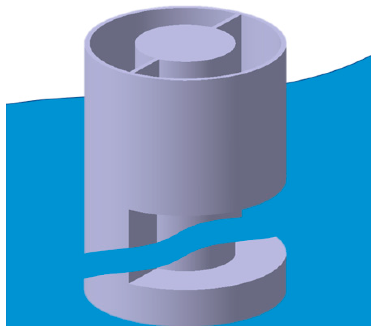
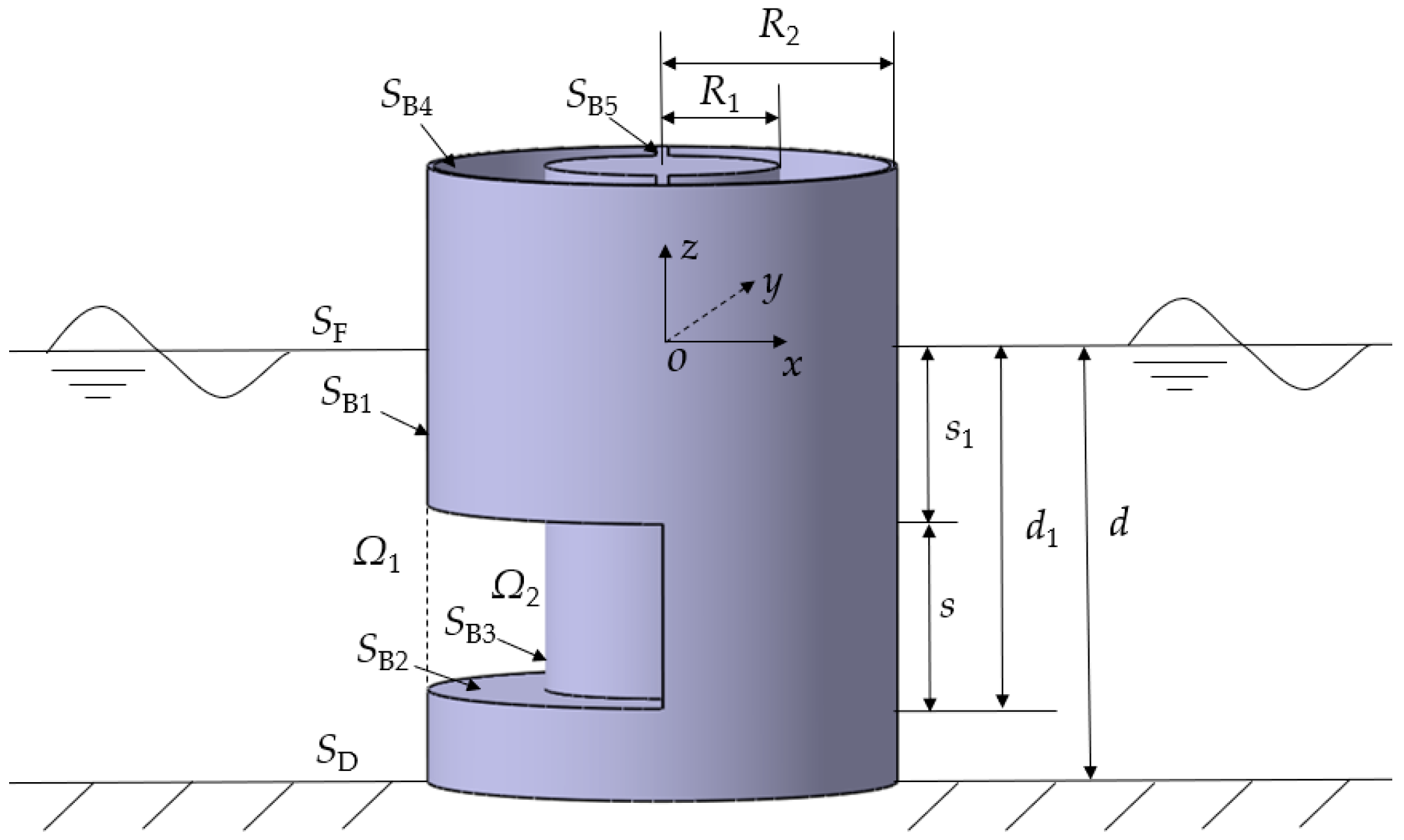
As shown in Figure 1, a dual-cylindrical OWC-WEC structure (i.e., caisson type breakwater) with two concentric cylindrical shells is fixed in the sea. The inner shell of the submerged model proposed in this paper can be considered as a solid cylinder. The hemi-toroidal outer wall, two rectangular baffles between the cylindrical shells and the inner wall part jointly form an air chamber for water column oscillation. The offshore side column of the dual-cylindrical structure is filled with sand, and a fixed pedestal at the bottom is introduced for caisson stability. A semi-arc inlet is selected on the onshore side of the outer wall, which can determine the height of the chamber for the proposed OWC-WEC model. In this study, the water depth is constant 0.3 m, the height of the pedestal is 0.75 m, the semi-arc inlet breadth is 0.15 m, the immersion depth of the structure is 0.3 m, the angle of the semi-arc inlet between the baffles is 90°. The inner and outer cylinder shell have the diameters D1 and D2, respectively. A three-dimensional Cartesian coordinate system (o-xyz) is defined with the center of origin o locating at the cross-point of the undisturbed water plane, x-axis directing along the propagation of the incident waves, and z-axis orientating vertical upwards as the positive direction.
2.1. Power Take-off Model
The wave energy extraction efficiency ξ can be calculated as:
Here, EA is the absorbed power of the OWC device, and EI is the flux of the incidence wave energy, which can be theoretically calculated [21,22]
With the flux coefficient n, which can be expressed as:
The air is assumed to be incompressible in this paper, the air flow rate Q(t) can be considered as the air volume variation rate in the chamber; thus, the calculation of EA can be written as [23]
where Sφ is the sectional area of the air chamber, Vφ (t) is the vertical speed of the water surface in the air chamber, Ba is the damping coefficient.
In order to calculate the wave energy extraction efficiency ξ in this power take-off model, the velocity potential involved in the diffraction and radiation problems according to the potential-flow theory should be solved first. The relative dimensional parameters, including the water depth d, wave number k, gravitational acceleration g, incident wave amplitude A, water density ρ and the device structure geometric parameters (details see Table 1), are fixed parameters in this analysis.
2.2. Boundary Value Problem
The potential-flow theory is used to solve the diffraction-radiation problem, the dual-cylindrical OWC structure can be simplified and is shown in Figure 2. According to the geometric characteristic of the structure, the fluid domain can be divided into two subdomains. To be specific, the external subdomain Ω1 is defined by r ≥ R2 and −d ≤ z ≤ 0, the internal subdomain Ω2 is by R1 ≤ r ≤ R2 and −d1 ≤ z ≤ 0, respectively. Correspondingly, the Φ1 and Φ2 represent the velocity potentials in Ω1 and Ω2.
To calculate the three-dimensional steady flow potential in this analytical model, the time-space separation method is involved to assume that all the time-dependent variables are considered to be harmonic in the problem. The velocity potential in the whole domain is expressed as:
where t denotes time, i is the imaginary number, ω is the angular frequency, is a spatial velocity potential, and r, θ, z represents the coordinates in cylindrical coordinate system for radial, azimuthal and vertical directions, respectively Re[ ] denotes taking the real part of a complex equation.
It is assumed that the fluid is inviscid, incompressible and flow-irrotational, the velocity potential in the linearized boundary value problem satisfies the governing Laplace equation and its boundary conditions as follows:
in which SD, SF, SB represent the seabed, external free surface and mean wet body surface, respectively.
In order to solve the above boundary value problem, the velocity potential in two divided subdomains Region 1 and Region 2 with corresponding Φ1 and Φ2 can be written as:
For Φ2, the corresponding boundary value problem can be written as follows:
According to the matching continuous conditions of the flow fluid, the intensity of pressure continuous condition and the velocity continuous condition on the interfaces can be described as:
where d1 is the height from free surface to the lower edge of the inlet, s is the submergence height of the top edge of the inlet and denotes the radial partial derivative of the variable.
2.3. Mathematical Solutions
Based on the method of variable separation approach, the expression of the velocity potential for Region 1 (, ) and Region 2 (, ) can be constructed in a cylindrical coordinate system as follows:
where Amn, Bmn and Cmn are the constant coefficients, εm is the Neumann symbol as εm = {1, m = 0; 2, m ≥ 0}, with A as the wave amplitude, g the gravitational acceleration, ω the angular frequency, Jm the Primal Bessel function, Km the modified Bessel function of the second kind, Hm the Hankel function, Hm(1) the Primal Hankel function, Hm(2) the Hankel function of the second-kind and Im the Primal modified Bessel function, all of order m. Expressions of Pmn and Qmn are shown as follows:
Here, kn is the positive real root of Equation (27), the vertical Eigen-function Zn (z) can be obtained according to the boundary conditions and expressed as
The continuous matching conditions of Region Ω1 and Ω2 applied on the adjacent subdomains interfaces and body surface boundary conditions can be rewritten as:
By using the orthogonality condition of the vertical Eigen-functions, after substituting the velocity potential Φ1 and Φ2 into the continuous matching conditions (Equations (29)–(33)), the following equations containing the coefficients of the unknown terms can be rewritten as:
in which the coefficients a0n and ann can be expressed as:
where .
3. Results and Discussion
3.1. Validation
First, in order to validate the present analytical model, two cases with R2/d =1.0 and 2.0 were considered to compare the hydrodynamic force between the analytical solution and the numerical results [24]. In the present analytical model, the height of the semi-arc inlet and the angle between the two baffles were set to zero, the wave height H is 0.06 m and the water depth d is 0.3 m. Figure 3 shows the comparison results of the horizontal wave force and wave moment with different kd. It can be seen that results calculated by the present analytical solution model have a good agreement with the results obtained by MacCamy and Fuchs [24]. The maximum differences of the wave force and the wave moment between the two methods are 1.4% and 3.3%, respectively.
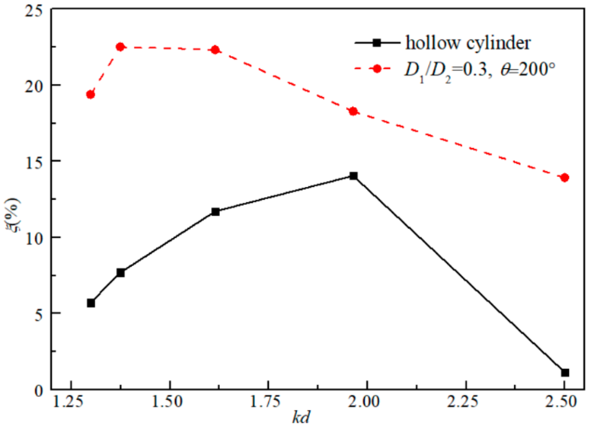
Then, in order to investigate the improvement of the proposed OWC on the wave energy capture ability, a case study on the comparison of the conversion efficiency ξ between the hollow cylinder type and the dual-cylindrical OWC with the relative diameter ratio D1/D2 = 0.3 and the baffle wall angle θ = 200° was carried out, the results are shown in Figure 4. It can be found that the proposed dual-cylinder OWC device (with the normal case of D1/D2 = 0.3 and θ = 200°) can obviously improve the efficiency of wave energy conversion. And for further study of the improvement of the power extraction efficiency, the impact of the OWC geometrical properties will be discussed in Section 3.
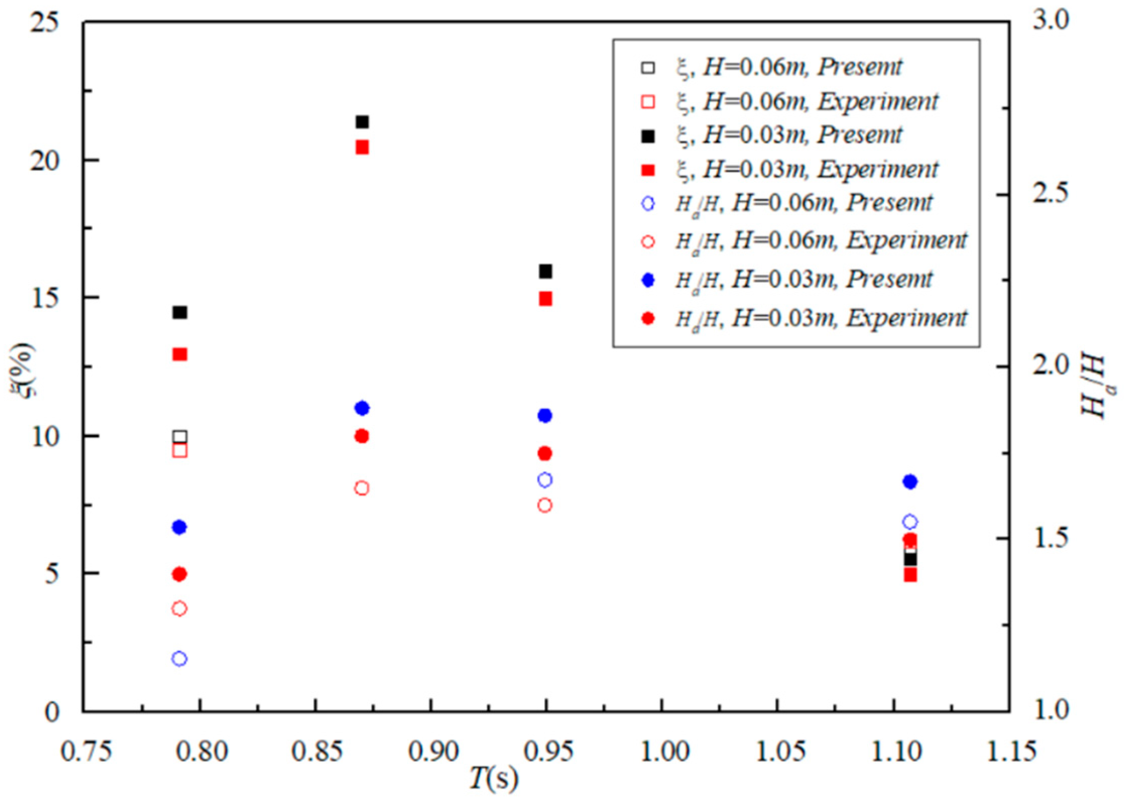
Furthermore, the wave energy conversion efficiency ξ is verified against the experimental results obtained by previous work in our group [20]. The tank tests were performed in the basin of the State Key Laboratory of Coastal and Offshore Engineering in Dalian, China. The basin was 40 m long, 24 m wide, and 1 m in depth. The water depths were 0.3 m, the incident wave heights were 0.03–0.06 m, and wave periods were from 0.7 to 1.1s. The details about the scaled model properties were given in Ref. [20]. The geometrical parameters s = 0.15, d1 = 0.225 m, R1/R2 = 0.5, θ = 180° are fixed in the validation. Two different wave heights of H = 0.03 m and H = 0.06 m are considered in the analytical model. The wave energy conversion efficiency of the device with different wave height ratios Ha/H was calculated in the range of T = 0.791–1.107s, allowing the wave conditions to keep consistent with the experimental tests [20]. Comparisons between the analytical solution and the experimental results are presented in Figure 5. Black and red diamond markers indicate the results of the energy conversion efficiency (the left axis), and the blue and red circle markers represent the Ha/H values (the right axis). The analytical model shows a good agreement with the measured data, with the mean relative error of ξ, and Ha/H between the measured and calculated values are 3.68% and 4.8% for H = 0.06 m, and 8.45% and 7.92% for H = 0.03 m, respectively. The larger difference at small wave periods (see Figure 5) could be due to the ignorance of the air pressure force in the air nozzle area in the analytical model.
3.2. Hydrodynamic Characteristics Inside the OWC Chamber
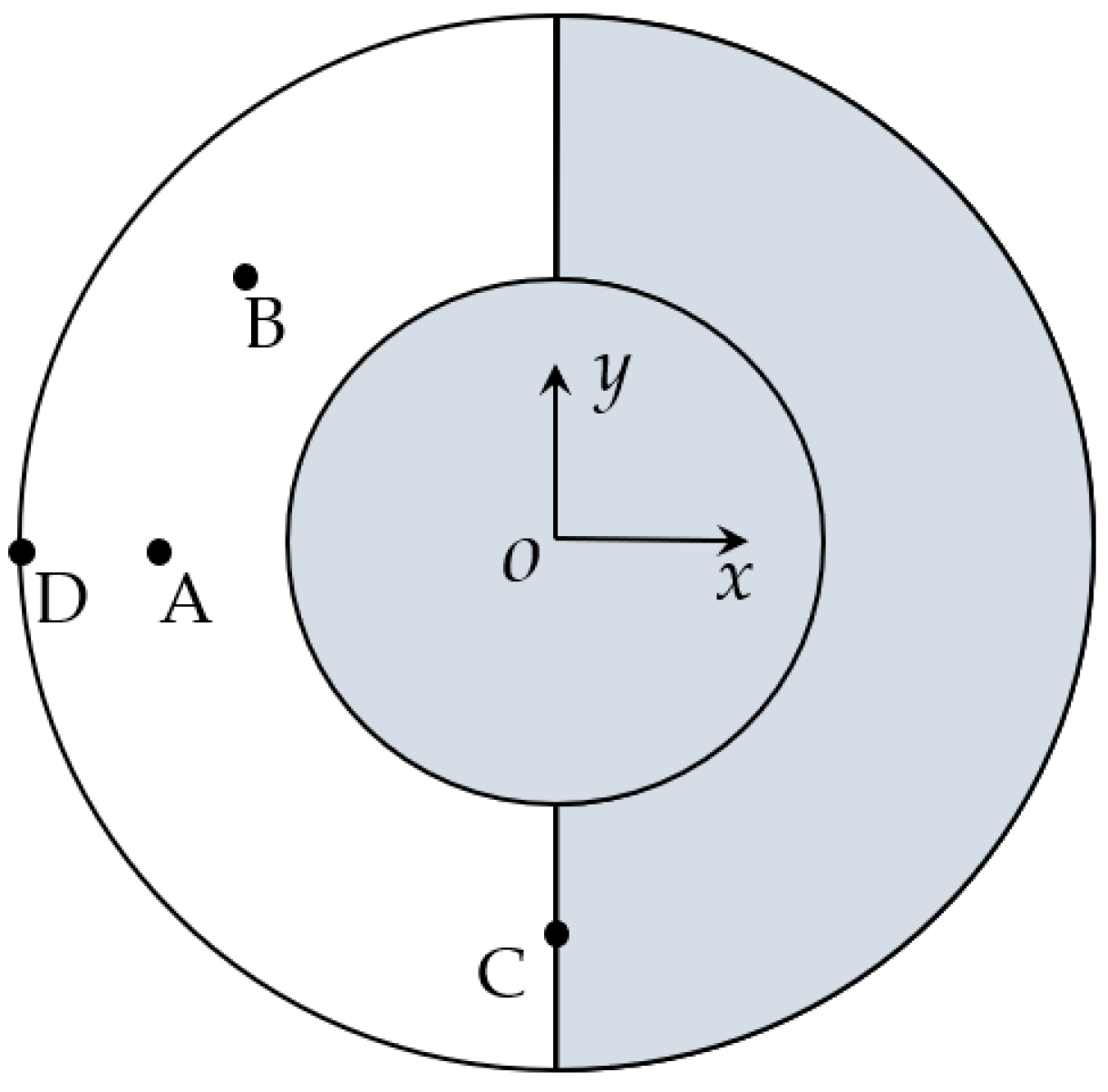
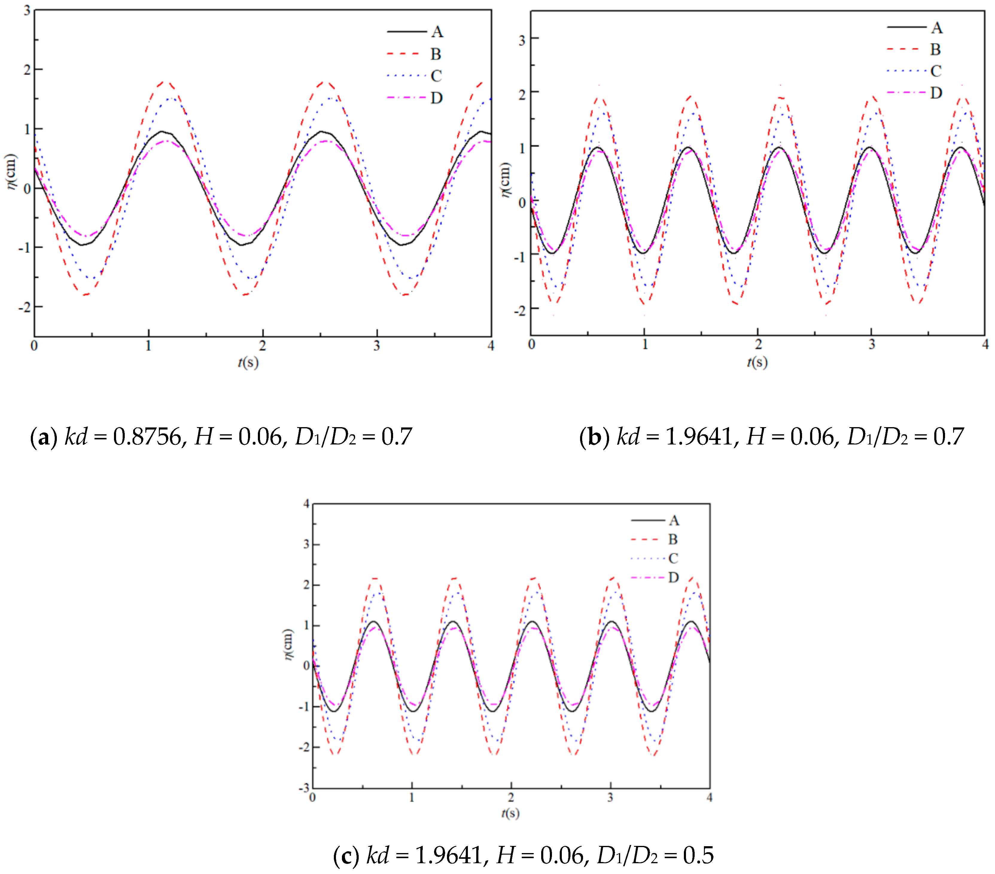
In this section, the wave elevation of the free surface in the semi-arc air chamber is studied. The parameters in the analytical model are set as d/h = 0.6, R1/h = 0.38, h = 0.5 m and H = 0.06 m. The incident wave angle is 0° between the x-axis and the wave propagation direction. Figure 6 shows the time series of the wave surface oscillating at four positions A (−D2/4 − D1/4, 0), B (−D2/8 − D1/8, D2/8 + D1/8), C (0, −D2/4 − D1/4) and D (−D2/2, 0) inside the chamber. Three non-dimensional wave number kd with different geometric characteristics for typical cases of C1 (D1/D2 = 0.7, kd = 0.8756), C2 (D1/D2 = 0.7, kd = 1.9641) and C3 (D1/D2 = 0.5, kd = 1.9641) are calculated to investigate the wave height variation in the chamber of the device.
It can be seen from Figure 7 that the water surface oscillating at different positions in the chamber varies in the same period with slight differences of the oscillating phase for points A–D, whilst the variation of the oscillating amplitudes between each point is great. In the air chamber of the OWC device, among the selected four points A, B, C and D, the water elevation amplitude at points B and C are larger than that at points A and D, which are located near the inlet section along the wave incidence direction. The surface amplitude at B is slightly larger than that at C (point on the baffle wall), which is because of the superposition of the reflected wave and incident wave at position B in the chamber. The water surface elevation at D (point on the interface of inlet) is the lowest, and the surface amplitude at point A inside the chamber is comparatively larger than that at D. The oscillation amplitude is relatively large at C2 and C3 compared with condition C1 due to the larger dimensionless wave number kd; the water motions at points A–D are mostly in phase in the air chamber. When the inside chamber volume is smaller (D1/D2 = 0.7), the water elevation amplitude at point D is close to that at point A for shorter waves, as shown in Figure 7b.
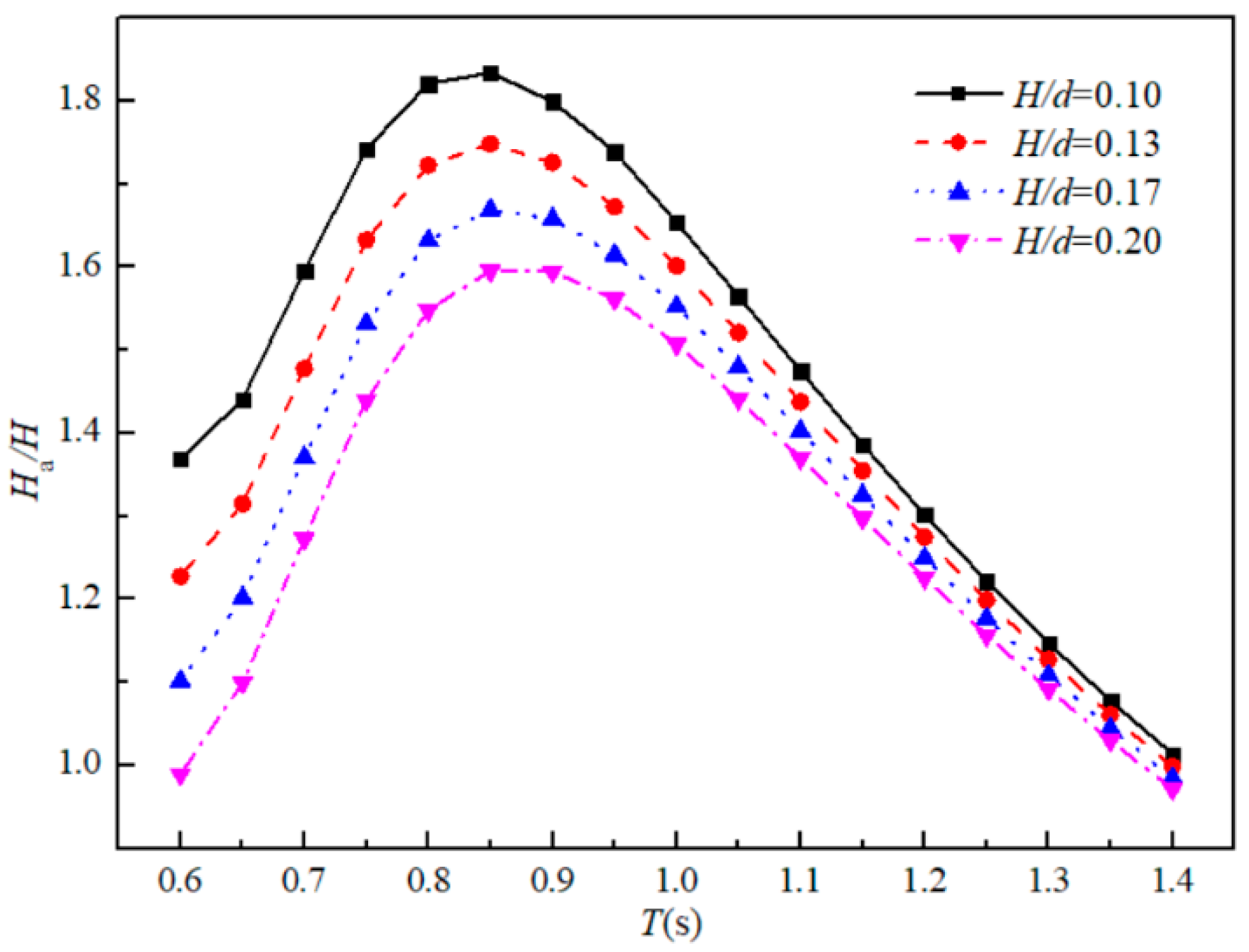
For further investigation of the water motion inside the OWC air chamber, the wave height of the free-surface Ha inside the chamber is normalized by the incidence wave height H. The analytical results of the dimensionless parameter Ha/H with different wave periods are shown in Figure 8. Four different incident wave heights, H/d = 0.1, 0.13, 0.17, and 0.2, are considered in the analytical model. It can be seen from the figure that the wave height of the free-surface inside the chamber increases with the increasing wave period until reaching a local maximum at T = 0.85 s, and then starts to decrease. This is because the conversion wave energy increases with the increment of the wave period for shorter waves, which results in a higher wave elevation inside the air chamber. However, when the water surface elevation increases to a certain extent, the air volume of the upper part in the chamber reduces evidently, resulting in stronger compression of the air and increased the pressure above the water surface, which leads to a restriction for the growing wave elevation inside the chamber. This illustrates that the cylindrical OWC device has the optimum conversion efficiency at a certain incident wave period. Meanwhile, for a fixed wave period condition, the relative wave height Ha/H increases with the decrease of the incident wave height. Again, an explanation can be made that the larger wave height increases the pressure intensity inside the chamber, and then the compression of the air will perform a reaction formation on the water surface. It can also be observed in the experimental results obtained in our previous work [20].
3.3. Effects of Relative Diameter on Conversion Efficiency and Hydrodynamic Loads
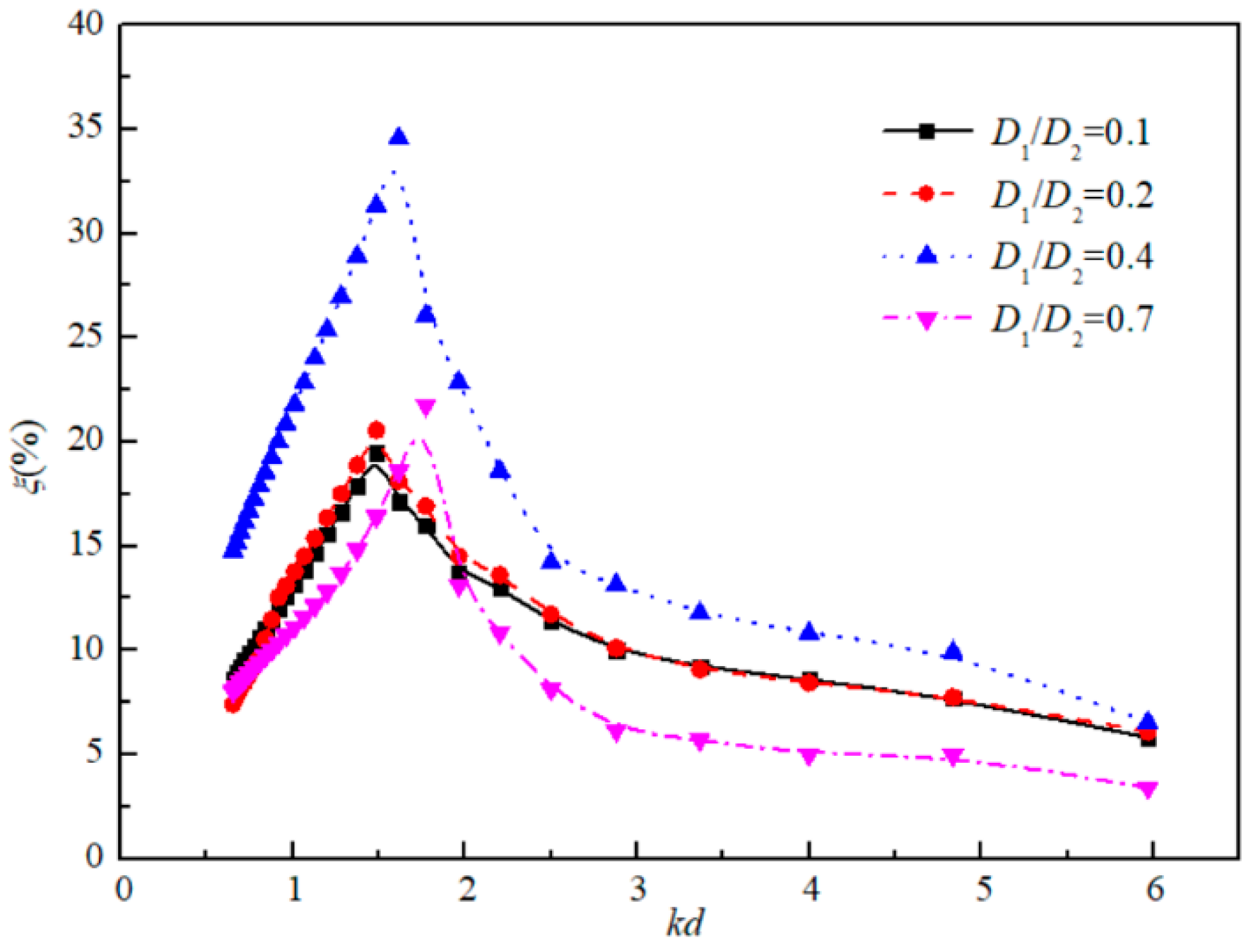
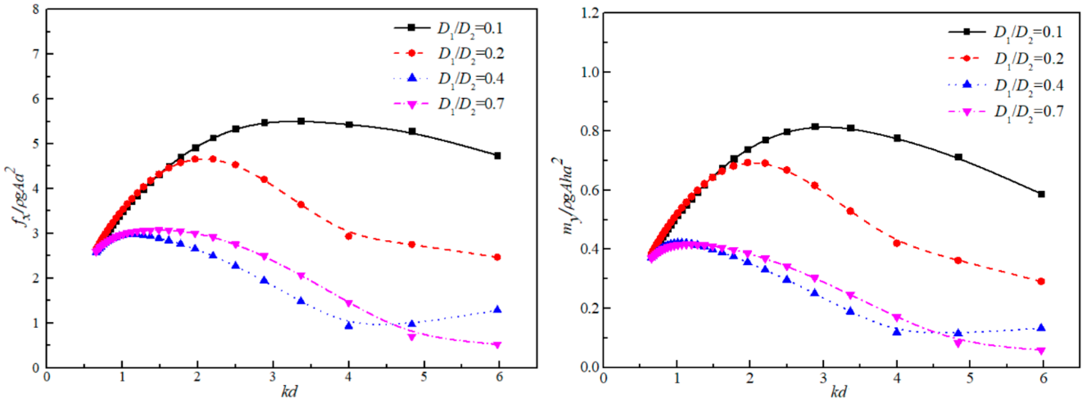
The extraction efficiency and the caisson stability are the critical factors for the integrated OWC optimization. The volume of the air chamber of the OWC device is mainly determined by the inner and outer cylinder diameters. To be specific, in this section, the main structural parameters: the angle between the baffle wall, the outer cylinder diameter and the submergence height of the inlet top edge are set as constant θ = 180°, D2 = 380 mm and s/h = 0.3, respectively. The incident wave height is H = 0.06 m in the analytical model. Four cylinder diameters D1/D2 = 0.1, 0.2, 0.4, and 0.7 are considered as the typical conditions to calculate the conversion efficiency of the OWC device for the considered range of kd.
Figure 9 shows the effect of different inner and outer diameters on the conversion efficiency of the OWC. The conversion efficiency ξ increases with the increasing kd until reaching a local maximum peak and then decreases. The results illustrate that for each condition of the fixed cylinder diameters D1/D2, the optimal conversion efficiency of the OWC has its unique corresponding kd. As shown in the Figure, this particular wave excitation period is related to the geometry parameter D1/D2. Additionally, it also can be found that the corresponding kd for the maximal efficiency increases with the increase of the ratio D1/D2 (the chamber volume decrease). In other words, with the increase of the ratio D1/D2, the peak value caused by the resonance mode shifts towards the shorter period region.
Meanwhile, with the increasing of the diameter ratio of the inner and outer cylinder, the corresponding maximal conversion efficiency ξ of the device increases first and then decreases, as is shown in Figure 9. The maximum wave energy conversion efficiency occurs at the condition of D1/D2 = 0.4. The results of the calculated conversion efficiency against different wave number kd for D1/D2 = 0.1 and 0.2 are similar, and the peak value of the conversion efficiency ξ at D1/D2 = 0.2 is relatively close to that at D1/D2 = 0.7. This is due to the fact that when the area of the air inlet S0 at the top of the chamber is fixed, the larger air chamber volume between the two cylinders could be regarded as an approximately enclosed space; in this case, most of the absorbed wave energy is used for the air compression in the air chamber. When D1/D2 is comparatively large (for a small chamber), the efficiency of the wave extraction is low and only 22% wave energy could be converted for power generation. Therefore, in order to possess a better power capacity of the proposed OWC, the theoretical optimal geometry parameter with D1/D2 = 0.4 is recommended within this considered range of D1/D2 = 0.1–0.7 in the analytical model.
Figure 10 shows the variation of horizontal wave force fx and wave moment my of the outer cylinder with four relative diameters D1/D2. In Figure 10, the results indicate that both the wave force and the wave moment have a similar trend with the increasing kd. The wave loads go up with the increase of the wave number in the low-frequency region and then show a decreasing trend. In the high-frequency zone, compared with the condition D1/D2 = 0.1, the decrease of the wave loads for the case D1/D2 = 0.2 and 0.7 drop faster with the increasing kd, but for D1/D2 = 0.4, there occurs an increasing trend yet again in the range of kd = 4–6, which may be due to the large wave extraction caused by the resonant mode.
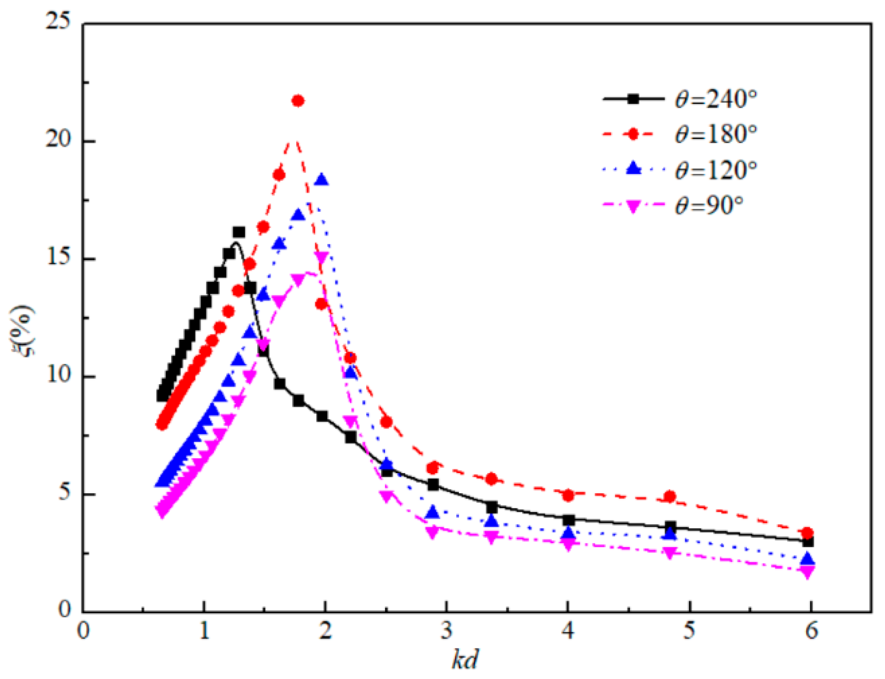
3.4. Effect of the Angle between the Baffle Wall
The baffle wall angle θ determines the shape and the volume of the air chamber. The larger the baffle wall angle, the larger the volume of air chamber, and the bigger span of the ring frames between the baffles (the frontal width of the chamber). In order to investigate the effect of the baffle angle on the power extraction efficiency of the OWC device, the relative diameter of the inner and outer cylinders D1/D2, the height of the inlet s/h and the incident wave height H are set constant. Figure 11 shows the conversion efficiency of the device against different kd with four baffle angles, i.e., θ = 240°, θ = 180°, θ = 120°, and θ = 90°. It can be observed that the conversion efficiency ξ increases with the increasing baffle angle for θ = 90–180° and reaches a maximum value at θ = 180°. This is because with the increase of the baffle wall angle, the frontal width of the chamber and the volume size are getting larger, which results in a large number of waves flow into the air chamber for power extraction. Compared with the condition of baffle angle θ = 240°, the corresponding kd for the peak value of the conversion efficiency with θ = 90–180° are relatively large and increases with the decreasing baffle angle θ. However, when the angle θ is greater than 180°, the maximal conversion efficiency ξ decreases, which may be the cause of the reflection of the waves acting on the baffle wall of the chamber. For the baffle angle θ less than 180°, the direction of wave reflections point into the inside of the chamber, which can drive up the wave surface in the air chamber, whilst for the baffle angle larger than 180°, the propagation of the reflected waves diffuse to the outside of the chamber so that the water heave motions in the chamber weakened and the conversion efficiency of the wave energy decreased.
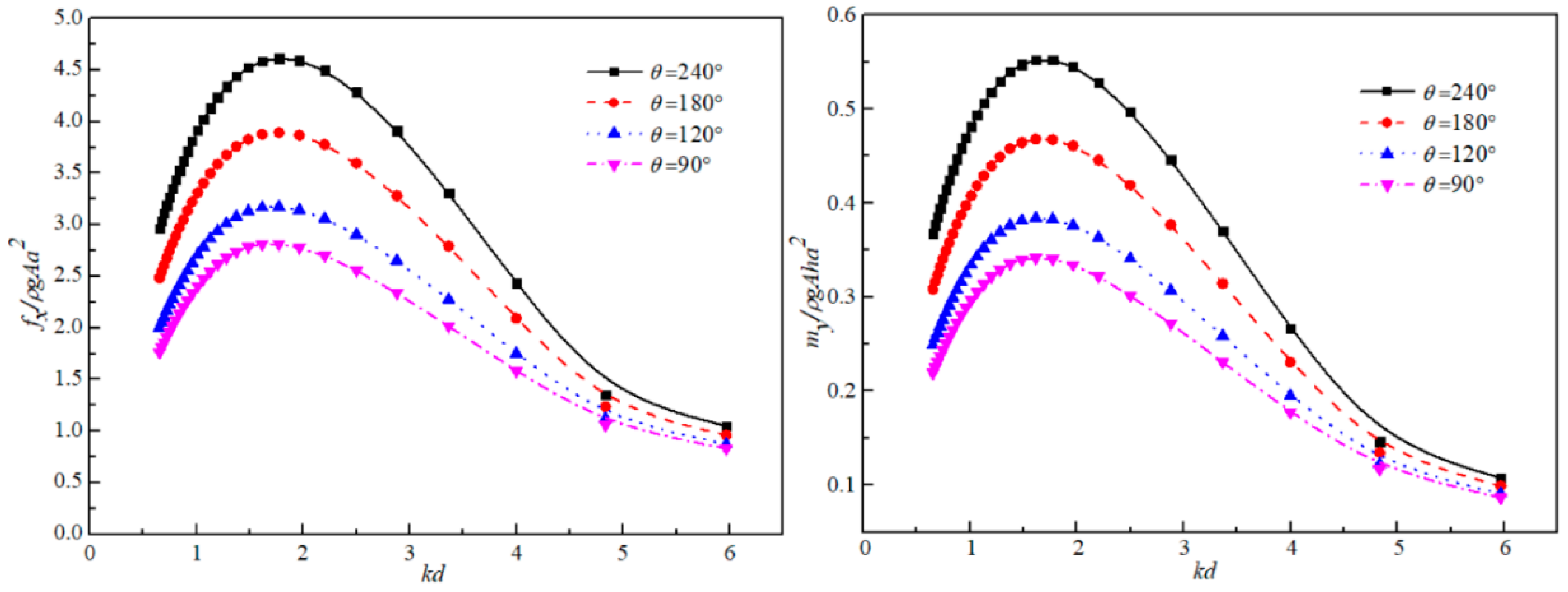
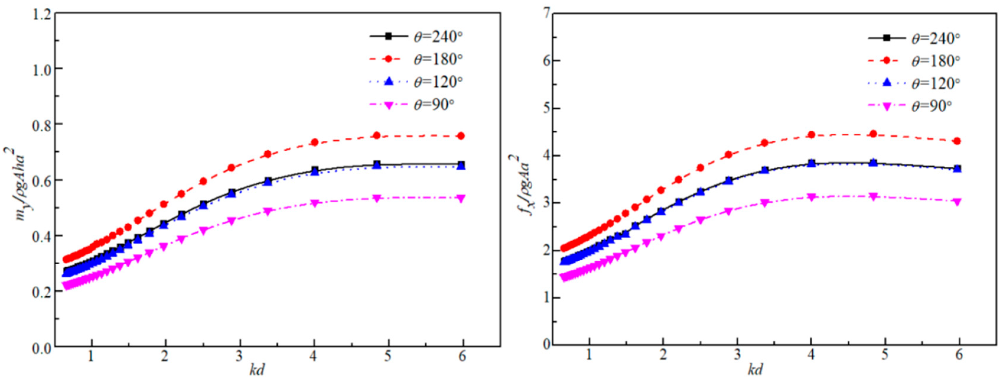
Further, the effect of the baffle angle θ on the hydrodynamic loads of the outer and inner cylinders against different kd are plotted in Figure 12 and Figure 13, respectively. It also can be observed in Figure 12 that the horizontal wave force fx and the bending moment my increase with the increment of the baffle wall angle, and the hydrodynamic loads of the device have a similar trend with the increasing wave number kd. The largest difference of the wave force and the bending moment with four baffle angle θ = 240°, θ = 180°, θ = 120°, and θ = 90° occur at kd = 1.77 and kd = 1.61, respectively. In the high-frequency zone, the hydrodynamic load difference among the considered four cases decreased with the increasing kd. Finally, the values of wave force fx and the bending moment my with different baffle angles are getting close to each other for larger wave number kd. In Figure 13, both the wave force and the wave moment have an increasing trend with the increase of kd. The results of the force and the moment against different wave number kd for θ = 240° and 120° are similar. And the force and moment for θ = 180° are the largest, which may be due to the resonant mode in the air chamber. On the other hand, for the inner cylinder, there is a different trend of the wave force and the bending moment acting on the outer cylinder. This may be the cause of the seriously oscillatory heave motion of the waves in the inner air chamber, which increases the power extraction but decrease the horizontal wave force and the bending moment on the inner cylinder.
3.5. Comparison of the Geometry Parameters
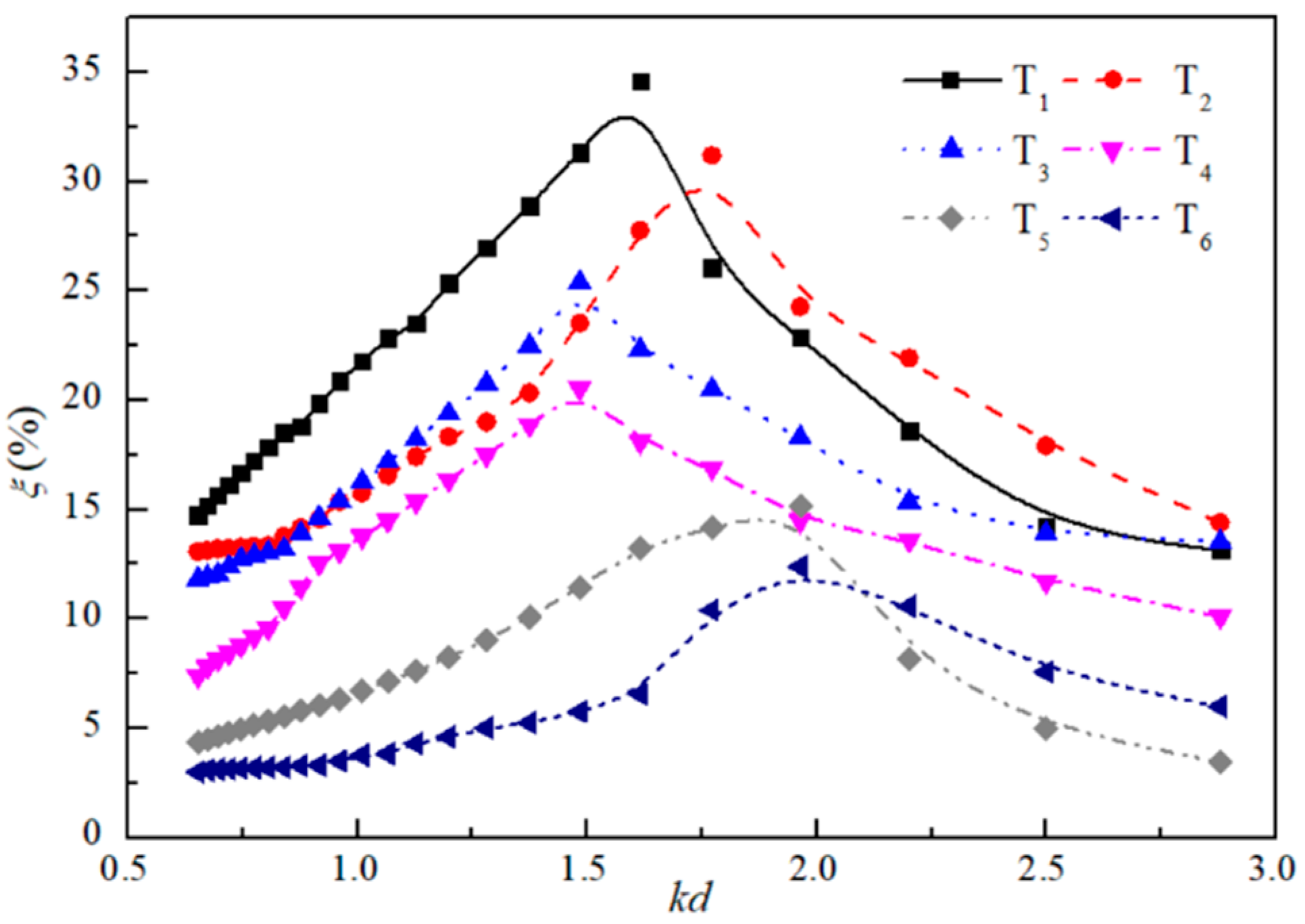
In order to improve the power extraction capacity of the OWC device, the geometry properties of the structure are compared for the optimization in this section. Six typical cases are chosen to calculate the wave conversion efficiency of the device in the analytical model covering the range of θ = 90–240° and D1/D2 = 0.2–0.75. The chamber inlet height and the incident wave height are set as constant s/h = 0.3 and H/d = 0.2, respectively. Figure 14 presents the energy conversion efficiency of the OWC device with six typical cases, i.e., T1(θ = 180°, D1/D2 = 0.4), T2(θ = 160°, D1/D2 = 0.45), T3(θ = 200°, D1/D2 = 0.35), T4(θ = 240°, D1/D2 = 0.2), T5(θ = 90°, D1/D2 = 0.7) and T6(θ = 90°, D1/D2 = 0.75). It can be seen that the maximum conversion efficiency occurs at the geometric parameter condition of D1/D2 = 0.4 and θ = 180° (Case T1), and conversely, the lowest conversion efficiency is Case T6, and for Cases T2-T5, the wave energy conversion efficiency of the OWC decreased in order. This illustrates that compared with the factor of baffle angle θ, the relative diameter ratio of the dual cylinders plays a dominant role in improving the power extraction capacity of the OWC. It also can be observed that the corresponding kd with the optimal conversion efficiency ξ for Case T6 is the largest, followed by the Cases of T5, T2, T1, T3 and T4, which rank with the same increasing sequence of the baffle angle. It demonstrates that the proposed OWC device has better absorbability for longer waves with larger baffle angle, and better absorption and conversion efficiency for shorter waves under smaller baffle angle conditions. In other words, the angle of the baffle wall in the chamber has a significant role to play in possessing better efficiency for the specific wave excitation periods. Therefore, the condition of Case T1 is recommended as the optimal geometry parameters for this proposed OWC device to possess a better capacity of the wave power extraction.
4. Conclusions
In this paper, a dual-cylindrical OWC wave energy converter integrated into a fixed caisson breakwater was investigated using analytical solutions based on the linear potential flow theory. The hydrodynamic performance and the conversion efficiency of the OWC were evaluated in the analytical model, and the effects of the OWC geometry characteristics and the wave motion inside the chamber were discussed for different wave conditions. Based on the analytical results, the following conclusions were drawn.
- The water surface elevation inside the chamber increases with the increasing wave period until it reaches a local maximum at a certain period (i.e., T = 0.85 s in the current study) and then starts to decrease.
- The conversion efficiency of the OWC device for different relative diameters and the baffle wall angles increased with the increasing wave number kd in the low-frequency zone. The corresponding kd for the optimal conversion efficiency of the OWC shifts towards the shorter period region with the increase of the relative diameter D1/D2.
- Given the same wave and geometry condition, the optimal conversion efficiency occurs when the relative cylindrical diameter D1/D2 is 0.4 and the baffle wall angle is 180°. It is hence concluded that the theoretical optimal geometry parameters as D1/D2 = 0.4 and θ = 180° are recommended for a better capacity of wave power extraction.
- The wave loads of the whole OWC go up with the increase of the wave number and then shows a fast decreasing trend in high-frequency regions.
- Compared with baffle-wall angle θ, the diameter ratio D1/D2 of the dual cylinders plays a dominant role in increasing the wave energy conversion efficiency. While for a specific incident wave period, the power extraction capacity of the OWC mainly determined by the angle of the baffle wall in the chamber.
Overall, the analytical results presented in this paper provided comprehensive and fast direct insight into the engineering aspects of the proposed OWC-WEC device for structure design and its geometry parameter optimization during operation on site. In the next stage, further studies on dual-chamber OWC models are recommended to improve the power extraction capacity of the device, and a series of experiments and numerical modeling will be conducted based on the present analytical solutions.
Author Contributions
C.W., C.Y., Q.F., Z.Y. and J.G. drafted the work, made substantial contributions to the design of the work, and made the final approval of the version to be published. C.W. and C.Y. derived the analytical model. C.W. conducted all the calculations. C.Y. and Y.W. reviewed the paper and contributed to the parametric analysis. All authors have read and agreed to the published version of the manuscript.
Funding
This research was funded by National Key R&D Program of China (Grant No.:2018YFB1501901) and the National Science Foundation of China (Grant Nos. 51808172 and 11272079).
Conflicts of Interest
The authors declare no conflict of interest.
References
- Doyle, S.; Aggidis, G.A. Development of multi-oscillating water columns as wave energy converters. Renew. Sustain. Energy Rev. 2019, 107, 75–86. [Google Scholar] [CrossRef] [Green Version]
- Shalby, M.; Dorrell, D.G.; Walker, P. Multi-chamber oscillating water column wave energy converters and air turbines: A review. Energy Res. 2019, 43, 681–696. [Google Scholar] [CrossRef]
- Deng, Z.; Huang, Z.; Law, A.W. Wave power extraction by an axisymmetric oscillating-water-column converter supported by a coaxial tube-sector-shaped structure. Appl. Ocean Res. 2013, 42, 114–123. [Google Scholar] [CrossRef]
- Huang, Y.; Shi, H.; Liu, D.; Liu, Z. Study on the breakwater caisson as oscillating water column facility. J. Ocean Univ. China 2010, 9, 244–250. [Google Scholar] [CrossRef]
- Graw, K.U. Wave energy breakwaters-a device comparison. In Proceedings of the Conference in Ocean Engineering, Madras, India, 17–20 December 1996. [Google Scholar]
- Suzuki, M.; Arakawa, C.; Takahashi, S. Performance of wave power generating system installed in breakwater at Sakata port in Japan. In Proceedings of the Fourteenth International Offshore and Polar Engineering Conference, Toulon, France, 23–28 May 2004. [Google Scholar]
- Healt, T.; Whittaker, T.; Boake, C. The design, construction and operation of the LIMPET wave energy converter (Islay, Scotland). In Proceedings of the 4th European Wave Energy Conference, Aalborg, Denmark, 4–6 December 2000. [Google Scholar]
- Falcão, A.F.O. The shoreline OWC wave power plant at the Azores. In Proceedings of the 4th European Wave Energy Conference, Aalborg, Denmark, 4–6 December 2000. [Google Scholar]
- Henriques, J.; Portillo, J.; Sheng, W.; Gato, L.; Falcão, A. Dynamics and control of air turbines in oscillating-water-column wave energy converters: Analyses and case study. Renew. Sustain. Energy Rev. 2019, 112, 571–589. [Google Scholar] [CrossRef]
- Falcão, A.F.O.; Henriques, J.C.C. Oscillating-water-column wave energy converters and air turbines: A review. Renew. Energy 2016, 85, 1391–1424. [Google Scholar] [CrossRef]
- Boccotti, P. Caisson breakwaters embodying an OWC with a small opening—Part I: Theory. Ocean Eng. 2007, 34, 806–819. [Google Scholar] [CrossRef]
- Boccotti, P.; Filianoti, P.; Fiamma, V.; Arena, F. Caisson breakwaters embodying an OWC with a small opening—Part II: A small-scale field experiment. Ocean Eng. 2007, 34, 820–841. [Google Scholar] [CrossRef]
- Boccotti, P. Design of breakwater for conversion of wave energy into electrical energy. Ocean Eng. 2012, 51, 106–118. [Google Scholar] [CrossRef]
- Shi, H.; Yang, G.; Liu, Z. Study on New Caisson Breakwater as OWC; Periodical of Ocean University of China (Natural Science Edition): Qingdao, China, 2010; Volume 40, pp. 142–146. [Google Scholar]
- Boccottti, P. Comparison between a U-OWC and a conventional OWC. Ocean Eng. 2007, 34, 799–805. [Google Scholar] [CrossRef]
- Tanimoto, K.; Takahashi, S.; Kimura, K. Structures and hydraulic characteristics of breakwaters the state of the art of breakwater design in Japan. Rep. Port Harb. Res. Inst. 1987, 26, 11–55. [Google Scholar]
- Mavrakos, S.A.; Chatjigeorgiou, I.K.; Mazarakos, T.; Konispoliatis, D. Experimental and numerical inverstgation of the hydrodynamic loads and wave elevation on concentric vertical cylinders. In Proceedings of the HYDRALAB III Joint User Meeting, Hannover, Germany, 2–4 February 2010. [Google Scholar]
- Mazarakos, T.; Konispoliatis, D.; Katsaounis, G.; Polyzos, S.; Manolas, D.; Voutsinas, S.; Soukissian, T.; Mavrakos, S.A. Numerical and experimental studies of a multi-purpose floating TLP structure for combined wind and wave energy exploitation. Mediterr. Mar. Sci. 2019, 20, 745–763. [Google Scholar] [CrossRef] [Green Version]
- Deng, Z.; Huang, Z.; Law, A.W.K. Wave power extraction from a bottom-mounted oscillating water column converter with a V-shaped channel. Proc. R. Soc. A Math. Phys. Eng. Sci. 2014, 470, 20140074. [Google Scholar] [CrossRef] [Green Version]
- Chen, J.; Wang, Y.; Wang, G.; Cai, L. Wave energy conversion efficiency of the dual cylindrical caisson breakwaters embodying an OWC with a semi-arc inlet on outer wall. Struct. Saf. Reliab. 2017. [Google Scholar] [CrossRef]
- Fleming, A.; Penesis, I.; Macfarlane, G.; Bose, N.; Denniss, T. Energy balance analysis for an oscillating water column wave energy converter. Ocean Eng. 2012, 54, 26–33. [Google Scholar] [CrossRef]
- Chen, F. Experimental study on conversion efficiency of dual-cylindrical OWC device. China Water Transp. 2016, 16, 288–292. [Google Scholar]
- Forestier, J.M.; Holmes, B.; Barrett, S.; Lewis, A.W. Value and validation of small scale physical model tests of floating wave energy converters. In Proceedings of the 7th European Wave and Tidal Energy Conference, Porto, Portugal, 11–13 September 2007. [Google Scholar]
- MacCamy, R.C.; Fuchs, R.A. Wave Forces on Plies: A Diffraction Theory; US Army Coastal Engineering Research Center: Vicksburg, MS, USA, 1954. [Google Scholar]
Figure 1.
Concept of the dual-cylindrical oscillating water column (OWC) wave energy converter.

Figure 2.
Schematic of the proposed OWC wave energy converter foundation.

Figure 3.
Comparisons of the wave force and wave moment between the present model and MacCamy’s results.
Figure 3.
Comparisons of the wave force and wave moment between the present model and MacCamy’s results.

Figure 4.
Comparison of the wave energy conversion efficiency ξ between dual-cylinder type OWC and hollow-cylindrical OWC.
Figure 4.
Comparison of the wave energy conversion efficiency ξ between dual-cylinder type OWC and hollow-cylindrical OWC.

Figure 5.
Comparison of the conversion efficiency ξ with different Ha/H between the present model and experimental data.
Figure 5.
Comparison of the conversion efficiency ξ with different Ha/H between the present model and experimental data.

Figure 6.
Sketch of the layout of semi-arc air chamber with four selected points A–D.

Figure 7.
Time series of wave free-surface elevation at four positions in the chamber at (a) C1, (b) C2, and (c) C3 conditions.
Figure 7.
Time series of wave free-surface elevation at four positions in the chamber at (a) C1, (b) C2, and (c) C3 conditions.

Figure 8.
Variations of dimensionless water surface amplitude with different incident wave heights.

Figure 9.
Effects of cylinder diameter D1/D2 on power extraction efficiency with different kd.

Figure 10.
Distribution of wave force and wave moment on the outer cylinder with different D1/D2.

Figure 11.
Distribution of conversion efficiency for different baffle wall angle θ.

Figure 12.
Variation of the wave force and the bending moment on the outer cylinder with different baffle wall angles.
Figure 12.
Variation of the wave force and the bending moment on the outer cylinder with different baffle wall angles.

Figure 13.
Variation of the wave force and the bending moment on the inner cylinder with different baffle wall angles.
Figure 13.
Variation of the wave force and the bending moment on the inner cylinder with different baffle wall angles.

Figure 14.
Variation and range extended comparison of the OWC conversion efficiency for typical cases.
Figure 14.
Variation and range extended comparison of the OWC conversion efficiency for typical cases.


Table 1.
Outline of dimensional variables.
| Dimensional Variable | Physical Unit |
|---|---|
| Wave amplitude, A | m |
| Water depth, d | m |
| Diameter of the outer cylinder, D1 | mm |
| Diameter of the inner cylinder, D2 | mm |
| Gravitational acceleration, g | m∙s−2 |
| Height of the cylinder, h | mm |
| Incident wave height, H | m |
| Incident wave number, k | -- |
| Air pressure, P0 | kPa |
| Height of the opening, s | mm |
| Time, t | s |
| Velocity potential, Φ | m∙s−1 |
| Wave period, T | s |
| Angular frequency, ω | rad∙s−1 |
| Water density, ρ | kg∙m−3 |
| The angle between partition walls, θ | -- |
| Power extraction efficiency, ξ | % |
© 2020 by the authors. Licensee MDPI, Basel, Switzerland. This article is an open access article distributed under the terms and conditions of the Creative Commons Attribution (CC BY) license (http://creativecommons.org/licenses/by/4.0/).
Share and Cite
MDPI and ACS Style
Wan, C.; Yang, C.; Fang, Q.; You, Z.; Geng, J.; Wang, Y. Hydrodynamic Investigation of a Dual-Cylindrical OWC Wave Energy Converter Integrated into a Fixed Caisson Breakwater. Energies 2020, 13, 896. https://doi.org/10.3390/en13040896
AMA Style
Wan C, Yang C, Fang Q, You Z, Geng J, Wang Y. Hydrodynamic Investigation of a Dual-Cylindrical OWC Wave Energy Converter Integrated into a Fixed Caisson Breakwater. Energies. 2020; 13(4):896. https://doi.org/10.3390/en13040896
Chicago/Turabian StyleWan, Chang, Can Yang, Qinghe Fang, Zaijin You, Jing Geng, and Yongxue Wang. 2020. "Hydrodynamic Investigation of a Dual-Cylindrical OWC Wave Energy Converter Integrated into a Fixed Caisson Breakwater" Energies 13, no. 4: 896. https://doi.org/10.3390/en13040896
Note that from the first issue of 2016, this journal uses article numbers instead of page numbers. See further details here.