Article

Convective Heat Transfer Enhancement through Laser-Etched Heat Sinks: Elliptic Scale-Roughened and Cones Patterns

1
Department of Energy, Politecnico di Torino, Corso Duca degli Abruzzi 24, 10129 Torino, Italy
2
Department of Applied Science and Technology, Politecnico di Torino, Corso Duca degli Abruzzi 24, 10129 Torino, Italy
*
Author to whom correspondence should be addressed.
Current address: DENSO Thermal Systems, Poirino (TO)-Italy.
These authors contributed equally to this work.
Energies 2020, 13(6), 1360; https://doi.org/10.3390/en13061360
Submission received: 7 February 2020 / Revised: 6 March 2020 / Accepted: 10 March 2020 / Published: 15 March 2020
(This article belongs to the Collection Advances in Heat Transfer Enhancement)

Abstract

:
The efficient dissipation of localized heat flux by convection is a key request in several engineering applications, especially electronic ones. The recent advancements in manufacturing processes are unlocking the design and industrialization of heat exchangers with unprecedented geometric characteristics and, thus, performance. In this work, laser etching manufacturing technique is employed to develop metal surfaces with designed microstructured surface patterns. Such precise control of the solid-air interface (artificial roughness) allows to manufacture metal heat sinks with enhanced thermal transmittance with respect to traditional flat surfaces. Here, the thermal performance of these laser-etched devices is experimentally assessed by means of a wind tunnel in a fully turbulent regime. At the highest Reynolds number tested in the experiments ( R e L 16 , 500 ), elliptic scale-roughened surfaces show thermal transmittances improved by up to 81% with respect to heat sinks with flat surface. At similar testing conditions, cones patterns provide an enhancement in Nusselt number and thermal transmittance of up to 102% and 357%, respectively. The latter results are correlated with the main geometric and thermal fluid dynamics descriptors of the convective heat transfer process in order to achieve a predictive model of their performance. The experimental evidence shown in this work may encourage and guide a broader use of micro-patterned surfaces for enhancing convective heat transfer in heat exchangers.

1. Introduction

The heat dissipation in electronic devices has substantial importance because it significantly affects performance, eventually leading to malfunctioning or failures if not correctly managed [1]. In fact, the operating temperature of electronic systems, which is usually regulated by proper cooling technologies, influences the length of their trouble-free operation and durability. Nowadays, electronic equipment such as microprocessors or batteries produce increasingly higher quantities of waste heat [2,3]. At the same time, the progressive reduction in size of electronic devices implies less space available for cooling purposes. While these factors indicate an improvement in electronics performance and usability, they have stimulated the investigation of more efficient heat dissipation technologies in miniaturized applications [4,5].
Heat sinks are devices allowing to transfer the heat generated by mechanical or electrical equipment to a fluid, e.g., gas or liquid coolants, thus managing to regulate their temperature at optimal levels [6]. Heat sinks are typically made of copper or aluminum and are designed to maximize the surface in contact with the cooling medium, aiming to optimize the heat exchange. These heat exchangers are widely used with high-performing microprocessors [7], high-power semiconductor devices (e.g., power transistors [8]), and optoelectronics (e.g., lasers and light emitting diodes [9]) to dissipate the heat generated during their operation.
Several coolants have been employed with heat sinks, namely gas [10], liquid [11,12], or two-phase [13,14] ones, as well as nanofluids [15,16]. Even if solutions with liquid and phase-change coolants have been proved to be very efficient, their use in commercial appliances widely spread on the market is limited by the cost and complexity. Instead, air-based cooling solutions are generally more suitable for everyday devices, thanks to their reliability and cheapness. Among this category, innovative configurations have been lately studied to enhance the heat transfer capability and include the use of unshrouded plate fins [10], pin fin arrays [17,18], ribs [19,20,21], dimples [22,23], carbon nanotubes structures [24], arrays of protrusions [25,26], Pitot tubes [27], innovative roughened surfaces [28,29], porous media [30,31], phase-change materials [32,33], or metal foams [34,35].
Recent innovations in the field of manufacturing are allowing the design of heat sinks with unprecedented geometries and surface features [36]. Heat sinks with enhanced thermal performance given by micro-protruded patterns and artificial roughness have been lately manufactured by direct metal laser sintering (DMLS). For example, we have experimentally demonstrated that both flat and finned heat sinks can be produced by DMLS with controllable surface roughness, and this leads to augmented convective heat transfer coefficients with respect to the typically smooth surfaces obtained by milling or extrusion processes [37,38]. In detail, DMLS technique allows to obtain an average surface roughness of up to 36 μ m (far superior to standard milling, i.e., 1 μ m), which provides an improvement in the convective heat transfer coefficient of up to 73% and 40% (compared to milled samples) for flat and finned heat sinks, respectively [37]. Laser etching is another promising manufacturing technique. In this process, a galvanometric head is used to precisely control the position of a laser beam, which focuses its radiation to a micro-sized spot. Thanks to this manufacturing technique, a broad variety of microstructured patterns can be engraved on metal surfaces at relatively low operating costs [39]. Laser etching has been previously employed to manufacture metal heat sinks with micro-fins characterized by lengths in the range 200–1100 μ m, which showed enhanced convective heat transfer coefficient with respect to smooth heat sinks [40].
The present work is focused on the experimental test and model prediction of the thermal transmittance of surface micro-patterned copper heat sinks manufactured by laser etching. Two sets of surface patterns are assessed following a proper design of experiments, namely elliptic scale roughened-surfaces (ESR) and cones ones, with different geometric characteristics. On the one side, while ESR samples have been object of some investigations in the recent literature [41,42] in the channel flow configuration, here, a flush-mounted configuration is studied experimentally for the first time. On the other side, to the best of our knowledge, heat sinks with cones microstructures on the surface have been first proposed in this work. The target is to evaluate whether and by how much the use of these designed micro-patterns increases the convective heat exchange through flush-mounted heat sinks and to correlate their thermal transmittance with the geometric and thermal fluid dynamics characteristics of the heat transfer process.

2. Materials and Methods

Smooth copper samples with 11.1 × 11.1 × 5 mm3 size and 11.1 × 11.1 mm2 heat transfer surface ( A n ) are engraved with microstructured patterns by laser etching. A diode-pumped solid-state (DPSS) laser system characterized by emission at 532 nm, 10 W power, 25 μ m spot size, and 3000 mm s−1 scan speed has been employed for the laser etching process by Microla Optoelectronics S.r.l. [40]. Short pulse duration (nanoseconds) are employed to achieve a good match between the desired geometric characteristics and the real sample.
The geometric design parameters of both ESR and cones patterns have been chosen according to a suitable design of experiment (DoE). In particular, the Taguchi method has been applied to reduce the number of tests at the minimum while obtaining the maximum information about the geometric factors of the patterns that affect the convective heat transfer process [43]. Hence, nine samples with ESR micro-patterns and nine with cones micro-patterns have been designed, manufactured, and tested. The convective heat transfer coefficient of each sample has been experimentally evaluated in the flush-mounted configuration in a calibrated wind tunnel.

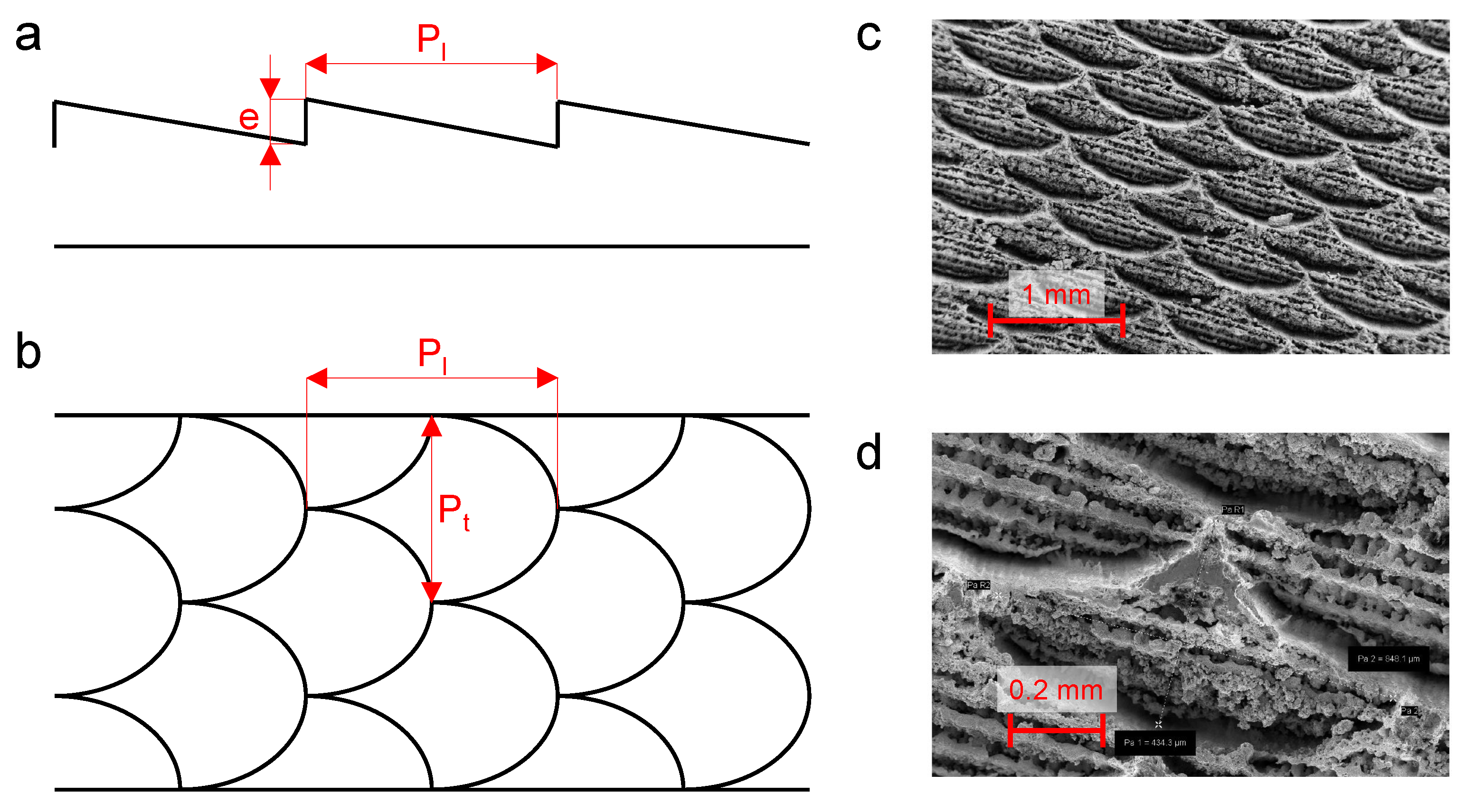
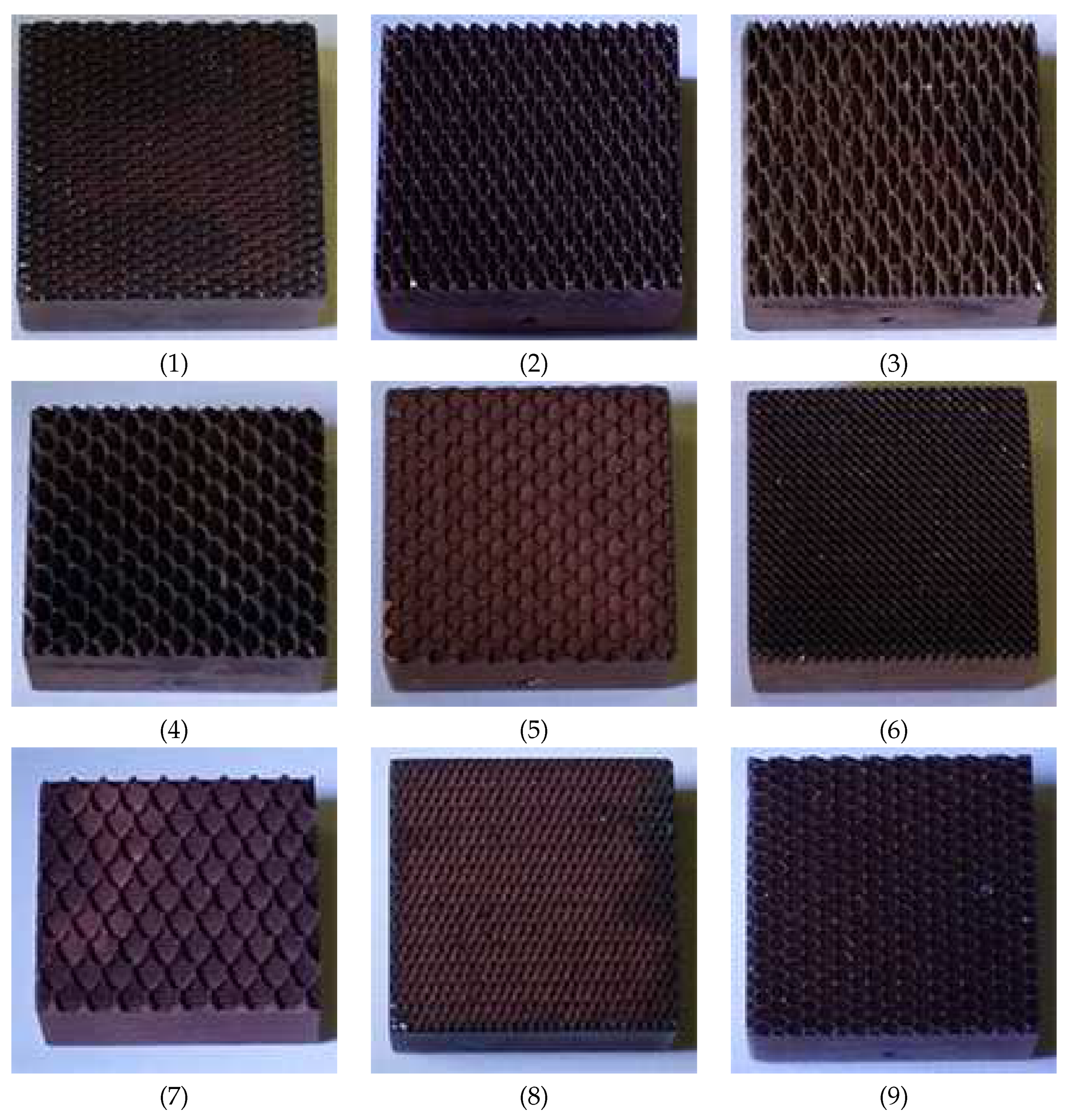
2.1. Elliptic Scale-Roughened Patterns
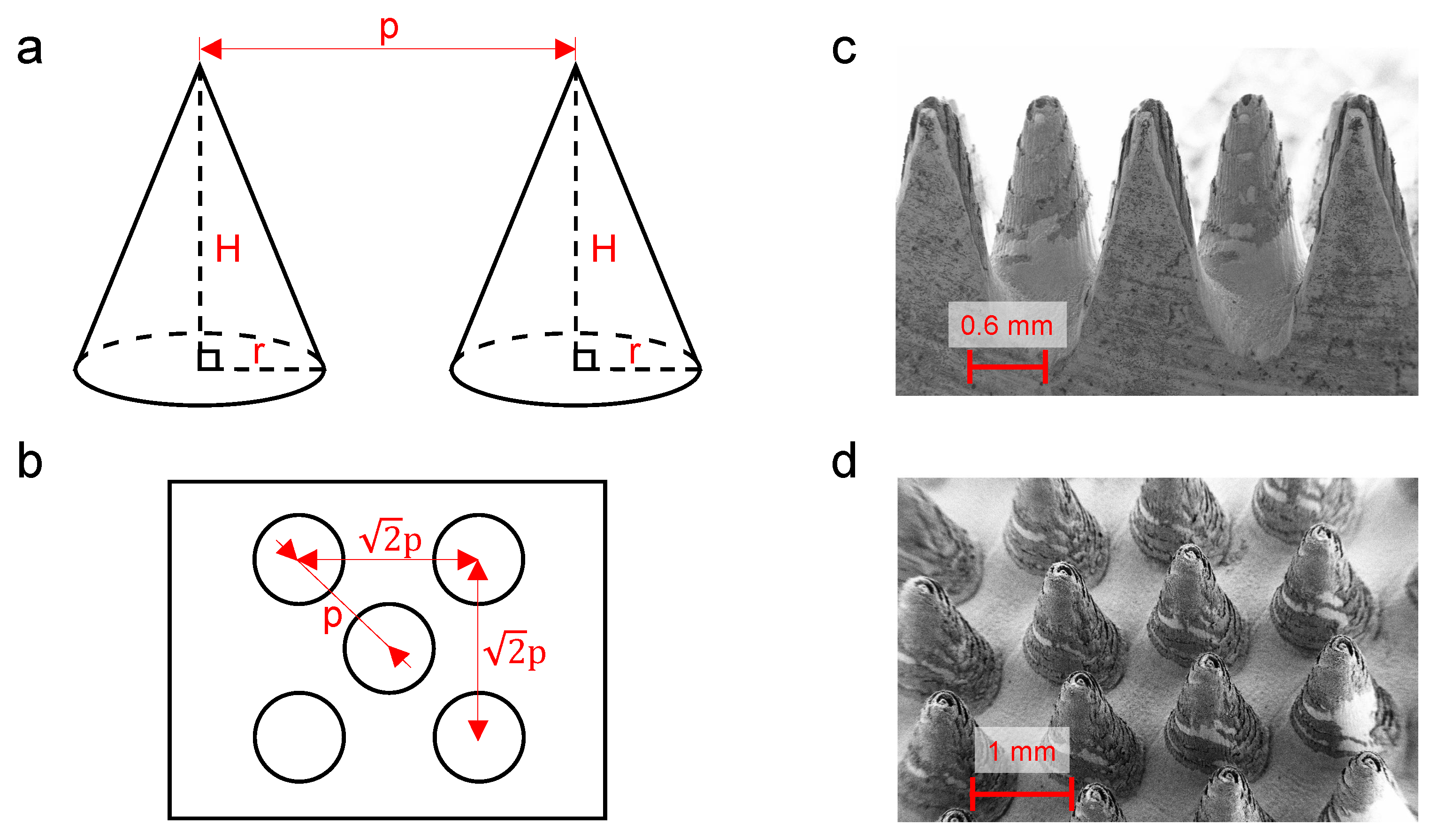
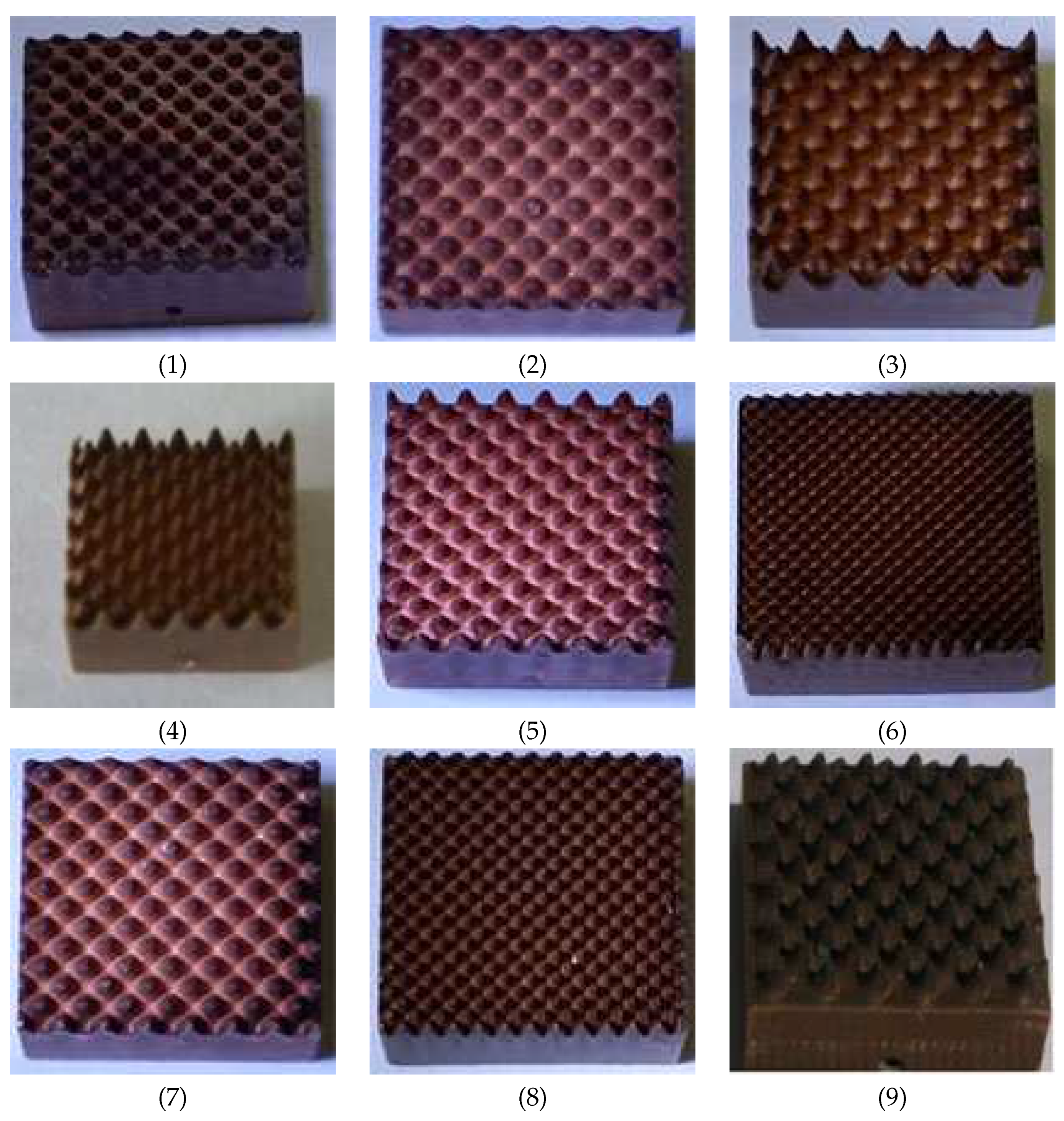
The general geometric configuration of the ESR (also known as shark skin-like) surface is depicted in Figure 1a,b. The design parameters of this pattern are the longitudinal ( P l ) and transverse ( P t ) axes of the ellipse and the maximum height of the scale (e). In Figure 1c,d, the geometric configuration of a representative ESR sample as captured by field emission scanning electron microscopy (FESEM) is reported (ZEISS SUPRA 40).
The Taguchi method [44] is employed for defining the most adequate set of geometric characteristics of the ESR patterned samples to be tested. To improve the generality of the analysis, the following three dimensionless parameters have been considered in the design of experiments: r p , the eccentricity of the ellipse; A / A n , the ratio between the heat transfer surface of the ESR patterned sample (A) and that of the smooth one ( A n ); and V / ( A Y 0 ) , the ratio between the volume of the specimen (V) and the product between the heat transfer surface and average viscous length ( Y 0 ) [45] for the tested flush-mounted configuration.
The ratio r p represents the eccentricity of the elliptic cell of the shark-like pattern, namely
r p = P l P t .
Low values of r p correspond to elongated scale configurations, and high values correspond to squeezed ones.
The ratio A / A n quantifies the heat transfer surface augmentation provided by the laser etching process compared to the initial smooth surface of the sample, and it can be calculated from the geometry of the pattern as
A A n = 1 + π 3 8 P t + P l P t P l 1 4 P t P l e ,
where A / A n 1 .
The third dimensionless parameter V / ( A Y 0 ) , instead, can be geometrically computed as
V A Y 0 = 3 4 π 8 e 1 + π e 3 8 P t + P l P t P l 1 4 P t P l Y 0
for the considered ESR patterns. Notice that V / A indicates the amount of material used for the sample realization with respect to the actual area available for heat dissipation in the flush-mounted configuration: low values of this ratio indicate a small amount of material for the specimen realization, thus leading to lower costs. The average viscous length ( Y 0 ) can be calculated as the mean value of the viscous length ( y 0 ) over the range of fluid flows assessed in the experiments [46], that is
Y 0 = 1 R e D , m a x R e D , m i n R e D , m i n R e D , m a x y 0 ( R e D ) d R e D ,
where
R e D = u D ν ,
where D is the hydraulic diameter of the wind tunnel [47] and ν is the kinematic viscosity of the fluid.
Following the Taguchi method (3 parameters, 3 levels, and 9 tests), we define an adequate design of experiments by considering the possible levels of r p , A / A n , and V / ( A Y 0 ) reported in Table 1. As a result, Table 2 shows the full experimental configuration for the nine manufactured samples, which are also depicted in Figure 2.

2.2. Cones Patterns

The general geometric configuration of cones patterned surface is depicted in Figure 3a,b. The design parameters of this pattern are the height (H) and radius (r) of the cones and the pitch (p). In Figure 3c,d, the geometric configuration of a representative surface covered by cones as captured by FESEM is reported.
Again, the generality of the analysis is pursued by introducing three dimensionless parameters of the cones patterned samples: λ p (the plane solidity), A / A n , and V / ( A Y 0 ).
The plane solidity quantifies the density of the cones with respect to the available surface, being defined as the fraction of the smooth surface area covered by protrusions:
λ p = π r 2 3 p 2 .
where λ p is expected to strongly influence the convective heat transfer mechanism: low values should lead to enhanced heat transfer due to perturbation of the boundary layer, whereas high values should cause stagnation phenomena, thus inducing a reduction in the convection [48].
The other parameters are defined similarly to what was previously discussed regarding the ESR patterns. In this case, the parameter A / A n can be computed from the geometry of the pattern as
A A n = π r r 2 + H 2 + p 2 π r 2 p 2 ,
while the parameter V / ( A Y 0 ) as
V A Y 0 = π r 2 H 3 π r r 2 + H 2 + 3 p 2 3 π r 2 Y 0 .
Following the Taguchi method (3 parameters, 3 levels, and 9 tests), we define an adequate design of experiments by considering the possible levels of λ p , A / A n , and V / ( A Y 0 ) reported in Table 3. As a result, Table 4 and Figure 4 show the actual configuration of the nine manufactured samples.

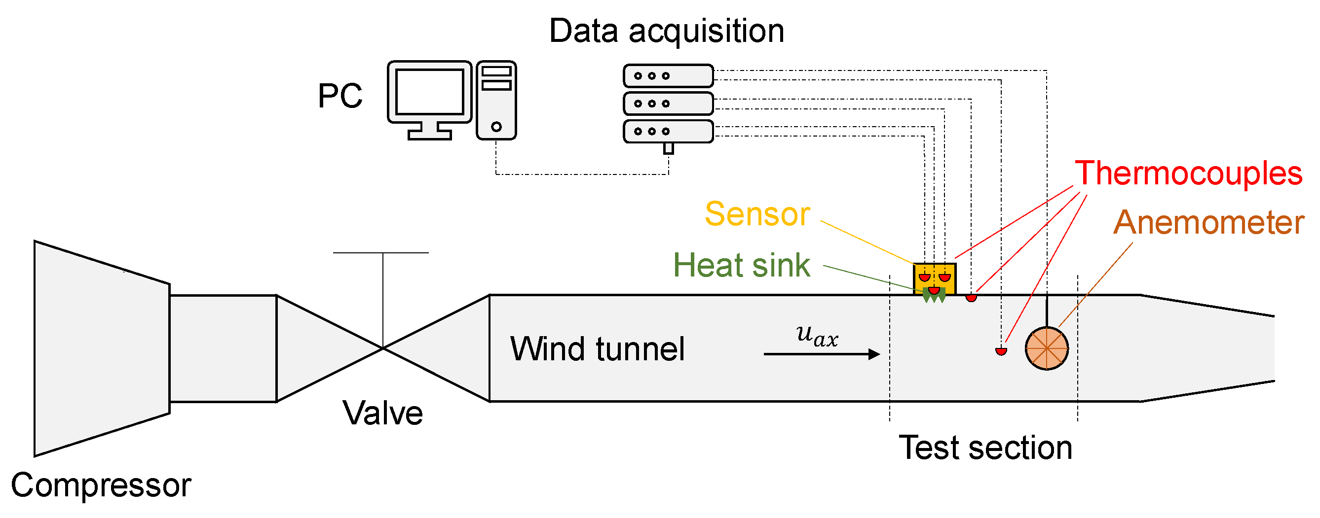
2.3. Experimental Setup

The convective heat transfer coefficient (h) of the flush-mounted ESR and cones patterned samples has been assessed in a wind tunnel calibrated in previous works [38,47] (see the schematic in Figure 5). The wind tunnel facility includes a 5 m long, 228 mm high, and 158 mm wide channel entirely made of steel. The length of the channel is approximately equal to 26 hydraulic diameters, being D 187 mm.
The axial velocity of the air flow ( u a x ) is measured by a vane anemometer, which is installed right downstream the tested sample. The convective heat transfer coefficient is measured thanks to a sensor based on the concept of thermal guard, of which the complete description is given in Reference [47]. This sensor is composed by a copper box of 20.0 mm × 20.0 mm × 8.0 mm, named guard, with a squared and centered hole of 11.1 mm × 11.1 mm × 5.0 mm that accommodates the tested sample. The guard is maintained at the same temperature of the tested sample by a first controllable electrical heater. In this way, the heat—which is provided by a second controllable electrical heater placed on the back side of the sample—can only flow through the sample, therefore allowing a precise measure of the convective heat transfer coefficient. Alignment and mounting procedures of the sensor inside the wind tunnel are reported in Reference [38]. Five type K thermocouples monitor the temperatures in the test rig: two for the guard and one each for the sample, the inner wall of the wind tunnel and the air. The coefficient h can be finally computed from these measured temperatures following the protocol established in Reference [47].

3. Results

The thermal performance of the laser-etched heat sinks can be conveniently described as a function of the typical dimensionless numbers adopted for convective heat transfer.
The measured air velocity in the tunnel is employed to compute the Reynolds number R e D a x = u a x D / ν , with ν = 1.544 × 10 5 m2 s−1. Then, the Reynolds number based on the average air velocity is estimated as R e D = u D / ν = 0.694 ( R e D a x ) 1 . 0162 in the adopted test rig [47]. In case of flush-mounted heat sinks, the Reynolds number can be also referred to as the heated edge ( L = 20 mm, namely the heated edge of the guard) [46]. In the considered experimental conditions, first, R e L a x = u a x L / ν is computed, then, the Reynolds number referred to as the heated edge and average air velocity is estimated as R e L = u L / ν = 0.669 ( R e L a x ) 1 . 0162 [47]. Experiments have been carried out with R e L in a range approximately equal to 3500–16,500, with an average viscous length equal to Y 0 = 50.3 μ m (see Reference [46] for calculation details).
The experimental thermal performance of the heat sinks are expressed here in terms of N u L / P r 0 . 33 , T r = h A (thermal transmittance), and T r / V . In detail, N u L / P r 0 . 33 is the ratio between the dimensionless Nusselt ( N u L = h L / λ ) and Prandtl ( P r = ν / α ) numbers, where λ = 2.622 × 10 2 W m−1 K−1 is the thermal conductivity of air and α = 2.224 × 10 5 m2 s−1 is its thermal diffusivity. The reported error bars of measures refer to both type A and type B uncertainties, calculated according to Reference [38] with significance level equal to 5 % .

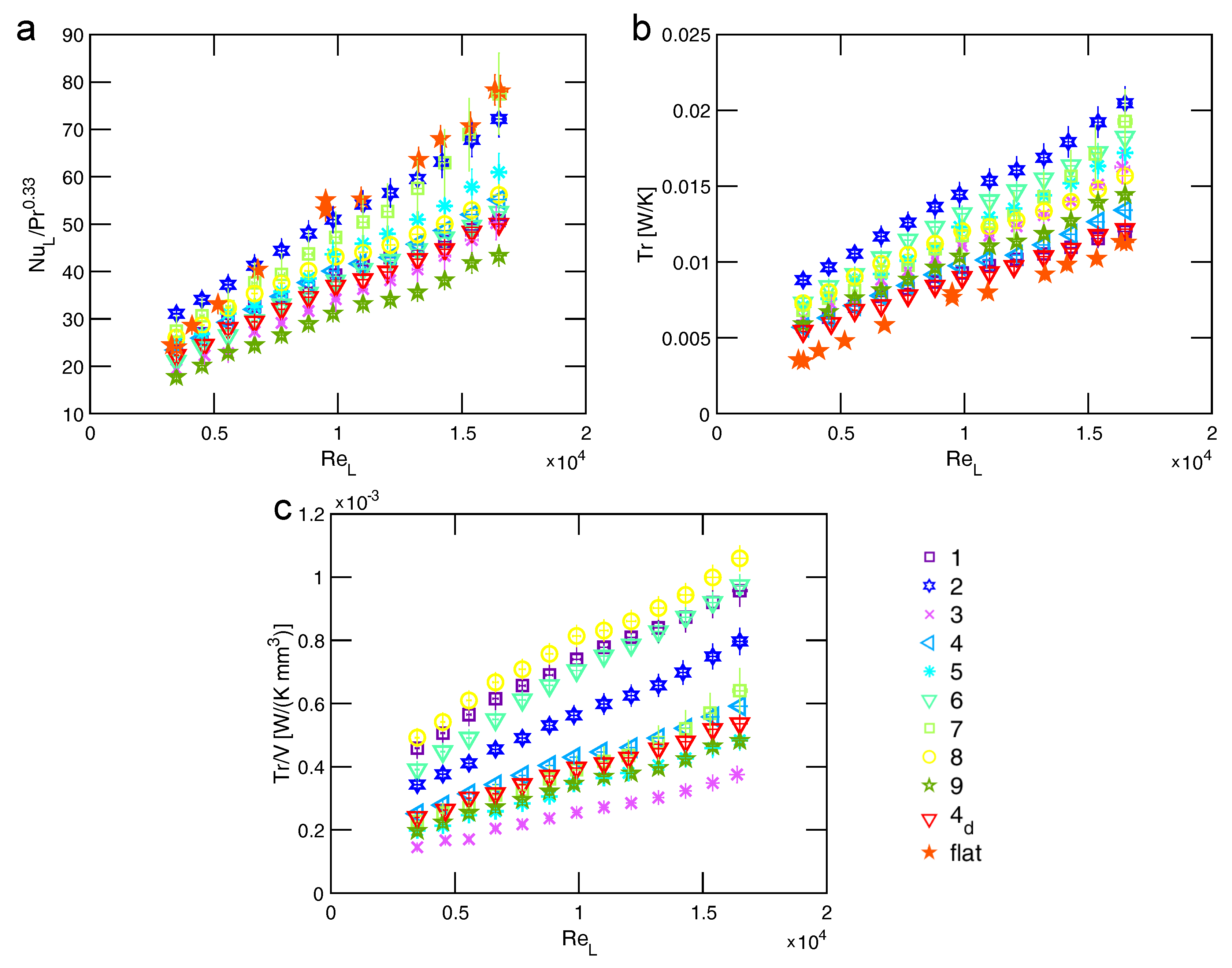
3.1. Elliptic Scale-Roughened Patterns
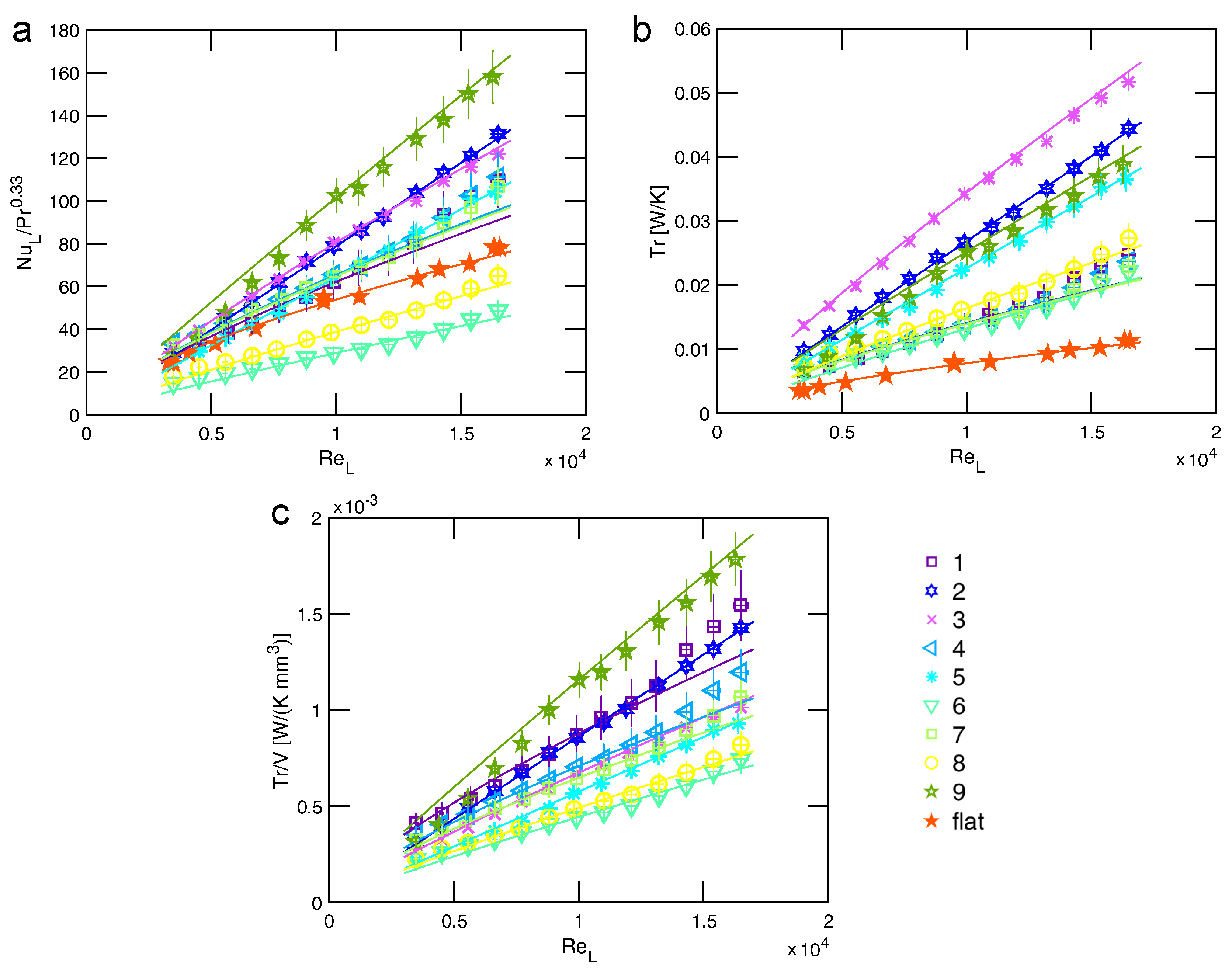
All elliptic scale-roughened samples have been tested with the air flowing along the forward direction, i.e., u a x directed from left to right in Figure 1a,b, since this orientation has previously demonstrated to achieve higher heat transfer rates [41]. Figure 6 shows the values obtained for N u L / P r 0.33 , T r , and T r / V at different Reynolds number. As expected, the thermal transmittance of the laser-etched samples is higher than the smooth one, with T r enhancements up to 81% for the best performing configuration (sample 2 at R e L = 16 , 500 ; see Figure 6b). However, the observed enhancement should be mainly ascribed to the larger heat transfer surface of laser-etched samples (A) with respect to the flat one ( A n ) and not to higher convective heat transfer coefficients.
In fact, as noticeable from Figure 6a, the ratio N u L / P r 0.33 and thus the Nusselt number of heat sinks with ESR patterns is predominantly lower with respect to the one of flat surface, especially at high R e L . On the one side, comparing the N u L / P r 0.33 results at a representative low value of R e L 3480 , the best performing elliptic scale-roughened heat sink is sample 2 (+29% with respect to the N u L / P r 0.33 of flat surface at similar testing conditions), while the worst one is sample 9 (−26%). On the other side, considering a representative high value of R e L 16 , 500 , the best performing elliptic scale-roughened heat sink is sample 7 (−1% with respect to the N u L / P r 0.33 of flat surface at similar testing conditions), while the worst one is sample 9 again (−44%). Therefore, some ESR micro-patterns seem to have a positive effect on the convective heat transfer process at lower R e L , whereas they all show progressively lower values of N u L than the flat surface ones with higher R e L .
It is also interesting to notice that sample 8 provides the best thermal performance per unit volume of employed material, as visible in Figure 6c. For the sake of completeness, sample 4 has been also tested with air flowing in the downward direction; however, Figure 6a,b confirms that better heat transfer performance can be obtained with the forward direction, as previously noticed in References [41,49].

3.2. Cones Patterns

Considering the samples with cones pattern, a significant heat transfer augmentation with respect to flat heat sinks is observed for all the Reynolds number analyzed, with up to 357% enhancement in terms of T r (see Figure 7b, sample 3 at R e L = 16 , 500 ). In this case, such improved heat transfer is due to both A / A n > 1 and higher h. In fact, most heat sinks with cones pattern (except samples 6 and 8) show increased values of N u L with respect to the flat surface for the whole range of considered Reynolds numbers. In detail, comparing the N u L / P r 0.33 results at a representative low value of R e L 3480 , the best performing cones pattern is sample 4 (+39% with respect to the N u L / P r 0.33 of flat surface at similar testing conditions), while the worst one is sample 6 (−39%). Instead, considering a representative high value of R e L 16 , 500 , the best performing cones patterned heat sink is sample 9 (+102% with respect to the N u L / P r 0.33 of flat surface at similar testing conditions), while the worst one is sample 6 again (−38%). Also with the cones pattern, broad variations of T r / V can be observed between the different geometric configurations (Figure 7c), being the sample 9 with the best compromise between heat transfer and volume augmentation.
These results seem to be comparable with those found for heat sinks with other micro-patterns on their surface. Considering, for instance, the heat sinks with diamond shaped micro-protruded patterns tested in Reference [46], a comparison can be made at R e L = 16 , 500 between the best performing samples of each pattern: T r equal to 0.052 W K−1 (cones) vs. 0.085 W K−1 (diamonds); N u L / P r 0.33 equal to 158 (cones) vs. 188 (diamonds); and T r / V equal to 1.78 × 10 3 W K−1 mm−3 (cones) vs. 1.35 W K−1 mm−3 (diamonds). These results highlight that, at least for R e L = 16 , 500 , diamond patterns lead to higher heat transfer enhancement with respect to cones ones whereas cones micro-protrusions show a higher value of T r / V with respect to diamond ones (see Figure 8 for a complete overview on the whole range of tested R e L ).

4. Discussion

The experimental characterization of the laser-etched surfaces highlights that both ESR and cones patterns enhance the thermal transmittance of flush-mounted heat sinks. However, while the heat transfer augmentation from ESR patterns is only due to the larger surface, cones patterns also improve the convection process per se, therefore performing better than ESR samples and similarly to diamonds ones [46]. In this section, the improved heat transfer performance of cones patterns are modeled by semi-empirical correlations and the underlying thermal fluid dynamics mechanisms are discussed.

4.1. Semi-Empirical Model of Thermal Transmittance

Following the methodology adopted in Reference [46], a model able to predict the thermal transmittance ( T r = h A ) of a generic heat sink with cones patterns has been developed. Considering the reference Reynolds number R e L , R = 10 , 000 , T r can be modeled as the product of two functions, namely
T r = g T r R .
In Equation (9), T r R is the thermal transmittance value at R e L , R , which is expected to depend on the parameters employed in the design of experiments λ p , A A n , V A Y 0 . On the other hand, g accounts for values of R e different from the reference one, and it is modeled as a function of R e L R e L , R and H Y 0 [46].
First, T r R can be expressed as T r R = T r R 0 + Δ T r R , with T r R 0 as the thermal transmittance of the heat sink with flat surface at the reference Reynolds number and Δ T r R as the enhancement provided by the laser etching process. This model of T r R can be also rewritten as
T r R = T r R 0 + V Δ T r R V ,
where Δ T r R V is correlated with the dimensionless quantities of the design of experiments as
Δ T r R V = c 1 λ p ^ + c 2 A A n ^ + c 3 V A Y 0 ^ + c 4 λ p ^ 2 + c 5 A A n ^ 2 + c 6 V A Y 0 ^ 2 + c 7 λ p ^ A A n ^ + c 8 λ p ^ V A Y 0 ^ + c 9 A A n ^ V A Y 0 ^ .
In Equation (11), the design parameters are normalized with respect to their average value, that is
λ p ^ = λ p λ p A v r , λ p A v r = 1 9 i = 1 9 λ p i A A n ^ = A A n A A n A v r , A A n A v r = 1 9 i = 1 9 A A n i V A Y 0 ^ = V A Y 0 V A Y 0 A v r , V A Y 0 A v r = 1 9 i = 1 9 V A Y 0 i
where i stands for the ith sample. The vector { C } = { c 1 , c 2 , c 3 , c 4 , c 5 , c 6 , c 7 , c 8 , c 9 } collects the coefficients of the semi-empirical model in Equation (11). The value of such coefficients can be optimized to best fit the experimental results in Figure 7, leading to c 1 = 2.822 × 10 3 , c 2 = 2.060 × 10 3 , c 3 = 2.379 × 10 3 , c 4 = 1.751 × 10 3 , c 5 = 0.915 × 10 3 , c 6 = 0.036 × 10 3 , c 7 = 0.100 × 10 3 , c 8 = 1.609 × 10 3 × 10 3 , and c 9 = 0.480 × 10 3 , all expressed in terms of W/(K mm3).
Second, the function g is modeled as
g = R e L R e L , R B .
Similarly to the previous investigations on diamond shaped micro-protruded patterns for heat sinks [46], Figure 9 shows that the exponent B in Equation (13) can be correlated with the height of the protrusions (H) and the average viscous length ( Y 0 ) as
B = d 1 H Y 0 d 2 exp d 3 H Y 0 + d 4 ,
with d 1 = 2.887 × 10 6 , d 2 = 4.804 , d 3 = 0.156 , and d 4 = 0.660 as best fitted coefficients.
The good agreement between the experimental (symbols) and model (lines) results reported in Figure 7 proves that the semi-empirical model in Equations (9)–(14) provide a good approximation of T r (and related h and N u L thermal properties) for the tested cones patterned heat sinks.

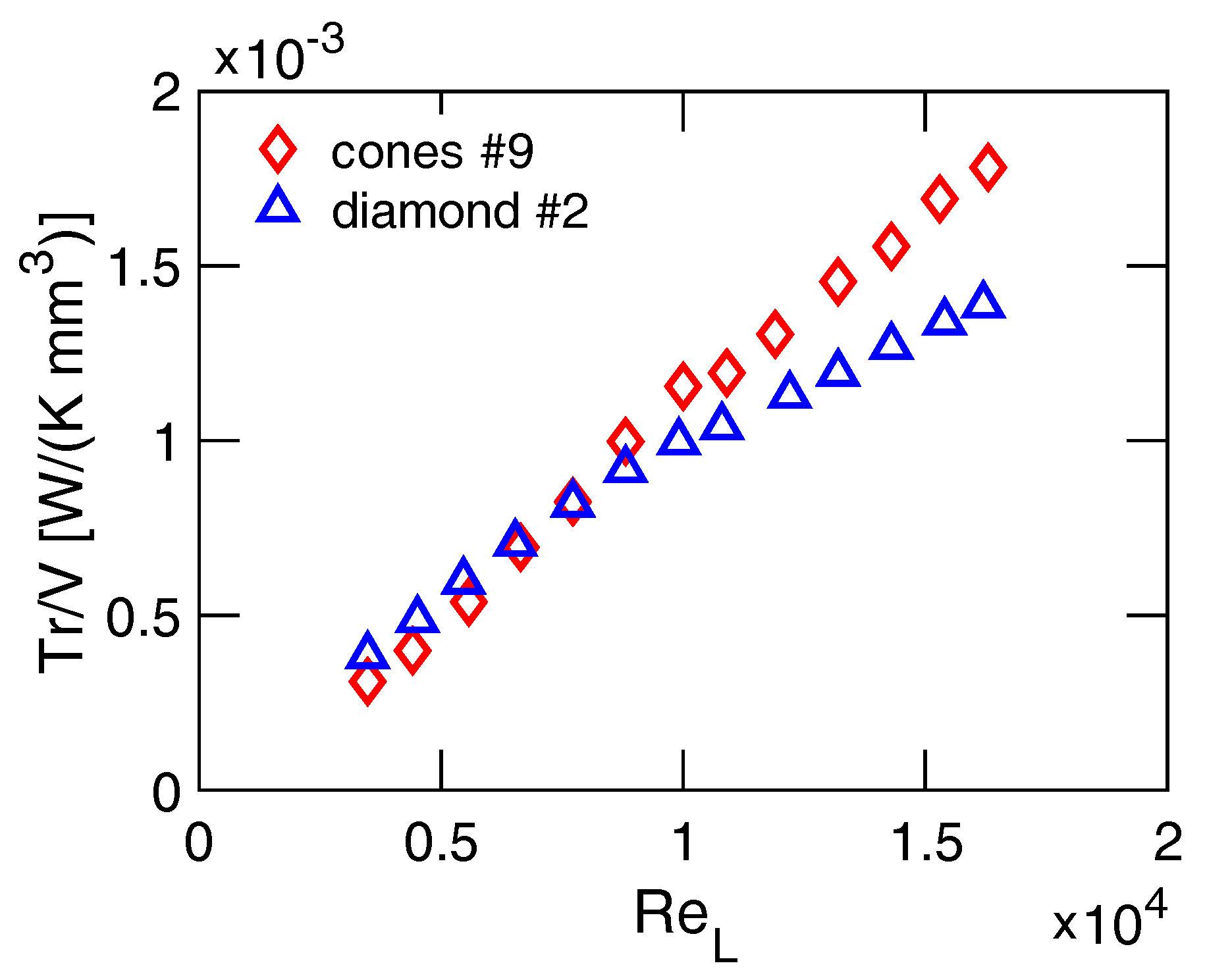
4.2. Thermal Fluid Dynamics Features of Cones Patterned Heat Sinks

Finally, the heat transfer performance observed for the cones patterned heat sinks are interpreted in light of their geometric features.
Experiments show that λ p is the geometric parameter of the cones pattern that most affects the convective heat transfer coefficient of the heat sink. Figure 10 shows that samples with low λ p are characterized by higher values of N u L / P r 0.33 , since sparse patterns can effectively interfere with the boundary layer while not causing air flow stagnation between the micro-protrusions. This appears to be a common feature for cones and diamonds patterns [46]. Instead, higher values of λ p , i.e., increasing pattern densities, cause air flow stagnation between the micro-protrusions and, thus, detrimental effects on convective heat transfer, and this eventually leads to N u L lower than the one of the reference flat heat sink (see samples 6 and 8 in Figure 7a).
Furthermore, results show that the height of protrusions (H) plays a key role in determining T r . As represented in Figure 7b, samples 2 and 3—which have the longest H among the considered cones patterned samples—show the highest values of thermal transmittance. This is due to both the enhanced heat transfer surface and to the fact that taller cones can better penetrate the boundary layer, therefore augmenting convection. On the other side, the highest values of T r / V are given by samples 1 and 9 (see Figure 7c), which have lower values of H: as a matter of fact, the ratio A / V of cones decreases with longer protrusions. H is also important to regulate how the fluid flow ( R e L ) affects T r . In fact, Figure 9 highlights that, similarly to diamonds patterns [46], an optimal value of H / Y 0 for the cones height can be found to maximize the enhancement of T r with R e L (see Equations (9) and (13)), according to a specific fluid flow regime ( R e L / R e L , R ). The optimal height of cones should be long enough to overcome the viscous sub-layer height of the air flow (that is, 5 y 0 [45]) but not too much to fall beyond the viscous wall region (that is, 50 y 0 [45]).

5. Conclusions

In this work, elliptic scale-roughened and cones patterned heat sinks manufactured by laser etching have been investigated to enhance convective heat transfer in applications requiring efficient heat dissipation, e.g., electronics. The effects of the geometric and thermal fluid dynamics parameters of the heat sinks on their thermal performance have been explored by experiments in a flush-mounted configuration, carried out according to the Taguchi method. A semi-empirical model able to correlate the thermal transmittance of the laser-etched heat sinks with the geometric features of micro-pattern and the fluid flow regime has been implemented and validated against the experiments. Results show that, at the highest Reynolds number tested in the experiments ( R e L 16 , 500 ), the elliptic scale-roughened patterns present up to a 81% enhancement in thermal transmittance with respect to the corresponding flat surface, mainly because of the larger heat transfer surface. Notably, at similar testing conditions, cones patterns show up to 357% augmentation of thermal transmittance with respect to the heat sink without micro-protrusions due to both higher heat transfer surface and improved Nusselt number (up to 102% increase). Experimental evidence also shows that the considered microstructured surface patterns are particularly effective in enhancing convective heat transfer at higher Reynolds numbers. By comparing these results with other laser-etched micro-protruded patterns available in the literature (e.g., diamond shaped ones [46]), cones patterns show relatively high values of thermal transmittance with respect to the volume of heat sink, at least for the upper range of Reynolds numbers tested in this study. Interestingly, the convective heat transfer coefficient enhancement of the laser-etched heat sinks with cones pattern is close to the one of flat surfaces manufactured by direct metal laser sintering with controllable artificial roughness [38]. In perspective, these results encourage and guide a broader adoption of designed micro-patterned surfaces obtained by innovative manufacturing techniques for enhancing convective heat transfer in compact heat exchangers.

Author Contributions

Conceptualization, L.V., P.A. and E.C.; methodology, L.V., P.A. and E.C.; validation, all authors; formal analysis, L.V., M.F., R.C. and L.B.; investigation, L.V. and F.C.; resources, L.V. and F.C.; data curation, L.V.; writing—original draft preparation, L.V. and R.C.; writing—review and editing, M.F. and L.B.; visualization, L.V. and M.F.; supervision, P.A., E.C. and L.S.; project administration, P.A.; funding acquisition, P.A. All authors have read and agreed to the published version of the manuscript.

Funding

This work was funded by the THERMALSKIN project (FIRB 2010, grant number RBFR10VZUG).

Acknowledgments

The authors acknowledge Enrico Armando Treggiari and Mattia Busatto for supporting the experimental activity. The authors are grateful with Microla Optoelectronics S.r.l. for producing the samples.

Conflicts of Interest

The authors declare no conflict of interest.

References

  1. Garimella, S.V.; Fleischer, A.S.; Murthy, J.Y.; Keshavarzi, A.; Prasher, R.; Patel, C.; Bhavnani, S.H.; Venkatasubramanian, R.; Mahajan, R.; Joshi, Y.; et al. Thermal Challenges in Next-Generation Electronic Systems. IEEE Trans. Components Packag. Technol. 2008, 31, 801–815. [Google Scholar] [CrossRef]
  2. Murshed, S.S.; De Castro, C.N. A critical review of traditional and emerging techniques and fluids for electronics cooling. Renew. Sustain. Energy Rev. 2017, 78, 821–833. [Google Scholar] [CrossRef]
  3. Lu, M.; Zhang, X.; Ji, J.; Xu, X.; Zhang, Y. Research progress on power battery cooling technology for electric vehicles. J. Energy Storage 2020, 27, 101155. [Google Scholar] [CrossRef]
  4. Garimella, S.V.; Persoons, T.; Weibel, J.; Yeh, L.T. Technological drivers in data centers and telecom systems: Multiscale thermal, electrical, and energy management. Appl. Energy 2013, 107, 66–80. [Google Scholar] [CrossRef] [Green Version]
  5. Bergamasco, L.; Alberghini, M.; Fasano, M.; Cardellini, A.; Chiavazzo, E.; Asinari, P. Mesoscopic moment equations for heat conduction: characteristic features and slow–fast mode decomposition. Entropy 2018, 20, 126. [Google Scholar] [CrossRef] [Green Version]
  6. Chu, R.C.; Simons, R.E.; Ellsworth, M.J.; Schmidt, R.R.; Cozzolino, V. Review of cooling technologies for computer products. IEEE Trans. Device Mater. Reliab. 2004, 4, 568–585. [Google Scholar] [CrossRef]
  7. Ding, B.; Zhang, Z.H.; Gong, L.; Xu, M.H.; Huang, Z.Q. A novel thermal management scheme for 3D-IC chips with multi-cores and high power density. Appl. Therm. Eng. 2019, 168, 114832. [Google Scholar] [CrossRef]
  8. Baumann, H.; Heinemeyer, P.; Staiger, W.; Topfer, M.; Unger, K.; Muller, D. Optimized cooling systems for high-power semiconductor devices. IEEE Trans. Ind. Electron. 2001, 48, 298–306. [Google Scholar] [CrossRef]
  9. Liu, L.; Zhang, G.; Yang, D.; Pan, K.; Zhong, H.; Hou, F. Thermal analysis and comparison of heat dissipation methods on high-power LEDs. In Proceedings of the 2010 11th International Conference on Electronic Packaging Technology & High Density Packaging, Xi’an, China, 16–19 August 2010; pp. 1366–1370. [Google Scholar]
  10. Ventola, L.; Curcuruto, G.; Fasano, M.; Fotia, S.; Pugliese, V.; Chiavazzo, E.; Asinari, P. Unshrouded Plate Fin Heat Sinks for Electronics Cooling: Validation of a Comprehensive Thermal Model and Cost Optimization in Semi-Active Configuration. Energies 2016, 9, 608. [Google Scholar] [CrossRef] [Green Version]
  11. Brighenti, F.; Kamaruzaman, N.; Brandner, J.J. Investigation of self-similar heat sinks for liquid cooled electronics. Appl. Therm. Eng. 2013, 59, 725–732. [Google Scholar] [CrossRef]
  12. Rubio-Jimenez, C.A.; Hernandez-Guerrero, A.; Cervantes, J.G.; Lorenzini-Gutierrez, D.; Gonzalez-Valle, C.U. CFD study of constructal microchannel networks for liquid-cooling of electronic devices. Appl. Therm. Eng. 2016, 95, 374–381. [Google Scholar] [CrossRef]
  13. Dobre, T.; Pârvulescu, O.C.; Stoica, A.; Iavorschi, G. Characterization of cooling systems based on heat pipe principle to control operation temperature of high-tech electronic components. Appl. Therm. Eng. 2010, 30, 2435–2441. [Google Scholar] [CrossRef] [Green Version]
  14. Ma, D.; Xia, G.; Zong, L.; Jia, Y.; Tang, Y.; Zhi, R. Experimental investigation of flow boiling heat transfer performance in zigzag microchannel heat sink for electronic cooling devices. Int. J. Therm. Sci. 2019, 145, 106003. [Google Scholar] [CrossRef]
  15. Buonomo, B.; Cirillo, L.; Manca, O.; Nardini, S.; Tamburrino, S. Numerical investigation on forced convection in rectangular cross section micro-channels with nanofluids. J. Physics Conf. Ser. 2017, 796, 012013. [Google Scholar] [CrossRef] [Green Version]
  16. Minea, A.A.; Manca, O. Field-synergy and figure-of-merit analysis of two oxide–water-based nanofluids’ flow in heated tubes. Heat Transf. Eng. 2017, 38, 909–918. [Google Scholar] [CrossRef]
  17. Deshmukh, P.; Warkhedkar, R. Thermal performance of elliptical pin fin heat sink under combined natural and forced convection. Exp. Therm. Fluid Sci. 2013, 50, 61–68. [Google Scholar] [CrossRef]
  18. Choudhary, V.; Kumar, M.; Patil, A.K. Experimental investigation of enhanced performance of pin fin heat sink with wings. Appl. Therm. Eng. 2019, 155, 546–562. [Google Scholar] [CrossRef]
  19. Cho, H.H.; Wu, S.J.; Kwon, H.J. Local Heat/Mass Transfer Measurements in a Rectangular Duct With Discrete Ribs. J. Turbomach. 1999, 122, 579–586. [Google Scholar] [CrossRef]
  20. Bahiraei, M.; Jamshidmofid, M.; Goodarzi, M. Efficacy of a hybrid nanofluid in a new microchannel heat sink equipped with both secondary channels and ribs. J. Mol. Liq. 2019, 273, 88–98. [Google Scholar] [CrossRef]
  21. Lopatin, A.A.; Nikolaeva, D.V. Influence of Some Geometrical Parameters of Split Ribs on the Heat Transfer under Free Convection. Russ. Aeronaut. 2019, 62, 254–258. [Google Scholar] [CrossRef]
  22. Elyyan, M.A.; Rozati, A.; Tafti, D.K. Investigation of dimpled fins for heat transfer enhancement in compact heat exchangers. Int. J. Heat Mass Transf. 2008, 51, 2950–2966. [Google Scholar] [CrossRef]
  23. Chen, Y.; Chew, Y.T.; Khoo, B.C. Enhancement of heat transfer in turbulent channel flow over dimpled surface. Int. J. Heat Mass Transf. 2012, 55, 8100–8121. [Google Scholar] [CrossRef]
  24. Pourdel, H.; Afrouzi, H.H.; Akbari, O.A.; Miansari, M.; Toghraie, D.; Marzban, A.; Koveiti, A. Numerical investigation of turbulent flow and heat transfer in flat tube. J. Therm. Anal. Calorim. 2019, 135, 3471–3483. [Google Scholar] [CrossRef]
  25. Mahmood, G.I.; Sabbagh, M.Z.; Ligrani, P.M. Heat Transfer in a Channel with Dimples and Protrusions on Opposite Walls. J. Thermophys. Heat Transf. 2001, 15, 275–283. [Google Scholar] [CrossRef]
  26. Gholami, M.; Nazari, M.R.; Talebi, M.H.; Pourfattah, F.; Akbari, O.A.; Toghraie, D. Natural convection heat transfer enhancement of different nanofluids by adding dimple fins on a vertical channel wall. Chin. J. Chem. Eng. 2019. [Google Scholar] [CrossRef]
  27. Fasano, M.; Ventola, L.; Calignano, F.; Manfredi, D.; Ambrosio, E.P.; Chiavazzo, E.; Asinari, P. Passive heat transfer enhancement by 3D printed Pitot tube based heat sink. Int. Commun. Heat Mass Transf. 2016, 74, 36–39. [Google Scholar] [CrossRef] [Green Version]
  28. Li, X.J.; Zhang, J.Z.; Tan, X.M. Effects of piezoelectric fan on overall performance of air-based micro pin-fin heat sink. Int. J. Therm. Sci. 2018, 126, 1–12. [Google Scholar] [CrossRef]
  29. Moradikazerouni, A.; Afrand, M.; Alsarraf, J.; Mahian, O.; Wongwises, S.; Tran, M.D. Comparison of the effect of five different entrance channel shapes of a micro-channel heat sink in forced convection with application to cooling a supercomputer circuit board. Appl. Therm. Eng. 2019, 150, 1078–1089. [Google Scholar] [CrossRef]
  30. Arasteh, H.; Mashayekhi, R.; Toghraie, D.; Karimipour, A.; Bahiraei, M.; Rahbari, A. Optimal arrangements of a heat sink partially filled with multilayered porous media employing hybrid nanofluid. J. Therm. Anal. Calorim. 2019, 137, 1045–1058. [Google Scholar] [CrossRef]
  31. Tseng, P.H.; Tsai, K.T.; Chen, A.L.; Wang, C.C. Performance of novel liquid-cooled porous heat sink via 3-D laser additive manufacturing. Int. J. Heat Mass Transf. 2019, 137, 558–564. [Google Scholar] [CrossRef]
  32. Al Siyabi, I.; Khanna, S.; Mallick, T.; Sundaram, S. Multiple Phase Change Material (PCM) Configuration for PCM-Based Heat Sinks—An Experimental Study. Energies 2018, 11, 1629. [Google Scholar] [CrossRef] [Green Version]
  33. Bondareva, N.S.; Buonomo, B.; Manca, O.; Sheremet, M.A. Heat transfer performance of the finned nano-enhanced phase change material system under the inclination influence. Int. J. Heat Mass Transf. 2019, 135, 1063–1072. [Google Scholar] [CrossRef]
  34. Mancin, S.; Zilio, C.; Diani, A.; Rossetto, L. Air forced convection through metal foams: Experimental results and modeling. Int. J. Heat Mass Transf. 2013, 62, 112–123. [Google Scholar] [CrossRef]
  35. Beer, M.; Rybár, R.; Kaľavský, M. Experimental heat transfer analysis of open cell hollow ligament metal foam at low Reynolds number. Measurement 2018, 133, 214–221. [Google Scholar] [CrossRef]
  36. Jafari, D.; Wits, W.W. The utilization of selective laser melting technology on heat transfer devices for thermal energy conversion applications: A review. Renew. Sustain. Energy Rev. 2018, 91, 420–442. [Google Scholar] [CrossRef]
  37. Ventola, L.; Chiavazzo, E.; Calignano, F.; Manfredi, D.; Asinari, P. Heat Transfer Enhancement by Finned Heat Sinks with Micro-structured Roughness. J. Phys. Conf. Ser. 2014, 494, 012009. [Google Scholar] [CrossRef]
  38. Ventola, L.; Robotti, F.; Dialameh, M.; Calignano, F.; Manfredi, D.; Chiavazzo, E.; Asinari, P. Rough surfaces with enhanced heat transfer for electronics cooling by direct metal laser sintering. Int. J. Heat Mass Transf. 2014, 75, 58–74. [Google Scholar] [CrossRef] [Green Version]
  39. Stephen, A.; Vollertsen, F. 3D Microstructuring of Mold Inserts by Laser-based Removal. In Microengineering of Metals and Ceramics: Part I: Design, Tooling and Injection Molding; WILEY-VCH: Hoboken, NJ, USA, 2005; pp. 131–159. [Google Scholar]
  40. Ventola, L.; Scaltrito, L.; Ferrero, S.; Maccioni, G.; Chiavazzo, E.; Asinari, P. Micro-structured rough surfaces by laser etching for heat transfer enhancement on flush mounted heat sinks. J. Physics Conf. Ser. 2014, 525, 012017. [Google Scholar] [CrossRef] [Green Version]
  41. Zhou, F.; Catton, I. A Numerical Investigation of Turbulent Flow and Heat Transfer in Rectangular Channels With Elliptic Scale-Roughened Walls. J. Heat Transf. 2013, 135, 081901. [Google Scholar] [CrossRef]
  42. Zhou, F.; Catton, I. Obtaining closure for a plane fin heat sink with elliptic scale-roughened surfaces for Volume Averaging Theory (VAT) based modeling. Int. J. Therm. Sci. 2013, 71, 264–273. [Google Scholar] [CrossRef] [Green Version]
  43. Nostrand, R.C.V. Design of Experiments Using the Taguchi Approach: 16 Steps to Product and Process Improvement. Technometrics 2002, 44, 289. [Google Scholar] [CrossRef]
  44. Mason, R.L.; Gunst, R.F.; Hess, J.L. Statistical Design and Analysis of Experiments: With Applications to Engineering and Science; John Wiley & Sons: Hoboken, NJ, USA, 2003; Volume 474. [Google Scholar]
  45. Pope, S.B. Turbulent flows. Meas. Sci. Technol. 2001, 12, 11. [Google Scholar] [CrossRef]
  46. Ventola, L.; Dialameh, M.; Fasano, M.; Chiavazzo, E.; Asinari, P. Convective heat transfer enhancement by diamond shaped micro-protruded patterns for heat sinks: Thermal fluid dynamic investigation and novel optimization methodology. Appl. Therm. Eng. 2016, 93, 1254–1263. [Google Scholar] [CrossRef] [Green Version]
  47. Chiavazzo, E.; Ventola, L.; Calignano, F.; Manfredi, D.; Asinari, P. A sensor for direct measurement of small convective heat fluxes: Validation and application to micro-structured surfaces. Exp. Therm. Fluid Sci. 2014, 55, 42–53. [Google Scholar] [CrossRef] [Green Version]
  48. Asinari, P.; Fasano, M.; Chiavazzo, E. A Kinetic Perspective on k–ε Turbulence Model and Corresponding Entropy Production. Entropy 2016, 18, 121. [Google Scholar] [CrossRef] [Green Version]
  49. Chang, S.W.; Liou, T.M.; Lu, M.H. Heat transfer of rectangular narrow channel with two opposite scale-roughened walls. Int. J. Heat Mass Transf. 2005, 48, 3921–3931. [Google Scholar] [CrossRef]
Figure 1. Elliptic scale-roughened patterns: (a) Schematics of the lateral and (b) top view of the elliptic scale roughened-surface (ESR) pattern. (c) Image of the laser-etched ESR pattern as obtained by field emission scanning electron microscopy (FESEM) at 100× and (d) 350× magnification: The FESEM pictures are provided by Microla Optoelectronics S.r.l., using 30 μ m aperture size, 5 mm working distance, and 5 kV electron high tension.
Energies 13 01360 g001
Figure 2. Pictures of the nine ESR patterned samples manufactured by laser etching technique.
Energies 13 01360 g002
Figure 3. Cones patterns: (a) Schematics of the lateral and (b) top view of the cones pattern. (c) Image of laser-etched cones pattern as obtained by FESEM at 100× and (d) 74× magnification: The FESEM pictures are provided by Microla Optoelectronics S.r.l., using 30 μ m aperture size, 7 mm (panel c) and 10 mm (panel d) working distance, and 5 kV electron high tension.
Energies 13 01360 g003
Figure 4. Pictures of the nine cones patterned samples manufactured by laser etching technique.
Energies 13 01360 g004
Figure 5. Schematic view of the experimental test rig for measuring the convective heat transfer coefficient of the flush-mounted heat sinks at varying Reynolds number.
Energies 13 01360 g005
Figure 6. Experimental performance of heat sinks with ESR—shark-skin like—surface patterns at different Reynolds number: (a) Ratio between Nusselt and Prandtl numbers, N u L / P r 0.33 ; (b) thermal transmittance, T r ; and (c) ratio between thermal transmittance and sample volume, T r / V . In the legend, the number of each sample is associated with a symbol; “4d” indicates sample 4 tested in the downward direction with respect to the air flow one (all other points are obtained in the forward direction) and “flat” stands for the reference heat sink with a smooth surface.
Energies 13 01360 g006
Figure 7. Experimental performance of heat sinks with cones surface patterns at different Reynolds number: (a) Ratio between Nusselt and Prandtl numbers, N u L / P r 0.33 ; (b) thermal transmittance, T r ; and (c) ratio between thermal transmittance and sample volume, T r / V . In the legend, the number of each sample is associated with a symbol and color and “flat” stands for the reference heat sink with smooth surface. Symbols represent experimental data, and lines are model predictions (Equations (9)–(14)).
Energies 13 01360 g007
Figure 8. Comparison between the best experimental values of T r / V for cones (sample 9) and diamonds (sample 2 [46]) micro-protruded heat sinks.
Energies 13 01360 g008
Figure 9. Comparison between experimental and modeled (Equation (14)) values of B for the tested cones and diamonds [46] micro-protruded heat sinks.
Energies 13 01360 g009
Figure 10. Influence of λ p on N u L / P r 0.33 for the cones and diamonds [46] micro-protruded heat sinks tested experimentally, considering an air flow with R e L , R .
Energies 13 01360 g010
Table 1. Considered levels of parameters for the design of experiments of the ESR patterned samples.
Parameter Level r p A / A n V / ( AY 0 )
Low0.5001.7001.193
Medium1.0002.0502.087
High2.0002.4002.982
Table 2. Design parameters and geometric characteristics of the ESR patterned samples manufactured by laser etching technique: The characteristics of the samples have been defined according to the Taguchi method and the target levels in Table 1.
Sample r p A / A n V / ( AY 0 ) e [mm] P t [mm] P l [mm]
10.5091.6481.2290.2851.0520.535
20.5261.9752.0980.5831.3960.734
30.5432.2543.1030.9841.7900.972
40.9981.6932.1610.5151.1671.165
51.0031.9652.9220.8081.3121.316
61.0542.4161.2500.4250.4590.484
72.0121.7312.8040.6831.1302.274
81.9611.9451.2280.3360.4330.849
91.9872.3182.0850.6800.6261.244
Table 3. Parameters levels for cones samples.
Parameter Level λ p A / A n V / ( AY 0 )
Low0.151.501.39
Medium0.212.201.99
High0.263.002.58
Table 4. Design parameters and geometric characteristics of the cones patterned samples manufactured by laser etching technique: The characteristics of the samples have been defined according to the Taguchi method and the target levels in Table 3.
Sample λ p A / A n V / ( AY 0 ) H [mm]r [mm]p [mm]
10.1861.5651.6500.7000.4000.950
20.1742.3542.1311.4500.4201.030
30.1802.9542.7862.3000.5101.230
40.2291.4802.1550.7000.5101.090
50.2232.4332.6051.4300.4801.040
60.2343.1651.5131.0300.2600.550
70.2471.4872.3150.7000.5301.080
80.2702.9281.8361.0000.3100.610
90.1471.7142.0481.2000.4961.323

