Torque Coordination Control of an Electro-Hydraulic Composite Brake System During Mode Switching Based on Braking Intention


1
State Key Laboratory of Mechanical Transmissions, Chongqing University, Chongqing 400044, China
2
School of Automotive Engineering, Chongqing University, Chongqing 400044, China
3
Chongqing Changan Automobile Co., Ltd., Chongqing 400023, China
*
Author to whom correspondence should be addressed.
Energies 2020, 13(8), 2031; https://doi.org/10.3390/en13082031
Submission received: 3 March 2020
/
Revised: 8 April 2020
/
Accepted: 17 April 2020
/
Published: 19 April 2020
(This article belongs to the Special Issue Energy Storage Systems for Electric Vehicles)
Abstract
:The electro-hydraulic composite braking system of a pure electric vehicle can select different braking modes according to braking conditions. However, the differences in dynamic response characteristics between the motor braking system (MBS) and hydraulic braking system (HBS) cause total braking torque to fluctuate significantly during mode switching, resulting in jerking of the vehicle and affecting ride comfort. In this paper, torque coordination control during mode switching is studied for a four-wheel-drive pure electric vehicle with a dual motor. After the dynamic analysis of braking, a braking force distribution control strategy is developed based on the I-curve, and the boundary conditions of mode switching are determined. A novel combined pressure control algorithm, which contains a PID (proportional-integral-derivative) and fuzzy controller, is used to control the brake pressure of each wheel cylinder, to realize precise control of the hydraulic brake torque. Then, a novel torque coordination control strategy is proposed based on brake pedal stroke and its change rate, to modify the target hydraulic braking torque and reflect the driver’s braking intention. Meanwhile, motor braking torque is used to compensate for the insufficient braking torque caused by HBS, so as to realize a smooth transition between the braking modes. Simulation results show that the proposed coordination control strategy can effectively reduce torque fluctuation and vehicle jerk during mode switching.
1. Introduction
The electro-hydraulic composite braking system of an electric vehicle (EV) consists of the motor braking system (MBS) and the hydraulic braking system (HBS), which realize the pure electric, pure hydraulic, and hybrid braking modes. The composite braking system converts the kinetic energy of the vehicle into electric energy and ensures braking stability and braking efficiency during braking [1,2,3,4]. The braking modes of the electro-hydraulic composite system switch between each other as braking conditions vary. However, the MBS and HBS dynamic response characteristics are not consistent, which leads to total braking torque fluctuations during mode switching, thus affecting braking safety and ride comfort. Therefore, it is of great significance to study the braking torque coordination control during braking mode switching.
Current research on the electro-hydraulic composite braking system mainly focuses on the distribution of braking forces and recovery of braking energy. For example, for the problem of braking force distribution in different modes, Sun et al. [5] established the optimal distribution coefficient response surface by optimizing the distribution coefficient of hydraulic braking torque and regenerative braking torque offline, which improved braking stability and energy recovery efficiency during braking. Shi et al. [6] designed a regenerative braking system that can achieve braking energy recovery during emergency braking. Considering the tire, hydraulic, and motor losses, Sun et al. [7] proposed an on-line control strategy for electro-hydraulic composite braking force, which improved the regenerative braking power. For the problem of braking torque coordination control during mode switching, Okano et al. [8] adopted a filtering algorithm to assign the MBS response to high frequency braking torque and the HBS response to low frequency braking torque, making full use of the dynamic characteristics of both systems. He et al. [9] designed a combined controller for torque disturbance in mode switching, incorporating linear quadratic optimal and sliding mode controllers—the former controller is used for anti-interference, and the latter is used to compensate the performance index offset of the nonlinear part—and achieved a good match of the target speed during mode switching. Considering the influence of the half axle elasticity and backlash nonlinearity of the transmission system on the control performance and dynamic characteristics of the MBS, Lv et al. [10,11] proposed an active control algorithm based on a hierarchical structure to realize the clearance compensation for the transmission system, and Zhang et al. [12] proposed a method of backlash sliding mode compensation and an elastic double closed-loop PID compensation for the control of a permanent magnet synchronous motor; the approaches of both research groups effectively compensated for the influence of the transmission system on the control performance of a permanent magnet synchronous motor. According to whether the HBS provides braking torque, Yang et al. [13] proposed to reduce the torque fluctuation by controlling the change rate of the clutch engagement torque and motor braking torque, and by modifying the target braking torque at different stages during mode switching. Yu et al. [14,15] proposed a double closed-loop feedback control and motor braking torque modifying method, based on the differences in the characteristics of the MBS and the HBS, using the motor braking torque to modify the hydraulic braking torque, thus reducing vehicle jerk during mode switching. Although the aforementioned research has improved braking torque coordination control during mode switching, leading to better control of the electro-hydraulic composite braking system and reduced vehicle jerking, they did not reflect the driver’s braking intention during mode switching; that is, the motor and hydraulic braking torque cannot be adjusted reasonably according to whether the driver pays more attention to brake safety or ride comfort.
In this paper, the problem of the total braking torque fluctuation and the jerk of the complete vehicle is addressed for the electro-hydraulic braking system of a four-wheel-drive pure electric vehicle with a dual motor. Firstly, the dynamic characteristics of the vehicle during braking are analyzed. Braking force distribution control strategies that take into account braking safety and regenerative braking energy recovery are established based on the vehicle state parameter constraints. Then, a combined control method, which contains a PID controller and a fuzzy controller, is used to control the brake pressure in each wheel cylinder. Finally, the fuzzy control rules based on the brake pedal stroke and its change rate are designed to modify the target hydraulic braking torque and to reflect the driver’s braking intention; that is, the target hydraulic braking torque is modified according to whether the driver pays more attention to brake safety or ride comfort. At the same time, the rapid response of the motor braking torque is used to compensate for the insufficient braking torque caused by the slow response of the HBS, so as to realize the smooth transition of the braking mode, which enhances braking safety and ride comfort during mode switching.
2. Vehicle Dynamics Model and Braking Force Distribution Control Strategies
2.1. The Electric Vehicle Structure
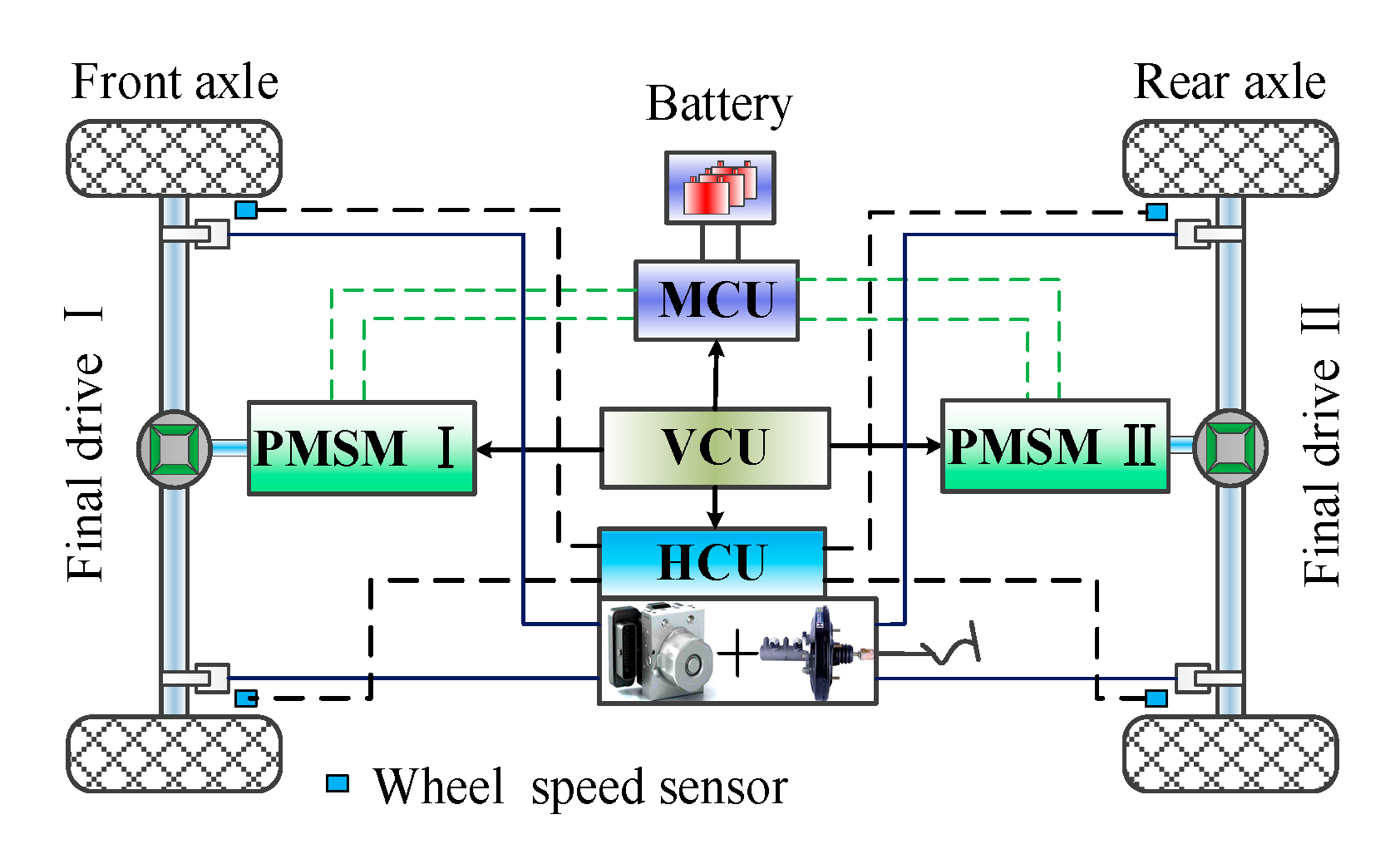
The pure electric vehicle analyzed in this paper is a front–rear centralized dual-motor driving system with two three-phase permanent magnet synchronous motors (PMSM), as shown in Figure 1. The driving forces are transmitted to the wheels from the motors through final drives I and II. The vehicle-state variables, such as vehicle speed, braking pedal displacement, and battery state of charge (SOC), are collected by an electronic control system and transmitted to the vehicle control unit (VCU) via a controller area network (CAN) bus, and the braking torques required of the MBS and the HBS are determined by the vehicle control unit. The motor braking torque and hydraulic braking torque are controlled by the motor control unit (MCU) and hydraulic control unit (HCU), respectively. The basic parameters of the vehicle are shown in Table 1.
2.2. Dynamics Analysis of Braking
When a vehicle is braking, and the air resistance moment, rolling resistance moment, and moment of inertial generated by the rotating mass are ignored, the normal acting force of the ground on the front wheel [7] is
The normal force of the ground acting on the rear wheel is
where and are the normal acting force of the ground on the front and rear wheels; is wheelbase; denote the height of the center of mass of vehicle; and are the distance from the center of mass to front and rear axles; is the weight of vehicle; and represents the braking strength, and it is the ratio of the vehicle deceleration to the gravitational acceleration.
The dynamic equation of wheel rotation during braking is
where represent the moment of inertia of transmission equivalent to the wheel; denote brake force of ground; is the tire radius; is the braking torque acting on the wheel by PMSM I or PMSM II; is hydraulic braking torque; and is angular velocity of the wheel.
Dynamics equation of the vehicle transmission system during braking is
where denote vehicle speed; is acceleration of gravity; according to the working state of PMSM I, PMSM II, and HBS, , and is 0 or 1; and and are the gear ratio of the final drive I.
2.3. The Braking Force Distribution Control Strategies
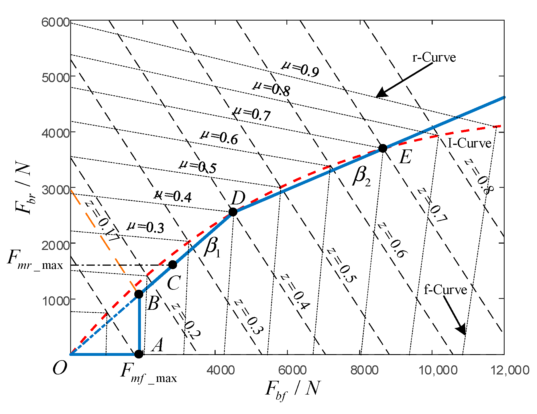
The distribution of braking force is determined by the braking state of the vehicle and must meet the requirements of the brake regulations. Due to deceleration during braking of the vehicle, the stable braking strength provided by the motors varies between 0.086 and 0.2. According to the theory of braking stability, the braking force distribution curve under the -Curve can ensure the stability of the vehicle; that is, to maintain the ability of straight-line driving of the vehicle during braking [16,17,18]. Therefore, the maximum braking strength provided by the motors in the pure electric braking mode is determined to be 0.17. The dynamic distribution control strategies based on the -Curve are shown in Figure 2.
The braking strength at points A, B, C, D, and E in Figure 2 are , , ,, and . -Curve is the ideal braking force distribution over the front and rear axles. and denote the braking force of the front and rear axles. and denote the maximum braking forces provided by the PMSM I and the PMSM II. The fixed braking force distribution coefficients of the front and rear axles are and . is the road adhesion coefficient.
The minimum speed of the vehicle at which the motors maintain a stable braking torque is ; the maximum speed of the vehicle at which the motors can perform regenerative braking is ; and the maximum state of charge in which the battery can be charged is . During braking, the speed of the vehicle and the SOC of the battery should obey the restriction that and , respectively. The motor and hydraulic braking force distribution based on the braking strength required by driver is as follows:
When and :
(1) , in order to guarantee the braking stability of the vehicle during braking, the PMSM I is given priority to provide braking force, the braking force is provided by PMSM I individually in this condition.
(2) , the braking force is provided by PMSM I and PMSM II simultaneously, and PMSM I provides the maximum braking force, the remaining force is provided by PMSM II.
(3) , the HBS starts to provide braking force in this condition, and the braking force of the front and rear axles are distributed according to the fixed braking force distribution coefficient . PMSM I maintains the maximum braking force and the insufficient braking force of the front axle is provided by the HBS. The braking force of PMSM II continues to increase with braking strength, until the maximum braking force of PMSM II is reached.
(4) , the required braking force is provided by the motor braking system and hydraulic braking system simultaneously in this condition. Both PMSM I and PMSM II are working at the maximum braking force that can be supplied, and the insufficient braking force of the front and rear axles are provided by the hydraulic braking system.
When or or , or , the braking force is provided only by the HBS, and the braking force at the front and rear axles are distributed according to the fixed braking force distribution coefficient and .
3. Modeling and Characteristics Analysis of Braking Systems
In order to obtain the dynamic response characteristics of the MBS and the HBS, a simulation model was established in MATLAB/Simulink (2016b, MathWorks, MA, USA) based on the mathematical models of the motor and the hydraulic brake system. In order to accurately control the hydraulic braking torque, a combined control method, which contains a PID controller and a fuzzy controller, was designed to control the brake pressure in each wheel cylinder.
3.1. The Modeling of PMSM
The main parameters of the PMSM used in this paper are shown in Table 2. The PMSM is a strong complex-coupling, high-order, and multivariable nonlinear system [19,20]. In order to realize the vector control of the motor, the mathematical model of the PMSM in the two-phase rotating reference frame (- axis) was used to establish the simulation model. The three-phase PMSM in the - axis can be described as [21]
The electromagnetic torque equation of the PMSM in - axis is
where and are the armature voltage components in the - axis, respectively; and denote the armature current in the - axis, respectively; and represent the equivalent armature inductance in the - axis respectively; is the rotor flux corresponding to the permanent magnet; represent the stator resistance; denote the rotational angular velocity of - axis; and represents the pole pairs of motor.
3.2. The Modeling of Hydraulic Components
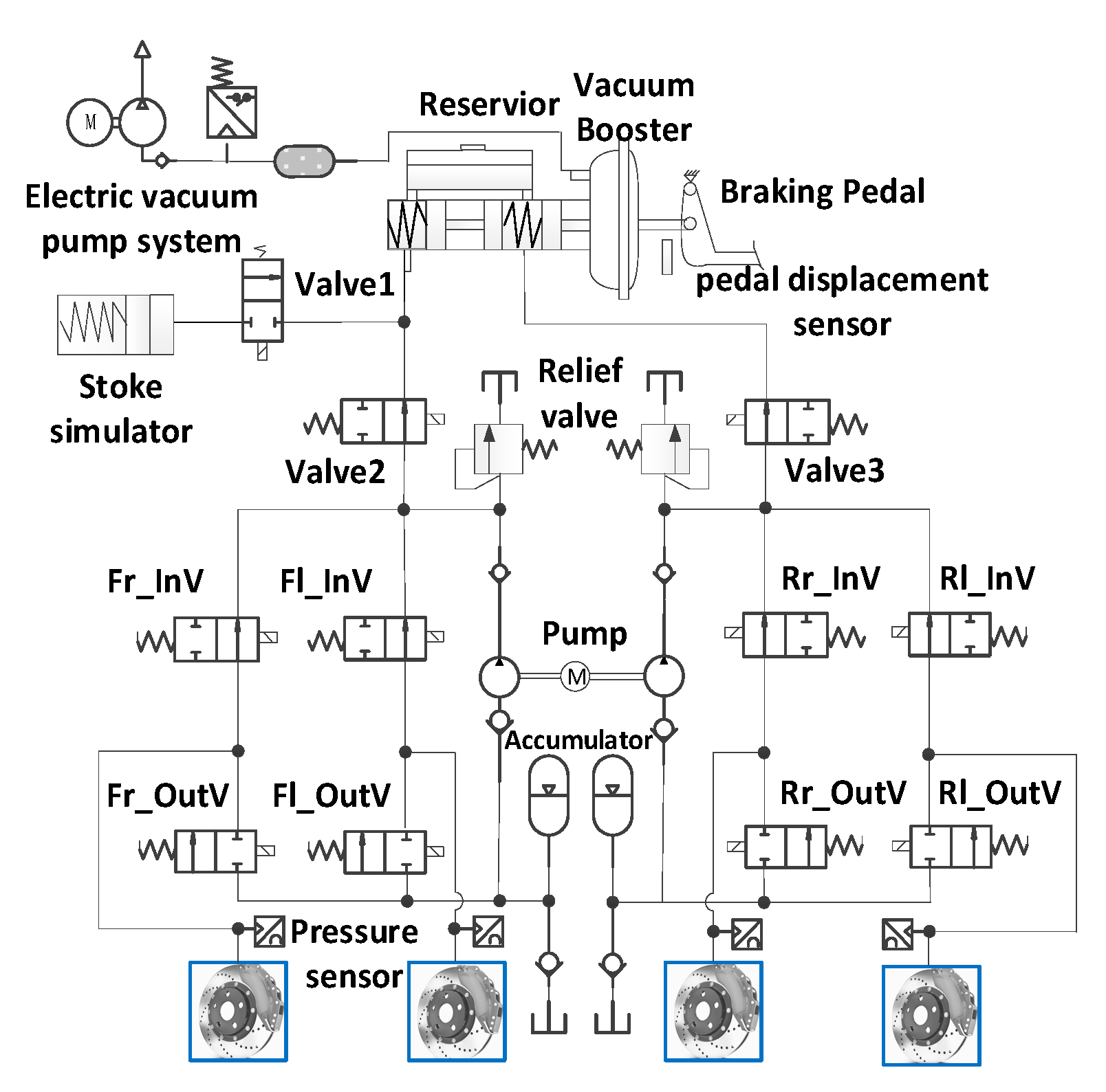
The hydraulic braking system mainly includes system components, such as the brake master cylinder, the wheel cylinder, and the brake pedal simulator, as well as the control components, such as the high-speed on–off valve [22,23]. The structure of the hydraulic braking system used in this article is shown in Figure 3. The pressure of the wheel cylinder is adjusted by the high-speed on–off valve to meet the requirement of the hydraulic braking torque, while the hydraulic braking torque is directly determined by the pressure in the wheel cylinder; i.e., these components reflect the dynamic characteristics of the HBS. Therefore, the mathematical models of the high-speed on–off valves and the brake wheel cylinders are mainly described.
3.2.1. The Modeling of the High-Speed On–Off Valve
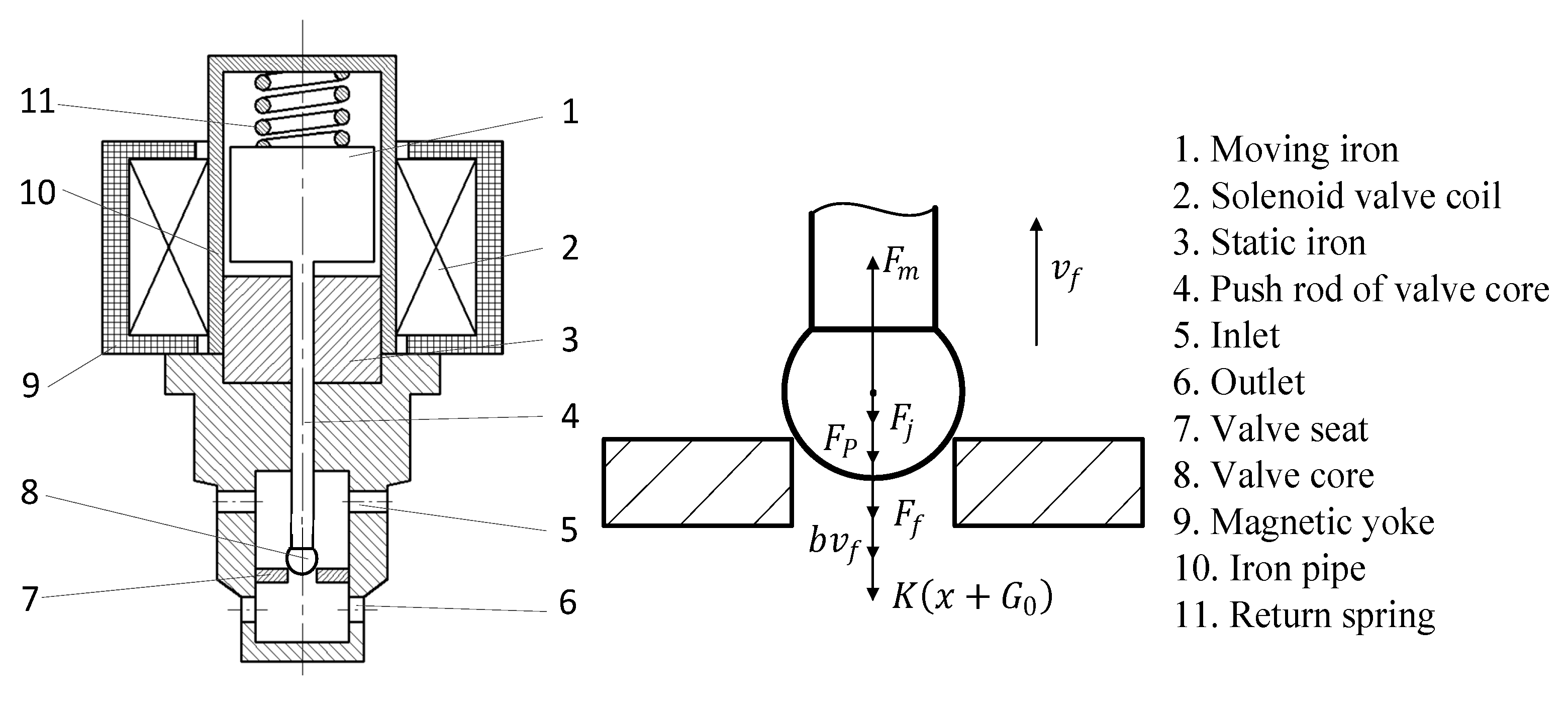
The pressure of a brake wheel cylinder is controlled by a pair of high-speed on–off valves: the inlet valve that is normally opened and the outlet valve that is normally closed. The structure of the outlet valve and the force analysis of the valve core are shown in the Figure 4. The key parameters of the high-speed on–off valves selected in this paper are summarized in Table 3.
According to the control signals of the vehicle controller, the pressure in the wheel cylinder is adjusted by the hydraulic controller through the combined control of the inlet and outlet valves. Through the force analysis of the valve core in Figure 4, the kinetic equation of the valve core can be obtained [24]:
where is the electro-magnetic force; denotes the frictional force, it takes an estimated value of 0.01 N in this study; represents the jet force; is the flow force of the core assembly; is the mass of the core assembly; is the stiffness of the return spring; and are the velocity viscosity coefficient and the displacement of the core, respectively; and represents the return spring’s pre-compression force.
3.2.2. The Modeling of the Wheel Cylinder
During hydraulic braking, the dynamic characteristics of the wheel cylinder piston can be expressed as a spring–mass–damper system, and its dynamic equation [25] is
where represents pre-tightening force; denotes the wheel cylinder pressure; is the effective action area of the piston; denotes the mass of piston; represents the displacement of piston; is the damping of the brake; and is the equivalent stiffness.
The relationship between the pressure in the wheel cylinder and the hydraulic braking torque in front and rear axles can be expressed as [13]
where and represent the hydraulic braking torque of the front and rear axles, respectively; and are the brake factors of the front and rear axles; and denote the diameter of the front and rear wheel cylinders; and and represent the effective radius of the front and rear wheel brake discs.
The key parameters of the front and rear brakes is shown in Table 4.
3.2.3. Design of a Combined Controller for Hydraulic Braking Torque
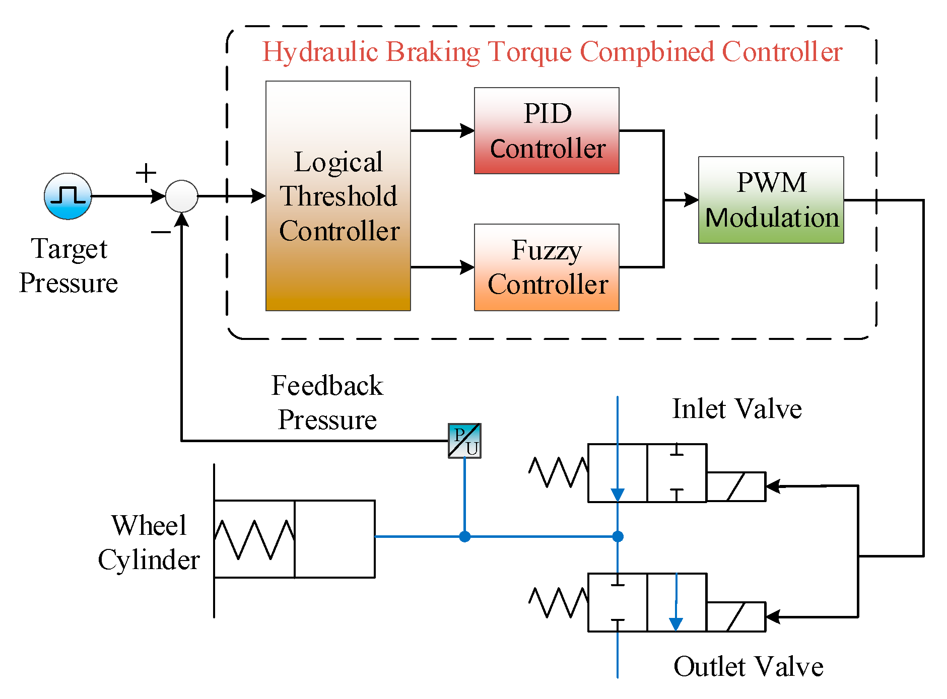
The HBS should have good control performance to achieve a fast and accurate response to the hydraulic braking force. A cooperative control strategy is used to improve the response speed and control the accuracy of the hydraulic braking torque. When the pressure error between the target pressure and the tracking pressure is larger than the value of the threshold, the PID controller controls the wheel cylinder pressure to achieve a rapid adjustment. Conversely, when the pressure error is smaller than the value of the threshold, the fuzzy controller is used to stabilize the wheel cylinder pressure near the target pressure and reduce the hydraulic pressure fluctuation [26,27]. The control schematic is shown in Figure 5. Wheel cylinder control is determined by the logical threshold controller according to the pressure error , and then either the PID or fuzzy controller determines the duty ratio of the high-speed on–off valve. The inlet and outlet valves of the wheel cylinder are directly controlled by PWM (pulse width modulation). Thus, the tracking pressure of the wheel cylinder follows the target pressure. A threshold value of 0.5 bar was set for as simulation results indicated that both the response speed and the control accuracy of the pressure in the wheel cylinder were optimal at this level.
When the pressure error is larger than the value of the threshold, the PID controller is used to adjust the pressure in the wheel cylinder, so that the tracking pressure in the wheel cylinder rapidly responds to the target pressure. The mathematical model of the PID controller [24] is
where is the duty ratio of the PWM signal; , , and are the proportional, integral, and differential coefficients of the PID controller, respectively; and are the time when the HBS starts and ends to work.
When the pressure error is smaller than the value of the threshold, the fuzzy controller is used to adjust the pressure of the wheel cylinder. The opening degree of the inlet and outlet valves are determined by the target pressure and the pressure error . When the target pressure is small (S’) and the pressure error is negative (N), the tracking pressure needs to be reduced, so that the duty ratio of the inlet valve takes a smaller value (S’) and the duty ratio of the outlet valve takes a larger value (VL’). When the target pressure is large (VL’) and the pressure error is positive (P), the tracking pressure needs to be increased, so that the duty ratio of the inlet valve takes a larger value (VL’) and the duty ratio of the outlet valve takes a smaller value (S’). The fuzzy controller rules for the degree of opening of the high-speed on–off valve are shown in Table 5 and Table 6.
In Table 5, N, Z, and P denote less than zero, equal to zero, and greater than zero, respectively; whereas S’, MS’, M’, ML’, L’, and VL’ represent small, small medium, medium, medium large, large, and very large, respectively.
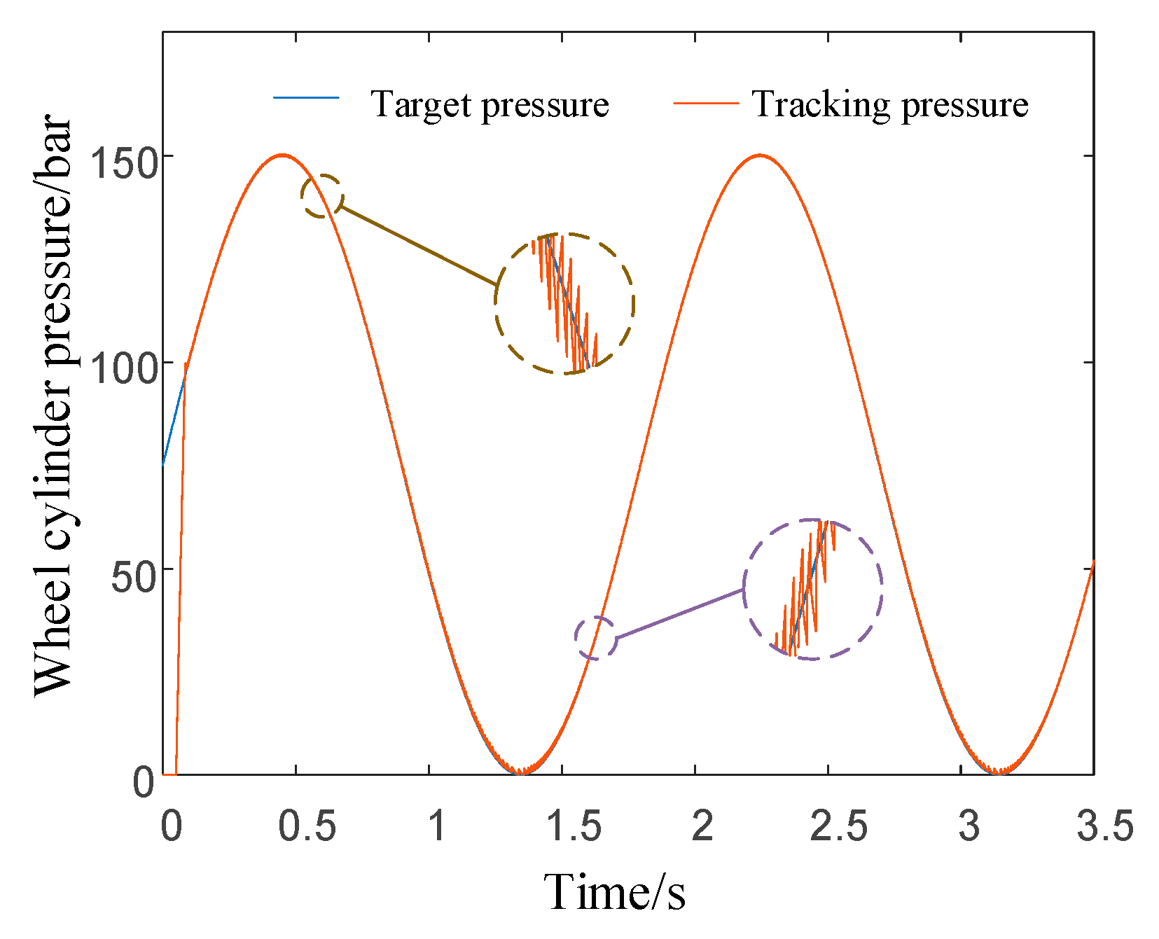
The pressure variation of a wheel cylinder controlled by the combined controller under the input of a sinusoidal signal is shown in Figure 6. The tracking pressure in the wheel cylinder is precisely controlled, and the pressure error between the target pressure and tracking pressure is very small.
3.3. Dynamic Characteristics Analysis of the MBS and the HBS
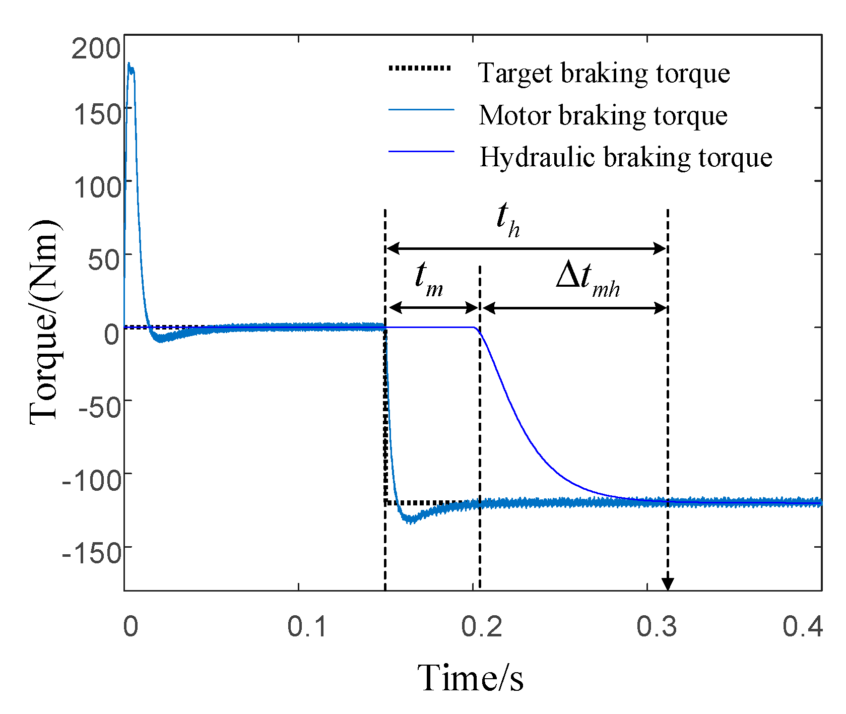
Using the mathematical models described above, a dynamic model of the electro-hydraulic composite braking system was built in MATLAB/Simulink, and a separate HBS physical model was built in the Simulink sub-module, Simscape. The dynamic responses of the MBS and HBS are shown in Figure 7. Under the input of the same demand braking torque, the response time of the MBS is , the response time of the HBS is , and the response time difference is . Compared with the HBS, the dynamic response of the MBS is fast, and the braking torque rise time is short, but there is a certain amount of overshoot. There are two main reasons for the differences in dynamic characteristics: In the initial stage of the hydraulic braking torque response, the HBS needs high-pressure brake fluid to fill the circuit and liquid chamber, and during the rising period of the hydraulic braking torque, there are viscosity resistance, flow force, and orifice compensation of the hydraulic braking system.
Because of the differences in dynamic response characteristics between the MBS and the HBS, the total braking torque fluctuates significantly during mode switching, which cannot meet the braking torque required by the driver, and may also lead to an increase in the jerk of the complete vehicle and the false trigger of the ABS braking, as shown in the simulation part of this study. So it is necessary to coordinate the motor braking torque and hydraulic braking torque in the process of mode switching, to ensure the stability of the braking torque during braking.
4. The Torque Coordinated Control Strategy of Mode Switching
4.1. The Condition Analysis of Mode Switching
By controlling the working state of the motor and switching of the HBS coupling valve, the electro-hydraulic composite braking system of the electric vehicle can realize various braking modes. According to the braking force distribution control strategies of this paper, the working state of each component of the braking system of each braking mode are shown in Table 7. Based on the response differences between the MBS and HBS, and setting aside the discontinuous change due to brake pedal action, the processes responsible for the torque fluctuation during mode switching mainly exist in the working conditions that the braking torque step changed. Therefore, the coordinated control strategy is mainly applied to the braking conditions in which the braking torque of the MBS or HBS step changes.
In Table 7, “●” represents MBS working or HBS working, and “○” represents MBS not in operation or HBS not in operation.
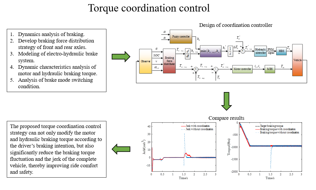
4.2. The Design of the Coordination Controller
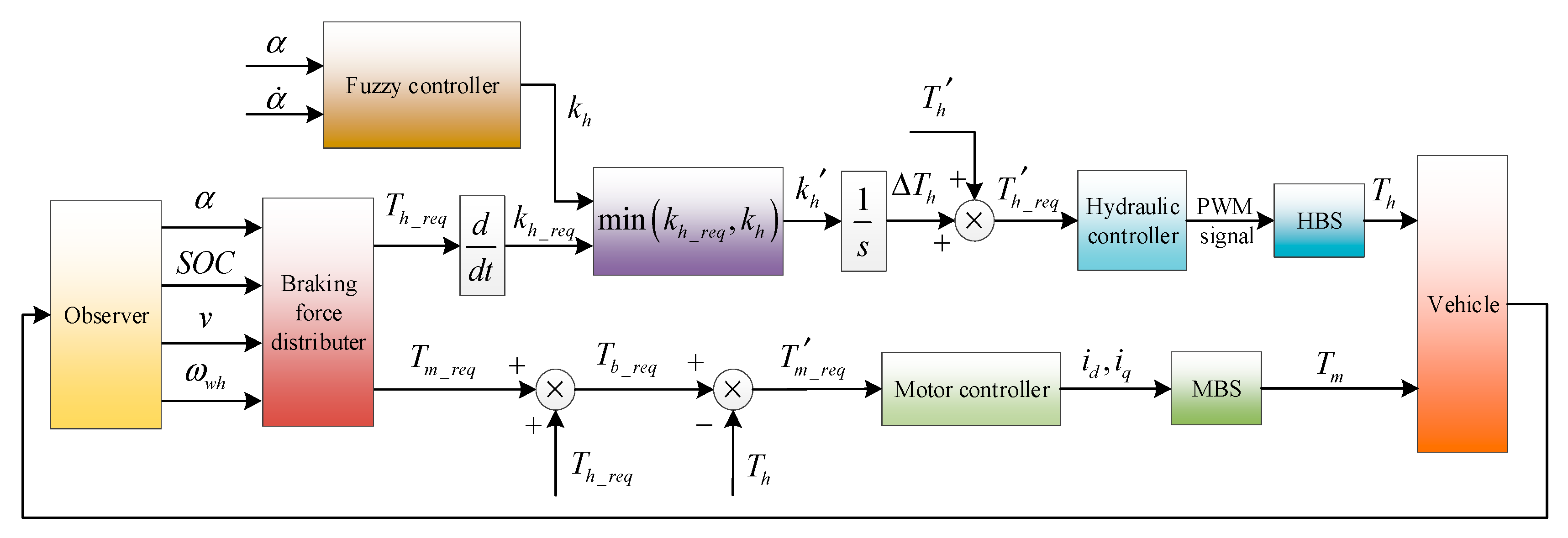
The dynamic coordination control strategy of brake mode switching developed in this paper is shown in the Figure 8. Firstly, the target hydraulic braking torque, , and the target motor braking torque, , are preliminarily distributed based on the vehicle state parameters by the braking force distribution controller. Secondly, the target hydraulic braking torque is modified through fuzzy control rules based on the pedal opening and its change rate, to reflect the driver’s braking intention. Then, the target motor braking torque is corrected by the actual hydraulic braking torque () output by the HBS, and the rapid response of the MBS is used to compensate for the hydraulic braking torque, to achieve a smooth transition of the braking mode. Finally, the HBS and the MBS are controlled by the hydraulic and motor braking controller, respectively, to respond to the modified target braking torque and , and then output the actual hydraulic braking torque, , and actual motor braking torque, , to decelerate the vehicle.
4.2.1. The Modification of Target Hydraulic Braking Torque
The target change rates of target hydraulic braking torque during braking are
where represents the target change rates of hydraulic braking torque.
During the mode switching, the upper limit of the change rate of the hydraulic braking torque, , is determined by the fuzzy controller, which is designed based on the brake pedal stroke, , and its change rate, . Then the upper limit of the change rate, , is compared with the target change rate , to determine the modified target change rate.
The increment of the modified target hydraulic braking torque, , can be obtained by the integration of the modified target change rate. Therefore, the modified target braking torque of the HBS is
where represents the target braking torque of the HBS modified by the coordination controller; and is the initial braking torque at the moment when the mode is switched.
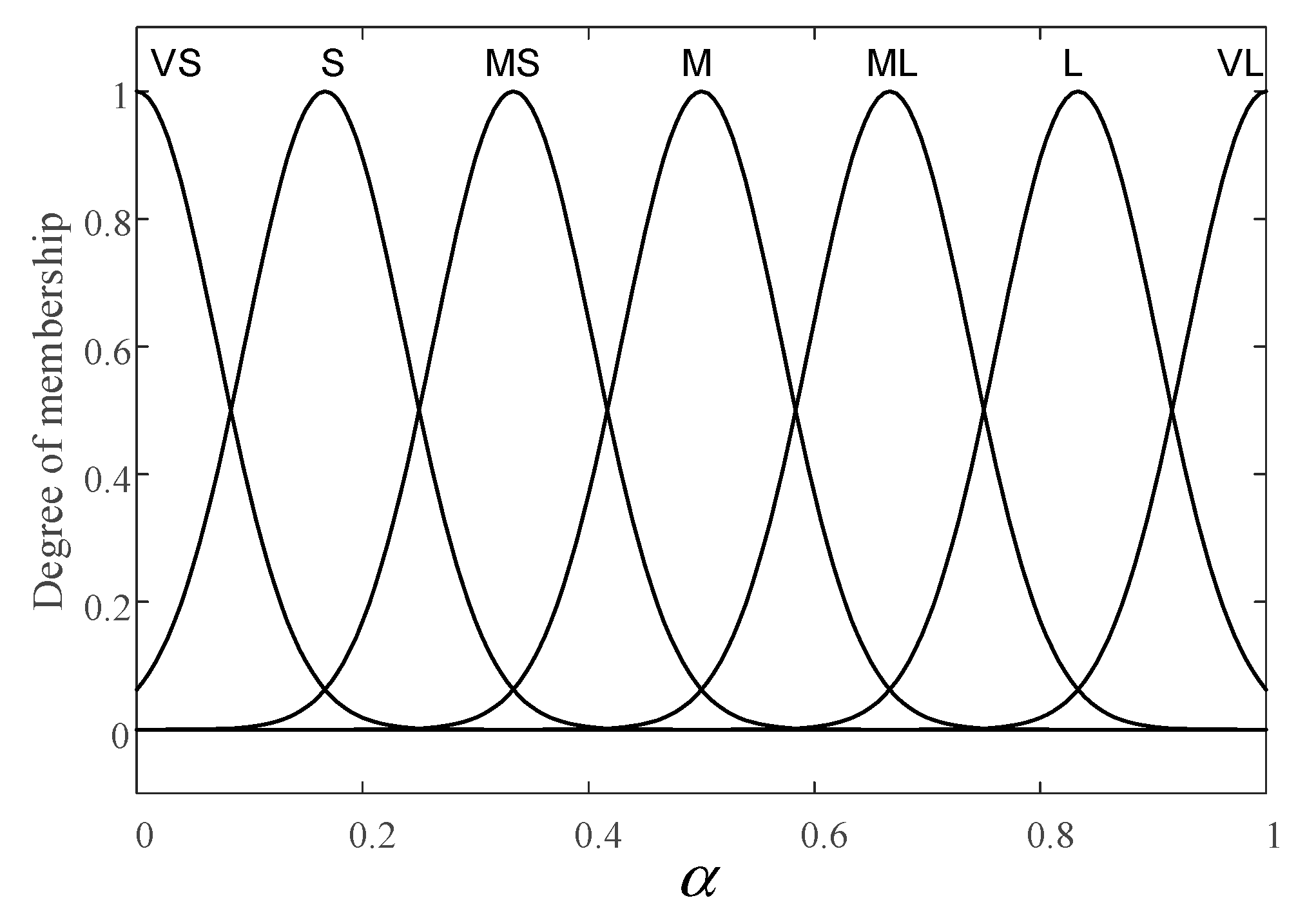
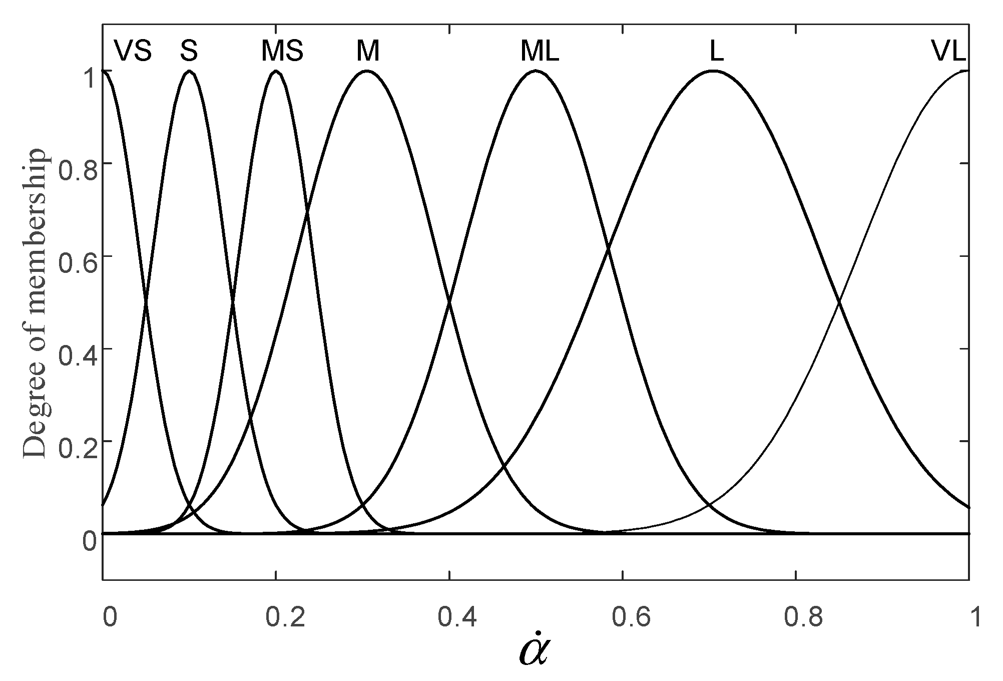
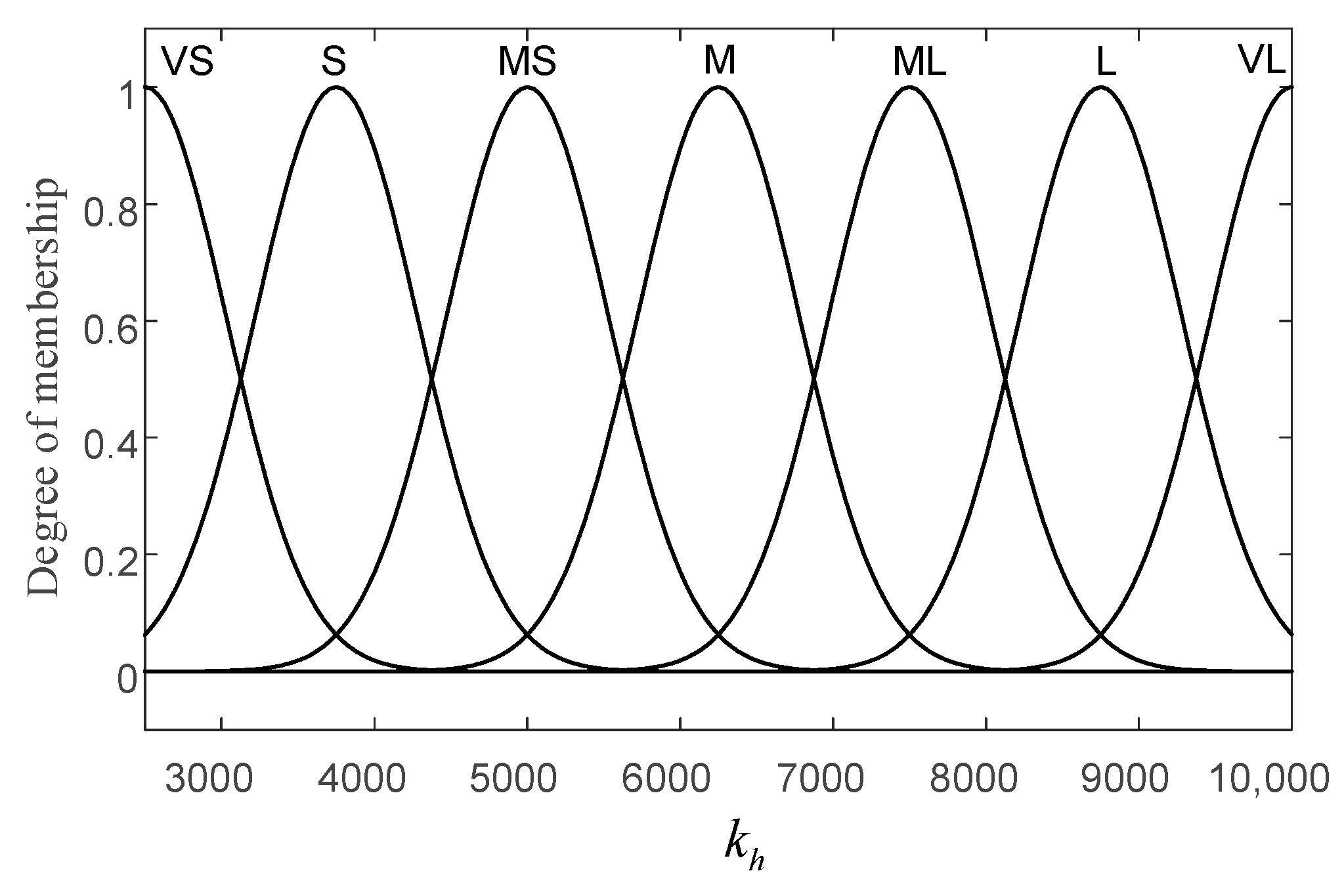
During mode switching, the driver’s braking intention is reflected by the brake pedal stroke and the brake pedal stroke change rate. Then the fuzzy controller outputs the upper limit of the change rate of the target hydraulic braking torque, so as to realize the modification of the target hydraulic braking torque. The fuzzy subsets of brake pedal stroke, brake pedal stroke change rate, and the upper limit of the change rate of the hydraulic braking torque are ; therefore, the input and output of the fuzzy controller can be described as
where VS, S, MS, M, ML, L, and VL represent very small, small medium, medium, medium large, large, and very large, respectively.
The fuzzy control rules are shown in Table 8, and the membership function of input and output variables of fuzzy controller are shown in Figure 9, Figure 10 and Figure 11. The fuzzy control rules are formulated based on the following experiences:
Criterion 1: If and are S, then is MS. In this case, the brake pedal stroke and its change rate are small; it can be considered that the driver pays more attention to the ride comfort during mode switching, and the upper limit of the change rate of the hydraulic braking torque takes a medium-small value.
Criterion 2: If is S and is L, then is ML. In this case, the braking pedal opening is small and its change rate is large, which indicates that the driver pays more attention to the braking safety during mode switching. Therefore, the upper limit of the change rate of the hydraulic braking torque takes a medium-large value.
Criterion 3: If is VL and is S, then is L. In this case, the braking pedal opening is very large and its change rate is small, indicating that the driver pays attention to both braking safety and ride comfort during mode switching, so the upper limit of the change rate of the hydraulic braking torque takes a large value.
According to the modified target hydraulic braking torque , the hydraulic controller determines the duty ratio of high-speed on–off valve, and directly controls the inlet valve and outlet valve of wheel cylinder through PWM modulation, so as to make the tracking pressure of wheel cylinders follow the modified target pressure changes.
4.2.2. The Modification of Target Motor Braking Torque
According to the analysis in Section 3.3 of this paper, the response time of the MBS is shorter than that of the HBS, thus the rapid response of MBS can be used to compensate for the insufficient braking torque caused by the slow response of HBS, so as to solve the fluctuation of total braking torque and the jerk of the complete vehicle during brake mode switching. Therefore, during mode switching, the MBS need to provide the target motor brake torque , which is determined by the braking force distribution controller and additionally provide the difference between the target hydraulic braking torque and the current actual hydraulic braking torque ; that is,
The sum of target hydraulic braking torque and target motor braking torque is the total braking torque required by the driver, so Equation (15) can be rewritten as
The motor control parameters and are output by the motor controller according to the modified target motor braking torque , so that the MBS outputs the actual motor braking torque to act on the vehicle.
According to the braking force distribution control strategy of this paper, the HBS starts to provide braking torque when the braking strength required by driver is greater than . If the braking torque required by driver changes, in order to maintain the coordinated compensation ability of the MBS to the hydraulic braking torque during mode switching, the target braking torque allocated by the braking force distribution controller to the MBS should be smaller than the maximum braking torque that can be provided by the MBS. When the braking torque required by the driver continues to increase, and the required braking strength satisfy , the target braking torque determined by braking force distribution controller should increase to gradually. If the braking torque required by driver remains unchanged, the maximum braking torque that can be provided by the MBS remains at at the braking torque distribution stage.
5. Simulation and Analysis
The forward simulation model of a pure electric vehicle was established in MATLAB/Simulink in this study, as shown in Figure 12. This simulation model includes the PMSM I and PMSM II models, the HBS model, the battery model, the vehicle longitudinal resistance model, and the controller model. Because the switching between different braking modes is similar, a specific mode switching can be selected for verification and analysis. The same conclusion can be obtained by the simulation of other switching processes with the proposed torque coordinated control method.
The conditions of constant and variable braking strength are simulated to verify the effectiveness of the dynamic coordination control strategy. For the switching from a constant braking strength, the mode switching between the pure electric and pure hydraulic braking modes were selected for the simulation test, and the motor braking switching to a hybrid braking mode was selected for simulation verification in the mode switching of variable braking strength. In the switching from a constant braking strength, the motor and hydraulic braking torque with coordination will respond to the modified target braking torque output by the coordination controller, while the motor and hydraulic braking torque without coordination will respond to the target braking torque that is assigned by the braking force distributor. Under the condition of a variable braking strength, the braking torque and the jerk of the complete vehicle, focusing on safety and ride comfort, were compared, to verify whether the coordinated control strategy reflects the driver’s braking intention.
5.1. Simulation and Verification of the Constant Braking Strength of Mode Switching
5.1.1. Switch from Pure Hydraulic to Pure Electric Braking Mode
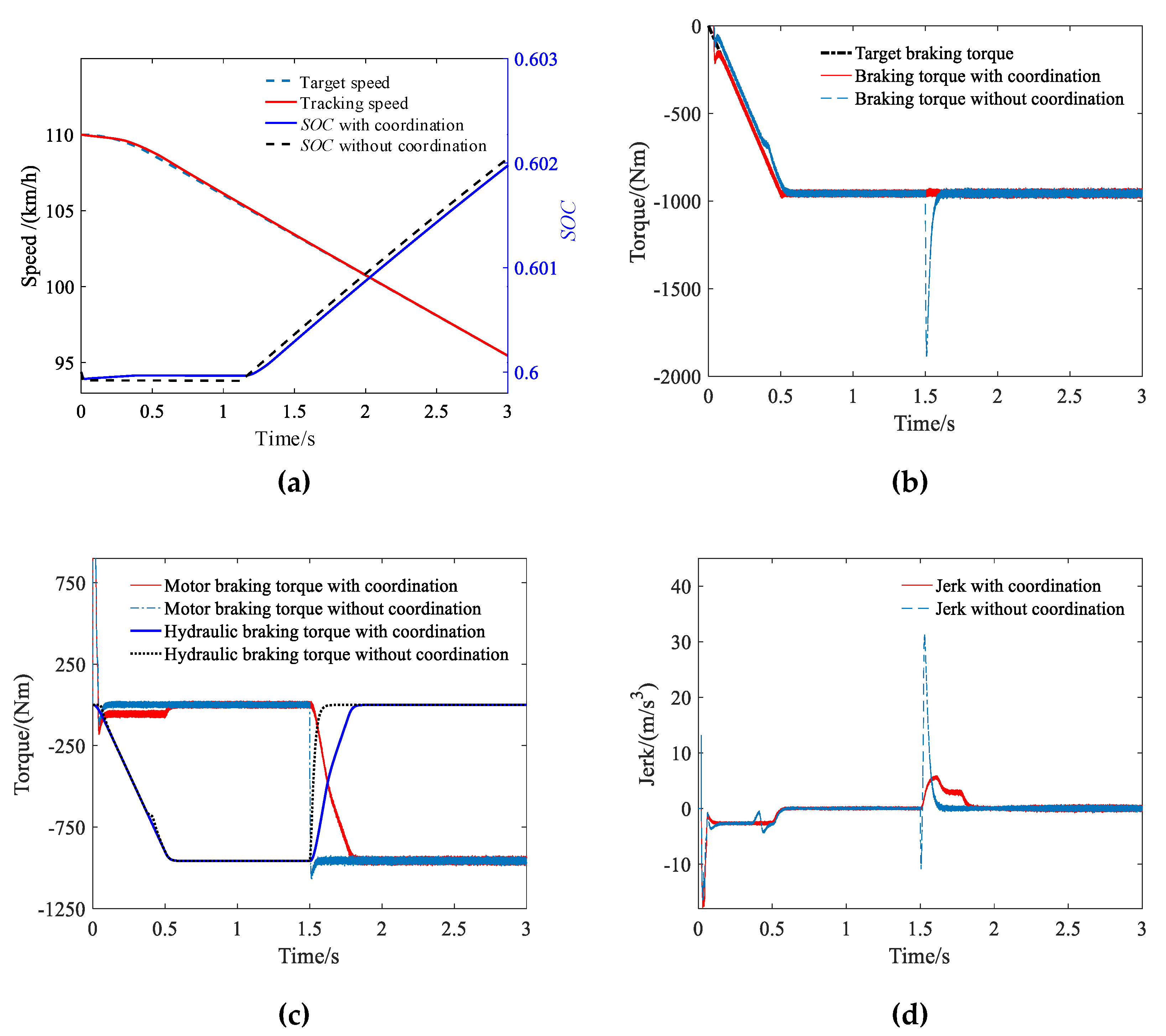
The speed variation condition shown in Figure 13a is designed to verify the effectiveness of the coordinated control algorithm during pure hydraulic switching to the pure electric braking mode. In this braking condition, the initial speed of the vehicle is 110 km/h, the initial SOC of the battery is 0.6, and the road adhesion coefficient is 0.8. The braking strength required by the driver is increased from 0 to 0.15 within 0 to 0.5 s, and then remains constant.
At the start of braking, the speed of the vehicle is too high for the motors to perform regenerative braking; hence, braking torque is provided by the HBS. After 1.5 s, when the speed of the vehicle has decreased sufficiently, the braking mode switches to pure electric, and braking torque is provided only by the MBS. Because of the compensation of the motor braking torque to the hydraulic braking torque, the SOC with coordination is slightly higher than the SOC without coordination at the start of braking; moreover, the slow increase of the motor braking torque with coordination during mode switching resulted in a lower SOC with coordination than that without coordination, as shown in Figure 13a. As shown in Figure 13b, during the increase of braking strength, the response speed of the HBS is slow due to the orifice compensation and viscosity resistance within the HBS, hence the total braking torque without coordination cannot quickly respond to the target total braking torque required by the driver. The coordinated total braking torque follows the target total braking torque well because the MBS can compensate for the insufficient braking torque caused by the slow response of the HBS.
During mode switching, Figure 13c demonstrates that the motor braking torque without coordination increased rapidly, while the slower responding HBS was still providing a high braking torque. According to Figure 13d, the rapid increase in total braking torque without coordination resulted in a 31.29 m/s3 jerk of the complete vehicle. In contrast, the motor braking torque with coordination increases as the hydraulic braking torque decreases, and the total braking torque is maintained at a constant level as far as possible. The maximum jerk of the vehicle was 5.91 m/s3; thus, the ride comfort of the vehicle is improved during mode switching.
5.1.2. Switch from Pure Electric to Pure Hydraulic Braking Mode
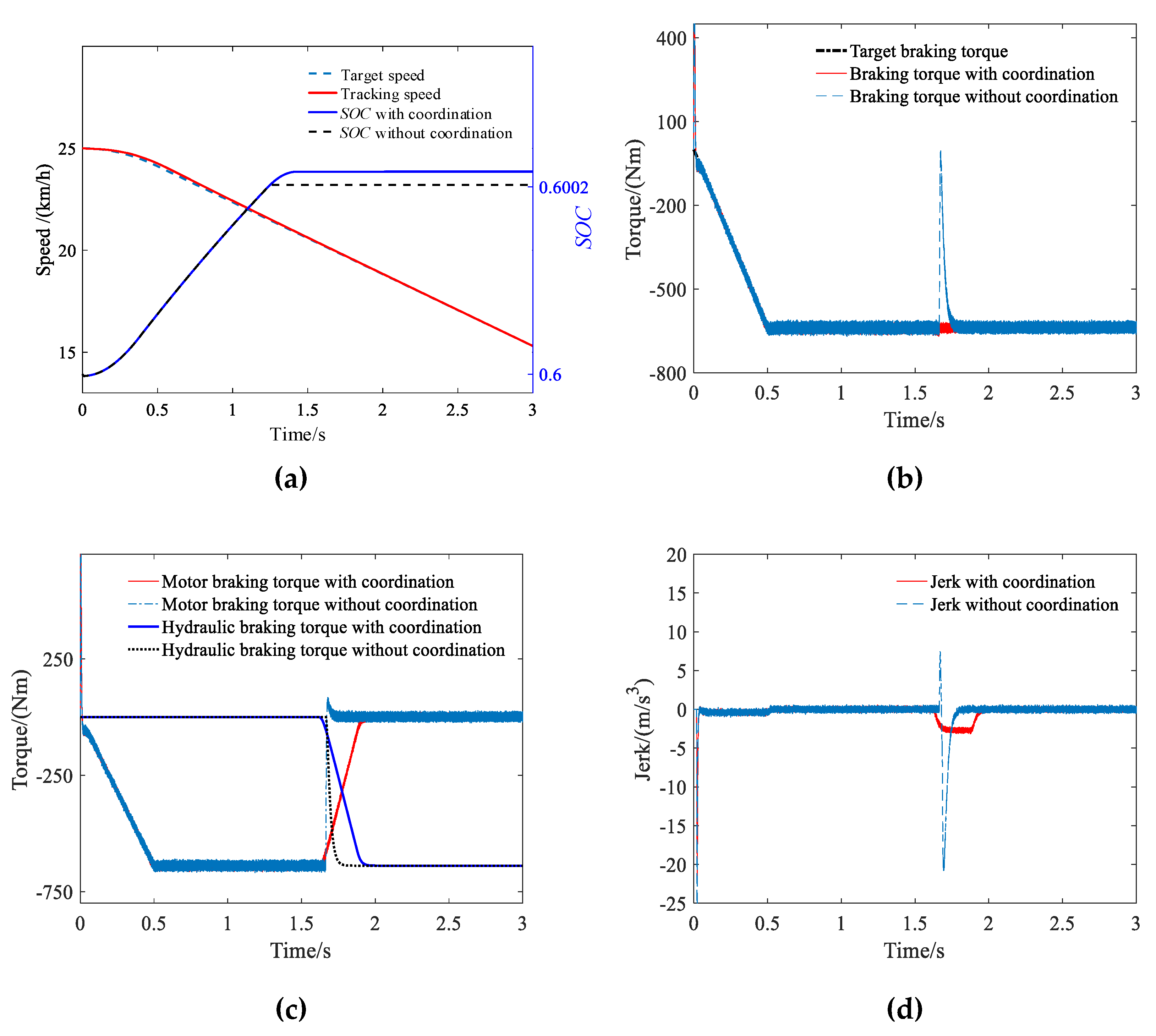
The speed variation condition shown in Figure 14a is designed to verify the effectiveness of the coordinated control algorithm during pure electric switching to the pure hydraulic braking mode. In this braking condition, the initial speed of the vehicle is 25 km/h, the initial SOC of the battery is 0.6, and the road adhesion coefficient is 0.8. The braking strength required by driver increased from 0 to 0.1 within 0 to 0.5 s, and then remains unchanged.
With the deceleration of the vehicle, the vehicle speed was reduced to 20 km/h at 1.67s, which is too slow for the MBS to maintain a stable regenerative braking torque; hence, the braking mode is switched from pure electric to pure hydraulic. Due to the coordination of motor braking torque to hydraulic braking torque during mode switching, the SOC with coordination is higher than that without coordination, as shown in Figure 14a. The simulation results of Figure 14b,c show that the mode switching without coordination cannot provide the braking torque required by the driver because of the rapid withdrawal of the motor braking torque, giving a wrong braking felling to the driver, resulting in a mis-operation by the driver. With coordination, the motor braking torque decreases as the hydraulic braking torque increases, creating a smooth transition, so that the total braking torque changes gradually and the speed of vehicle is steadily reduced. According to Figure 14d, the maximum jerk of the complete vehicle during mode switching with and without coordination was -3.14 m/s3 and -21.18 m/s3, respectively. Thus, the coordination control strategy improves the vehicle’s safety and ride comfort during braking mode switching.
5.2. Simulation and Verification of Variable Braking Strength of Mode Switching
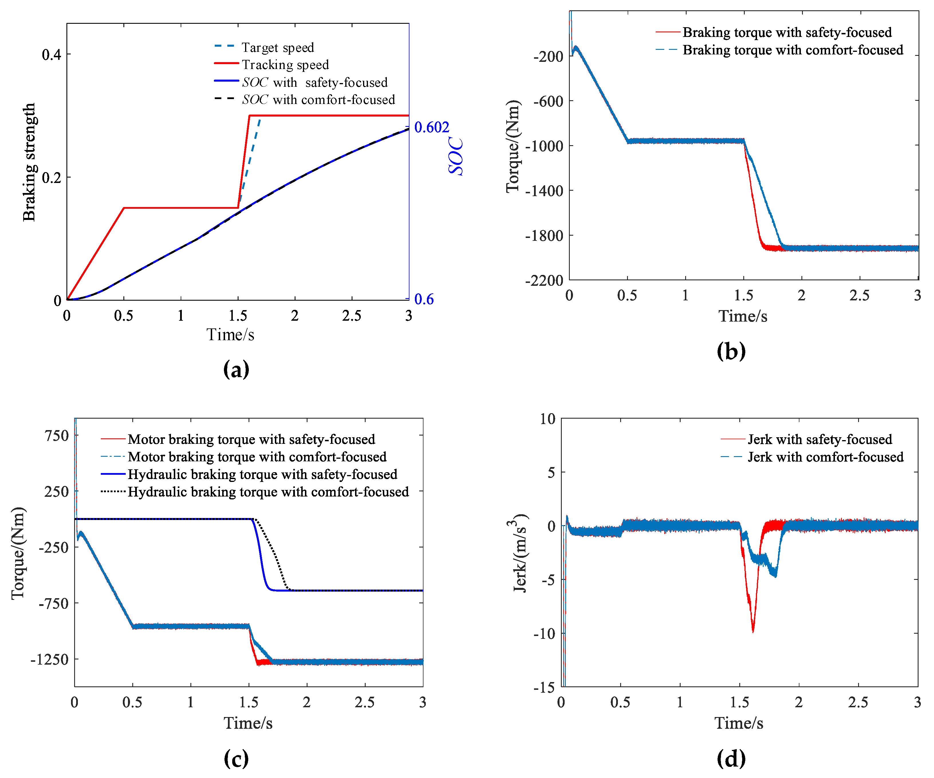
Under the condition of a variable braking strength, the initial speed of vehicle is 60 km/h, the initial SOC of battery is 0.6, and the road adhesion coefficient is 0.8. The braking strength required by the driver is increased from 0 to 0.1 within 0 to 0.5 s, and then remains unchanged. At 1.5 s, the driver depressed the brake pedal with two different brake pedal stroke change rates, and the braking strength gradually increases to 0.3. The variation in the braking strength is shown in Figure 15a.
The driver depressed the brake pedal to the same opening with two different brake pedal stroke change rates; therefore, both the switching processes are switched from pure electric to the hybrid braking mode. Because the change rate in brake pedal stroke is different, one switching process focuses on brake safety while the other focuses on ride comfort. The simulation results in Figure 15 are all obtained by the coordinated control strategy proposed in this paper. It can be seen from Figure 15a that since the variation in each braking torque is almost the same for both the safety-focused and comfort-focused intentions, the SOC changes of the two braking intention are almost the same, but the SOC with a safety-focused intention is slightly higher than that of the comfort-focused intention.
As shown in Figure 15b, c, since the motor and hydraulic braking torque is modified by the torque coordination controller according to the different braking intentions of the driver, the coordinated total braking torque, motor, and hydraulic braking torque that focus on ride comfort are changed more gently than that focusing on braking safety. As shown in Figure 15d, the jerk of the vehicle during mode switching that focuses on ride comfort is −4.84 m/s3, while the mode switching that focuses on braking safety is −9.97m/s3. The simulation results show that the coordinated control strategy of this paper can modify the motor and hydraulic braking torque reasonably according to the driver’s braking intention, so as to take into account the braking safety and ride comfort during braking mode switching.
6. Conclusions
The configuration of a four-wheel-drive pure electric vehicle with a dual motor is considered in this paper, and a braking torque dynamic coordinated control strategy, based on the braking intention of the driver, is proposed. The dynamic coordinated control strategy effectively reduces the torque fluctuation and the jerk of the complete vehicle during mode switching.
A controller combining a PID controller and a fuzzy controller is used to adjust the pressure in the wheel cylinder of the HBS to achieve precise control of the hydraulic braking torque. The brake pedal stroke and its change rate are used to reflect the braking intention of the driver, and to modify the target hydraulic braking torque based on a fuzzy control algorithm according to whether the driver pays more attention to brake safety or ride comfort. At the same time, the rapid response of the MBS is used to compensate for the insufficient braking torque caused by the slow response of the HBS, so as to ensure the ride comfort and stability of the braking during mode switching.
Based on the mathematical model of the electro-hydraulic composite braking system, a simulation verification platform is constructed. The typical mode switching of the constant and variable braking strength conditions are simulated to verify the effectiveness of the dynamic coordinated control strategy. The simulation results show that the torque coordination control strategy described in this paper can not only modify the motor and hydraulic braking torque according to the driver’s braking intention, but also significantly reduce the braking torque fluctuation and the jerk of the complete vehicle, thereby improving ride comfort and safety. The influence of the proposed control strategy on energy recovery mainly depends on the type of mode switching condition.
Intelligent transportation system (ITS) and vehicle-to-vehicle communication (V2V) are future development trends; therefore, in future research, the authors will combine ITS to make active predictions of braking mode. In addition, energy consumption will be considered by reducing the frequency of mode switching.
Author Contributions
Conceptualization, Y.Y. and Y.H.; methodology, Y.Y. and Y.H.; software, Y.H. and Z.C.; validation, Y.H., Z.C. and C.F.; formal analysis, Y.Y.; investigation, Y.H.; resources, Y.Y. and Y.H.; data curation, Z.Y.; writing—original draft preparation, Y.H.; writing—review and editing, Y.Y., Y.H. and C.F.; visualization, Y.H.; supervision, Y.Y., C.F. and Z.Y.; project administration, Y.Y., C.F. and Z.Y.; funding acquisition, Y.Y. and C.F. All authors have read and agreed to the published version of the manuscript.
Funding
This research was funded by the National Key R&D Program of China (grant No. 2018YFB0106100), and the National Natural Science Foundation of China (grant No.51575063).
Conflicts of Interest
The authors declare no conflict of interest.
References
- Niu, G.; Arribas, A.P.; Salameh, M.; Krishnamurthy, M.; Garcia, J.M. Hybrid energy storage systems in electric vehicle. In Proceedings of the Transportation Electrification Conference and Expo (ITEC), Dearborn, MI, USA, 14–17 June 2015; pp. 1–6. [Google Scholar]
- Wu, J.; Wang, X.; Li, L.; Qin, C.; Du, Y. Hierarchical control strategy with battery aging consideration for hybrid electric vehicle regenerative braking control. Energy 2018, 145, 301–312. [Google Scholar] [CrossRef]
- Dizqah, A.M.; Lenzo, B.; Sorniotti, A.; Gruber, P.; Fallah, S.; De Smet, J. A Fast and Parametric Torque Distribution Strategy for Four-Wheel-Drive Energy-Efficient Electric Vehicles. IEEE Trans. Ind. Electron. 2016, 63, 4367–4376. [Google Scholar] [CrossRef] [Green Version]
- Niu, G.; Shang, F.; Krishnamurthy, M.; Garcia, J.M. Design and Analysis of an Electric Hydraulic Hybrid Powertrain in Electric Vehicles. IEEE Trans. Transp. Electrif. 2017, 3, 48–57. [Google Scholar] [CrossRef]
- Sun, F.; Liu, W.; He, H.; Guo, H. An integrated control strategy for the composite braking system of an electric vehicle with independently driven axles. Veh. Syst. Dyn. 2016, 54, 1031–1052. [Google Scholar] [CrossRef]
- Shi, J.; Wu, J.; Zhu, B.; Zhao, Y.; Deng, W.; Chen, X. Design of Anti-lock Braking System Based on Regenerative Braking for Distributed Drive Electric Vehicle. SAE Int. J. Passeng. Cars-Electron. Electr. Syst. 2018, 11, 205–218. [Google Scholar] [CrossRef]
- Sun, H.; Wang, H.; Zhao, X. Line Braking Torque Allocation Scheme for Minimal Braking Loss of Four-Wheel-Drive Electric Vehicles. IEEE Trans. Veh. Technol. 2019, 68, 180–192. [Google Scholar] [CrossRef]
- Okano, T.; Sakai, S.; Uchida, T. Braking Performance Improvement for Hybrid Electric Vehicle Based on Electric Motor’s Quick Torque Response. In Proceedings of the 19th International Electric Vehicle Symposium and Exhibition, Busan, Korea, 19–23 October 2002; pp. 1285–1296. [Google Scholar]
- He, C.; Zhang, J.; Wang, L.; Gou, J.; Li, Y. Dynamic Load Emulation of Regenerative Braking System during Electrified Vehicle Braking States Transition. In Proceedings of the Vehicle Power & Propulsion Conference, Beijing, China, 15–18 October 2013; pp. 1–5. [Google Scholar]
- Lv, C. Dynamical Blending Control of Regenerative Braking and Frictional Braking for Electrified Vehicles. Ph.D. Thesis, Tsinghua University, Beijing, China, 2015. [Google Scholar]
- Lv, C.; Zhang, J.; Li, Y.; Yuan, Y. Synthesis of a Hybrid-Observer-Based Active Controller for Compensating Powetrain Backlash Nonlinearity of an Electric Vehicle during Regenerative Braking. SAE Int. J. Altern. Powertrains 2015, 4, 190–198. [Google Scholar] [CrossRef]
- Zhang, Z.; Ma, R.; Wang, L.; Zhang, J. Novel PMSM Control for Anti-Lock Braking Considering Transmission Properties of the Electric Vehicle. IEEE Trans. Veh. Technol. 2018, 67, 10378–10386. [Google Scholar] [CrossRef]
- Yang, Y.; Wang, C.; Zhang, Q.; He, X. Torque Coordination Control during Braking Mode Switch for a Plug-in Hybrid Electric Vehicle. Energies 2017, 10, 1684. [Google Scholar] [CrossRef] [Green Version]
- Yu, Z.; Shi, B.; Xiong, L.; Han, W.; Shu, Q. Coordinated Control of Hybrid Braking Based on Integrated-Electro-hydraulic brake system. J. Tongji Univ. Nat. Sci. Ed. 2019, 47, 851–856. [Google Scholar] [CrossRef]
- Yu, Z.; Shi, B.; Xiong, L.; Han, W. Coordinated Control under Transitional Conditions in Hybrid Braking of Electric Vehicle. In Proceedings of the Brake Colloquium & Exhibition-36th Annual, Palm Desert, CA, USA, 14–17 October 2018; pp. 1–7. [Google Scholar]
- Xu, W.; Chen, H.; Zhao, H.; Ren, B. Torque optimization control for electric vehicles with four in-wheel motors equipped with regenerative braking system. Mechatronics 2019, 57, 95–108. [Google Scholar] [CrossRef]
- Fujimoto, H.; Harada, S. Model-Based Range Extension Control System for Electric Vehicles With Front and Rear Driving–Braking Force Distributions. IEEE Trans. Ind. Electron. 2015, 62, 3245–3254. [Google Scholar] [CrossRef]
- Qiu, C.; Wang, G.; Meng, M.; Shen, Y. A novel control strategy of regenerative braking system for electric vehicles under safety critical driving situations. Energy 2018, 149, 329–340. [Google Scholar] [CrossRef]
- Tehrani, M.G.; Kelkka, J.; Sopanen, J.; Mikkola, A.; Kerkkänen, K. Electric Vehicle Energy Consumption Simulation by Modeling the Efficiency of Driveline Components. SAE Int. J. Commer. Veh. 2016, 9, 31–39. [Google Scholar] [CrossRef]
- Zhong, Z.; Li, J.; Zhou, S.; Zhou, Y.; Jiang, S. Torque Ripple Description and Its Suppression through Flux Linkage Reconstruction. SAE Int. J. Altern. Powertrains 2017, 6, 175–182. [Google Scholar] [CrossRef]
- Shen, J.-Q.; Yuan, L.; Chen, M.-L.; Xie, Z. Flux Sliding-mode Observer Design for Sensorless Control of Dual Three-phase Interior Permanent Magnet Synchronous Motor. J. Electr. Eng. Technol. 2014, 9, 1614–1622. [Google Scholar] [CrossRef]
- Wang, C.; Zhao, W.; Li, W. Braking sense consistency strategy of electro-hydraulic composite braking system. Mech. Syst. Signal Process. 2018, 109, 196–219. [Google Scholar] [CrossRef]
- Han, W.; Xiong, L.; Yu, Z. A novel pressure control strategy of an electro-hydraulic brake system via fusion of control signals. Proc. Inst. Mech. Eng. Part D: J. Automob. Eng. 2019, 233, 3342–3357. [Google Scholar] [CrossRef]
- Yang, Y.; Li, G.; Zhang, Q. A Pressure-Coordinated Control for Vehicle Electro-Hydraulic Braking Systems. Energies 2018, 11, 2336. [Google Scholar] [CrossRef] [Green Version]
- Jiang, G.; Miao, X.; Wang, Y.; Chen, J.; Li, D.; Liu, L.; Muhammad, F. Real-time estimation of the pressure in the wheel cylinder with a hydraulic control unit in the vehicle braking control system based on the extended Kalman filter. Proc. Inst. Mech. Eng. Part D: J. Automob. Eng. 2016, 231, 1340–1352. [Google Scholar] [CrossRef]
- Kumar, Y.S.R.R.; Sonawane, D.B.; Subramanian, S.C. Application of PID control to an electro-pneumatic brake system. Int. J. Adv. Eng. Sci. Appl. Math. 2012, 4, 260–268. [Google Scholar] [CrossRef]
- Pi, D.; Cheng, Q.; Xie, B.; Wang, H.; Wang, X. A Novel Pneumatic Brake Pressure Control Algorithm for Regenerative Braking System of Electric Commercial Trucks. IEEE Access 2019, 7, 83372–83383. [Google Scholar] [CrossRef]
Figure 1.
Structure of a four-wheel-drive pure electric vehicle.

Figure 2.
Braking force distribution curve of the front and rear axles.

Figure 3.
The hydraulic braking system (HBS) structure diagram.

Figure 4.
The structure diagram of the outlet valve and the force analysis of the core.

Figure 5.
The pressure control algorithm of the wheel cylinder.

Figure 6.
The response of the wheel cylinder with a sinusoidal input.

Figure 7.
Dynamic response characteristics of the HBS and the motor braking system (MBS).

Figure 8.
Dynamic coordination control structure.

Figure 9.
Pedal opening degree membership function.

Figure 10.
Pedal opening change rate membership function.

Figure 11.
The upper limit of the change rate of the hydraulic braking torque membership function.

Figure 12.
The simulation model of the electric vehicle.

Figure 13.
Simulation results of the pure hydraulic switch to a pure motor braking mode under a constant braking strength: (a) The variation in vehicle speed and SOC, (b) the variation in total braking torque, (c) the variation in motor and hydraulic braking torque, and (d) the variation in vehicle jerk.

Figure 14.
Simulation results of the pure hydraulic switch to a pure motor braking mode under a constant braking strength: (a) The variation in vehicle speed and SOC, (b) the variation in total braking torque, (c) the variation in motor and hydraulic braking torque, and (d) the variation in vehicle jerk.

Figure 15.
Simulation results of the pure motor switch to a hybrid braking mode under variable braking strengths: (a) The variation in the braking strength and SOC, (b) the variation in total braking torque, (c) the variation in motor and hydraulic braking torque, and (d) the variation in vehicle jerk.


Table 1.
Parameters of the vehicle.
| Parameters | Value |
|---|---|
| Vehicle mass (kg) | 1800 |
| Rolling radius of tire (mm) | 362 |
| Height of the center of mass of vehicle (mm) | 560 |
| The distance between the center of mass and front axle (mm) | 1600 |
| The distance between the center of mass and rear axle (mm) | 1100 |
Table 2.
Key parameters of the motor.
| Parameters | PMSM I | PMSM II |
|---|---|---|
| Rated/peak power (kw) | 24.5/49 | 13.5/27 |
| Peak torque (Nm) | 155.1 | 171.9 |
| Rated/peak speed (rpm) | 3000/6000 | 1500/6000 |
Table 3.
Main parameters of the high-speed switch valve.
| Parameters | Value |
|---|---|
| Return Spring Stiffness (N/mm) | 1.6 |
| Moving-iron Mass (g) | 15 |
| Initial Air Gap (mm) | 0.3 |
| Coil Turns | 380 |
| Core Displacement (mm) | 0.22 |
| Spring Pre-tightening Force (N) | 7 |
Table 4.
Key parameters of front and rear wheel brakes.
| Parameters | Value |
|---|---|
| Front/rear brake cylinder diameter (mm) | 49/21 |
| Front/rear brake effective factor | 0.8 |
| Front/rear brake disc radius (mm) | 120 |
| Regulating valve pressure (bar) | 150 |
Table 5.
The fuzzy control rules of the inlet valve.
| Din | Δp(t) | |||
|---|---|---|---|---|
| N | Z | P | ||
| p(t) | S’ | S’ | MS’ | MS’ |
| MS’ | MS’ | M’ | M’ | |
| M’ | M’ | ML’ | ML’ | |
| ML’ | ML’ | L’ | L’ | |
| L’ | L’ | VL’ | VL’ | |
| VL’ | L’ | VL’ | VL’ | |
Table 6.
The fuzzy control rules of the outlet valve.
| Dout | Δp(t) | |||
|---|---|---|---|---|
| N | Z | P | ||
| p(t) | S’ | VL’ | VL’ | L’ |
| MS’ | L’ | L’ | ML’ | |
| M’ | ML’ | ML’ | M’ | |
| ML’ | M’ | M’ | MS’ | |
| L’ | MS’ | MS’ | S’ | |
| VL’ | MS’ | MS’ | S’ | |
Table 7.
The working state of each component in the different braking modes.
| Mode | PMSM I | PMSM II | HBS of Front Axle | HBS of Rear Axle |
|---|---|---|---|---|
| Pure electric braking | ● | ○ | ○ | ○ |
| ● | ● | ○ | ○ | |
| Hybrid braking | ● | ● | ● | ○ |
| ● | ● | ● | ● | |
| Pure hydraulic braking | ○ | ○ | ● | ● |
Table 8.
Fuzzy control rules of target hydraulic braking torque change rate.
| kh | ||||||||
|---|---|---|---|---|---|---|---|---|
| VS | S | MS | M | ML | L | VL | ||
| α | VS | VS | S | MS | M | M | ML | ML |
| S | S | MS | M | M | ML | ML | L | |
| MS | MS | M | M | ML | ML | L | L | |
| M | M | M | ML | ML | L | L | VL | |
| ML | M | ML | ML | L | L | VL | VL | |
| L | ML | ML | L | L | VL | VL | VL | |
| VL | ML | L | L | VL | VL | VL | VL | |
© 2020 by the authors. Licensee MDPI, Basel, Switzerland. This article is an open access article distributed under the terms and conditions of the Creative Commons Attribution (CC BY) license (http://creativecommons.org/licenses/by/4.0/).
Share and Cite
MDPI and ACS Style
Yang, Y.; He, Y.; Yang, Z.; Fu, C.; Cong, Z. Torque Coordination Control of an Electro-Hydraulic Composite Brake System During Mode Switching Based on Braking Intention. Energies 2020, 13, 2031. https://doi.org/10.3390/en13082031
AMA Style
Yang Y, He Y, Yang Z, Fu C, Cong Z. Torque Coordination Control of an Electro-Hydraulic Composite Brake System During Mode Switching Based on Braking Intention. Energies. 2020; 13(8):2031. https://doi.org/10.3390/en13082031
Chicago/Turabian StyleYang, Yang, Yundong He, Zhong Yang, Chunyun Fu, and Zhipeng Cong. 2020. "Torque Coordination Control of an Electro-Hydraulic Composite Brake System During Mode Switching Based on Braking Intention" Energies 13, no. 8: 2031. https://doi.org/10.3390/en13082031
Note that from the first issue of 2016, this journal uses article numbers instead of page numbers. See further details here.