Predictive Control for Microgrid Applications: A Review Study
by
 , , , ,
Ariel Villalón
1 ,
,
Marco Rivera
2,* ,
,
Yamisleydi Salgueiro
3,
Javier Muñoz
2 ,
,
Tomislav Dragičević
4 and
Frede Blaabjerg
5 1
Engineering Systems Doctoral Program, Faculty of Engineering, University of Talca, Campus Curicó 3344158, Chile
2
Department of Electrical Engineering, Faculty of Engineering, University of Talca, Campus Curicó 3344158, Chile
3
Department of Computer Science, Faculty of Engineering, University of Talca, Campus Curicó 3344158, Chile
4
Centre for Electric Power and Energy, Technical University of Denmark, 2800 Kgs. Lyngby, Denmark
5
Department of Energy Technology, Aalborg University, 9220 Aalborg East, Denmark
*
Author to whom correspondence should be addressed.
Energies 2020, 13(10), 2454; https://doi.org/10.3390/en13102454
Submission received: 29 March 2020
/
Revised: 28 April 2020
/
Accepted: 8 May 2020
/
Published: 13 May 2020
(This article belongs to the Special Issue Advanced Control in Microgrid Systems)
Abstract
:Microgrids need control and management at different levels to allow the inclusion of renewable energy sources. In this paper, a comprehensive literature review is presented to analyse the latest trends in research and development referring to the applications of predictive control in microgrids. As a result of this review, it was found that the application of predictive control techniques on microgrids is performed for the three control levels and with adaptations of the models in order to include uncertainties to improve their performance and dynamics response. In addition, to ensure system stability, but also, at higher control levels, coordinated operation among the microgrid’s components and synchronised and optimised operation with utility grids and electric power markets. Predictive control appears as a very promising control scheme with several advantages for microgrid applications of different control levels.
1. Introduction
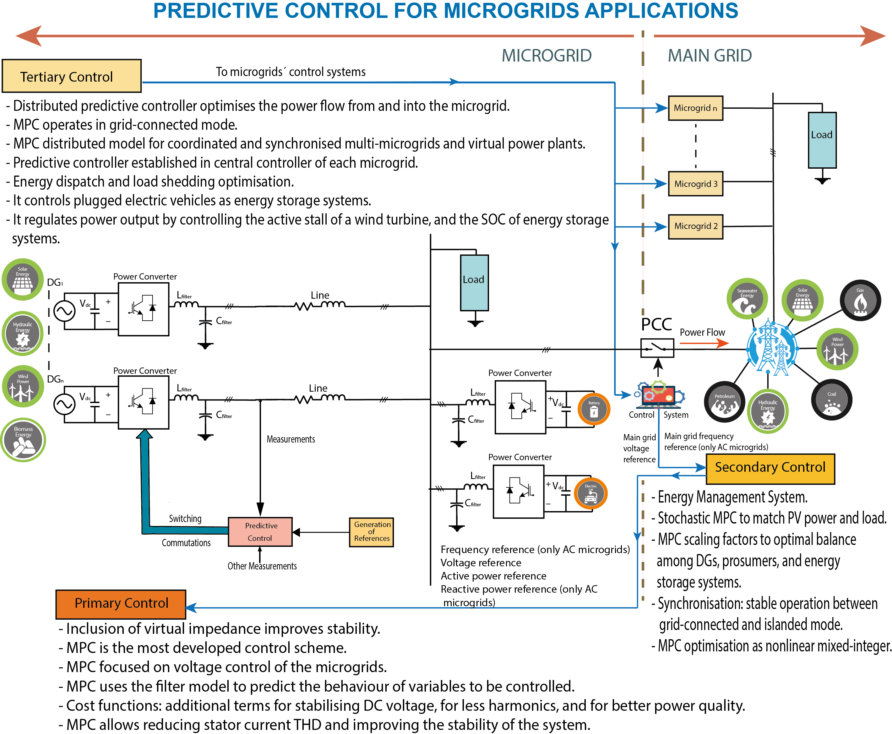
Currently, there has been a change in the way power systems are understood, due to the penetration of distributed generation that allows connecting smaller generators to low voltage networks (usually less than 1 kV) [1]. If the branches with distributed energy resources also contain loads, and in some cases, energy storage systems, the possibility of operating independently from the main grid can be considered. For instance, in the case of power shortages in the main grid, the branch with distributed generators, loads, and distributed energy storage systems can work isolated from the main grid. This microgrid needs to operate in a controlled and coordinated way, either grid-connected or in isolated mode [2]. In this context, it is possible to find three types of microgrids topologies, namely alternating-current (AC), direct-current (DC), and hybrid [3,4].
An AC microgrid consists mainly of distributed generators, loads, and energy storage systems connected to an AC bus commonly employed as the point of common coupling (PCC) with the main grid. In contrast, a DC microgrid is commonly designed for a distributed renewable energy source, energy storage systems, and DC loads, connected to the main grid via a bidirectional DC/AC converter for common integration [5,6]. Subsequently, a hybrid architecture includes AC and DC networks with AC and DC loads together with other typical components of a microgrid [4,7,8]. A typical structure of a microgrid with its components is depicted in Figure 1, where the control system works as an interface with the utility grid.
An important characteristic is that microgrids need control for the voltage and the active and reactive power [9]. Otherwise, they would just be branches of a distribution system. The microgrids appear in the general context of the utility grid as a controlled and coordinated unit [2].
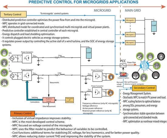
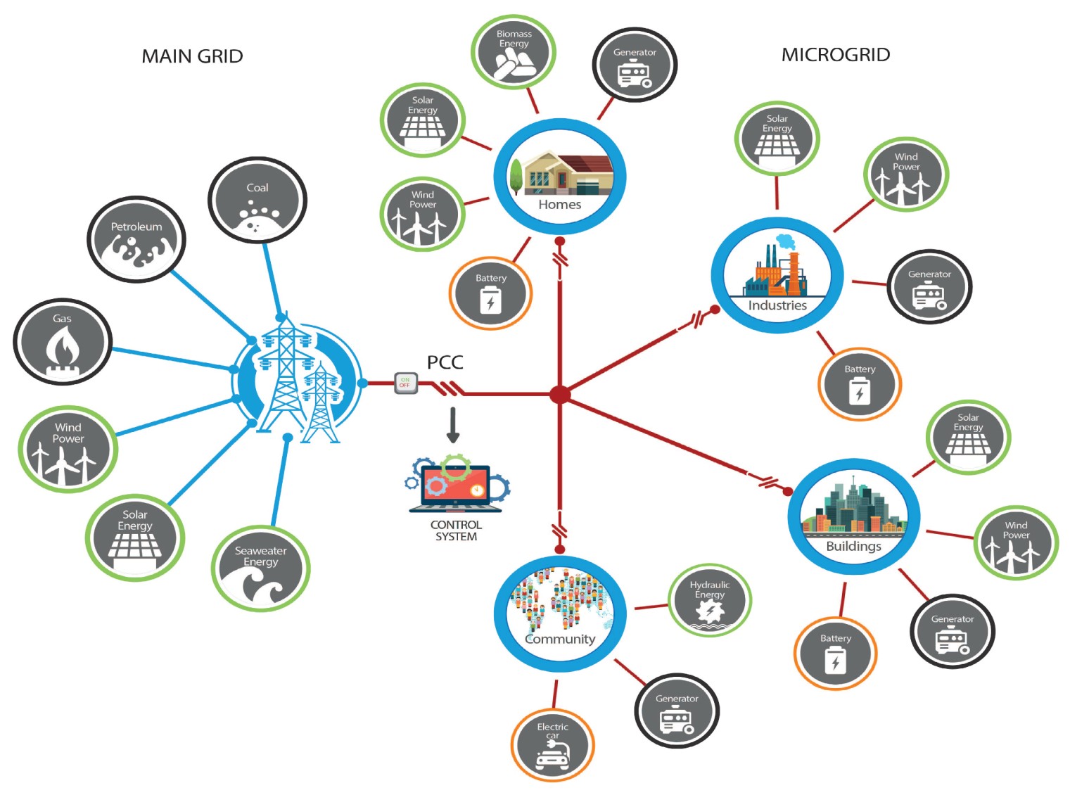
Control of a microgrid can be established at three hierarchical levels: primary, secondary, and tertiary, respectively (Figure 2). The control levels differ in their speed of response and the time frame in which they operate, as well as in infrastructure requirements, such as communication requirements [10]. Additionally, the control schemes can be established as centralised or decentralised.
The primary (local) level is related to individual components and local controls (distributed generators, energy storage systems, loads, and power electronics interfaces, meeting voltage and frequency references, islanding detection, power-sharing, and power generation control). The secondary level is in charge of load and renewable energy sources, load shedding/management, unit commitment/dispatch, secondary voltage/frequency control, secondary active/reactive power control, security monitoring, and black start. Finally, the upper or tertiary level is related to the market participation of microgrids, managing decisions for importing or exporting energy where a distribution network operator and a market operator can be found [3,10,11,12,13].
Power converters are used for microgrids’ primary control where renewable energy conversion systems have increased their participation as feasible and clean sources of energy. In photovoltaic generation systems, power converters are used for converting DC power to AC power in controlled and synchronised mode to the utility grid [13]. Furthermore, wind turbines can generate energy according to wind speed, which may be highly variable. Therefore, effective control of power converters is imperative and allows optimisation of the amount of energy extracted from the wind, fulfilling the main grid power quality standards and the microgrid’s performance [2,13].
For improving the quality and stability of microgrids, power converters play a paramount role. For instance, a power converter connected to a microgrid can inject the required current to compensate unbalance or harmonics created by nonlinear loads, avoiding thereby the distortion of the microgrid voltage [13,14,15].
In grid-connected mode, microgrids can both import energy from and export energy to the main grid. When seen from the standpoint of the microgrid, the main grid is considered as stiff; then, the microgrid has to take as given voltage and frequency levels [16]. In this operation, power converters are controlled to inject power as a function of the maximum power point tracking (MPPT) of the DGs [17,18,19,20]. In islanded mode, the microgrids’ operation is not affected by the main grid. Voltage and frequency levels are controlled by the DGs, using the voltage source converters (VSCs) as an interface. Thus, power-sharing among the DGs in an isolated microgrid has to deal with several aspects, for instance differences in line impedances, different voltage levels and local loads, among others [21]. The presence of circulating currents may be large and potentially damaging [22]. Several control techniques are focused on eliminating these circulating currents by power-sharing among power converters and considering differences in the line impedances [22,23,24]. Other techniques are developed to overcome these issues for microgrids’ control like the inclusion of virtual impedances that are added to modify the voltage reference that comes from the droop control in primary control [25]. Droop control delivers the voltage reference for inner controllers as the inner current and outer voltage feedback loop control. For those, classical control strategies for microgrids have been widely developed [11,26,27].
Microprocessors have undergone significant development in recent years, making the application of predictive control of power converters and electric drives feasible. There are several different approaches to develop a controller for power electronics using predictive control. A common feature shared by these approaches is the use of a model of the system to predict the future behaviour of the relevant and controlled variables. Later, a cost function is used to choose the proper actuation for the coming period [28].
Among the predictive control schemes for power converters are deadbeat control, generalised predictive control, and also model predictive control (MPC) with its variations, continuous control set and finite control [28,29,30].
Model predictive control has received extensive attention from researchers. It is now a well-established method for constrained control, having enough flexibility to include constraints and nonlinearities, including fast dynamic response and simplicity [31,32,33]. MPC includes principles of feedback control and numerical optimisation. As mentioned above, the development of microprocessors made possible their practical application despite the high computational demand, thus allowing their application to several areas, such as the control of thermal energy applications for buildings and HVAC systems [34].
- to develop a model where relevant and controlled variables are included;
- to minimise a cost function between reference and candidate values of controlled variables;
- to select the minimum difference to actuate for the coming period.
As there are several advantages of predictive control, there are also disadvantages. For instance, the finite control set model predictive control (FCS-MPC) results in a variable switching frequency as it does not consider the modulator. This results in noise and high voltage or current ripples in the power converter operation [36,37], affecting a wide spectrum, which decreases the power quality as the outcome [38,39]. To overcome these disadvantages, one solution could be the inclusion of modulation schemes in the optimisation algorithm [40]. FCS-MPC can also be modified to solve the variable switching frequency issue without using a modulator [41].
Referring to classical control strategies with microgrid applications, proportional-integral (PI) controllers are widely used in inner loop control. A PI controller consists of a transfer function that has and as its proportional and integral gain, respectively. The effectiveness of the PI controller can be improved by using a feed-forward voltage and/or cross-coupling term. Usually, a PI controller is implemented in the reference frame using a PLL, and its main advantage is that it achieves a zero steady-state error. Because of the latter, it is very useful for accurate real and reactive power flows in AC microgrids by directly controlling the real and reactive current components. One drawback is that it is not suitable to be applied in the presence of distorted electrical quantities [42,43]. Another classical control technique is the proportional-resonant (PR) controller, which can be applied in both the and reference frames. The steady-state error of electrical quantities can be easily eliminated since it has high gain near the resonant frequency [44]. Its two main drawbacks are that it needs accurate tuning and the sensitivity of frequency variations [43]. On the other side, hysteresis control approach is a very simple and fast response control scheme for current and voltage control. It produces a signal if the error between the reference and the measured signal exceeds certain given limits [45]. Its drawbacks refer to the output current ripple that may cause unacceptable THD levels and the difficulty to design the output filter owing to the randomness of its output [43]. All of these classical control strategies have been documented and developed to be applied to microgrids, but sometimes, there is a need for more advanced control techniques and others as MPC-based schemes, which permit more flexibility and the inclusion of several control objectives. Additionally, some of these classical control schemes, for instance PI control, do not have a very fast dynamic response as might be needed [18,27].
To deal with the necessity of fast dynamic responses in front of disturbances to ensure stability of the system, dealing with several control loop levels, among others, advanced control techniques may be applied to microgrids. For instance, in [46], the authors proposed a consensus-based distributed voltage control (DVC) for power-sharing in AC microgrids. One of the advantages of this control technique over MPC-based ones is that the latter do not involve the application to meshed microgrids, an architecture that can closely reflect a real application. Additionally, in [47], the authors proposed a robust control strategy for islanded AC microgrids that are comprised of several DGs. As will be seen, the surveyed papers in this work address mainly VSC-paralleled microgrids or smaller ones, with only a few DGs working together. Additionally, in [46], the proposed power-sharing control improved the performance for reactive power-sharing compared to voltage droop control.
The MPC-based techniques reviewed in this paper do not consider their operation along with droop control with significant changes, but rather to develop more detailed and improved models of the controlled systems and cost functions to be optimised for inner control. MPC-based controllers have the advantage of reflecting the intermittent nature of renewable energy sources, as those controllers may consider, for instance, stochastic and multi-variable control objectives. Classical control methods may no longer be effective to deal with this fluctuation, to ensure stable operation and high power quality [27]. Because of this, in [47], a two-degree-of-freedom feedback-feedforward controller was proposed to attenuate the impact of the disturbance signal on the system performance by regulating the load voltage irrespective of the load dynamics. On the other side, the disadvantages of an H-infinity controller () are the requirement of perfect mathematical understanding and relatively slow dynamics [43].
Another advanced algorithm to control the voltage of an AC microgrid is the so-called sliding mode control (SMC). It eases robust performance when there are variations of system parameters over wide ranges of operating points [43]. The authors in [48] proposed a decentralised sub-optimal second-order sliding mode control algorithm to regulate the microgrid voltage. The configuration of the controller is straightforward as it has a single control parameter, and there is no need for communication between the DGs of the AC microgrid, due to each controller using only local voltage information. Though it is a very easy-to-implement solution since it acts directly on the switches of the VSC, for more regular modulating signals, higher order sliding mode controllers can be applied by increasing the natural relative degree of the auxiliary system. On the other side, the MPC of power converters in microgrids is very intuitive and easy to implement, and the optimal actuation is selected and applied to the converter [28].
In [49], under the communication-based cooperative control paradigm, a distributed secondary/primary controller was proposed for DC microgrids. The secondary droop controller, which sets the voltage reference, is replaced by a voltage and a current regulator for each power converter. The local voltage set point is established by a noise-resilient voltage observer to estimate thus the global average voltage. The current regulator compares local per-unit current with its neighbours’ per-unit currents. Then, it adjusts the voltage set point to carry out proportional load sharing. The motivation was reducing dependence on output line impedance and avoiding poor performance of power-sharing (load sharing) [43]. Similarly, the authors in [50] used the so-called average voltage regulation to set point the voltage in a DC microgrid using the distributed control approach, to achieve simultaneously proper current sharing among the converters in the meshed DC microgrid, using dynamic resistive-inductive lines, and considering local measurements of generated currents and exchanged over a communication network. Similar approaches were developed in [51,52].
Finally, fuzzy-logic control (FLC) works as a form of numerous logic values and deals with reality, with linguistic values rather than crisp values. It ranges from one for completely true and zero for completely false. FLC is a class of nonlinear control techniques and the best among adaptive controllers. As power converters are nonlinear in nature, FLC can be used even without knowing the exact converter model and its parameters, having, though, proper robustness of the system. Nevertheless, this scheme can only achieve a good control performance with the heuristic reasoning-based expert knowledge of designers and precise control rules [18,43].
This work aims to review the application of predictive control on microgrids by considering the most relevant contributions in the last few years. The paper is organised considering the different levels of control of microgrids and separating the papers considering their architecture.
The rest of the paper is organised as follows: Section 2 reviews the applications to microgrids of several predictive control schemes and their variations, organised by control levels considering the microgrid architectures: AC, DC, and hybrid microgrids. Section 3 discusses the works surveyed that apply predictive control schemes to microgrids, and the conclusions of the work are given.
2. Predictive Control Strategies for Microgrid Applications
There is a wide family of controllers that can be included within the category of model predictive control [53]. These controllers have in common that they use a system model to predict the future behaviour of the variables up to a predefined time horizon and, as mentioned before, select the optimal actions by minimising a cost function [28].
The general form of the predictive model of the process behaviour corresponds to a discrete-time model, which can be expressed, for the sake of simplicity, as a state-space model in Equation (1) [28,29,53]:
where is the state vector of the system, is the vector of the inputs of the system, and is the vector of the outputs of the system, with the system matrix , the input matrix , and the output matrix . State-space models can be used for both single variable and multi-variable systems and also can be extended to nonlinear systems [53]. Then, the general form of the cost function, J, that represents the desired behaviour of the system can be defined by Equation (2). This equation considers the references, future states, and future actions [28,53].
MPC consists of an optimisation problem that aims to minimise the cost function J, for a predefined time horizon N, subject to the model of the system and its constraints. Thus, a sequence of N optimal actions is obtained since the controller will apply only the first element of the sequence shown in Equation (3). The optimisation problem is solved for each sampling instant again, with new measured data and the sequence of optimal actions [28,53].
In this section, the applications of predictive control to AC, DC, and hybrid microgrids according to the three hierarchical control levels are detailed. There are several trends in the publications surveyed referring to predictive control for microgrids applications. The main subjects found are detailed in the sections to come according to keywords related to the main topic: predictive control applied on microgrids.
2.1. Primary Control
This is also known as local or internal control and the first in the control hierarchy of the microgrid. It corresponds to the fastest response, which has to be based on local measurements with no communication [10]. Thus, it includes local protection as islanding detection, output control, and the subsequent change of controller modes [54].
Primary control is the control action by the local controller at the grid/load interfacing power electronics converters’ terminals. For AC microgrids, accurate active and reactive power-sharing among the DGs of the microgrid are among the main objectives of this control by incorporating the power controllers [55], as well as maintaining the VSC terminal voltage magnitude and frequency by using the voltage controllers and achieving the required filter inductor current by using the current controllers. MPC-based controllers are developed as linear controllers for current and voltage control. For DC microgrids, the primary local controllers typically include current, voltage, and droop control for each DG [43,56].
For hierarchical control of hybrid microgrid with power converters interfacing between AC and DC buses, decentralised control is exerted for voltage and current control. When the hybrid microgrid operates in autonomous mode, power-sharing between AC and DC microgrids cannot be achieved by conventional and droop controllers. However, the control for hybrids microgrids is more complicated due to the absence of a global variable that can be used for power-sharing and voltage and frequency regulation; the main primary control objectives remain the same as for AC microgrids and DC microgrids [56].
2.1.1. Primary Control of AC Microgrids
AC microgrids are built by two or more voltage source converters that must have the capability of regulating the voltage at the point of common coupling while sharing the load power at the same time. Finite control set MPC is used to replace the conventional hierarchical linear control loops and to overcome the limitations such as low transient response and high sensitivity to parameter variations. This control scheme is set to track explicitly the derivative of the voltage reference trajectory for a single voltage source converter, having a single step prediction horizon to diminish the computational effort considerably, reaching a steady-state performance and a very superior transient response and robustness to parameter variation when compared with hierarchical linear control.
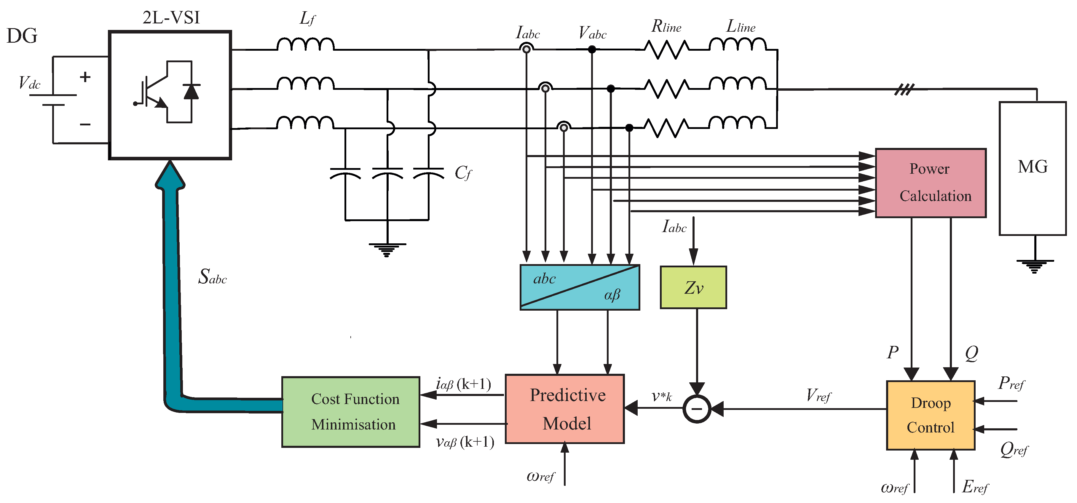
The AC microgrid’s model considers a two level three-phase voltage source converter (VSC) that feeds an output filter, which is connected to the AC microgrid through a line with an impedance . To implement the finite control set MPC, at the beginning of every sampling instant, new measurements are made of the filter capacitor voltage , the filter current , and the output current . Those measurements are the starting point from which the algorithm predicts the future path of the state variables and for every possible voltage vector. Their predicted values are then evaluated on a cost function for finding the vector that corresponds to its minimal value. The standard finite control set MPC presents problems to control the derivative of capacitor voltage, which is the main cause of high THD. Modifications of this conventional finite control set MPC to improve the VSCś capacitor voltage quality leads to the cost function in Equation (4) [12].
The term represents the capacitor voltage derivative trajectory. The difference between the reference voltage trajectory and the evaluated output voltage is minimised. The authors in [12] formulated this objective by Equation (5), with the filter capacitance , the grid angular reference , , and , the and components of the filter reference voltage, respectively, and , the and components of the filter current, respectively, and finally, and , the and components of the output current, respectively.
The term in the Equation (4) imposes the current constraint, while penalises the switching effort, which is proposed to be controlled by the weighting factor .
Finally, using the voltage regulation capability from the modified finite control set MPC scheme for controlling the converters expressed as the total cost function from Equation (4), in [12], the author could integrate the VSCs into the AC microgrid environment adding a virtual impedance loop and a direct droop control strategy to generate the voltage references. The proposed FCS-MPC scheme for the VSCs used in the AC microgrid can be seen in Figure 3.
2.1.2. Primary Control of DC Microgrids
When microgrids consider embedded generators, for instance solar photovoltaic or wind turbine, the primary control of those distributed generators is exerted by power converters, which for DC microgrids can have only a DC/DC or AC/DC stage, for solar and wind technologies, respectively.
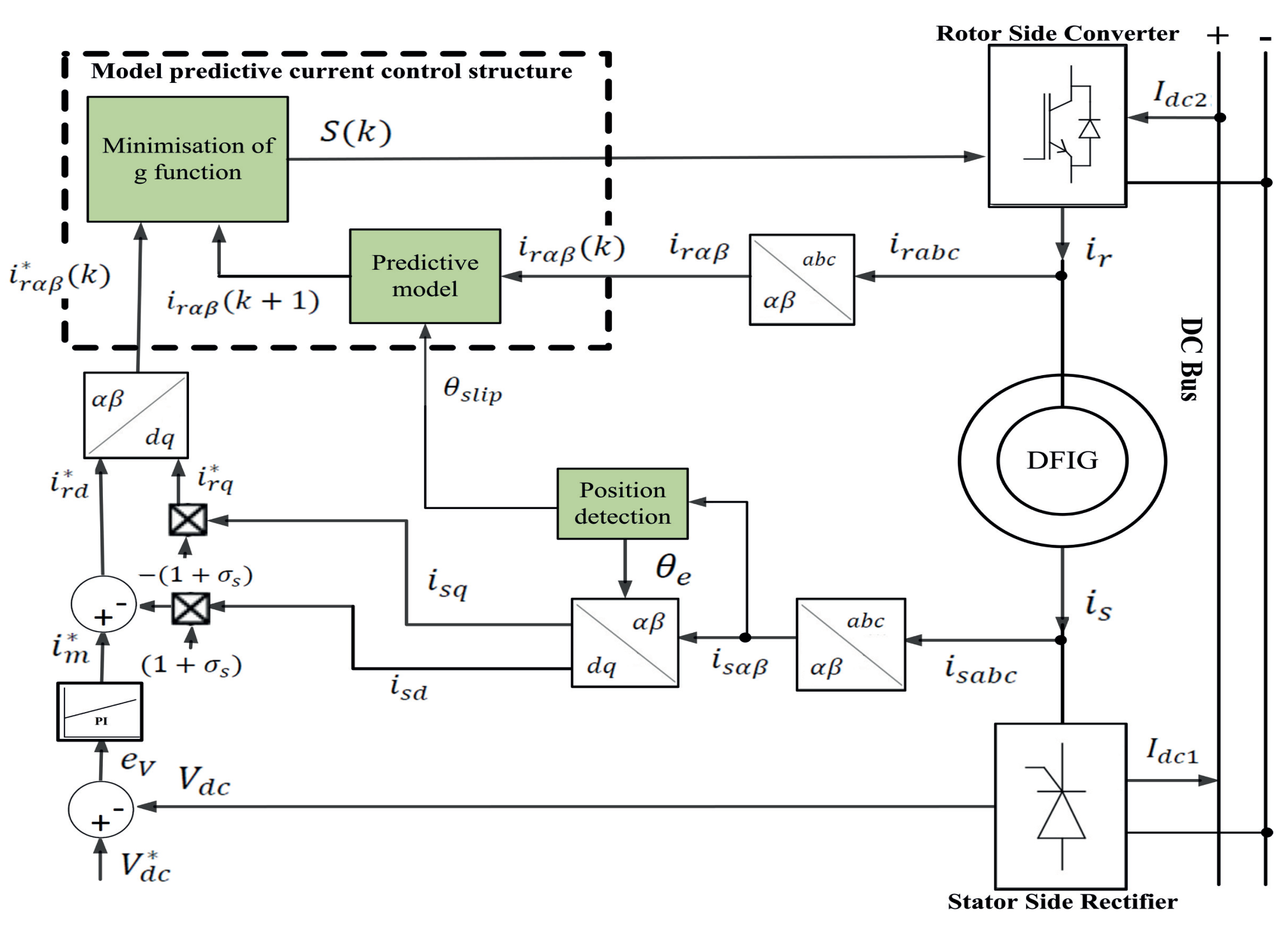
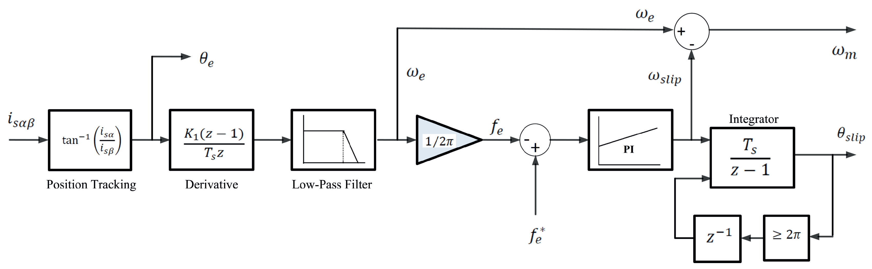
For the wind turbine with a doubly-fed induction generator (DFIG) shown in Figure 4, an application of current primary control is exerted by the voltage source converter that is connected to the rotor of the DFIG, which only has an AC/DC stage as it is connected to an DC microgrid that was developed in [57]. Here, a sensorless MPC strategy is used based on the frequency of the stator, obtaining a no-parameter-operation of the machine without a model, as shown in Figure 5. The sensorless technique first has to obtain the synchronous angular position , so the slip position signal can be estimated. is obtained as a function of the stator currents by Equation (6), where and are the reference frame components of the stator current.
Then, for finding the synchronous angular speed , over , a discrete-time approximation is applied, as presented in Equation (7), where is the synchronous angular speed at the current sampling time and and are the synchronous angular position at the current and previous sampling time, respectively. represents a scaling factor, which is determined as for this application, and is the sampling time,
After obtaining angular speed, the low-pass filter is applied, as seen in Figure 5, and the actual stator frequency can be computed using Equation (8).
As seen in Figure 5, a PI controller eliminates the error among actual and reference frequency ( Hz), and the output of the PI controller gives the slip angular speed , while a discrete-time integrator is used to obtain the slip angular position finally.
Finally, for establishing the MPC-based current controller for the rotor of the DFIG, two stages are commonly used: (1) a predictive model and (2) a cost function to be minimised. A discrete-time model of the DFIG is used for predicting the next sampling time behaviour of the rotor currents by Equation (9), where is the predicted rotor current vector at the next sampling time, the measured rotor current vector, the rotor resistance, the total leakage factor of the DFIG, the rotor self-inductance, the slip angular speed, the sampling time, the mutual inductance, the stator self-inductance, the measured stator flux vector, and the measured rotor voltage vector [57].
The result from minimising the cost function is used for determining the switching state of the VSC that is connected to the rotor, according to the reference and predicted rotor current values. Finally, the cost function (Equation (10)) to be minimised corresponds to the absolute rotor current error, so it is possible to minimise the error between the reference and the predicted rotor currents in the next sampling time [57]. In the cost function of Equation (10), and are the real and imaginary components of the predicted rotor current vector and and are the real and imaginary components of the reference current vector.
With the sensorless MPC strategy developed in [57], the cost of the power converter can be reduced. However, according to the authors, the THD of the stator current increases due to the nonlinear nature of the diode rectifiers. The MPC control scheme is used to overcome the weaknesses of the inner control loop and to improve steady-state performance and presents proper robustness.
On the other side, end-users connected to DC microgrids are considered as electronic loads that use point-of-load converters, which are in charge of conditioning power and regulating the voltage. Those loads can extract steady power even under varying voltage at the microgrid side behaving as constant power loads. These loads are seen as impedance with an incremental negative resistance. Thus, these point-of-load converters have a destabilising impact, which may cause large voltage oscillations, reaching even the possibility of having a blackout of the whole microgrid.
For the aforementioned, the authors in [58] presented an active damping method that introduces a stabilisation term in the cost function of the finite control set model predictive control scheme for regulating these point-of-load converters of a DC microgrid. The implementation of the finite control set MPC scheme considers the derivation of the converter model and design of the cost function. The considered converter corresponds to a two phase three phase voltage source converter whose discrete-time dynamic model on the AC side is as shown in Equation (11) and the discrete approximation of the behaviour of the DC link capacitor in Equation (12).
In Equation (11), is the inductor current, the capacitor voltage , the voltage vectors , and the output current . Regarding the time, represents the next sampling time to be predicted and the measured sampling time.In Equation (12), and are the initial and final currents flowing into the constant-point-of-load converter during the following time step, respectively, and is the sampling time [58].
Both Equations (11) and (12) predict the currents and the voltages in the AC side of the converter and the DC voltage at the end of the next sampling time. Those predicted values are introduced to evaluate the cost function, which determines the optimal actuation. The authors in [58] referred to the main cost function, already developed in Equation (5), which has the advantage of a term that allows better tracking of the derivative of the voltage reference, with being the angular frequency of the load reference voltage. This term is balanced into the cost function from Equation (5) with a weighting factor . The author in [58] included a current limiting term and a switching penalisation term . Then, the complete cost function that includes all the terms for the AC side voltage tracking is:
Using Equation (13) may lead to enforcing the converter to behave as a constant power load, making the DC microgrid performance unstable if there is a resonance in the output impedance of the power supply. The author proposed using first Equation (12) for solving the instability problem to predict the propagation of a DC voltage for every possible actuation. Then, the term that penalises the actions that may lead to deviations of the DC link voltage from its steady-state value is introduced by Equation (14) [58].
The result of Equation (14) s multiplied with weighting factor and added to the cost function from Equation (13) for forming the complete cost function that leads to stabilisation, finally, of the DC microgrid with point-of-load converters from end-users of electricity in the studied DC microgrid from [58]. Then, the complete cost function with the term that penalises the actions that lead to deviations of the DC link voltage is defined by Equation (15):
Adding the term in the cost function from Equation (15) allows better performance than state-of-the-art point-of-load converter-based stabilisation methods, making the system reach the steady-state almost immediately without ringing, in contrast with the more than 40 ms to reach the steady-state that the system took in [59].
Generalised predictive control as a part of MPC schemes is an option for controlling power converters, drives, and microgrids, which allows an analytical solution of the optimisation for the cost function, permitting an explicit control scheme that is straightforward to be implemented when the system is linear and has no constraints [60]. This control scheme was applied by [61] to control a single-phase quasi-Z-source inverter and combined with a linear controller in a DC microgrid as a method for power decoupling, e.g., to restrain the power ripple from avoiding the use of an unreliable and bulky electrolytic capacitor. The control is established as a multi-objective control, and the reduction of the low-frequency power ripple is achieved compensating by the voltage in the DC link of the inverter.
For generalised predictive control finding out the cost function and constraints to design the optimiser are paramount to ensure a good performance of the model. The generalised predictive algorithm used in [61] uses the discrete-time model as follows in Equation (16), where and are the k-step predicted values.
Then, the developed cost function in [61] is,
and the optimisation of the cost function is defined by Equation (18), where , , and as a control weighting factor for input variable difference. For this model, is considered as zero.
Once the derivative of Equation (18) is obtained, the minimisation of is known to give a state feedback control law in the form , but it can be rewritten by Equation (19), with and the steady-state values of the state and input variables, respectively.
The authors in [61] presented the following control law, which represents the optimiser block.
Finally, steady-state values are computed assuming the reference of the output variables as r and solving,
The algorithm presented in [61] for the generalised predictive control has two limitations. The first one is that steady-state accuracy depends on the references of the state and input variables from Equation (21), as it is difficult to obtain accurate commands for the input variables, for instance the duty cycle for power converters. The second one is that there is a preferred range for input variables like duty cycles. For instance, for buck converter would be [0, 1] where for boost converter would be [0.3, 0.7]. However, these constraints are not included in the optimiser when a generalised predictive control is used.
The authors in [61] used the generalised predictive control form of the MPC to control the SPQZSI in order to achieve power decoupling. To do this, two control objectives have to be considered in the scheme: the input current and the output current/voltage. In other words, input current has to be controlled, and the voltage capacitors have to be controlled within a range in accordance with the requirement of the output voltage. The authors mentioned that MPC was chosen because of its good expandability and constraint handling capability.
In an onboard DC microgrid that was analysed in [62], a current source converter (CSC) interfaces with an aircraft generator. To control the CSC with an output filter, a hybrid predictive control was developed. With a larger sampling time, a deadbeat predictive control was applied to the output circuit, generating reference source currents. With a smaller sampling time, an FCS-MPC was developed to control the input circuit to achieve sinusoidal source currents.
2.1.3. Primary Control of Hybrid Microgrids
In a hybrid microgrid studied in [63], composed by a a grid-interlinking front-end converter, a DC-bus that was fed by a 21 kWp PV system, a 10 kW wind energy generation system (WEGS), a 10 kW solid-oxide fuel cell, and a 20 ampere-hour lithium-ion battery energy storage system, to control the exchanged power among the front-end converter and the main grid and to track the maximum power point of the renewable energy generators, an artificial neural network was used. To control the PMSG-WEGS coupled with a AC-DC rectifier for interfacing with the DC-bus of the microgrid, a deadbeat predictive controller was used.
Deadbeat predictive control (also known as single-step predictive control) is one of the most well-known control techniques, being one of the first ones to be applied to power converters [64]. It uses the load and converter models to predict future behaviours for every sampling period. Its final actuation results in a fixed switching frequency, which is produced by the gating signals obtained by a PWM/SVM modulator that receives the most appropriate reference voltage vector [18]. Deadbeat predictive control uses a simple concept and does not involve any tuning or optimisation procedures, providing a superior performance for fast dynamic response compared with classical controllers, but having problems with system parameter variations and perturbations, measurement noise, and control delay, leading to instability issues [29].
The predictive torque control of the AC-DC converter used for the PMSG in [63] is used to improve the dynamic performance of the rectifier compared to the classical direct torque control scheme of the PMSG. The PMSG control system has to track the maximum power point of the wind turbine generator, to track the electromagnetic torque reference, and to maintain the direct stator current component close to zero. This scheme computes at each sampling interval the applied optimal stator voltage that minimises the cost function, at the next sampling interval, of the tracking errors between the predicted and references values for the voltage vector, for establishing the adequate switching pulses for the rectifier using a space-vector modulator. The model of the PMSG in the discrete-time in the synchronous rotating frame is defined by Equation (22).
Additionally, the linear relationship between the q-axis stator current and the generator torque can be expressed by Equation (23), with as the electromagnetic torque [63].
The deadbeat predictive principle applied in [63] tries to find the predicted values at the next sampling instant , these values being the generator torque and direct current component, which are equal to Equation (25).
As the d-axis current reference is considered with a zero value, it is assumed that the present set point of the d-axis current is equal to the future reference, based on [65],
2.1.4. Microgrid Stability in Primary Control
In [12], the author used a resistive virtual impedance loop to allow the output impedance coming from the VSCs of the AC microgrid, becoming resistive, to make it suitable for power-sharing of nonlinear loads and during transient conditions. The resistive virtual impedance loop adds damping to the system, favouring thus the microgrid stability. The resistive virtual impedance loop that can be seen in Figure 3 is implemented using Equation (31). The resulting control algorithm is extremely robust to parameter uncertainty, not losing stability even under high mismatch between the parameters used by the algorithm and the existing ones in the established proof-of-concept setup. It was mentioned there that other controllers always need to identify fairly conservative bounds for permissible parameter variations to ensure the stability of the system as is the case for repetitive control, for combined deadbeat and linear matrix inequality-based control, and for hierarchical linear control.
where is the resistive virtual impedance, is the filter capacitor voltage that is fed in the cost function, and is the voltage reference that comes from the outer droop control established in the FCS-MPC strategy applied in [12].
The stability issue in the microgrid system was addressed by [57] exerting rotational speed variations in the DFIG and load impacts in the DC microgrid. The results showed that during the speed acceleration, the estimated position signal tracked the real position signal with high accuracy in both sub-synchronous and super-synchronous speeds. To test the transient response of the sensorless MPC, the rotor current reference was changed. It was found that even with high-level THD, the transient time was very short, and the estimated slip position was properly tracking the real position. Finally, the steady-state and transient results of the proposed sensorless MPC technique indicated a good control performance under non-linear load condition.
In [58], the author introduced a stabilisation term in the cost function of the FCS-MPC algorithm that was used for regulation of the point-of-load converters in a DC microgrid. The method stabilises the system without implementing any additional active or passive components. Thus, higher energy efficiency and better cost-effectiveness can be achieved compared to active-passive component methods. This method is not focused on DC link stabilisation, affecting significantly less the load voltage regulation performance. The stabilisation term affects the output impedance of the point-of-load converter and the load voltage tracking performance. The stabilisation term is defined in Equation (14), and the resulting final cost function for the FCS-MPC algorithm is presented in Equation (15).
The authors in [61] developed a power decoupling method using SPQZSI in a DC microgrid. The system stability of the control scheme was analysed using Bode diagrams where it was seen that stability could be guaranteed with the designed control law and the predictor.
For a hybrid AC/DC microgrid with photovoltaic system, WEGS with PMSG, a fuel cell, and a energy storage system, the stability was tested by varying the solar cell temperature and noisy wind speed. As the WEGS is controlled by a deadbeat predictive control, it was proven that the predictive torque control of the AC-DC power converter for the PMSG helped to improve the dynamics performance. As variations on noisy wind speed were exerted, it was shown that the adaptive linear element-based speed controller ensured good control performance [63].
2.2. Secondary Control
The secondary control refers mainly to the management of the microgrid components [13]. Regarding this management and the conditions that these systems have to deal with, it is possible to ask about operating a microgrid with a high presence of renewable energy-based distributed generators, variable loads, and distributed energy storage systems, especially about how it can be operated in a coordinated manner as an efficient and reliable whole. The answer to this question may lie in the use of new approaches of predictive control applied to microgrids and the inclusion of uncertainties that are a part of the microgrids’ nature since renewable energy sources are intermittent and load demands vary throughout the day and the seasons of the year. They can be predicted for proper control of the microgrids.
In order to diminish the uncertainties and predict the proper operation, control schemes should include these uncertainties. The kind of microgrid control that may include these uncertainties is known as the energy management system or secondary control [13,66]. This is aimed to allow a reliable, secure, and economical operation of microgrids in either grid-connected or isolated mode. This task becomes especially challenging in isolated microgrids with the presence of highly variable renewable energy sources [10].
As will be seen, predictive control schemes are aimed to consider these uncertainties. At this microgrids’ control level, the model predictive control is applied using structures such as the predictive model, the optimisation model, and the control law [53].
The energy management system of the microgrid is responsible for power quality enhancement, restoring frequency and voltage in the microgrid due to primary level droop control actions [67]. For the case of DC microgrids, there is only voltage regulation [55]. Another secondary control objective is the re-synchronisation of the microgrid to the main grid and ensuring optimal and coordinated operation of DGs within the microgrid [67].
The frequency and voltage error deviations to produce control signals that are given by Equations (32) and (33), respectively, for the error correction that is sent to the primary controller in islanded mode, are processed by the secondary control [67],
where , , , and are the compensator closed-loop transfer functions and and are the terminal output voltage magnitude and its frequency at the common AC bus of the microgrid, with * denoting the reference value. and refer to correction in voltage magnitude and frequency, respectively, at the microgrid terminals [56].
2.2.1. Secondary Control of AC Microgrids
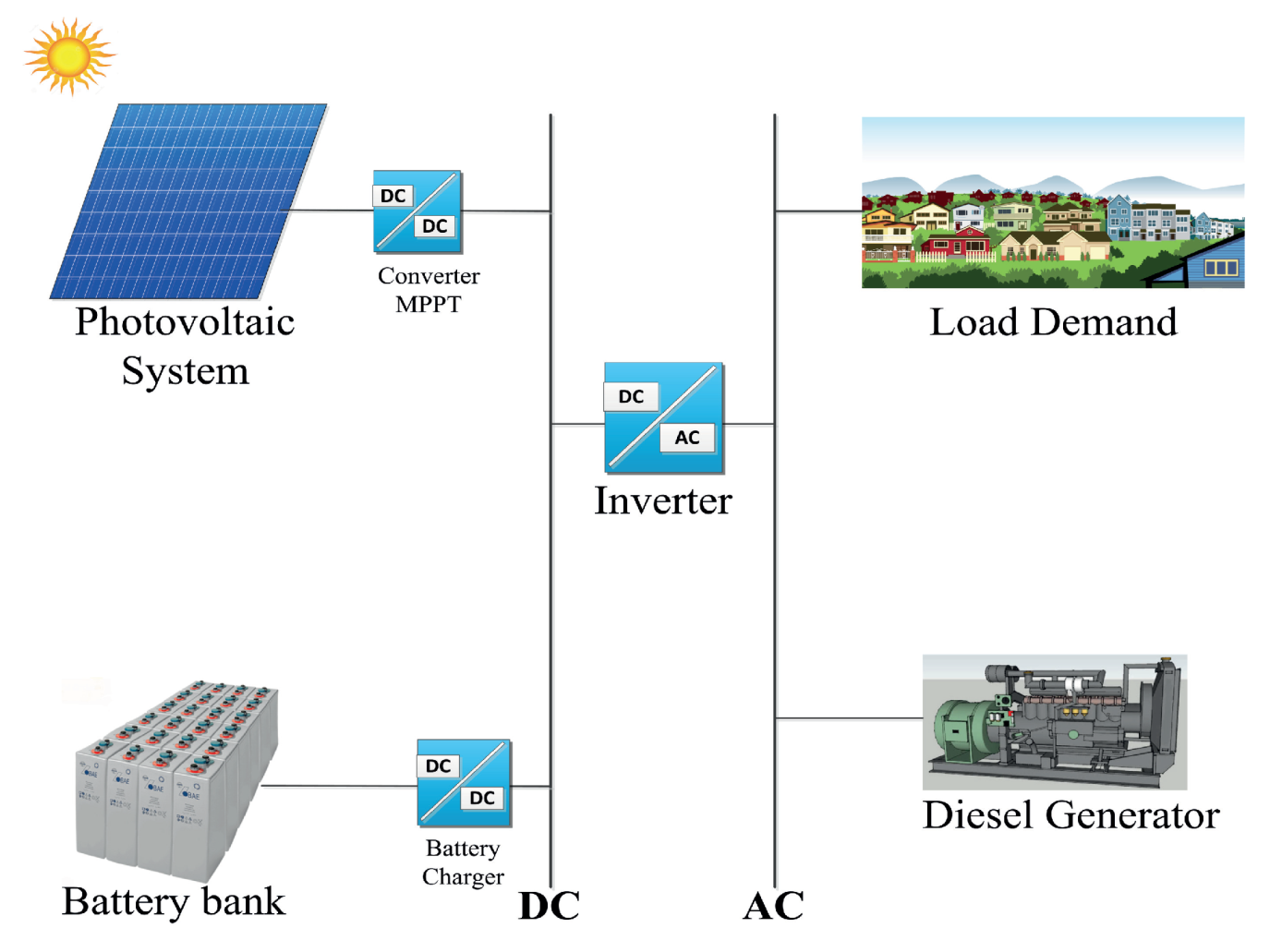
One of the main issues related to MPC is dealing with the short sampling times needed for the power electronics technology, as well as the robustness and accuracy of the model, both of which are improved with longer horizons. This issue may be dealt with using a combination of these horizons in predictive control. Thus, a two layer model predictive control may be used, with the two optimisation stages to be solved recursively for a long-term and short-term horizon. This scheme was applied by [68] to control an islanded AC microgrid, which worked on this mode permanently and composed by a photovoltaic system, a battery bank, and distributed diesel generators, as shown in Figure 6.
For the AC microgrid defined in [68], a two layer model predictive control was established that consisted of an optimal control problem for computing the power dispatch and a boundary value problem for the adjustment of the diesel generator start/stop time. This was to establish an advanced control strategy for its optimal operation. The control approach improves the robustness against uncertainties coming from the balance or unbalance that there may be between loads of energy demand and the photovoltaic power while minimising the operation cost. The aim of the optimisation problem is to minimise the operating cost of the energy system and to provide a constant energy supply, taking into account all the components of the microgrid. The optimisation problem is stated as a nonlinear mixed-integer optimisation problem by Equation (34), where and are the off-time vectors (combined start up/shutdown time) and the operation state (on/off) of the diesel generators, respectively [68].
For this islanded microgrid, the key factor for low-cost operation in the rural energy conditions is the minimisation of the diesel generator fuel cost, its running time, the optimisation of the battery usage, and the maximisation of the renewable share of the mix of energy sources from the microgrid [68]. This is expressed with the terminal stage cost defined by Equation (35).
The battery’s usage cost considers the cost for cycling 1 kWh through the battery and is dependant on the capital cost of the battery. The maximal depth of discharge and the cycle lifetime, considering, even, the replacement cost after the battery lifetime is reached and the battery DC bus voltage . Then, a transition cost is defined with the fuel consumption in it, a cost function for operation below 30% of the diesel generator power, the cost of the start-up/shutdown, and the operation and maintenance cost. The constraints of the model are related to the forecast load power, forecast PV power, the spinning reserve of the microgrid, and physical bounds for the operation limits of battery and diesel generator [68].
For solving the optimisation problem state as a nonlinear mixed-integer one for the microgrid shown in Figure 6, the two layer model predictive control is used and includes a discrete dynamic programming to help achieving the optimal solution in an acceptable time range. Thus, the model predictive approach determines the optimal operation for the energy system over 24 h ahead, e.g., for the next day forecast and updated during each iteration, based on the date the from previous day for the PV power and load demand, as this AC microgrid is an off-grid system installed in a remote area, due to the low-cost operation necessity. The model predictive control approach used is based on a recursive determination of the optimal operation of the optimisation established by Equation (35) and its constraints and the inclusion of the diesel generator start/stop time for adjustment as a boundary value problem.
In microgrids, energy storage systems play an important role in order to make power supply smoother and more continuous, absorbing energy demand when the generated power is not enough to supply the required energy by the loads. On the other hand, maintaining a high state of charge is essential for expanding the lifespan of any battery. For this purpose, a parallel comparison is made between a constant threshold model predictive control algorithm (CT-MPC) and a fit demand threshold model predictive control algorithm (ADT-MPC). Thus, the effectiveness of each method is assessed to decrease the demand charges ($/kW) as part of the time-of-use tariff program in addition to the cost of energy consumption ($/kWh), whereas the battery energy storage system is maintained with a high state of charge (SOC) during the microgrid’s operation.
MPC is used to establish an energy management system to control the batteries’ state of charge and the predicted solar power that is injected. Two different control schemes are compared for the lower energy demand and for maintaining, at the same time, a high state of charge of the battery energy storage during the system operation. The first scheme is a constant threshold MPC algorithm, and the second one adjusts that threshold according to the energy demand to carry the control out. As expected, the first scheme works better when there are accurate forecast models. The second one is better for highly variable systems [69].
Additionally, MPC can be established to apply second-level control of isolated microgrids, when there are deviations in the forecast of the availability of the renewable resource, using an integrated energy management system. The MPC solves discretely for each time interval to re-evaluate the dispatch decisions. This is based on the updated forecasted inputs and a moving time horizon, in order to have a better dispatch solution [70].
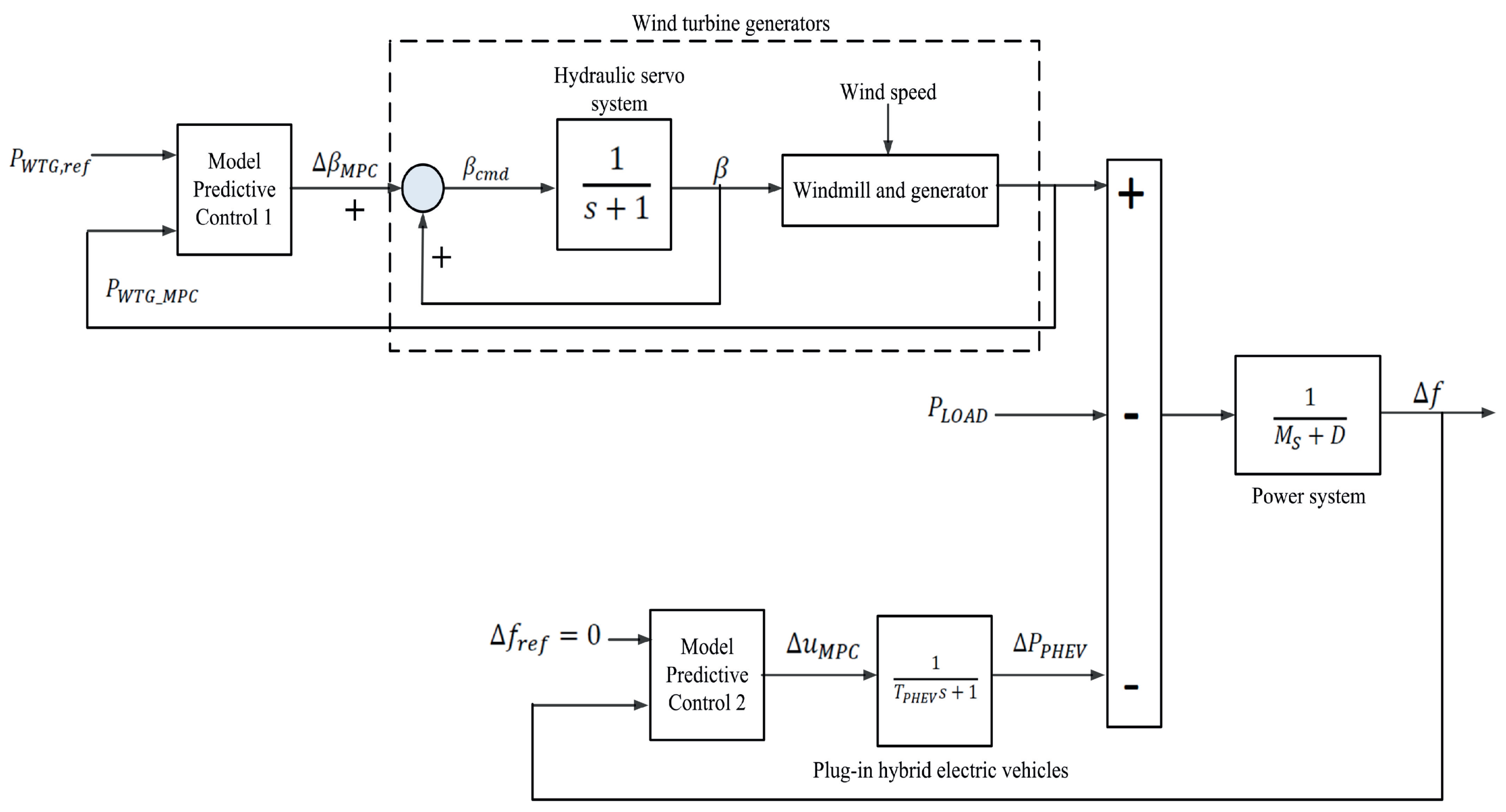
Another approach used for having an energy backup is the inclusion of plug-in hybrid electric vehicles as energy storage systems when they are in charging mode. MPC was developed in order to control the blade pitch angle of a wind turbine (that is active power control of the wind turbine with respect to the wind speed) and the load frequency of a microgrid, as shown in Figure 7. In this application, MPC aims to reduce the plug-in hybrid electric vehicles needed to smooth frequency fluctuation with the wind power production by pitch angle control [71].
The inclusion of renewable energy sources in microgrids brings opportunities, but also challenges, considering their intermittent nature. The microgrid components need to be managed efficiently. Uncertainties in the power supply have to be added to the predictive control of the microgrid, introduced by forecasting of the renewable power supply, also aiming to meet the consumer’s demand in an optimal, economic, and safe manner [72]. Predictive control can be modified for including these uncertainties, developing robust techniques. They are based on stochastic programming MPC, it being possible to use multi-scenario [73], tree-based [74], or chance-constrained model predictive control strategies [72,75].
Another application is to develop a stochastic programming based on an MPC in two stages for microgrid energy management under uncertainties of variable and random energy supply and loads. Stochastic programming in two stages cannot effectively deal with forecast uncertainties in a microgrid by itself. The risk from the impact of uncertainties, the intermittent renewable energy sources, and the load demand is minimised with an MPC strategy. This is used to avoid short sighting and further compensate these uncertainties within the microgrid by using a feedback mechanism [76].
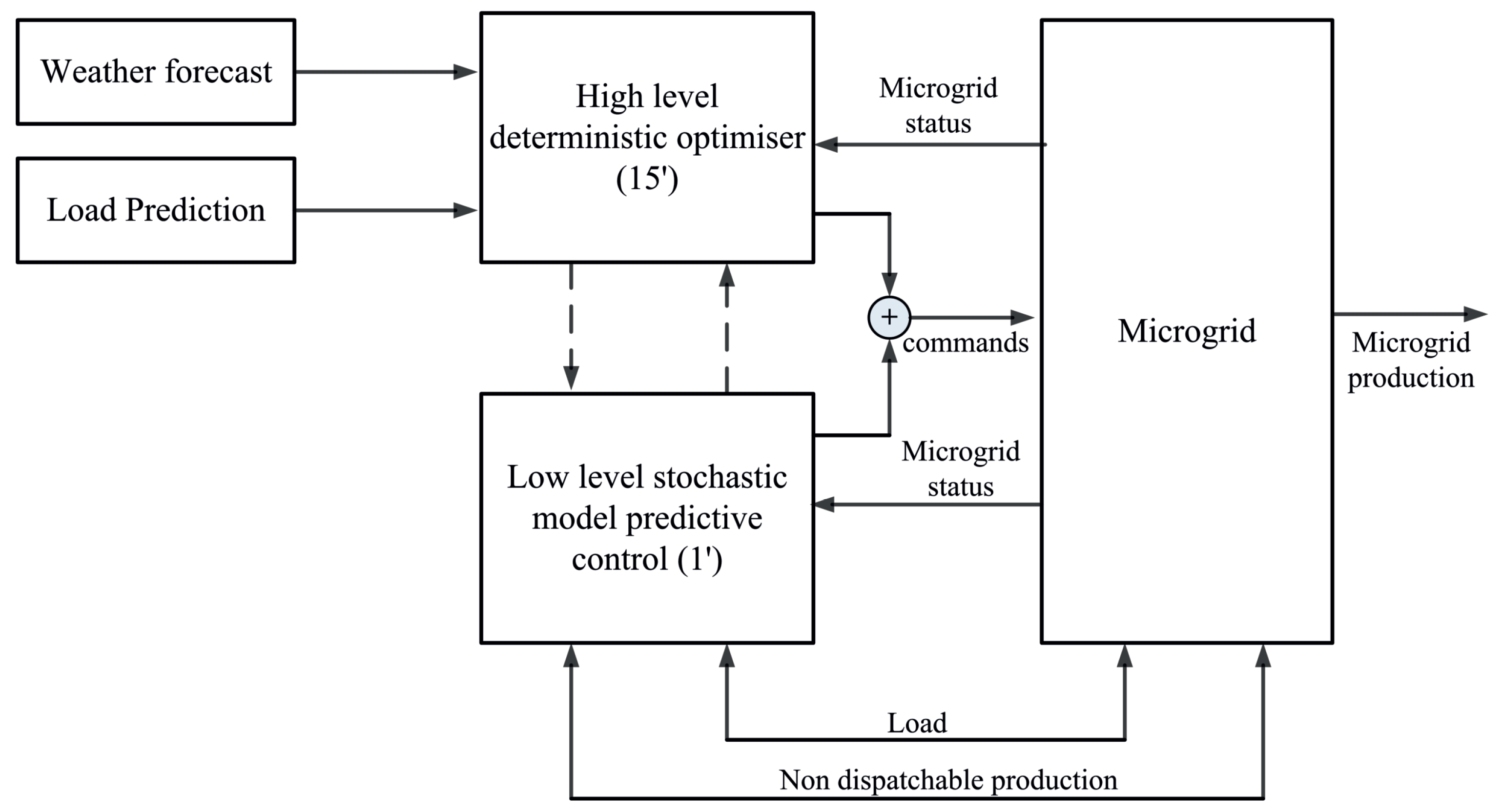
Another combination of sampling times (short and long horizons) using a two step MPC can be developed using a stochastic approach. The two different time scales are reflected in the functioning of a two level controller shown in Figure 8 with the low-level controller based on stochastic MPC. By using this scheme, the controllers run at different frequencies to adjust the AC microgrid operation. They minimise the difference, over each 15 minute interval, between the predicted energy exchange and the real energy generated, making the system avoid penalties [77].
The established stochastic MPC in [77] is to compensate for the disturbances on the load profile and on the power delivered by the photovoltaic system that is connected to the AC microgrid in a reactive fashion and to guarantee the fulfilment of the operational constraints.
Type-2 fuzzy models set a footprint of uncertainty. With this, upper and lower boundaries of the predicted values for wind power and load forecasting are established, provided by the established model, within the prediction interval with a certain confidence level. Adding probabilities to these values reflects the variability of the wind power and the load forecasting [78].
An isolated microgrid located in northern Chile with wind power generation has a control design based on a Type-2 fuzzy system. This is to deal with an important issue that is implied by being an isolated microgrid fed by wind energy: properly address the uncertainties associated with forecasted wind speed and the profile of the energy consumer. The energy management system developed was based on an MPC framework to diminish uncertainties in the forecasting available power and energy demand over a particular prediction horizon. At the same time, it minimised the cost of running the microgrid with a two day horizon in advance, supplying the necessary energy, keeping a balanced and synchronised microgrid [78].
The stochastic MPC approach is commonly used for the inclusion of uncertainties for optimisation of microgrid operation. This is done by formulating the control problem as a mixed-integer linear program [79] and min-max [80], among others [81].
The control of the microgrid operation considers, at the secondary control level, the inclusion of variable renewable sources and variable consumption demands. In the model established in [81], prosumer models were considered, where positive power injection to the microgrid means energy production. In contrast, negative power injection means energy consumption. Some prosumers are considered to be controlled by the established algorithm, i.e., their power flows are governed by the control signals, and others prosumers cannot be controlled. Additionally, power flows in the microgrid are modelled considering lossless lines, constant voltage magnitudes, and small phase differences between nodal voltages. The microgrid control was proposed, then, by using a tube MPC approach.
This scheme can give a specific answer to the question of how to incorporate uncertainties efficiently into the predictive control of microgrids. It consists of optimising the reference trajectory of the system over a fixed state and input constraints. A linear controller is used for keeping the real trajectory close to the reference values and introducing scaling factors for balancing disturbances’ compensation from different controllable components or subsystems of the microgrid, such as DGs, energy storage systems, and loads. The tube scaling MPC has to give a response to make the optimisation of the mixture among generators, storage units, and controllable loads, to supply the energy demand simultaneously in the microgrid, minimising the running costs of all constituent subsystems and satisfying the system inner constraints [81].
Another variation of the traditional predictive control schemes is the so-called distributed MPC in the discrete domain. This is used to define a particular cost function to each converter in the microgrid. As shown in [82], two level converters were controlled by this approach for exerting the secondary control of an AC microgrid. Each converter had its cost function to be minimised for finding the optimal control actuation.
An improved model predictive control is used to regulate the output voltage, frequency, and power of the inverters of a multi-microgrid. This multi-microgrid is composed by sub-microgrids separated from each other by about a 10 km transmission line. In the case of an islanding event, load voltage and frequency in the microgrid are affected. Nevertheless, these variables have to be kept running smoothly as much as possible. The inverters are configured to control the desired voltage, the frequency, the power, including the load shedding, as needed for keeping the stability of the multi-microgrid and each of their sub-microgrids. In this case, MPC is not dependent on the loads and line impedances of the multi-microgrid. Fast dynamic response and small steady-state error under different operating conditions can be achieved [83].
2.2.2. Secondary Control of DC Microgrids
DC microgrids with power micro-sources as wind turbines, energy storage systems, and connected to the main AC grid are interfaced with voltage source converters (VSCs) that include self-adaptive inertia control of the DC microgrid. This system was developed in the work in [84].
Thus, in the VSCs, a control scheme to add inertia to the DC microgrid is included to avoid undesired transition of converter operation mode or load shedding, during disturbances as sudden voltage sags in the system. The power converters are controlled with a MPC scheme that has as a voltage reference the value coming from the self-adaptive inertia control developed. The MPC scheme can provide rapid regulation of the power converter in front of system disturbances to control the proper power flow in the system. Thus, for instance, the MPC scheme for the VSC that interfaces with the WEGS takes the active power reference from the self-adaptive inertia control scheme. Similar control schemes are used for the VSCs that interface the AC main grid and the battery system [84].
The MPC strategy is applied for cooperating to have a rapid inertia adjustment strategy for the DC microgrid, to avoid control hysteresis and adjustment error. To avoid the control delay that may come using traditional vector control and the direct power control method based on deviation regulation, the MPC strategy for each VSC (in this case, the grid-side converter) uses the objective functions from Equation (36) and the system prediction model with the sampled system state variables at instant k to obtain the optimal control variable of each VSC at instant that fulfils the power fluctuation reduction and ensures system stability [84].
On the other hand, the electric spring is a scheme for stabilising voltages in the buses, being able to operate in an AC or a DC microgrid, to manage non-critical loads the way they are managed in smart grids like smart loads. Non-critical loads can be understood as appliances, which can support a wide range of voltage and power fluctuations [85].
A multiple DC electric spring generates reference voltages to control the DC voltage in the buses of DC microgrids with renewable energy distributed generators. This is done using a high-level centralised model predictive controller with non-adaptive weighting factors and adaptive weighting factors in order to extend the existing functions of the DC electric spring. This becomes very important if there is not enough energy storage capacity for offsetting voltage fluctuations in the buses of the DC microgrid [85].
In this DC microgrid, the critical loads can tolerate about 5% DC offsets, setting thus the bus voltage offsets. With this, the power flow is regulated by the control of the bus voltage. Then, the centralised MPC is used as a centralised MPC-based controller, using the following objective function [85]:
where is the nominal bus voltage of the DC microgrid; is the voltage tolerance of the critical loads by percentage; is the bus voltage with smart loads; is the weighting factor; means only the regulation of the bus voltage is concerned, and means only the power loss on the distribution lines is concerned.
2.2.3. Secondary Control of Hybrid Microgrids
It is very well known that renewable energy systems are intermittent. These fluctuating outputs and together with the variable power demand may deteriorate the voltage quality. In [27], an MPC strategy was developed to control a PV-wind-battery hybrid AC/DC microgrid. The microsources in the microgrid were interfaced with power converters: the energy storage system with a bidirectional buck-boost DC-DC converter, the PV system with a boost converter, and the WEGS with an AC-DC converter. The microgrid was composed of two parts: a DC subgrid with DC loads and an AC subgrid with AC loads. The AC and DC buses were interconnected through a bidirectional AC/DC interlinking converter, which corresponded to a three phase two level VSC. To control the bidirectional DC-DC converter that interfaced with the energy storage system, a model predictive current and power (MPCP) scheme was developed. To control the AC/DC interlinking converter, a model predictive voltage and power (MPVP) scheme was proposed. With these MPC-based schemes, both power converters were controlled coordinately to smooth the renewable energy outputs and for voltage control of the DC and AC buses. Finally, by considering fluctuating power generation, variable power demand, battery SOC, and electricity price, among others, a communication-based EMS was developed to ensure stable operation under grid-connected and islanded operation modes. The use of the MPC-based schemes allowed the DC bus to have less oscillations and overshoots with fluctuating power generation and consumption profiles. For the AC bus voltage, the MPC allowed better quality with less harmonic interferences.
2.2.4. Microgrid Stability in Secondary Control
In the work developed by [83], the MPC was established to regulate the output voltage, frequency, and power of the inverters of a multi-microgrid. In the case of an islanding disturbance event, those variables must remain stable. Using a centralised controller, the stability of the multi-microgrid system is ensured.
DC voltage is the indicator of system stability in DC microgrid. Keeping it stable implies having power balance of the system. In [84], the VSCs of the microgrid were controlled by MPC with the voltage reference value, which came from a self-adaptive inertia control. The DC microgrid contained VSCs for interfacing the WEGS, for the energy storage system, and for interfacing the main grid. The cost functions that were minimised for choosing the proper actuation were the ones shown in Equation (36), for the case of the grid-side VSC. The minimisation of these cost functions tried to reduce the power fluctuation, thus ensuring the system’s stability.
In the work developed in [85], the stability of the DC microgrid was regulated by controlling the DC bus voltage. In the objective function of the centralised MPC from Equation (37), the voltage tolerance for the critical loads in the DC microgrids was established. This voltage tolerance of the critical loads was generally stricter than the bus voltage tolerance in order to guarantee the stability of the analysed system.
2.3. Tertiary Control
Tertiary control is the highest control level and considers long-term and optimal operation of the microgrid in a particular energy market. This control is aimed to coordinate the operation of multiple microgrids interacting with each other in the system if this is the case [10].
In a projected future development of microgrids, they can be operated as multiple microgrids as they are composed of several low voltage microgrids and distributed generators connected to adjacent feeders [2,86,87].
The purpose of this tertiary control is to establish the power management by executing the power flow between the microgrid and the utility or main grid and the optimisation of the microgrid’s operation. This control coordinates and communicates, if that is the control scheme, the requirements such as voltage and frequency regulation from the main grid [10]. In this case, the power references are taken from the technical standards established for electric power grids from the distribution management system. The tertiary control processes and minimises the error between the measured and reference power values [56].
For the tertiary control of microgrids, applications of predictive control schemes were found only for the most studied AC microgrid. No publications for DC and hybrid microgrids were found.
For the works surveyed for this review paper, the MPC-based strategies at this level of control of microgrids are not focused on stability issues.
Tertiary Control of AC Microgrids
Microgrids can be considered as a unity of sub-microgrids to improve the efficient and economical operation of the multi-microgrid. MPC can be applied to control each sub-microgrid, resulting thereby in a distributed MPC scheme. This strategy optimises the cost function, considering other sub-microgrids at the same time. This application of MPC for multi-microgrids is a third level control strategy and considers economic operation, taking time-sharing price into consideration for maximising economic benefits based on energy sources and load prediction. For the latter, the distributed MPC scheme uses a centralised control approach for every sub-microgrid to realise the receding horizon optimal operation [86].
The logic of the established MPC strategy for the microgrid is that when it operates in grid-connected mode, the microgrid purchases electric power from the distributed network to maintain the frequency balance. At the same time, there is not enough output power supply from photovoltaic and energy storage sources to satisfy the load demands in the microgrid. Thus, there is power purchase cost in the line among the main grid and the microgrid, and an MPC-based energy management strategy can be implemented [86].
When the microgrid operates in autonomous mode, the control algorithm calculates the load demand to be matched with the predicted output from the energy storage system considering its constraints and the time the micro-sources in the microgrid can supply the load demand, optimising the microgrid operation [86].
Additionally, distributed MPC is applied to operate geographically distant distributed generators as a virtual power plant by a microgrid operator [2,88]. The authors of [88] developed a flexible, modular, and robust control architecture, which was based on the distributed MPC scheme. This algorithm, independently, establishes the optimal set points of the controllable DGs that are connected to the low-voltage AC microgrid. The algorithm works by optimising locally the control objectives, and besides, the coordination of the regulators allows the independent system operator (ISO) to act as a virtual power plant while providing ancillary services, as spinning reserve, voltage control, and black start [89], to the distribution system operator (DSO); with the day-ahead load predictions computed considering a cost performance index to the DSO, to diminish its uncertainties to act in the electricity market.
Optimisation of the energy dispatching for a microgrid connected to the main grid is carried out using a distributed MPC scheme. Here, the centralised mixed-integer programming problem of energy dispatching is converted into several interacting nonlinear programming problems and integer programming problems and a subsystem based on MPC, which are coordinated iteratively in order to minimise the cost over the entire system [90].
Power flow from the microgrid to the utility grid can be optimised, using a controller based on a mixed-integer linear program under an MPC framework. This optimisation of the power flow is an economic MPC approach for controlling microgrids [91]. Another approach can be executed in two stages, with the second stage having a model predictive control-based operation strategy of electric vehicle charging while parked, dealing with the uncertainty of parking behaviours within the real-time operation [92].
3. Discussion and Conclusions
3.1. Microgrids and Renewable Energy
Since the growth of the use of renewable energy resources and the installation of new renewable-based power plants is a global focus shift towards a sustainable society, with all the preplanned new installations, it is imperative to use renewable energy with the highest efficiency and reliability that technological advances can make possible [35].
With the introduction of distributed generation and microgrids, a revolution is occurring in the way power systems used to work, with not just power flowing from a generator to the final consumer, but in both directions, with electricity consumers also becoming energy active producers, known as prosumers in an energy market context [2,93,94].
Prosumers can reduce their energy costs by generating power when the marginal generation cost is lower than the price of electricity from the utility. They can sell the energy back to the grid, supplementing the grid power supply using clean renewable energy when there is abundant energy generation from these renewable sources and low-cost generators [95]. Microgrids, when they are connected to the utility grid through a PCC, may operate as a prosumer that has several distributed generators (DG) and controllable loads [2]. In this case, the tertiary level control operates to manage the power delivery from and to the microgrid and to optimise the economic dispatch from the DGs [96].
The developed predictive control schemes from [27] applied to the interfacing power converters in the hybrid microgrid allowed coordinated operation among the energy storage system and the AC subgrid through the AC/DC interlinking converter. To control the DC and AC buses voltages, the fluctuating renewable energy outputs are smoothed using the energy storage system controlled by the bidirectional DC-DC converter. It seems that controlling the energy storage systems, its SOC, and working operation modes helped to deal with fluctuating power from solar PV and wind energy generation system.
In order to use these distributed resources on small electrical grids, microgrids, power electronic conversion systems have led to a better and smoother coupling between these new distributed sources and loads, as well as the rest of the electrical grid [13]. Nevertheless, this ever-increasing penetration of power electronics in modern power systems is making them more complicated, where stability challenges, e.g., low inertia, multiple time scales, and the dynamics when power converters are connected to weak grids, appear as very important in terms of the control of the whole system [97].
It is clear that predictive control techniques applied to microgrids, at different hierarchical control levels, can play a very important role in dealing with the challenges of these more complex power systems and with the variable nature of renewable energy sources. One interesting aspect of the papers surveyed and focused on in model predictive control is the inclusion of uncertainties in the models for predicting, in this case power supply and power demand on a microgrid. These uncertainties are introduced in the MPC, making them stochastic based, mostly. These modifications to the control schemes are possible because predictive control offers flexibility and versatility in contrast with the classic control schemes, which are more rigid [10,18,28].
3.2. Primary Level Control
MPC presents several variations in order to improve its performance over microgrids systems. In [12], finite control set MPC was established as a very reasonable primary control option to improve the performance of power converter-based AC microgrids. Additional terms were added to the cost function, taking advantage of the flexibility that MPC has as a control scheme. On the other side, the same occurred with the added terms to the MPC’s cost function to improve DC link voltage stability in DC microgrids in the work developed by [58].
Additionally, MPC is used for controlling the operation of a DFIG of a wind turbine embedded in a DC microgrid with a simple, but effective approach that improves the steady-state performance with proper robustness [57]. The use of DFIG wind energy conversion systems has been very successful in the industry and academia [98,99,100], with several digital control techniques. DFIG can be controlled by field-oriented control (FOC), direct torque control (DTC), or direct power control with the reference frame fixed to a stator flux or voltage [101]. Then, MPC can be used instead of classical control schemes to improve control performance [18,102].
Regarding the application of the generalised form of the predictive control for microgrids, this kind of strategy results in a useful tool for establishing a proper multi-objective predictive control of a relatively new topology for a low power inverter (SPQZSI) and, thus, reduce harmonics and other power quality problems in microgrids, as was shown in [61]. As the usefulness of the SPQZSI is to improve the power quality, avoiding the low-frequency power ripple with small capacitance, conventional control lacks flexibility to include several control objectives. MPC in its generalised form plays an important role, allowing the fulfilment of the necessary control objectives of these sorts of power converters in microgrid systems.
In the paper [63], deadbeat predictive torque control was used for controlling a PMSG through a thyristor bridge where the dynamic performance of the predictive model could be improved compared to classical DTC, and a superior performance could be obtained. The main tasks of the deadbeat predictive control method are to track the maximum power point of the wind turbine generator instantaneously, to track the electromagnetic torque reference, and to maintain the direct stator current component close to zero. Nevertheless, the main objective of the work developed by the authors was the design and implementation of an online-trained artificial neural network-based control system for a hybrid microgrid. On the other side, deadbeat predictive control was used with large sampling times to generate the reference currents that enter the FCS-MPC, which finally controlled the CSC of an onboard aircraft DC microgrid [62]. Thus, the resulting hybrid predictive control scheme operated the CSC. This control scheme allowed eliminating the weighting factor, necessary to combine control objectives among the input and output circuits of the DC microgrid. The authors successfully proposed a control scheme with very low control complexity, which created the capability to operate with a high sampling frequency (up to 150 kHz).
At the primary level of control, the main control objectives of predictive control strategies refer to the stability of the system control, for realising voltage control, current control, power-sharing, and local protection in the microgrids [96].
3.3. Secondary Level Control
A high-level centralised technique for controlling the required DC voltages on a DC microgrid is used for improving the power quality by reducing the power loss in the distribution lines [85], applied to the secondary level of a microgrid. The centralised model predictive control is proposed with both non-adaptive weighting factors and adaptive weighting factors to further mitigate the power loss in the DC microgrid, with adaptive weighting factors being the best energy saver control strategy.
The control of power converters for dealing with wind variability as disturbances to the DC microgrid is aimed to control the stability in the whole system, a paramount aspect to be controlled in microgrid systems. As microgrids have a small inertial reserve if compared with utility grids, the role that the VSCs may play in the system stability is essential. To improve the inertial response, each converter of the microgrid is controlled using MPC. This control strategy was applied for cooperating to have a rapid inertia adjustment strategy to avoid control hysteresis and adjustment error, and not having control delay that classical control strategies may present [84].
The application of MPC as a secondary level controller of the AC microgrid under study in [77] was developed as a stochastic MPC, including inherent uncertainties to the intermittent nature of renewable energy sources and their dependence on the weather conditions. It is, indeed, for the secondary level of control that stochastic MPC is used more [13], for the necessity of having a stable and reliable source of electric energy, as the highest priority. The stochastic MPC algorithm developed in [77] allowed for the minimisation of the discrepancies with the optimal plan in the presence of stochastic disturbances that may appear in the photovoltaic power produced and in the load consumption versus the forecast values for those two variables in the microgrid. This technique allows the update of the high-level plan to redefine the nominal profiles according to the temporarily optimal solution. This enhances the performance of the microgrid system and contributes to compensating for any forecast error.
The use of tube scaling MPC of a microgrid includes stochastic variables to consider the nature of energy consumption and renewable energy-based DGs’ availability. With the inclusion of additional optimisation variables like scaling factors, the established algorithm permits an optimal balancing among disturbance compensation by the microgrid’s subsystems (DGs, prosumers, energy storage systems). The latter allows a robust optimal MPC-based control of the microgrid operation for voltage regulation in the microgrid system [81].
In the hybrid AC/DC microgrid developed in [27], an EMS was developed to ensure stable operation under different operation modes. Its effectiveness was validated based on a PV-wind-battery system with real-world solar and wind profiles, showing better control capability and improved voltage quality. Nevertheless, to establish the EMS, communication facilities are needed, and at level of the power converters, additional measurements need to be considered if compared with traditional cascade PID controllers.
At the secondary level of control, the main control objectives refer to the power quality control, with the development of mathematical models to predict and optimise the actuation for frequency regulation, voltage regulation, and synchronisation with the main grid [96].
3.4. Tertiary Level Control
MPC is applied on a distributed model for optimising the function of the different distributed generators in several microgrids to work coordinated and together, allowing the independent system operator to manage the different microgrids as multi-microgrids and as virtual power plants. According to the authors, the energy management system was based on a distributed algorithm, which considered time-sharing price among the microgrids that composed the multi-microgrid and the distributed network of the main grid. For autonomous functioning of the multi-microgrid, a multi-objective function based on source-load prediction and using receding optimisation to solve it for each microgrid central controller permitted the optimal operation in the multi-microgrid without purchasing electric power from the main grid and fulfilling the constraints related to power availability coming from photovoltaic and energy storage systems [86].
The development of distributed predictive controllers allows coordinating inside a microgrid the energy dispatch optimisation, the load shedding, and the use of the electric vehicles when charging as storage systems [88,90,91,92].
MPC is applied to an energy management system for a microgrid in order to control the state of charges of battery energy storage [69] and to another one that works in isolated mode to control the power output of a wind turbine by active stall (change of the blade pitch angle of the wind turbine) and the functioning of plug-in hybrid vehicles as energy storage systems [71].
At this tertiary level of control, the main control objectives refer to the power flow control, with the development of mathematical models to predict and optimise the microgrid operation when it is in grid-connected mode, establishing, thus, power management and economic dispatch strategies [96].
3.5. Predictive Control Trends
Among the control techniques of power converters and electrical drives, MPC is one method that is gaining great popularity [35]. Consequently, it has agglutinated the most significant amount of research and publications related to its application on microgrids, with some variations of the original predictive control.
In general, MPC is applied to local control and protection, the control of the microgrid, and for the upstream network interface [13], thus encompassing the three hierarchical control levels of a microgrid [10].
Additionally, predictive control is comprised of several methods that are used in power electronics, with MPC being very promising and having significant potential and versatility for controlling microgrids in their three control levels, when necessary.
The investigation of microgrids has increased in the last few years, as well as the research on their control. Furthermore, microgrid control is comprised of the technical feasibility functioning of each distributed generator, energy storage unit, and the loads of the microgrid (primary control), the feasibility of running the whole system from a power quality point of view (secondary microgrid control), as well as the technical and economical feasibility of the microgrid in an electrical market context (tertiary control).
It is at each of the control levels where power converters and electrical drives play an important role. These devices have to fulfil a determined objective of control since the strategies applied for controlling them are paramount when establishing and operating a microgrid.
In this way, predictive control schemes have several applications to microgrids, with advantages compared with other control strategies: intuitive and easy to understand; flexible to apply to different power converter topologies and situations, allowing the inclusion of constraints and nonlinearities; control of several variables at the same time; and for considering uncertainties when renewable energy sources are embedded into microgrids.
MPC strategies may present, in some cases, a lack of robustness in front of unavoidable modelling uncertainties and external disturbances that affect the controlled systems. Regarding this, all the surveyed works included some new techniques to overcome this disadvantage. These techniques considered the following: the inclusion of new terms in the cost function; the addition of a modulation stage for inner control; its combination with advanced novel control techniques as fuzzy-logic control and artificial neural network control; the combination of different MPC-based schemes for a system with multi-variable control objectives, to avoid heuristic selection of weighting factors.
The aforementioned aspects prove the versatility and flexibility of the MPC-based family of controllers when applied to power converters, drives, and to power-electronics-controlled microgrids with a high inclusion of renewable energy-based DGs. These predictive control methods permit proper operation of microgrids under different modes and under external disturbances. Furthermore, at the tertiary level, MPC permits efficient power management and an economic dispatch under electricity market conditions.
In this work, MPC presented the most significant amount of research associated with microgrid application, as it considered several variations and improvements to the basic model, for instance stochastic-based MPC, represented as a different control, but with the same bases, highlighting the importance of this technique.
Regarding AC, DC, and hybrid microgrid topologies and the application of predictive control, it was found that AC microgrids have had larger development, especially in the secondary control level. Furthermore, for DC microgrids, although there was less development, primary and secondary control had several applications that used predictive control schemes. Hybrid microgrids presented fewer applications of predictive control schemes, and the application found was aimed at carrying out a primary control.
In a world that requires cleaner and more reliable electric power grids, variable renewable sources are more and more integrated as embedded generation with the necessity of overcoming their variability for accurate and robust predictions for proper control. It clearly appears that the inclusion of uncertainties introduced by renewable source-based distributed generators is essential and a trend in the research for developing proper control of microgrids using predictions of power supply and demand in advance.
Author Contributions
Conceptualisation, A.V., M.R., Y.S. and J.M.; methodology, A.V. and M.R.; software, A.V.; validation, M.R., T.D. and F.B.; formal analysis, A.V.; investigation, A.V.; resources, A.V., M.R. and J.M.; data curation, A.V., M.R. and Y.S.; writing—original draft preparation, A.V.; writing—review and editing, A.V., M.R. and Y.S.; visualisation, A.V.; supervision, M.R., J.M., T.D. and F.B.; project administration, M.R. and J.M.; funding acquisition, M.R. and J.M. All authors have read and agreed to the published version of the manuscript.
Funding
This research was funded by the Agencia Nacional de Investigación y Desarrollo (ANID) FONDECYT Regular grant numbers 1191028 and 1160690.
Acknowledgments
The authors thank the support of the CONICYT PFCHA/Doctorado Becas Chile/2019—21190255 and the ANID/FONDECYT Programme through Regular 1191028 and Regular 1160690.
Conflicts of Interest
The authors declare no conflict of interest.
Abbreviations
The following abbreviations are used in this manuscript:
| AC | Alternating current |
| DC | Direct current |
| PCC | Point of common coupling |
| MPC | Model predictive control |
| HVAC | Heating ventilation air conditioning |
| VSC | Voltage source converter |
| PI | Proportional-integral |
| PR | Proportional-resonant |
| PLL | Phase-locked loop |
| DVC | Distributed voltage control |
| SMC | Sliding mode control |
| H-infinity control | |
| FLC | Fuzzy-logic controller |
| FCS-MPC | Finite control set-model predictive control |
| THD | Total harmonic distortion |
| DFIG | Doubly-fed induction generator |
| SPQZSI | Single-phase quasi-Z-source inverter |
| CSC | Current source converter |
| PWM | Pulse-width modulation |
| SVM | Space vector modulation |
| PV | Photovoltaic |
| WEGS | Wind energy generation system |
| PMSG | Permanent magnet synchronous generator |
| CT-MPC | Constant threshold model predictive control |
| ADT-MPC | Adjusting demand threshold model predictive control |
| SOC | State of charge |
| DG | Distributed generator |
| FOC | Field-oriented control |
| DTC | Direct torque control |
| MPCP | Model predictive current and power |
| MPVP | Model predictive voltage and power |
| EMS | Energy management scheme |
| DSO | Distribution system operator |
| ISO | Independent system operator |
References
- Jenkins, N.; Allan, R.; Crossley, P.; Kirschen, D.; Strbac, G. Embedded Generation, reprinted ed.; Institution of Engineering and Technology: Milton Keynes, UK, 2008; p. 273. [Google Scholar]
- Schwaegerl, C.; Tao, L. The microgrids concept. In Microgrids: Architectures and control, 1st ed.; Hatziargyriou, N., Ed.; Wiley-IEEE Press: Chichester, UK, 2014; pp. 1–24. [Google Scholar]
- Planas, E.; Gil-de Muro, A.; Andreu, J.; Kortabarria, I.; de Alegría, I.M. General aspects, hierarchical controls and droop methods in microgrids: A review. Renew. Sustain. Energy Rev. 2013, 17, 147–159. [Google Scholar] [CrossRef]
- Unamuno, E.; Barrena, J.A. Hybrid ac/dc microgrids—Part II: Review and classification of control strategies. Renew. Sustain. Energy Rev. 2015, 52, 1123–1134. [Google Scholar] [CrossRef]
- Chen, D.; Xu, L. AC and DC microgrid with distributed energy resources. In Technologies and Applications for Smart Charging of Electric and Plug-in Hybrid Vehicles, 1st ed.; Veneri, O., Ed.; Springer: Cham, Switzerland, 2017; Chapter 2; pp. 39–64. [Google Scholar]
- Justo, J.J.; Mwasilu, F.; Lee, J.; Jung, J.W. AC-microgrids versus DC-microgrids with distributed energy resources: A review. Renew. Sustain. Energy Rev. 2013, 24, 387–405. [Google Scholar] [CrossRef]
- Yongqiang, Z.; Tianjing, W. Comparison of centralised and distributed energy storage configuration for AC/DC hybrid microgrid. J. Eng. 2017, 2017, 1838–1842. [Google Scholar] [CrossRef]
- He, J.; Du, L.; Liang, B.; Li, Y.; Wang, C. Coupled-Virtual-Impedance Control for AC/DC Hybrid Microgrid Power Electronic Interlinking Unit with Dual Converters. IEEE Trans. Smart Grid 2018, 3053, 1. [Google Scholar]
- Jiang, Z.; Yu, X. Active power—Voltage control scheme for islanding operation of inverter-interfaced microgrids. In Proceedings of the 2009 IEEE Power and Energy Society General Meeting, PES ’09, Calgary, AB, Canada, 26–30 July 2009; pp. 1–7. [Google Scholar]
- Olivares, D.E.; Mehrizi-Sani, A.; Etemadi, A.H.; Cañizares, C.A.; Iravani, R.; Kazerani, M.; Hajimiragha, A.H.; Gomis-Bellmunt, O.; Saeedifard, M.; Palma-Behnke, R.; et al. Trends in microgrid control. IEEE Trans. Smart Grid 2014, 5, 1905–1919. [Google Scholar] [CrossRef]
- Han, H.; Hou, X.; Yang, J.; Wu, J.; Su, M.; Guerrero, J.M. Review of power sharing control strategies for islanding operation of AC microgrids. IEEE Trans. Smart Grid 2016, 7, 200–215. [Google Scholar] [CrossRef] [Green Version]
- Dragicevic, T. Model Predictive Control of Power Converters for Robust and Fast Operation of AC Microgrids. IEEE Trans. Power Electron. 2018, 33, 6304–6317. [Google Scholar] [CrossRef]
- Dimeas, A.; Tsikalakis, A.; Kariniotakis, G.; Korres, G. Microgrids control issues. In Microgrids: Architectures and Control, 1st ed.; Hatziargyriou, N., Ed.; Wiley-IEEE Press: Chichester, UK, 2014; pp. 25–80. [Google Scholar]
- Degner, T.; Soultanis, N.; Engler, A.; Gil de Muro, A. Intelligent local controllers. In Microgrids: Architectures and Control, 1st ed.; Hatziargyriou, N., Ed.; Wiley-IEEE Press: Chichester, UK, 2014; pp. 81–116. [Google Scholar]
- Hatziargyriou, N.; Asano, H.; Iravani, R.; Marnay, C. Microgrids. IEEE Power Energy Mag. 2007, 5, 78–94. [Google Scholar] [CrossRef]
- Peng, Z.; Wang, J.; Bi, D.; Wen, Y.; Dai, Y.; Yin, X.; Shen, Z.J. Droop control strategy incorporating coupling compensation and virtual impedance for microgrid application. IEEE Trans. Energy Convers. 2019, 34, 277–291. [Google Scholar] [CrossRef]
- Rocabert, J.; Luna, A.; Blaabjerg, F.; Rodríguez, P. Control of Power Converters in AC Microgrids. IEEE Trans. Power Electron. 2012, 27, 4734–4749. [Google Scholar] [CrossRef]
- Yaramasu, V.; Wu, B. Model Predictive Control of Wind Energy Conversion Systems, 1st ed.; IEEE Press-Wiley: Chichester, UK, 2017; p. 467. [Google Scholar]
- Muñoz, C.; Rivera, M.; Villalón, A.; Riveros, J.; Muñoz, J.; Wheeler, P. Predictive Control for MPPT in a Single-Stage Photovoltaic System. In Proceedings of the 2018 IEEE International Confer Proceedings of the 2018 IEEE International Conference on Electrical Systems for Aircraft, Railway, Ship Propulsion and Road Vehicles and International Transportation Electrification Conference, ESARS-ITEC 2018, Nottingham, UK, 7–9 November 2019; pp. 1–6. [Google Scholar]
- Villalón, A.; Muñoz, C.; Muñoz, J.; Rivera, M.; Sarbanzadeh, M.; Hosseinzadeh, M.A. Control of a three-phase cascaded h-bridge multilevel inverter for solar energy injection. In Proceedings of the IEEE International Conference on Industrial Technology, Nottingham, UK, 7–9 November 2019; Volume 2019, pp. 399–404. [Google Scholar]
- Andishgar, M.H.; Gholipour, E.; Hooshmand, R.A. An overview of control approaches of inverter-based microgrids in islanding mode of operation. Renew. Sustain. Energy Rev. 2017, 80, 1043–1060. [Google Scholar] [CrossRef]
- Holvik, A.B. Virtual Impedance Techniques for Power Sharing Control in AC Islanded Microgrids. Master’s Thesis, Norwegian University of Science and Technology, Trondheim, Norway, 2018. [Google Scholar]
- Augustine, S.; Mishra, M.K.; Lakshminarasamma, N. An Improved Droop Control Algorithm for Load Sharing and Circulating Current Control for Parallel DC-DC Converters in Standalone DC Microgrid. In Proceedings of the 2014 Annual International Conference on Emerging Research Areas: Magnetics, Machines and Drives (AICERA/iCMMD), Kottayam, India, 24–26 July 2014; pp. 1–6. [Google Scholar]
- Zhang, M.; Song, B.; Wang, J. Circulating Current Control Strategy Based on Equivalent Feeder for Parallel Inverters in Islanded Microgrid. IEEE Trans. Power Syst. 2019, 34, 595–605. [Google Scholar] [CrossRef]
- Villalón, A.; Muñoz, C.; Aliaga, R.; Muñoz, J.; Rivera, M.; Zanchetta, P. Power Sharing Control of Islanded AC Microgrid Considering Droop Control and Virtual Impedance. In Proceedings of the 2020 IEEE International Conference on Industrial Technology (ICIT), Buenos Aires, Argentina, 26–28 February 2020; pp. 1139–1144. [Google Scholar]
- Han, Y.; Li, H.; Shen, P.; Coelho, E.A.A.; Guerrero, J.M. Review of Active and Reactive Power Sharing Strategies in Hierarchical Controlled Microgrids. IEEE Trans. Power Electron. 2017, 32, 2427–2451. [Google Scholar] [CrossRef] [Green Version]
- Shan, Y.; Hu, J.; Chan, K.W.; Fu, Q.; Guerrero, J.M. Model Predictive Control of Bidirectional DC–DC Converters and AC/DC Interlinking Converters—A New Control Method for PV-Wind-Battery Microgrids. IEEE Trans. Sustain. Energy 2019, 10, 1823–1833. [Google Scholar] [CrossRef]
- Rodríguez, J.; Cortés, P. Predictive Control of Power Converters and Electrical Drives; Wiley-IEEE: Chichester, UK, 2012; p. 231. [Google Scholar]
- Cortés, P.; Kazmierkowski, M.; Kennel, R.; Quevedo, D.; Rodriguez, J. Predictive Control in Power Electronics and Drives. IEEE Trans. Ind. Electron. 2008, 55, 4312–4324. [Google Scholar] [CrossRef]
- Kennel, R.; Linder, A.; Linke, M. Generalized predictive control (GPC)-ready for use in drive applications. In Proceedings of the 2001 IEEE 32nd Annual Power Electronics Specialists Conference, Vancouver, BC, Canada, 17–21 June 2001; Volume 4, pp. 1839–1844. [Google Scholar]
- Vazquez, S.; Leon, J.I.; Franquelo, L.G.; Rodríguez, J.; Young, H.A.; Marquez, A.; Zanchetta, P. Model predictive control: A Review of Its Applications in Power Electronics. IEEE Ind. Electron. Mag. 2014, 8, 16–31. [Google Scholar] [CrossRef]
- Hosseinzadeh, M.A.; Sarbanzadeh, M.; Sarbanzadeh, E.; Rivera, M.; Gregor, R. Recent Challenge and Trends of Predictive Control in Power Electronics Application. In Proceedings of the 2018 IEEE International Conference on Electrical Systems for Aircraft, Railway, Ship Propulsion and Road Vehicles and International Transportation Electrification Conference, ESARS-ITEC 2018, Nottingham, UK, 7–9 Novemeber 2018; pp. 1–6. [Google Scholar]
- Alhasheem, M.; Blaabjerg, F.; Davari, P. Performance Assessment of Grid Forming Converters Using Different Finite Control Set Model Predictive Control (FCS-MPC) Algorithms. Appl. Sci. 2019, 9, 3513. [Google Scholar] [CrossRef] [Green Version]
- Serale, G.; Fiorentini, M.; Capozzoli, A.; Bernardini, D.; Bemporad, A. Model Predictive Control (MPC) for enhancing building and HVAC system energy efficiency: Problem formulation, applications and opportunities. Energies 2018, 11, 631. [Google Scholar] [CrossRef] [Green Version]
- Sultana, W.R.; Sahoo, S.K.; Sukchai, S.; Yamuna, S.; Venkatesh, D. A review on state of art development of model predictive control for renewable energy applications. Renew. Sustain. Energy Rev. 2017, 76, 391–406. [Google Scholar] [CrossRef]
- Vazquez, S.; Leon, J.I.; Franquelo, L.G.; Carrasco, J.M.; Martinez, O.; Rodriguez, J.; Cortes, P.; Kouro, S. Model predictive control with constant switching frequency using a discrete space vector modulation with virtual state vectors. In Proceedings of the IEEE International Conference on Industrial Technology, Gippsland, VIC, Australia, 10–13 February 2009; pp. 1–6. [Google Scholar]
- Jiang, C.; Du, G.; Du, F.; Lei, Y. A Fast Model Predictive Control with Fixed Switching Frequency Based on Virtual Space Vector for Three-Phase Inverters. In Proceedings of the 2018 IEEE International Power Electronics and Application Conference and Exposition, PEAC 2018, Shenzhen, China, 4–7 November 2018; pp. 1–7. [Google Scholar]
- Rivera, M. A New Predictive Control Scheme for a VSI with Reduced Common Mode Voltage Operating at Fixed Switching Frequency. In Proceedings of the 2015 IEEE 5th International Conference on Power Engineering, Energy and Electrical Drives (POWERENG), Riga, Latvia, 11–13 May 2015; pp. 617–622. [Google Scholar]
- Tomlinson, M.; Mouton, H.D.T.; Kennel, R.; Stolze, P. A Fixed Switching Frequency Scheme for Finite-Control-Set Model Predictive Control-Concept and Algorithm. IEEE Trans. Ind. Electron. 2016, 63, 7662–7670. [Google Scholar] [CrossRef]
- Gavilan, F.; Caballero, D.; Toledo, S.; Maqueda, E.; Gregor, R.; Rodas, J.; Rivera, M.; Araujo-Vargas, I. Predictive power control strategy for a grid-connected 2L-VSI with fixed switching frequency. In Proceedings of the 2016 IEEE International Autumn Meeting on Power, Electronics and Computing, ROPEC 2016, Ixtapa, Mexico, 9–11 November 2017; pp. 1–6. [Google Scholar]
- Aguirre, M.; Kouro, S.; Rojas, C.A.; Rodriguez, J.; Leon, J.I. Switching Frequency Regulation for FCS-MPC Based on a Period Control Approach. IEEE Trans. Ind. Electron. 2018, 65, 5764–5773. [Google Scholar] [CrossRef]
- Abusara, M.A.; Sharkh, S.M.; Guerrero, J.M. Improved droop control strategy for grid-connected inverters. Sustain. Energy Grids Netw. 2015, 1, 10–19. [Google Scholar] [CrossRef] [Green Version]
- Hossain, M.A.; Pota, H.R.; Issa, W.; Hossain, M.J. Overview of AC microgrid controls with inverter-interfaced generations. Energies 2017, 10, 1300. [Google Scholar] [CrossRef]
- Vidal, A.; Freijedo, F.D.; Yepes, A.G.; Fernandez-Comesana, P.; Malvar, J.; Lopez, Ó.; Doval-Gandoy, J. Assessment and optimization of the transient response of proportional-resonant current controllers for distributed power generation systems. IEEE Trans. Ind. Electron. 2013, 60, 1367–1383. [Google Scholar] [CrossRef]
- Prabhakar, N.; Mishra, M.K. Dynamic hysteresis current control to minimize switching for three-phase four-leg VSI topology to compensate nonlinear load. IEEE Trans. Power Electron. 2010, 25, 1935–1942. [Google Scholar] [CrossRef]
- Schiffer, J.; Seel, T.; Raisch, J.; Sezi, T. Voltage Stability and Reactive Power Sharing in Inverter-Based Microgrids with Consensus-Based Distributed Voltage Control. IEEE Trans. Control Syst. Technol. 2016, 24, 96–109. [Google Scholar] [CrossRef] [Green Version]
- Babazadeh, M.; Karimi, H. A robust two-degree-of-freedom control strategy for an islanded microgrid. IEEE Trans. Power Deliv. 2013, 28, 1339–1347. [Google Scholar] [CrossRef]
- Cucuzzella, M.; Incremona, G.P.; Ferrara, A. Decentralized Sliding Mode Control of Islanded AC Microgrids With Arbitrary Topology. IEEE Trans. Ind. Electron. 2017, 64, 6706–6713. [Google Scholar] [CrossRef] [Green Version]
- Nasirian, V.; Moayedi, S.; Davoudi, A.; Lewis, F.L. Distributed Cooperative Control of DC Microgrids. IEEE Trans. Power Electron. 2015, 30, 2288–2303. [Google Scholar] [CrossRef]
- Trip, S.; Cucuzzella, M.; Cheng, X.; Scherpen, J. Distributed averaging control for voltage regulation and current sharing in DC microgrids. IEEE Control Syst. Lett. 2019, 3, 174–179. [Google Scholar] [CrossRef] [Green Version]
- Prabhakaran, P.; Goyal, Y.; Agarwal, V. A novel communication-based average voltage regulation scheme for a droop controlled DC microgrid. IEEE Trans. Smart Grid 2019, 10, 1250–1258. [Google Scholar] [CrossRef]
- Cucuzzella, M.; Trip, S.; De Persis, C.; Cheng, X.; Ferrara, A.; Van Der Schaft, A. A Robust Consensus Algorithm for Current Sharing and Voltage Regulation in DC Microgrids. IEEE Trans. Control Syst. Technol. 2019, 27, 1583–1595. [Google Scholar] [CrossRef] [Green Version]
- Camacho, E.; Bordons, C. Model Predictive Control, 2nd ed.; Springer: London, UK, 2007; p. 422. [Google Scholar]
- Yazdanian, M.; Mehrizi-Sani, A. Distributed Control Techniques in Microgrids. IEEE Trans. Smart Grid 2014, 5, 2901–2909. [Google Scholar] [CrossRef]
- Dragicevic, T.; Li, Y. AC and DC Microgrid Control. In Control of Power Electronic Converters and Systems: Volume 2, 1st ed.; Blaabjerg, F., Ed.; Elsevier: London, UK, 2018; Chapter 18; pp. 167–200. [Google Scholar]
- Sahoo, S.K.; Sinha, A.K.; Kishore, N.K. Control Techniques in AC, DC, and Hybrid AC-DC Microgrid: A Review. IEEE J. Emerg. Sel. Top. Power Electron. 2018, 6, 738–759. [Google Scholar] [CrossRef]
- Bayhan, S.; Abu-Rub, H.; Ellabban, O. Sensorless model predictive control scheme of wind-driven doubly fed induction generator in dc microgrid. IET Renew. Power Gener. 2016, 10, 514–521. [Google Scholar] [CrossRef]
- Dragičević, T. Dynamic Stabilization of DC Microgrids with Predictive Control of Point of Load Converters. IEEE Trans. Power Electron. 2018, 33, 10872–10884. [Google Scholar] [CrossRef] [Green Version]
- Zhang, X.; Zhong, Q.C.; Ming, W.L. Stabilization of a cascaded DC converter system via adding a virtual adaptive parallel impedance to the input of the load converter. IEEE Trans. Power Electron. 2016, 31, 1826–1832. [Google Scholar] [CrossRef] [Green Version]
- Bordons, C.; Camacho, E.F. A generalized predictive controller for a wide class of industrial processes. IEEE Trans. Control Syst. Technol. 1998, 6, 372–387. [Google Scholar] [CrossRef]
- He, D.; Cai, W.; Yi, F. A power decoupling method with small capacitance requirement based on single-phase quasi-Z-source inverter for DC microgrid applications. In Proceedings of the IEEE Applied Power Electronics Conference and Exposition-APEC, Long Beach, CA, USA, 20–24 March 2016; pp. 2599–2606. [Google Scholar]
- Yang, H.; Tu, R.; Wang, K.; Lei, J.; Wang, W.; Feng, S.; Wei, C. A Hybrid Predictive Control for a Current Source Converter in an Aircraft DC Microgrid. Energies 2019, 12, 4025. [Google Scholar] [CrossRef] [Green Version]
- Chettibi, N.; Mellit, A.; Sulligoi, G.; Pavan, M. Adaptive Neural Network-Based Control of a Hybrid AC/DC Microgrid. IEEE Trans. Smart Grid 2018, 9, 1667–1679. [Google Scholar] [CrossRef] [Green Version]
- Gokhale, K.P.; Kawamura, A.; Hoft, R.G. Dead beat microprocessor control of PWM inverter for sinusoidal output waveform synthesis. IEEE Trans. Ind. Appl. 1987, 23, 901–910. [Google Scholar] [CrossRef]
- Li, N.I.U.; Ming, Y.; Dian-guo, X.U. Predictive Current Control for Permanent Magnet Synchronous Motor Based on Deadbeat Control. In Proceedings of the 2012 7th IEEE Conference on Industrial Electronics and Applications (ICIEA), Singapore, 18–20 July 2012; pp. 46–51. [Google Scholar]
- Katiraei, F.; Iravani, R.; Hatziargyriou, N.; Dimeas, A. Microgrids Management. Controls and operation aspects of microgrids. IEEE Power Energy Mag. 2008, 6, 54–65. [Google Scholar] [CrossRef]
- Guerrero, J.M.; Vasquez, J.C.; Matas, J.; Vicuña, L.G.D.; Castilla, M. Hierarchical Control of Droop-Controlled AC and DC Microgrids—A General Approach Toward Standardization. IEEE Trans. Ind. Electron. 2011, 58, 158–172. [Google Scholar] [CrossRef]
- Sachs, J.; Sawodny, O. A Two-Stage Model Predictive Control Strategy for Economic Diesel-PV-Battery Island Microgrid Operation in Rural Areas. IEEE Trans. Sustain. Energy 2016, 7, 903–913. [Google Scholar] [CrossRef]
- Xue, Y.; Todd, M.; Ula, S.; Barth, M.J.; Martinez-Morales, A.A. A comparison between two MPC algorithms for demand charge reduction in a real-world microgrid system. In Proceedings of the Conference Record of the IEEE Photovoltaic Specialists Conference, Portland, OR, USA, 5–10 June 2016; pp. 1875–1880. [Google Scholar]
- Solanki, B.V.; Bhattacharya, K.; Cañizares, C.A. Integrated energy management system for isolated microgrids. In Proceedings of the 19th Power Systems Computation Conference, Genoa, Italy, 20–24 June 2016; pp. 1–7. [Google Scholar]
- Pahasa, J.; Ngamroo, I. Coordinated Control of Wind Turbine Blade Pitch Angle and PHEVs Using MPCs for Load Frequency Control of Microgrid. IEEE Syst. J. 2016, 10, 97–105. [Google Scholar] [CrossRef]
- Velarde, P.; Maestre, J.M.; Ocampo-Martinez, C.; Bordons, C. Application of Robust Model Predictive Control to a Renewable Hydrogen-based Microgrid. In Proceedings of the European Control Conference, Aalborg, Denmark, 29 June–1 July 2016; pp. 1209–1214. [Google Scholar]
- Su, W.; Wang, J.; Roh, J. Stochastic Energy Scheduling in Microgrids With Intermittent Renewable Energy Resources. IEEE Trans. Smart Grid 2014, 5, 1876–1883. [Google Scholar] [CrossRef]
- Maestre, J.M.; Raso, L.; van Overloop, P.; de Schutter, B. Distributed tree-based model predictive control on an open water system. In Proceedings of the American Control Conference (ACC) 2012, Montreal, QC, Canada, 27–29 June 2012; pp. 1985–1990. [Google Scholar]
- Wang, Q.; Guan, Y.; Wang, J. A chance-constrained two-stage stochastic program for unit commitment with uncertain wind power output. IEEE Trans. Power Syst. 2012, 27, 206–215. [Google Scholar] [CrossRef]
- Li, Z.; Zang, C.; Zeng, P.; Yu, H.; Li, H. Two-stage Stochastic Programming Based Model Predictive Control Strategy for Microgrid Energy Management under Uncertainties. In Proceedings of the 2016 International Conference on Probabilistic Methods Applied to Power Systems (PMAPS), Beijing, China, 16–20 October 2016; pp. 1–6. [Google Scholar]
- Raimondi Cominesi, S.; Farina, M.; Giulioni, L.; Picasso, B.; Scattolini, R. A Two-Layer Stochastic Model Predictive Control Scheme for Microgrids. IEEE Trans. Control Syst. Technol. 2017. [Google Scholar] [CrossRef]
- Marin, L.G.; Valencia, F.; Sáez, D. Prediction interval based on type-2 fuzzy systems for wind power generation and loads in microgrid control design. In Proceedings of the 2016 IEEE International Conference on Fuzzy Systems (FUZZ), Vancouver, BC, Canada, 24–29 July 2016; pp. 328–335. [Google Scholar]
- Zhao, C.; Member, S.; Guan, Y. Unified Stochastic and Robust Unit Commitment. IEEE Trans. Power Syst. 2013, 28, 3353–3361. [Google Scholar] [CrossRef]
- Jiang, R.; Wang, J.; Zhang, M.; Guan, Y. Two-stage minimax regret robust unit commitment. IEEE Trans. Power Syst. 2013, 28, 2271–2282. [Google Scholar] [CrossRef]
- Novoselnik, B.; Matuško, J.; Baotić, M. Robust Microgrid Control Using Tube Scaling Approach. In Proceedings of the 2017 American Control Conference ACC), Seattle, WA, USA, 24–26 May 2017; pp. 767–772. [Google Scholar]
- Toman, R.T.; Asumadu, J.A. Control of a radial micro-grid with unbalanced loads based on a Distributed Model Predictive Control for grid mode operation. In Proceedings of the IEEE International Conference on Electro Information Technology, Grand Forks, ND, USA, 19–21 May 2016; pp. 470–476. [Google Scholar]
- John, T.; Ping Lam, S. Voltage and frequency control during microgrid islanding in a multi-area multi-microgrid system. IET Gener. Transm. Distrib. 2017, 11, 1502–1512. [Google Scholar] [CrossRef]
- Wang, Y.; Yu, M.; Li, Y. Self-adaptive inertia control of DC microgrid based on fast predictive converter regulation. IET Renew. Power Gener. 2017, 11, 1295–1303. [Google Scholar] [CrossRef]
- Yang, Y.; Tan, S.C.; Hui, S.Y.R. Mitigating distribution power loss of dc microgrids with DC electric springs. IEEE Trans. Smart Grid 2018, 9, 5897–5906. [Google Scholar] [CrossRef]
- Xu, Z.; Yang, P.; Zhang, Y.; Song, S.; Peng, J.; Yuan, H. Distributed receding-horizon optimal operation in multi-microgrids considering both grid-connected and autonomous modes. In Proceedings of the IEEE PES Innovative Smart Grid Technologies Conference Europe, Melbourne, Canada, 28 November–1 December 2016; pp. 920–925. [Google Scholar]
- Pecas Lopes, J.A.; Madureira, A.; Gil, N.; Resende, F. Operation of Multi-Microgrids. In Microgrids: Architectures and control, 1st ed.; Hatziargyriou, N., Ed.; Wiley-IEEE Press: Chichester, UK, 2014; pp. 165–205. [Google Scholar]
- Stadler, P.; Ashouri, A.; Marechal, F. Distributed model predictive control of energy systems in microgrids. In Proceedings of the 2016 Annual IEEE Systems Conference (SysCon), Orlando, FL, USA, 18–21 April 2016; pp. 1–6. [Google Scholar]
- Weedy, B.; Cory, B. Electric Power Systems; Wiley: Chichester, UK, 2004; p. 545. [Google Scholar]
- Zheng, Y.; Li, S.; Tan, R. Distributed Model Predictive Control for On-Connected Microgrid Power Management. IEEE Trans. Control Syst. Technol. 2017, 26, 1028–1039. [Google Scholar] [CrossRef]
- Clarke, W.C.; Manzie, C.; Brear, M.J. An economic MPC approach to microgrid control. In Proceedings of the 2016 Australian Control Conference, AuCC 2016, Newcastle, NSW, Australia, 3–4 November 2016; pp. 276–281. [Google Scholar]
- Guo, Y.; Xiong, J.; Xu, S.; Su, W. Two-stage economic operation of microgrid-like electric vehicle parking deck. IEEE Trans. Smart Grid 2016, 7, 1703–1712. [Google Scholar] [CrossRef]
- Parag, Y.; Sovacool, B.K. Electricity market design for the prosumer era. Nat. Energy 2016, 1, 16032. [Google Scholar] [CrossRef]
- Macana, C.A.; Pota, H.R. Optimal Energy Management System for Strategic Prosumer Microgrids: An average bidding algorithm for prosumers aggregators. In Proceedings of the 2017 11th Asian on Control Conference (ASCC), Gold Coast, Australia, 17–20 December 2017; pp. 705–710. [Google Scholar]
- Yu, A.; Zhang, C.; Angela Zhang, Y.J. Optimal Bidding Strategy of Prosumers in Distribution-Level Energy Markets. IEEE Trans. Power Syst. 2020, 35, 1695–1706. [Google Scholar] [CrossRef]
- Wu, Y.; Wu, Y.; Guerrero, J.M.; Vasquez, J.C.; Li, J. AC Microgrid Small-Signal Modeling: Hierarchical Control Structure Challenges and Solutions. IEEE Electrif. Mag. 2019, 7, 81–88. [Google Scholar] [CrossRef]
- Peng, Q.; Jiang, Q.; Yang, Y.; Liu, T.; Wang, H.; Blaabjerg, F. On the Stability of Power Electronics-Dominated Systems: Challenges and Potential Solutions. IEEE Trans. Ind. Appl. 2019, 55, 7657–7670. [Google Scholar] [CrossRef]
- Cardenas, R.; Pena, R.; Alepuz, S.; Asher, G. Overview of control systems for the operation of DFIGs in wind energy applications. IEEE Trans. Ind. Electron. 2013, 60, 2776–2798. [Google Scholar] [CrossRef]
- Arbi, J.; Ghorbal, M.J.b.; Slama-belkhodja, I.; Charaabi, L. Direct Virtual Torque Control for Doubly Fed Induction Generator Grid Connection. IEEE Trans. Ind. Electron. 2009, 56, 4163–4173. [Google Scholar] [CrossRef]
- Zhi, D.; Xu, L. Direct power control of DFIG with constant switching frequency and improved transient performance. IEEE Trans. Energy Convers. 2007, 22, 110–118. [Google Scholar] [CrossRef]
- Tremblay, E.; Atayde, S.; Chandra, A. Comparative study of control strategies for the doubly fed induction generator in wind energy conversion systems: A DSP-based implementation approach. IEEE Trans. Sustain. Energy 2011, 2, 288–299. [Google Scholar] [CrossRef]
- Zarei, M.E.; Nicolás, C.V.; Arribas, J.R. Improved predictive direct power control of doubly fed induction generator during unbalanced grid voltage based on four vectors. IEEE J. Emerg. Sel. Top. Power Electron. 2017, 5, 695–707. [Google Scholar] [CrossRef]
Figure 1.
Typical structure of a microgrid with the control system as an interface with the main grid.
Figure 1.
Typical structure of a microgrid with the control system as an interface with the main grid.

Figure 2.
Main functions of the control levels of a microgrid.

Figure 3.
FCS-MPC scheme for VSCs in the AC microgrid, proposed by [12].
Figure 3.
FCS-MPC scheme for VSCs in the AC microgrid, proposed by [12].

Figure 4.
Block diagram of the sensorless MPC scheme with its current control structure of a DFIG system [57].
Figure 4.
Block diagram of the sensorless MPC scheme with its current control structure of a DFIG system [57].

Figure 5.
Sensorless control scheme for position detection of the DFIG stator used in [57].
Figure 5.
Sensorless control scheme for position detection of the DFIG stator used in [57].

Figure 6.
Schematic diagram of the PV-diesel-battery AC microgrid analysed in [68].
Figure 6.
Schematic diagram of the PV-diesel-battery AC microgrid analysed in [68].

Figure 7.
Linearised model of the microgrid controlled by a model predictive scheme developed by [71].
Figure 7.
Linearised model of the microgrid controlled by a model predictive scheme developed by [71].

Figure 8.
Two level control scheme that includes a low-level stochastic model predictive controller developed by [77].
Figure 8.
Two level control scheme that includes a low-level stochastic model predictive controller developed by [77].

© 2020 by the authors. Licensee MDPI, Basel, Switzerland. This article is an open access article distributed under the terms and conditions of the Creative Commons Attribution (CC BY) license (http://creativecommons.org/licenses/by/4.0/).
Share and Cite
MDPI and ACS Style
Villalón, A.; Rivera, M.; Salgueiro, Y.; Muñoz, J.; Dragičević, T.; Blaabjerg, F. Predictive Control for Microgrid Applications: A Review Study. Energies 2020, 13, 2454. https://doi.org/10.3390/en13102454
AMA Style
Villalón A, Rivera M, Salgueiro Y, Muñoz J, Dragičević T, Blaabjerg F. Predictive Control for Microgrid Applications: A Review Study. Energies. 2020; 13(10):2454. https://doi.org/10.3390/en13102454
Chicago/Turabian StyleVillalón, Ariel, Marco Rivera, Yamisleydi Salgueiro, Javier Muñoz, Tomislav Dragičević, and Frede Blaabjerg. 2020. "Predictive Control for Microgrid Applications: A Review Study" Energies 13, no. 10: 2454. https://doi.org/10.3390/en13102454
Note that from the first issue of 2016, this journal uses article numbers instead of page numbers. See further details here.